Article

Numerical Investigation of a Novel Heat Exchanger in a High-Temperature Thermoelectric Generator

School of Mechanical Engineering, Xi’an University of Science and Technology, Xi’an 710054, China
*
Author to whom correspondence should be addressed.
Energies 2024, 17(5), 1121; https://doi.org/10.3390/en17051121
Submission received: 11 January 2024 / Revised: 3 February 2024 / Accepted: 5 February 2024 / Published: 26 February 2024
(This article belongs to the Section J1: Heat and Mass Transfer)

Abstract

:
A cylindrical thermoelectric power generator for high-temperature flue gas was designed, and a distributor was installed to enhance heat transfer by affecting the jet on the hot side. The influence of the different distributor diameters and jet hole diameters on the temperature distribution of the hot and cold sides of the thermoelectric module was studied. The corresponding temperature field, velocity field, and exhaust pressure drop of the device were also obtained. The results indicated that the temperature difference between the hot and cold ends of the thermoelectric module was increased, and the uniformity of the temperature distribution was improved with the increasing diameter of the distributor and the decreasing diameter of the jet hole. The performance of the thermoelectric power generator was further improved by the jet hole with a gradient diameter. The number and distance between jet holes were sensitive to pressure drop.

1. Introduction

As society develops energy demand increases, and the problem of global warming caused by fuel consumption has become increasingly prominent. The need for reductions in carbon emissions has become a global consensus [1,2]. Therefore, developing renewable technologies to achieve the most efficient utilization of circulation-based energy is one approach to address this issue. Scholars across multiple nations have directed their focus toward thermoelectric power generation technology, an emerging environmentally friendly and sustainable energy source among the plethora of renewable energy alternatives [3,4]. Thermoelectric generation technology uses the thermoelectric characteristics of functional materials to directly transform thermal energy into electric energy. This technology also benefits from a tight configuration, a lack of motion components, a long operating time, a lack of emissions, and the lack of a need for upkeep; therefore, it is widely used in the medical, military, and aerospace fields. The temperature difference between upper and lower ocean waters is a frequently employed term [5], along with the exhaust heat of automobile engines [6], the exhaust heat generated after the operation of industrial equipment [7], and the difference in temperature from the external environment of bodies (for the power supply of wearable devices) [8].
In general, thermoelectric generator (TEG) systems comprise three primary components: a heat exchanger (HEX), thermoelectric module (TEM), and heat sink. The primary function of the HEX is to receive the exhaust heat and transmit it to the TEM. TEMs play a crucial role in generating electricity by utilizing the temperature difference between the two sides. The excess heat generated by the TEM is efficiently dissipated by the heat sink. In recent years, numerous studies have focused on two key aspects. First, there has been great emphasis on discovering and developing thermoelectric materials with significantly improved performance coefficients. This study aimed to enhance the overall efficiency and effectiveness of energy conversion in TEGs. Second, researchers are actively engaged in optimizing the energy exchange between the hot end of the TEG and its heat source to maximize the efficiency of energy transfer throughout the system. Several studies have been conducted on thermoelectric composite materials, primarily by punching holes in the fabric and then using inkjet printing, screen printing, or coating inorganic thermoelectric materials on the holes [9,10,11]. Polymer thermoelectric materials can be converted into flexible thermoelectric power generation materials with good electrical properties, flexibility, ductility, and compatibility with fibers [12].
However, a significant breakthrough in the exploration of thermoelectric materials has not yet been achieved; therefore, improving energy conversion efficiency by optimizing structure is of great importance. In TEG systems, the main focus is on optimizing the HEX and heat sink. Considering the structural characteristics, two main types of TEGs are currently studied: plate and cylinder.
The TEM of the flat-plate TEG is placed on the upper layer of the hot-end shell, whereas its cold end is positioned on the surface. This arrangement ultimately creates a box-like structure for the entire device. Bai et al. [13] designed six different exhaust HEXs: one with an inclined plate structure, one with a parallel plate structure, one with an independent plate structure with holes, one with a series plate structure, and one with a new tube structure in the same shell. Quan et al. [14] designed a new fishbone HEX in which the surface temperature distribution is more uniform in the transverse direction, with a distinct gradual contraction between the front and rear surfaces. Liu et al. [15] developed a power generation device with a flat-plate design. Chaotic fins were employed in this innovative device employed to enhance heat transfer, and the device’s performance was analyzed using computational fluid dynamics (CFD) simulations. Their research revealed a noteworthy 20% decrease in the pressure drop. Similarly, Fernandez et al. [16] proposed a power generation device featuring diffusers at both the outlet and entrance points. The number of fins and the distance between the diffusers and fins were determined via a simulation. CFD simulations were used to determine the size and number of fins and optimize the hot spot conversion efficiency of the plate-type HEX designed by Kim et al. [17].
Ma et al. [18] studied the performance changes of plate fins under the influence of longitudinal vortex generators by modeling multiple physical fields. Liu et al. [19] compared the fin structure of a fishbone-type TEG with that of a chaotic fin, and their results showed that the chaotic fin structure was superior. Su et al. [20] compared the surface temperatures of fishbone, accordion, and scatter fin structures using thermal imaging technology, and their results showed that the accordion structure was superior. Hassan et al. [21] proposed placing the TEG in the coolant to create a cold end and using flat and pin fins to analyze the influence of the coolant. Wang et al. [22] compared the pressure drop between a fin and a dimple fin using CFD simulations, and the results showed that the dimple fin had a better effect. Marvao et al. [23] used a one-dimensional finite volume method to compare three types of fins (planar, offset, and triangular) and found that the heat transfer effect was significantly influenced by the geometric size of the fins. The advantages of flat-plate TEGs are that they are simple devices and easy to arrange, with modules that are easy to replace. The disadvantage is that their space arrangement is not convenient, and the energy transfer efficiency is low from the wall to the TEM.
The cylindrical temperature differential generator has a unique surface curvature, in which the TEM is laid on the surface according to the curvature and surrounded by a ring of cold-end boxes. Adavbiele et al. [24] developed a hexagonal power generation device incorporating parallel fins. The findings indicated that, by attaining a temperature difference of 500 K between the hot and cold ends, the device could produce 22 W of electrical power. Huang et al. [25] used a radiator to dissipate heat from the cylindrical HEX. The utilization of the radiator resulted in a noteworthy 20% enhancement in the thermal efficiency of the system. Weng et al. [26] utilized a hollow body within the hexagonal HEX to decrease the cross-sectional area of the geometric structure. Consequently, their findings demonstrated that a substantial amount (48 W) of electricity could be generated. Bai et al. [27] used CFD to simulate a TEG device with foam metal; the output power reached 323 W, demonstrating an increase of 170%. Borcuch et al. [28] investigated the impact of fins on the efficiency of a thermoelectric power generation device. They achieved this by conducting a comparative analysis of the number of fins on the surface of a hexagonal HEX wall. Cao et al. [29] designed a heat pipe system that increased the power density by 15.49% and maximum output power by 10.17%. Kim et al. [30] developed a hexagonal thermoelectric device. The device featured an exhaust pipe with perforations and housing containing fins that effectively generated 100 W of electric power while minimizing the pressure drop to only 2.1 kPa. Yang et al. [31] designed a three-dimensional multi-physical model to simulate a thermal power generation device that incorporated a three-way catalytic converter at the rear end [31], and the results revealed an output power of 27.28 W. Shu et al. [32] investigated the impact of fins on the optimized design of a hexagonal HEX along with an air deflector. Additionally, they conducted an analysis and comparison of fins encompassing four distinct parameters.
In traditional research, most scholars have focused on optimizing the design of fins and the overall heat transfer structure. This study presents the design of a basic temperature difference generator to enhance the efficiency of heat transfer by modifying the structure of the HEX. This study focused on examining the impact of the arrangement and diameter of jet holes and the direction of cold air flow on the performance of the TEG. Simulation software was used to compare and analyze the results, and a comprehensive evaluation of the performance of the HEX with varying structures was performed.

2. Structure of Thermoelectric Generators

2.1. Physical Model

Figure 1 shows the three-dimensional prototype of the cylindrical thermoelectric power plant designed in this study. Its central structure is an octagonal HEX with a total length of 240 mm, a diameter of 80 mm at the flue gas inlet, and a diameter of 140 mm at the circular heat transfer channel. Four TEMs were located on each outer side of the collector, with sequential numbers 1, 2, 3, and 4, for the same column of modules from the flue gas inlet to the outlet. The TEM model used was TEP1-12656-0.8 (Thermonamic Electronics Corp. Ltd., Nanchang, China), and the dimensions of the individual TEMs were 56 mm × 56 mm × 5 mm. The outermost layer of the unit consisted of 32 fan-fin heat sink assemblies, as shown in the figure, with dimensions of 60 mm × 60 mm at the bottom and 75 mm at the top. The TEMs were cooled at the cold end through forced air cooling.

2.2. Optimization of Heat Exchanger Structure

To enhance heat transfer, structural optimization was performed by setting up the distributor in the HEX. Twenty-three rows of jet holes with diameter d were axially placed on the cylindrical housing surface. The number of single-row holes was 24, and the distance between the neighboring rows of holes was 10 mm.
As shown in Figure 2, to optimize the construction of the HEX, the following results of the comparative simulation analysis were obtained in the simulation: the total length of the distributor was 240 mm; the diameters were 120 mm, 130 mm and 140 mm; the spacing of the jet holes was 2 mm, 3 mm, 4 mm and 2.9 mm–2 mm; the spacing of the jet holes was 10 mm, 15 mm and 20 mm; and the direction of the flow of cooling air was changed. As shown in Figure 3, when the cooling air flow direction and flue gas flow direction are the positive flows, defined as forward flow, the opposite is defined as reverse flow.

3. Grid Independence Test and Basic Governing Equation

3.1. Model Simplification

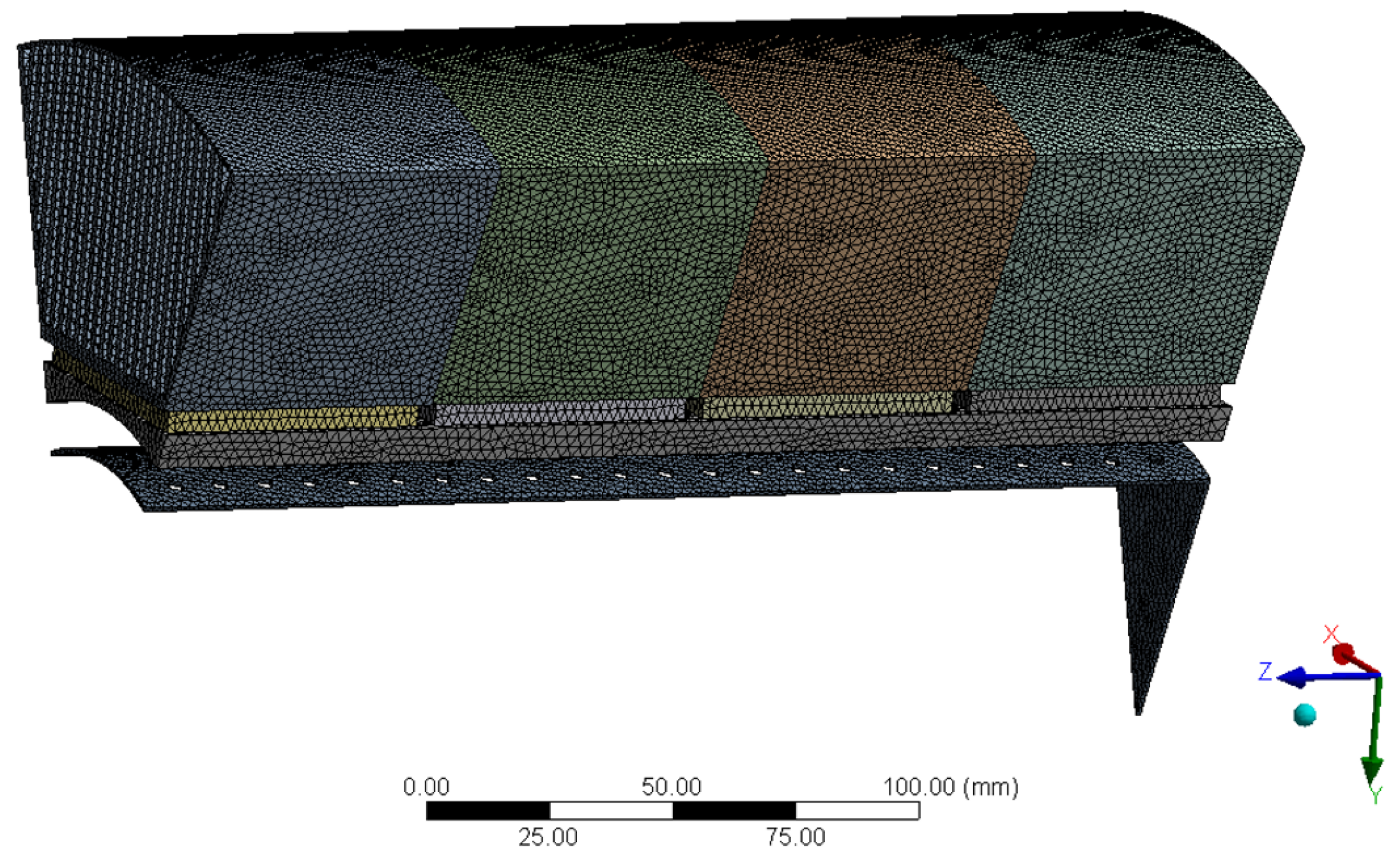
As shown in Figure 4, because the distributor in this model was cylindrical, to prevent simulation errors caused by the numerous grids in the simulation process, the simulation module was replaced with one-eighth of the model.

3.2. Grid Independence Test

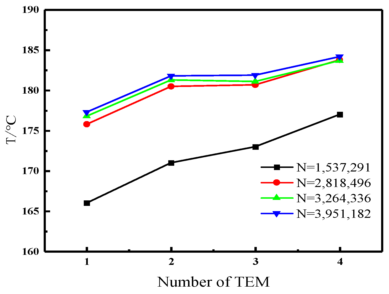
The grid independence check is a test used to determine whether or not calculated results are related to mesh density. It is a key step in finite element analysis. The optimization degree of mesh quality is positively correlated with the accuracy of the simulation results. The usual method is to increase the grid count by a percentage to a specific value, and then to increase the grid count so that the calculation results change little or experience no change, because a small number of grids will cause the calculation results to be inaccurate and increase the error; when the number of grids is relatively dense, the accuracy of the calculation results can be improved. However, when the number of grids overflows, it will not only have little effect on improving calculation accuracy, but will also cause the grids to occupy a lot of computer resources, resulting in a significant decline in computing efficiency. Therefore, the grid independence test can make up for the deficiency of the test data to some extent. In this study, Ansys-Mesh (2022 R1) software was used to divide the unstructured grid of the thermoelectric power generation device, and the grid near the fin gap, narrow angle, and distribution hole was encrypted. For the area with a solid material structure such as the collector, a relatively large grid was used. The overall grid of the device presents a hierarchical layout with different regional densities.
In this study, the average temperature of the hot end of modules 1–4 was used as a reference to test grid independence. The distributor diameter, D, is 140 mm; the jet hole diameter, D, is 2 mm; and the jet hole spacing, L, is 10 mm. Figure 5 shows the temperature distribution under different grid numbers. When the number of grids is 2.8 million, increasing the number of grids had little effect on the temperature change at the hot end of the thermoelectric module, which proves that the model meets the requirement of grid independence. In summary, the grid independence verification showed that the selected mesh type and mesh size meet the calculation requirements.

3.3. Governing Equation

In the process of numerical calculation, any fluid flow is governed by the three elementary governing laws of conservation of mass, momentum, and energy, and must satisfy the essential governing equations: the mass conservation, momentum conservation, and energy equations. In addition, the high-temperature fluid used in this study was an incompressible fluid with a steady-state flow.
The mass conservation, momentum conservation, and energy conservation equation is given as follows:
The mass conservation equation is shown below:
u = 0
The momentum conservation equation is shown below:
ρ f ( u u ) = p + μ f 2 u
The energy conservation is shown below:
ρ f c p u T = k f T
where ρ f , k f , μ f , c p , T , p , and u are the density, thermal conductivity, dynamic viscosity, heat capacity, temperature, static pressure, and velocity vector of the fluid, respectively. The temperature of the inlet high-temperature flue gas is 1000   ° C , and the thermal conductivity ( k f ) of the flue gas at this time is 4.84 × 10 2   W / m ° C , the heat capacity ( c p ) is 1.306   KJ / kg ° C , the density ( ρ f ) is 0.275   kg / m 3 , and the dynamic viscosity ( μ f ) is 167 × 10 6   m 2 / s .

4. Boundary Conditions

The TEM TEP1-12656-0.8 used in previous studies was adopted in this study for the simulation, and the relevant parameters of the TEM were set by referencing the literature [33]. Before setting the boundary conditions, the following assumptions need to be made for the simulation of the high-temperature temperature difference power generation device: the fluid is a Constant incompressible fluid, steady state flow; no slip between the contact surfaces; ignore the radiation heat transfer of the fluid-solid coupling wall; The effect of gravity is not considered; the contact thermal resistance between the walls is negligible. The hot flue gas inlet of the collector and the cooling air inlet of the radiator were set as velocity inlets. The initial velocity of the high-temperature flue gas was set to 2.0 m/s at a temperature of 1000 °C. The initial velocity of the cooling air was 4.2 m/s at a temperature of 20 °C. The outlet boundary was established as the stress exit with a relative pressure of 0 Pa. In the wall types, except for the fluid-structure coupling wall, all other walls were designed as walls of natural heat transfer, and the SIMPLE algorithm was adopted for calculation in the simulation.

5. Results and Discussion

5.1. Effect of Distributor Diameter on Heat Transfer Performance

Figure 6 shows that the flue gas flow direction and cooling air flow direction are the same, and the diameter of the jet hole is 4 mm. When changing the diameter of the distributor size and determining the effect of this on the four thermoelectric modules’ temperature distribution, as can be seen from the figure, the thermoelectric module’s hot and cold end temperatures and the temperature difference along the direction of the flue gas flow show an upward trend, and the larger the diameter of the distributor, the more pronounced upward trend. As shown in Figure 6a, at module 1, the hot end temperature at D = 140 mm is the lowest at this time, which is 189 °C, while at module 2 and module 3, the hot end temperature of the distributor at D = 140 mm shows a large increase; the hot end temperatures of the distributor at D = 130 mm and D = 140 mm at module 3 are similar, and the hot end temperature of the distributor at D = 140 mm reaches the highest at module 4, which is 224 °C at this time.
The reason for this phenomenon is that the high-temperature flue gas enters the distributor and flows downstream to the end first, then returns after making contact with the wall. It is resisted by the downstream flue gas, which causes the flue gas to be discharged from the jet hole. Other conditions do not change; when the diameter of the distributor changes, the flue gas flows out of the jet hole into the annular flow channel between the distributor and the heat transfer channel, so the flow rate in the annular channel gradually increases along the direction of flue gas flow, corresponding to the heat transfer coefficient also increasing. Therefore, when the diameter of the distributor is D = 140 mm, it is more favorable to the heat transfer performance of the temperature difference power generation device.

5.2. Effect of Distance between Jet Holes on Heat Transfer Performance

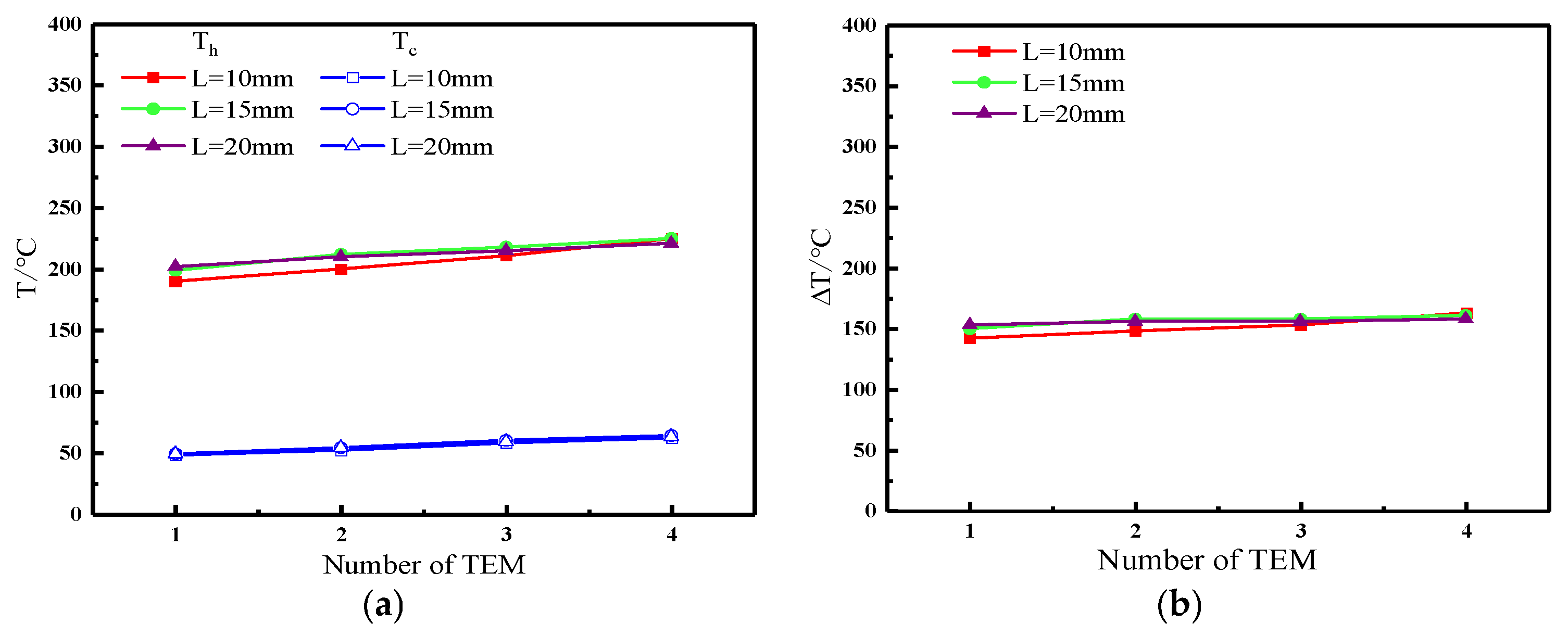
Figure 7 shows the temperature profile of the hot flue gas as it entered the distributor. High-temperature flue gas accumulated at the base of the distributor and was injected into the distributor through a small hole at the bottom. The temperature at the bottom of the distributor decreased, and heat transfer occurred in module 4, which had a higher temperature than the other modules. Figure 8 shows the flow field profile of the hot flue gas as it entered the distributor. The flue gases flowed into the base and then returned through the middle, creating a vortex at the bottom of the distributor. When the spacing of the jet holes increased, the swirl radius increased. The temperature variation trends of different TEMs are shown in Figure 9a. The effect of the variation in the distance between jet holes, L, on heat transfer performance was observed when the flue gas flow direction was the same as the cooling air flow direction, and the diameter of the jet holes was 2 mm. Overall, an increasing trend in the temperatures of modules 1–4 was observed. The hot end was significantly hotter than the cold end, and the resulting temperature difference was approximately 150 °C. At the cold end, the temperatures nearly coincided at different hole spacings, which had little influence on the cold end. At module 1, when the distance between jet holes was 20 mm, the temperature at the hot end reached 203 °C. The hot end temperature was second only to that at L = 20 mm, which was 200 °C. At L = 10 mm, the hot end temperature was the lowest, measuring 185 °C. In module 2, the hot end temperature remained the same at L = 15 and 20 mm, measuring 210 °C. At L = 10 mm, the lowest hot end temperature recorded was 192 °C. Interestingly, the hot end temperatures were consistent at L = 15 and 20 mm. In module 3, the temperatures for the three different hole spacings were similar. When the hole spacing was L = 20 mm, the temperature growth trend was slow, and increased by only 3 °C compared with that of module 2. The temperature was the highest when L = 15 mm, and the temperature growth trend was more significant when L = 10 mm, reaching 205 °C. At module 4, the temperature at the hot end reached the highest value of 225 °C when the spacing between jet holes was L = 15 mm and reached the lowest temperature of 210 °C when L = 10 mm.
The efficiency of thermal energy production is affected by the temperature gradient, which stretches from the hot end to the cold end. Therefore, to assess how heat transfer efficiency is affected by the spacing of the jet holes, the temperature heat transfer between the hot and cold ends was simulated. The results are presented in Figure 9b. The smallest temperature disparity between the hot and cold ends was observed when L = 10 mm. Conversely, the largest temperature difference occurred between modules 2 and 3. Remarkably, when L = 15 mm, the temperature difference remained the same as that at L = 10 mm. A noteworthy observation is that the minimum temperature disparity between the hot and cold ends was achieved when L = 10 mm, except in module 4, where the maximum temperature difference occurred at L = 10 mm, considering the jet hole distance.
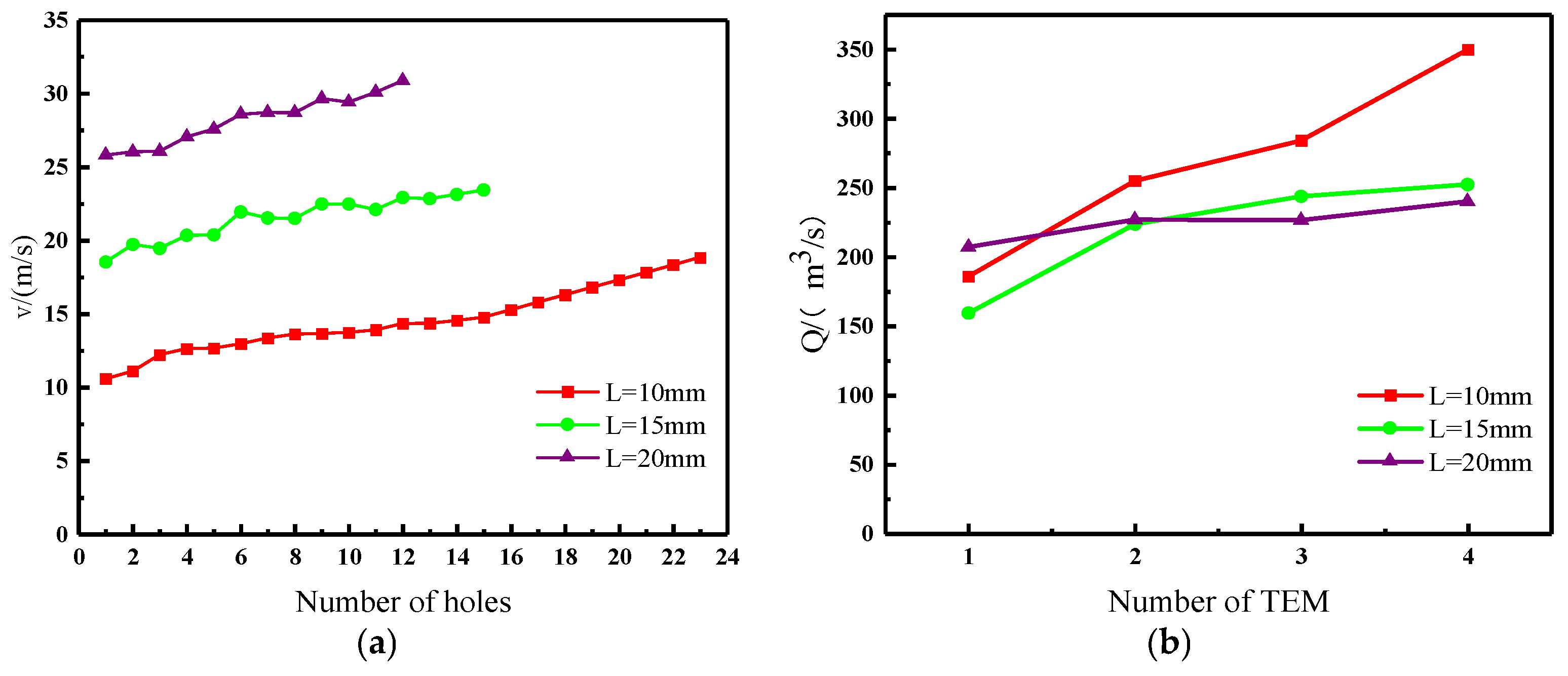
This phenomenon occurred because, after the high-temperature flue gas entered the distributor, it first flowed downstream to the end and then returned after touching the wall. It was subjected to the resistance of the downstream flue gas such that the flue gas was discharged from the jet hole. The size of the jet hole remained unchanged, whereas the number of jet holes decreased with an increase in spacing, and the flow velocity of the jet affected increased. As shown in Figure 10, in modules 1–3, the flow velocity of the distance between jet holes of L = 10 mm was far less than that between the other two types of jet holes, and the velocity was slightly different from that of the other two types of flows. However, in module 4, the flow velocity of the distance between jet holes of L = 10 mm was close to that of the other two types of flows, and the velocity increased significantly. Therefore, module 4 had the highest temperature.
According to the above discussion, it can be inferred that different distances between jet holes have a certain influence on the temperature variation at the hot end; however, the temperature variation’s range and influence on the heat transfer efficiency of the device are small. Therefore, in this study, a simulation analysis of the factors influencing the exhaust pressure drop was conducted. An excessive exhaust pressure drop leads to increased power consumption and affects heat transfer efficiency.
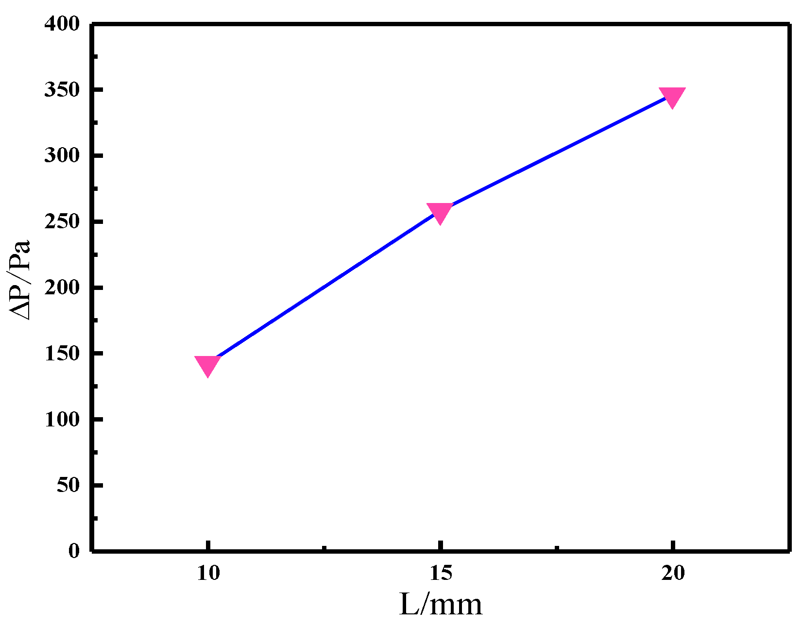
As depicted in Figure 11, the decrease in exhaust pressure through the jet orifice substantially increased as the spacing between the jet orifices increased. The smallest exhaust pressure drops of P = 145 Pa were observed when the distance between jet holes was L = 10 mm. When the hole spacing increased to L = 15 mm, this value was P = 258 Pa. Under a larger hole spacing of L = 20 mm, this value was P = 345 Pa, with a significant pressure difference of 200 Pa detected between L = 10 and 20 mm. This phenomenon is attributed to the decrease in quantity as the distance between jet holes expands, despite the constant inflow of flue gas into the distributor. Consequently, the exhaust pressure drop increased with an increase in the distance between jet holes.
According to the analysis of the abovementioned simulation results, it was observed that the alteration in the distance between jet holes had a minor impact on the temperature at the hot end. However, it significantly influenced the pressure drop in the exhaust associated with the jet holes. In conclusion, the best heat transfer performance was achieved when the spacing, L, between the jet holes was 10 mm.

5.3. Effect of the Diameter of the Jet Hole on Heat Transfer Performance

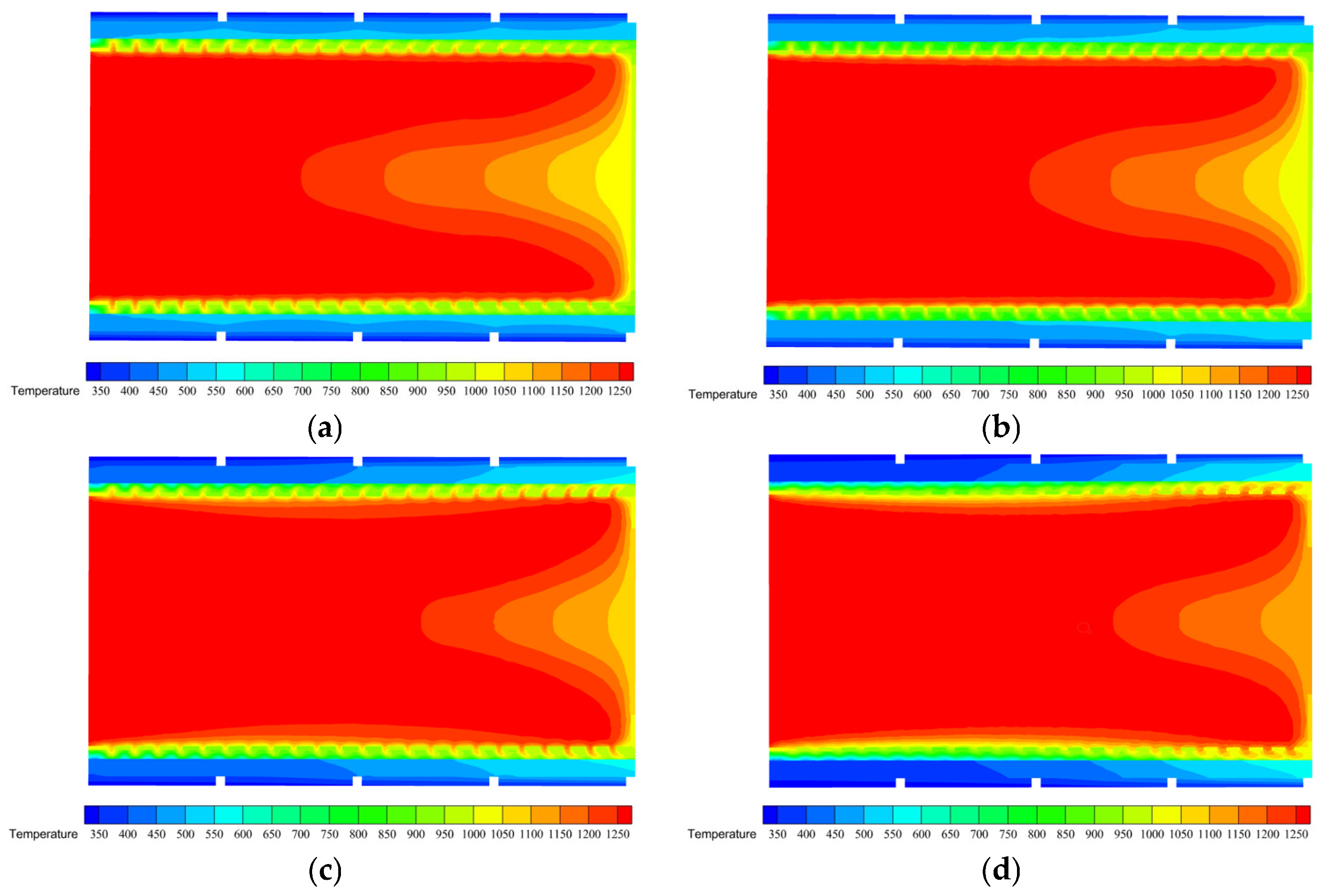
Heat transfer efficiency was optimized when the flow directions of the flue gas and cooling air were the same, and when the distance between the jet holes was set to L = 10 mm. Nonetheless, owing to variations in the temperature of modules 1–4, a disparity was created. This discrepancy stemmed from the fact that, upon entering the distributor, the flue gas initially proceeded downstream toward the end and subsequently retraced its path upon collision with the wall. At this time, the flue gas was resisted by the downstream flue gas and discharged from the jet hole. The longer the return path, the greater the resistance received by the flue gas. Therefore, the amount of flue gas in the flow direction of module 4 was greater than that in the flow direction of module 1. To enhance the impact of this factor on heat transfer efficiency, a jet hole with gradual contraction was devised in this study. The diameters of module 1 (jet hole numbers 1–6), module 2 (jet hole numbers 7–12), module 3 (jet hole numbers 13–18), and module 4 (jet hole numbers 19–23) were 2.9, 2.5, 2.2 mm, and 2.0 mm, respectively, and the distance between jet holes was 10 mm.
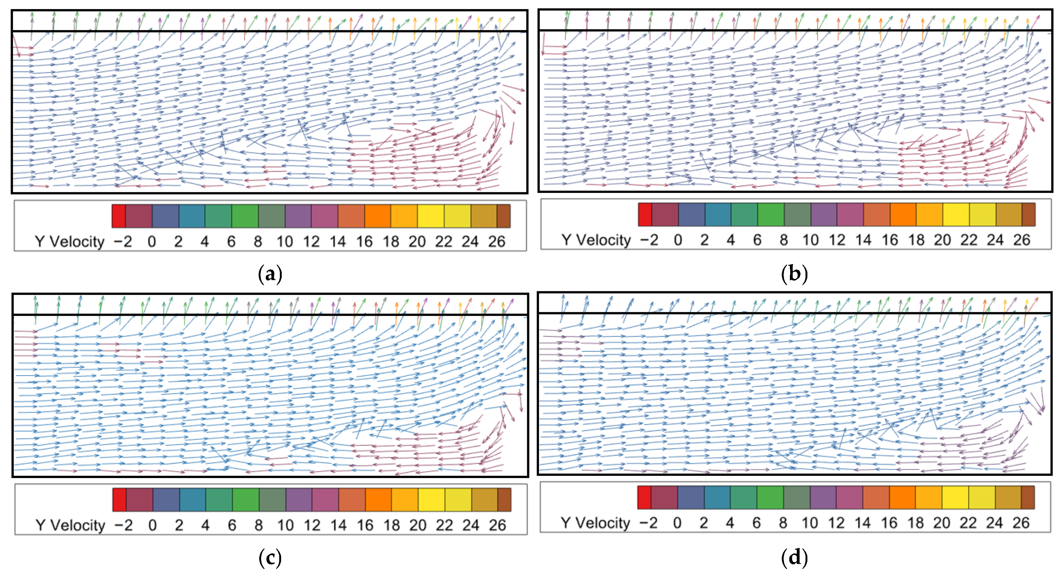
Figure 12 shows the temperature distributions under various orifice diameters. Upon entering the distributor, the high-temperature flue gas accumulated in the lower section. The temperature in the lower section of the distributor gradually increased as the orifice diameter increased. The flow field distributions at various orifice diameters are shown in Figure 13. The high-temperature flue gas moved toward the lower section of the distributor, experienced resistance, and then formed a swirling motion before returning. The simulation results for gradually increasing contraction diameters and jet hole diameters of 2, 3, and 4 mm were imported into software. The temperature changes in different modules are shown in Figure 14a. The investigation focused on examining the impact of different jet hole diameters on heat transfer performance while maintaining a consistent spacing of 10 mm. The analysis of module temperatures 1–4 revealed an increasing trend. Specifically, the temperature on the hot side (Th) consistently exceeded that on the cold side (Tc), albeit with a small gentle slope. The temperature on the cold side remained relatively constant across different hole spacings, indicating minimal influence. At the hot end, modules 1–3 showed higher temperatures for the gradual contraction-type jet hole than for the other diameters. Notably, in module 1, the highest temperature was observed at the hot end of the gradual contraction-type jet hole, with a subsequent gradual increase. This growth in temperature was gentle, with a difference of only 14 °C between the highest and lowest temperatures. At a jet hole diameter of 4 mm, module 1 recorded the lowest temperature of 97 °C, followed by a rapid increase in temperature. In module 4, the highest temperature was observed at the hot end of the jet hole diameter of 3 mm, and the lowest temperature was recorded for the jet hole with a diameter of 2 mm.
To directly observe the temperature disparity, the results are shown in Figure 14b. Although the temperature variations at the cold and hot ends of the gradual contraction-type jet hole exhibited minor fluctuations, they demonstrated a tendency toward overall stability. Moreover, the temperature difference in each module was greater than that at the hot end of the jet hole, which had a diameter of 2 mm. Notably, in module 1, the temperature difference between the cold and hot ends of the gradual contraction-type jet hole demonstrated a 125 °C difference from the temperature observed at the cold and hot ends of the jet hole with a diameter of 4 mm. However, as the flue gas flowed through, the temperature difference between the cold and hot ends of the 4 mm diameter jet hole reached its peak in module 4.
The reason for this phenomenon is that when the distance between the jet holes remained unchanged, the high-temperature flue gas first passed through the minimum aperture when it touched the wall for reflux. At this time, as illustrated in Figure 15a, the size of the pore diameter in the jet hole became relatively decreased, resulting in an increased velocity of the flue gas. Consequently, the convective heat transfer coefficient showed an amplified value, and the distance traveled by the flue gas affecting the jet through the jet hole was extended, thereby enhancing the interaction between the flue gas and the inner surface of the HEX. However, owing to the different diameters of the jet holes, the flow rate per unit time also varied. As shown in Figure 15b, in modules 2–3, the flow rate through the large aperture in unit time increased rapidly with an increase in the flue gas velocity; hence, it appeared in modules 1–3. The jet hole with a diameter of 4 mm exhibited significantly lower temperature values compared with those of other diameters. Consequently, the jet hole with a diameter of 4 mm attained the highest temperature level.
Factors affecting the heat transfer efficiency of a thermoelectric unit include not only the temperature difference but also the flow rate of the flue gas. To optimize the TEGs more comprehensively, the exhaust pressure drops of holes with different diameters were analyzed in this study. As shown in Figure 16, when the spacing of the jet holes was unchanged, the exhaust pressure drop of jet holes with a diameter of 2 mm was 142 Pa and that of the gradual contraction-type jet holes was 132 Pa. Although the drop in exhaust pressure may show a minimal disparity, a lower exhaust pressure drop is advantageous for enhancing the heat transfer efficiency of the TEG.

5.4. Effect of Cooling Air Flow Direction on Heat Transfer Performance

During the heat exchange process, the hot flue gas effectively transferred the heat to the cooling air within the distributor. The flow of cooling air was positive, starting from module 1 and ending at module 4. Throughout this process, there was a general increasing trend in temperature across modules 1–4. To further analyze the influence of the cooling airflow on the temperature of the module and its impact on the heat transfer performance, it is necessary to alter the airflow direction.
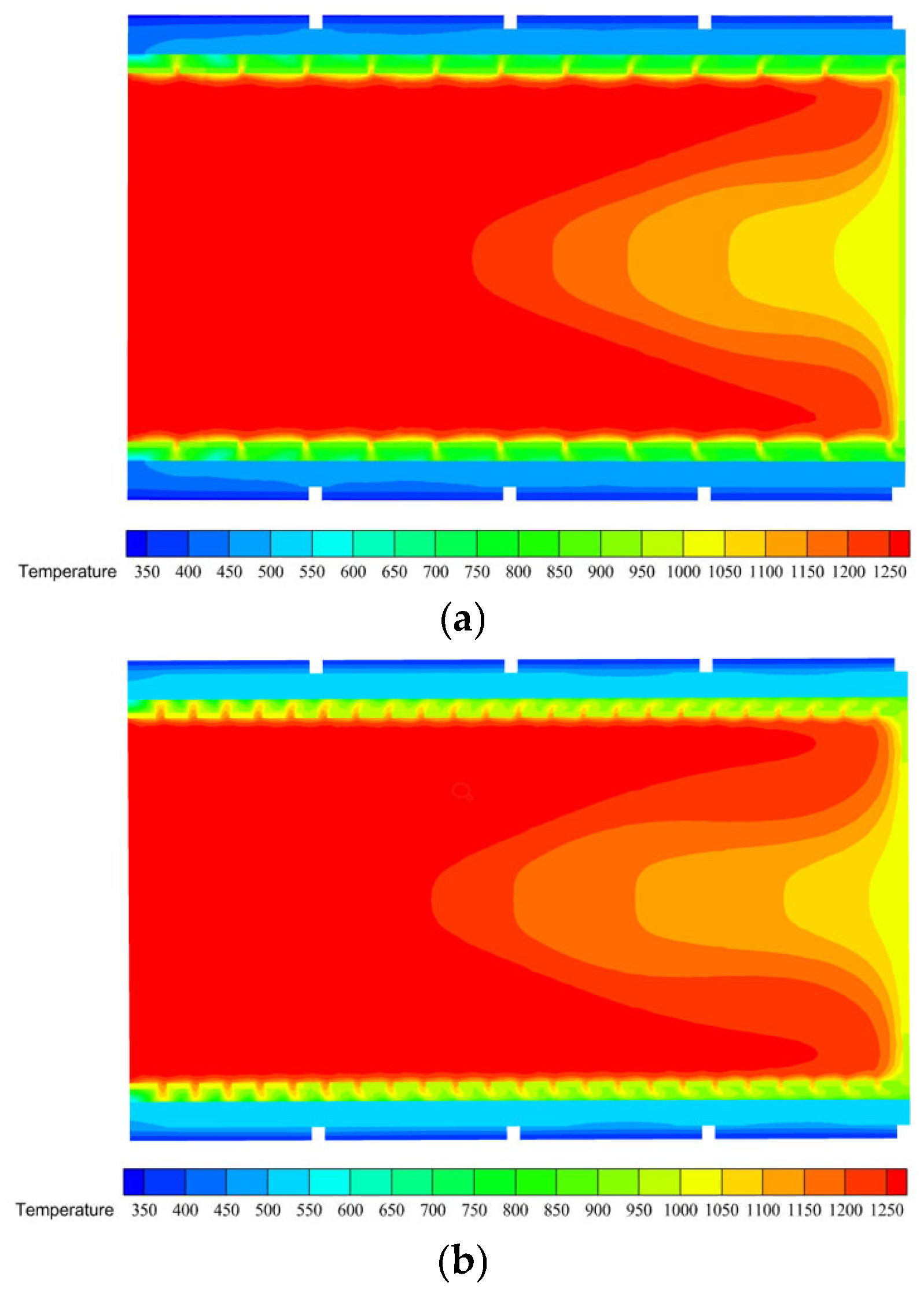
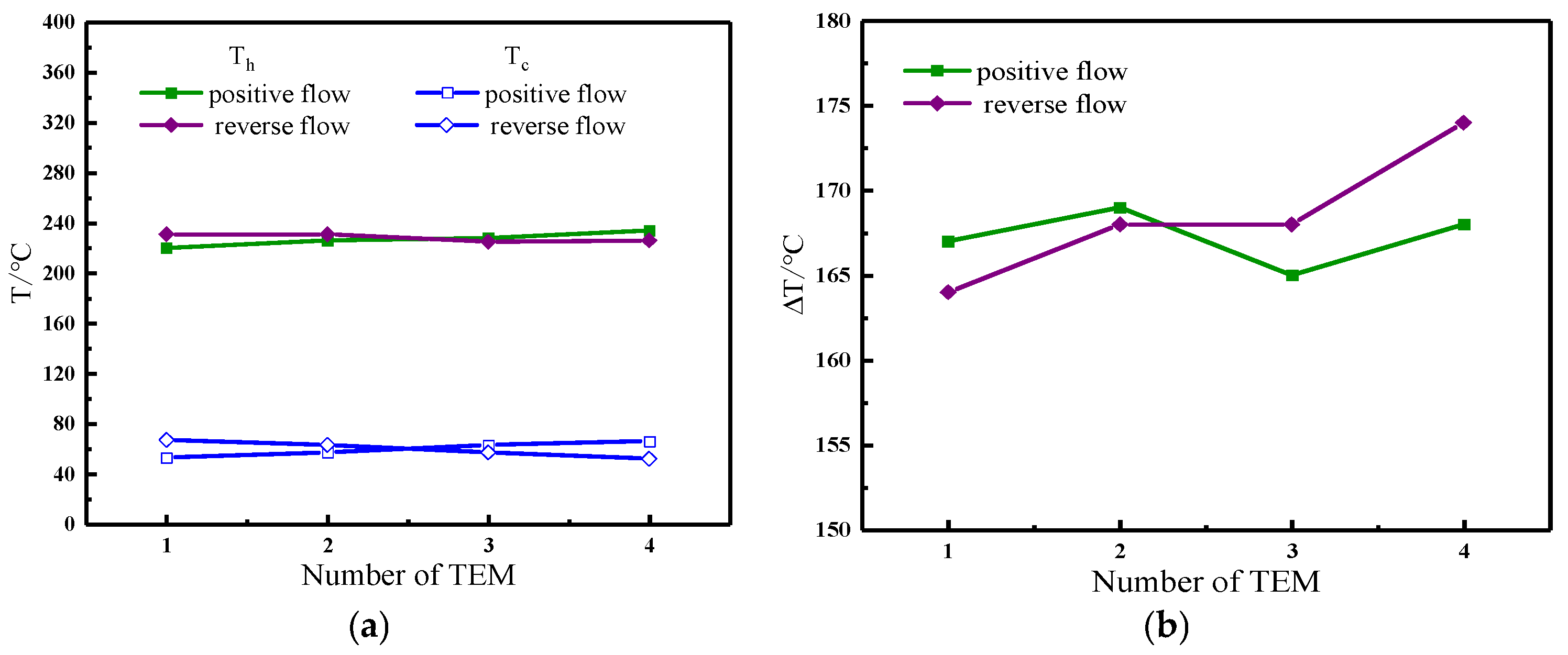
When the distance between the jet holes was adjusted to 10 mm, and the jet holes exhibited gradual contraction, the airflow direction of the cooling air changed. The temperature distribution following the introduction of the high-temperature flue gas into the distributor is shown in Figure 15. As the high-temperature flue gas flowed, it accumulated at the bottom of the distributor, causing it to collide with and affect the jet emanating from the bottom hole. Consequently, the temperature at the bottom of the distributor decreased. The results are shown in Figure 17a. Upon conducting an overall analysis, it was evident that the temperature change trend for modules 1–4 located at the hot end was relatively gentle, with no noticeable temperature fluctuations. The temperature of the modules increased when the air for cooling was directed toward a positive flow. Conversely, the temperature of the modules decreased when the cooling air was directed in the opposite direction. Specifically, when the cooling air flowed in the positive direction, module 4 attained the highest temperature of 234 °C. However, when the cooling air flowed in the opposite direction, module 1 reached the highest temperature of 231 °C.
Based on the information provided, it is challenging to accurately determine which flow direction of the cooling air is more favorable for convective heat transfer because of the similar temperatures of the four modules when the flow directions of the cooling air differed. Consequently, this study compared the temperature disparities between the cold and hot ends of the four modules in two distinct flow directions, as illustrated in Figure 18b. There was a noticeable similarity in the temperature discrepancy among the four modules when comparing the two different modes of cooling air, and it appeared to follow a gradual pattern. However, modules 1–2 demonstrated a greater temperature difference in the positive flow mode than in the reverse flow mode, whereas modules 3–4 exhibited a greater temperature difference in the reverse flow mode than in the positive flow mode. Remarkably, the direction of the flue gas entering the distributor remained unaltered, and the flow rate through the distributor hole remained constant. In addition, the exhaust pressure drop from the jet hole was unaffected by the two flow modes of refrigerated air. Consequently, the reverse flow of the cooling air provided greater benefits to the heat transfer performance of the device.
This phenomenon occurred because of the entry of high-temperature flue gas into the distributor, and the temperature in module 4 was the highest. Currently, the refrigerating air flowed backward and passed through module 4 first, increasing the temperature difference in module 4. The temperature differences in modules 1–3 were similar and were more conducive to enhancing the heat transfer efficiency of the device.

6. Conclusions

The utilization and recovery of energy highly depend on the heat transfer performance of TEG devices. This study simulated a cylindrical TEG device to investigate the impact of various structural distributors and jet holes on its heat transfer performance. Additionally, the degree of influence of different directions of the cooling air flow on the heat transfer performance of the TEG device was discussed. The key findings are as follows:
(1)
Efficient heat transfer can be achieved by having a distributor in the heat exchanger of a temperature difference power generation system. The temperature of the hot and cold ends of the thermoelectric module increases slightly along the flue gas flow direction, and increasing the diameter of the distributor can increase the temperature difference between the hot and cold ends of the thermoelectric module to a certain extent, but too large a distributor diameter will reduce the uniformity of the temperature distribution and temperature difference of the thermoelectric module. In this paper, the heat transfer performance of the temperature difference power generation device is better when the diameter of the distributor is 140 mm.
(2)
To study the impact of different distance between jet holes on the heat transfer efficiency of the device, various configurations were explored. The first setup involved a distributor diameter of 140 mm and a jet hole diameter of 2 mm. Tests were conducted by adjusting the distance between jet holes to 10, 15, and 20 mm. Upon analyzing the simulation results, no notable variations were observed in the temperature trend at the hot end of the three spacings. Moreover, the temperature disparity between the cooled and heated ends remained consistent across all the configurations. However, it is worth noting that when the distance between jet holes was set to 10 mm, the exhaust pressure drop was the lowest compared with that under the other two spacings. Consequently, it can be deduced that the device achieved the best heat transfer performance when the distance between the distance between jet holes was adjusted to 10 mm.
(3)
When the distributor had a diameter of 140 mm and the distance between jet holes was 10 mm, the cooling air flowed forward. In this study, the jet hole diameter was modified to create a gradual-contraction design. The jet hole diameters of modules 1, 2, 3, and 4 were 2.9 mm, 2.5 mm, 2.2 mm, and 2.0 mm, respectively. A comparison of the simulation results revealed that the gradual contraction of the jet hole diameter promoted a more uniform flow through the jet hole. Furthermore, this led to higher temperatures at both the cold and hot ends of the system and decreased the exhaust pressure drop. Consequently, it can be concluded that the heat transfer performance of the device is enhanced when the jet hole diameter undergoes gradual contraction.
(4)
When the distributor had a diameter of 140 mm and the distance between jet holes was 10 mm, the jet holes exhibited a gradual change in the diameter, and the airflow direction of the cooling air was altered. The air flowed in the same direction as that of the high-temperature flue gas, and was therefore in positive flow. Conversely, when the air flowed against the high-temperature flue gas, it was in reverse flow. A comparison of the simulation results showed that the temperature difference exhibited a similar trend for modules 1–3. However, module 4 exhibited a larger temperature difference in the reverse flow. In addition, the flow direction of the high-temperature flue gas and the exhaust pressure drop remained constant. Consequently, it can be inferred that the heat exchange performance of the device is superior when the cooling air and high-temperature flue gas flows are reversed.

Author Contributions

Conceptualization, H.G.; Methodology, R.W.; Software, X.L.; Validation, Y.M.; Formal analysis, C.Z. All authors have read and agreed to the published version of the manuscript.

Funding

This research was funded by [National Natural Science Foundation of China] grant number [52176132], [Innovation Capability Support Program of Shaanxi] grant number [2021TD-27], and [Natural Science Foundation of Shaanxi Province of China] grant number [2018JM5077].

Data Availability Statement

Data are contained within the article.

Conflicts of Interest

The authors declare no conflict of interest.

Nomenclature and Abbreviations

Nomenclature
Lspacing of jet holes, mm
djet hole diameter, mm
Ddistributor diameter, mm
uvelocity vector, m/s
T temperature, K
Pstatic pressure, Pa
Varea-averaged velocity, m/s
Qflow rate, m3/s
Thhot end temperature, K
Tccold end temperature, K
Abbreviations
TEGthermoelectric generator
TEMthermoelectric module
HEXheat exchanger

References

  1. Siddique, A.R.M.; Mahmud, S.; Heyst, B.V. A review of the state of the science on wearable thermoelectric power generators (TEGs) and their existing challenges. Renew. Sustain. Energy Rev. 2017, 73, 730–744. [Google Scholar] [CrossRef]
  2. Elsheikh, M.H.; Shnawah, D.A.; Sabri, M.F.M. A review on thermoelectric renewable energy: Principle parameters that affect their performance. Renew. Sustain. Energy Rev. 2014, 30, 337–355. [Google Scholar] [CrossRef]
  3. Suarez, F.; Parekh, D.P.; Ladd, C.; Vashaee, D.; Dickey, M.D. Flexible thermoelectric generator using bulk legs and liquid metal interconnects for wearable electronics. Appl. Energy 2017, 202, 736–745. [Google Scholar] [CrossRef]
  4. Jung, Y.S.; Jeong, D.H.; Kang, S.B.; Kim, F.; Jeong, M.H.; Lee, K.-S.; Son, J.S.; Baik, J.M.; Kim, J.-S.; Choi, K.J. Wearable solar thermoelectric generator driven by unprecedentedly high temperature difference. Nano Energy 2017, 40, 663–672. [Google Scholar] [CrossRef]
  5. Khanmohammadi, S.; Baseri, M.M.; Ahmadi, P.; Al-Rashed, A.A.A.; Afrand, M. Proposal of a novel integrated ocean thermal energy conversion system with flat plate solar collector and thermoelectric generator: Energy, exergy, environmental analyses. J. Clean. Prod. 2020, 256, 120600. [Google Scholar] [CrossRef]
  6. Qiang, J.W.; Yu, C.G.; Deng, Y.D.; Su, C.Q.; Wang, Y.P.; Yuan, X.H. Multi-objective optimization design for cooling unit of automotive exhaust-based thermoelectric generators. J. Electron. Mater. 2016, 45, 1679–1688. [Google Scholar] [CrossRef]
  7. Junior, O.H.A.; Maran, A.L.O.; Henao, N.C. A review of the development and applications of thermoelectric microgenerators for energy harvesting. Renew. Sustain. Energy Rev. 2018, 91, 376–393. [Google Scholar] [CrossRef]
  8. Bao, S.; Zhu, W.; Yu, Y.; Liang, L.; Deng, Y. Wearable Thermoelectric Generator with Cooling-Enhanced Electrode Design for High-Efficient Human Body Heat Harvesting. Appl. Energy 2016, 182, 518–524. [Google Scholar] [CrossRef]
  9. Nithyanandam, K.; Mahajan, R.L. Evaluation of metal foam based thermoelectric generators for automobile waste heat recovery. Int. J. Heat Mass Transf. 2018, 122, 877–883. [Google Scholar] [CrossRef]
  10. Kim, S.J.; We, J.H. wearable thermoelectric generator fabricated on a glass fabric. Energy Environ. Sci. 2014, 7, 1959–1965. [Google Scholar] [CrossRef]
  11. Lu, Z.; Zhang, H.; Mao, C.; Li, C.M. Silk fabric-based wearable thermoelectric generator for energy harvesting from the human body. Appl. Energy 2016, 164, 57–63. [Google Scholar] [CrossRef]
  12. Wang, L.; Liu, Y.; Zhang, Z.; Wang, B.; Qiu, J.; Hui, D.; Wang, S. Polymer composites-based thermoelectric materials and devices. Compos. Part B—Eng. 2017, 122, 145–155. [Google Scholar] [CrossRef]
  13. Bai, S.; Lu, H.; Wu, T.; Yin, X.; Shi, X.; Chen, L. Numerical and experimental analysis for exhaust heat exchangers in automobile thermoelectric generators. Case Stud. Therm. Eng. 2014, 4, 99–112. [Google Scholar] [CrossRef]
  14. Quan, R.; Tang, X.; Quan, S.; Huang, L. A novel optimization method for the electric topology of thermoelectric modules used in an automobile exhaust thermoelectric generator. J. Electron. Mater. 2013, 42, 1469–1475. [Google Scholar] [CrossRef]
  15. Liu, C.; Deng, Y.D.; Wang, X.Y.; Liu, X.; Wang, Y.P. Multi-objective optimization of heat exchanger in an automotive exhaust thermoelectric generator. Appl. Therm. Eng. 2016, 108, 916–926. [Google Scholar] [CrossRef]
  16. Fernández-Yañez, P.; Armas, O.; Capetillo, A.; Martínez-Martínez, S. Thermal analysis of a thermoelectric generator for light-duty diesel engines. Appl. Energy 2018, 226, 690–702. [Google Scholar] [CrossRef]
  17. Kim, T.Y.; Lee, S.; Lee, J. Fabrication of thermoelectric modules and heat transfer analysis on internal plate fin structures of a thermoelectric generator. Energy Convers. Manag. 2016, 124, 470–479. [Google Scholar] [CrossRef]
  18. Ma, T.; Lu, X.; Pandit, J.; Ekkad, S.V.; Huxtable, S.T.; Deshpande, S.; Wang, Q.W. Numerical study on thermoelectric–hydraulic performance of a thermoelectric power generator with a plate-fin heat exchanger with longitudinal vortex generators. Appl. Energy 2017, 185, 1343–1354. [Google Scholar] [CrossRef]
  19. Liu, X.; Deng, Y.D.; Zhang, K.; Xu, M.; Xu, Y.; Su, C.Q. Experiments and simulations on heat exchangers in thermoelectric generator for automotive application. Appl. Therm. Eng. 2014, 71, 364–370. [Google Scholar] [CrossRef]
  20. Su, C.Q.; Wang, W.S. Simulation and experimental study on thermal optimization of the heat exchanger for automotive exhaust-based thermoelectric generators. Case Stud. Therm. Eng. 2014, 4, 85–91. [Google Scholar] [CrossRef]
  21. Hassan, M.A.; Samanta, R. Heat exchanger assisted exhaust heat recovery with thermoelectric generator in heavy vehicles. Energy Technol.-Ger. 2021, 9, 2100037. [Google Scholar] [CrossRef]
  22. Wang, Y.; Li, S.; Xie, X.; Deng, Y.; Liu, X.; Su, C. Performance evaluation of an automotive thermoelectric generator with inserted fins or dimpled-surface hot heat exchanger. Appl. Energy 2018, 218, 391–401. [Google Scholar] [CrossRef]
  23. Marvão, A.; Coelho, P.J.; Rodrigues, H.C. Optimization of a thermoelectric generator for heavy-duty vehicles. Energy Convers. Manag. 2019, 179, 178–191. [Google Scholar] [CrossRef]
  24. Adavbiele, A.S. Generation of electricity from gasoline engine waste heat. J. Energy Technol. Policy 2013, 3, 3–16. Available online: https://api.semanticscholar.org/CorpusID:214737305 (accessed on 10 January 2024).
  25. Huang, K.; Yan, Y.; Li, B. Comprehensive performance analysis of concentric cylindrical thermoelectric generator for light-duty vehicles. In Proceedings of the International Heat Transfer Conference 16, Beijing, China, 10–15 August 2018. [Google Scholar] [CrossRef]
  26. Weng, C.C.; Huang, M.J. A simulation study of automotive waste heat recovery using a thermoelectric power generator. Int. J. Therm. Sci. 2013, 71, 302–309. [Google Scholar] [CrossRef]
  27. Bai, W.; Yuan, X.; Liu, X. Numerical investigation on the performances of automotive thermoelectric generator employing metal foam. Appl. Therm. Eng. 2017, 124, 178–184. [Google Scholar] [CrossRef]
  28. Borcuch, M.; Musiał, M.; Gumuła, S.; Sztekler, K.; Wojciechowski, K. Analysis of the fins geometry of a hot-side heat exchanger on the performance parameters of a thermoelectric generation system. Appl. Therm. Eng. 2017, 127, 1355–1363. [Google Scholar] [CrossRef]
  29. Cao, Q.; Luan, W.; Wang, T. Performance enhancement of heat pipes assisted thermoelectric generator for automobile exhaust heat recovery. Appl. Therm. Eng. 2018, 130, 1472–1479. [Google Scholar] [CrossRef]
  30. Kim, T.Y.; Kwak, J.; Kim, B. Energy harvesting performance of hexagonal shaped thermoelectric generator for passenger vehicle applications: An experimental approach. Energy Convers. Manag. 2018, 160, 14–21. [Google Scholar] [CrossRef]
  31. Yang, H.; Shu, G.; Tian, H.; Ma, X.; Chen, T.; Liu, P. Optimization of thermoelectric generator (TEG) integrated with three-way catalytic converter (TWC) for harvesting engine’s exhaust waste heat. Appl. Therm. Eng. 2018, 144, 628–638. [Google Scholar] [CrossRef]
  32. Shu, G.; Ma, X.; Tian, H.; Yang, H.; Chen, T.; Li, X. Configuration optimization of the segmented modules in an exhaust-based thermoelectric generator for engine waste heat recovery. Energy 2018, 160, 612–624. [Google Scholar] [CrossRef]
  33. Gao, H.B.; Zong, S.C.; Zhang, C.W.; Li, H.J.; Huang, G.H. Experimental investigation of the performance of a thermoelectric generator at various operating conditions. IOP Conf. Ser. Earth Environ. Sci. 2021, 702, 012001. [Google Scholar] [CrossRef]
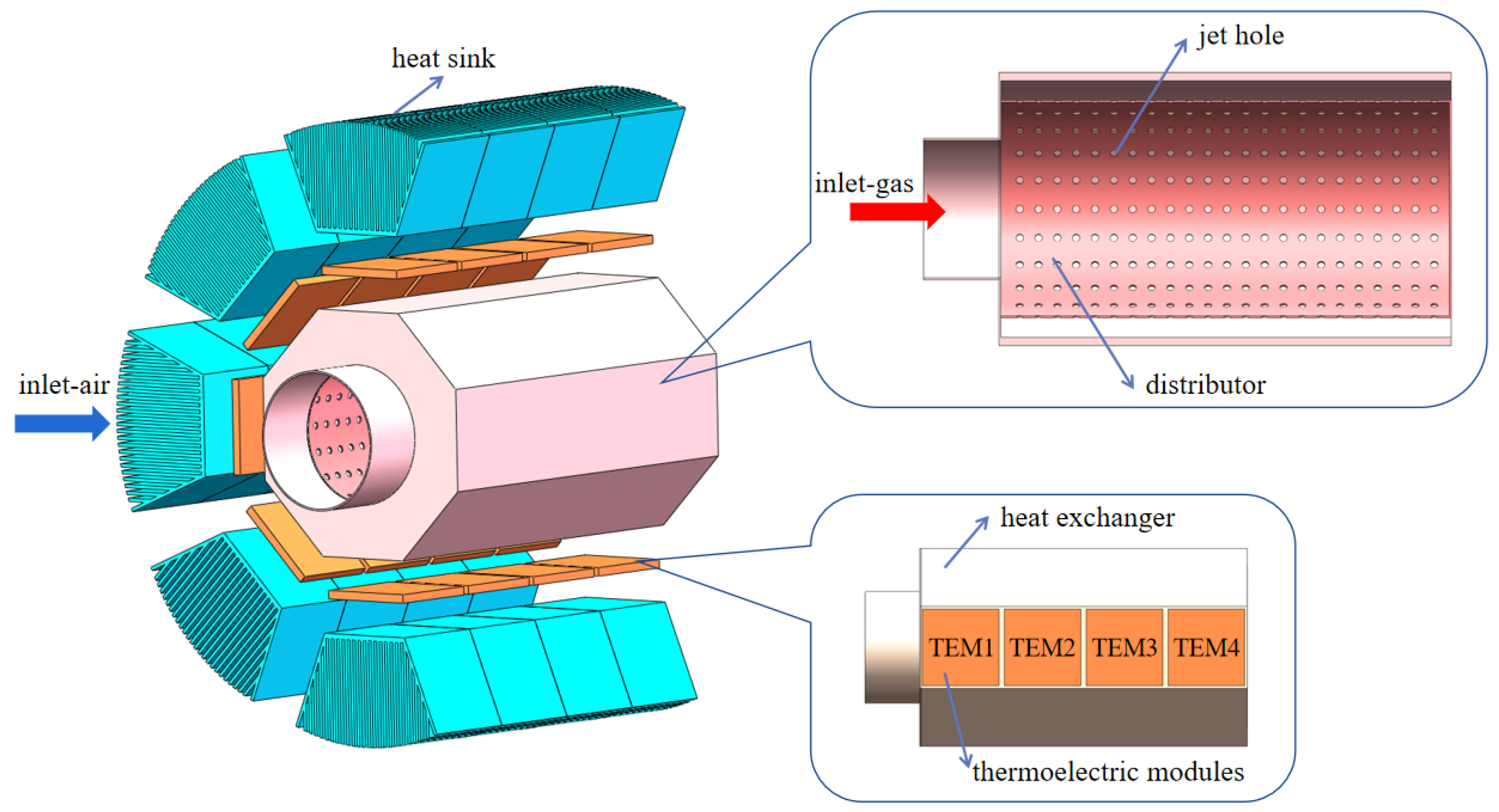
Figure 1. Schematic of the TEG system.
Energies 17 01121 g001
Figure 2. Schematic of the distributor’s structure.
Energies 17 01121 g002
Figure 3. Direction of cooling air flow: (a) positive flow; (b) reverse flow. Blue areas are TEMs; pink area is distributor.
Energies 17 01121 g003
Figure 4. Mesh of the TEG system.
Energies 17 01121 g004
Figure 5. Temperature of the hot end at different mesh counts.
Energies 17 01121 g005
Figure 6. Temperature of TEMS at different distributor diameters (d = 2 mm). (a) Th and Tc of TEMs; (b) ΔT of TEMs.
Energies 17 01121 g006
Figure 7. Temperature distribution at different distances between jet holes: (a) L = 10 mm; (b) L = 15 mm; (c) L = 20 mm.
Energies 17 01121 g007
Figure 8. Flow field distribution under different distances between jet holes: (a) L = 10 mm; (b) L = 15 mm; (c) L = 20 mm.
Energies 17 01121 g008
Figure 9. Temperature of TEMS at different distances between jet holes. (a) Th and Tc of TEMs; (b) ΔT of TEMs.
Energies 17 01121 g009
Figure 10. Influence of distance between jet holes on the velocity and flow rate of flue gas. (a) Velocity of flue gas; (b) flow rate of flue gas.
Energies 17 01121 g010
Figure 11. Influence of exhaust pressure drop under different distances between jet holes.
Energies 17 01121 g011
Figure 12. Temperature distribution under different jet hole diameters: (a) d = 2.9–2.0 mm; (b) d = 2 mm; (c) d = 3 mm; (d) d = 4 mm.
Energies 17 01121 g012
Figure 13. Flow field distribution under different jet hole diameters: (a) d = 2.9–2.0 mm; (b) d = 2 mm; (c) d = 3 mm; (d) d = 4 mm.
Energies 17 01121 g013
Figure 14. Temperature of TEMS at different jet hole diameters. (a) Th and Tc of TEMs; (b) ΔT of TEMs.
Energies 17 01121 g014
Figure 15. Effect of jet hole diameter on the velocity and flow rate of flue gas. (a) Velocity of flue gas; (b) flow rate of flue gas.
Energies 17 01121 g015
Figure 16. Influence of exhaust pressure drop under different jet hole diameters.
Energies 17 01121 g016
Figure 17. Temperature distribution of the cooling air in different flow directions. (a) Flow of the cooling air and flue gas in the same direction; (b) flow of the cooling air and flue gas in opposite directions.
Energies 17 01121 g017
Figure 18. Temperature changes under different directions of cooling air flow. (a) Th and Tc of TEMs; (b) ΔT of TEMs.
Energies 17 01121 g018
Disclaimer/Publisher’s Note: The statements, opinions and data contained in all publications are solely those of the individual author(s) and contributor(s) and not of MDPI and/or the editor(s). MDPI and/or the editor(s) disclaim responsibility for any injury to people or property resulting from any ideas, methods, instructions or products referred to in the content.