Article

Linear Matrix Inequality-Based Robust Model Predictive Speed Control for a Permanent Magnetic Synchronous Motor with a Disturbance Observer

Electric Power System Research Laboratory, Korea Institute of Energy Research (KIER), 200 Haemajihaean-ro, Gujwa-eup, Jeju-si 63357, Republic of Korea
*
Authors to whom correspondence should be addressed.
Energies 2024, 17(4), 869; https://doi.org/10.3390/en17040869
Submission received: 14 January 2024 / Revised: 1 February 2024 / Accepted: 8 February 2024 / Published: 13 February 2024
(This article belongs to the Section F: Electrical Engineering)

Abstract

:
In this paper, a linear matrix inequality (LMI)-based robust model predictive speed control (RMPSC) with a disturbance observer (DOB) is proposed to guarantee stability and control performance against the parameter uncertainty and disturbance of a permanent magnetic synchronous motor (PMSM). All external torques applied to the PMSM are defined as disturbance, estimated by the DOB, and used to construct the RMPSC method. The proposed DOB and RMPSC are determined by a multiple LMI-based optimization approach. Furthermore, parameter uncertainty within a certain range, due to manufacturing errors or aging deterioration, is considered and a systematic tuning method is proposed to obtain the optimal gains. Finally, an offline optimization method is developed that ensures a low computational load to enable real-time processing. Simulation results demonstrate the effectiveness and validity of the proposed control method.

1. Introduction

A permanent magnet synchronous motor (PMSM) is a type of electric motor whose utilization is increasing due to its various advantages [1,2] such as high efficiency, compact design, precise control, high torque-to-inertia ratio, and high power density. Therefore, PMSMs are used in a variety of fields [3,4,5,6] including CNC machines and robotics, which traditionally require precise control, as well as factory automation equipment, new and renewable energy production, space- and defense-related fields, and, recently, even for electric power steering (EPS) in the automobile industry. However, a PMSM is a time-varying system with nonlinearity that is mechanically coupled with other systems and operates with complex dynamics, causing many difficulties [7,8,9] in control system design.
To efficiently control such complex PMSM systems, control methods such as modified PI control [10,11,12,13,14], sliding mode control (SMC) [15,16,17,18], model predictive control (MPC) [19,20,21], and deep learning (DL)-based control [22,23,24] have been proposed. In [11,12,13,14], modified PI control-based methods were implemented. A vector-controlled PMSM drive using a hybrid fuzzy PI speed controller [11] that combines the advantages of a PI controller and a fuzzy controller was proposed. It is characterized by being a combination of two outputs to which a weight for a predetermined speed error or a weight for the actual speed error is assigned. In [12], a novel adaptive fuzzy proportional integral (AFPI) control method was introduce to address the system’s uncertain saturation, uncertain disturbances, and system delay. An online optimization adaptive fuzzy proportional integral (AFPI) control method was applied using the designed adaptive fuzzy tuner. On the other hand, Ref. [13] proposed a mixed PI controller consisting of angle compensation, complex coefficient, and proportional integrator controllers that provide decoupling performance for the delay time of digital control. In addition, a neural network-based PID controller is presented in [14]. Four control modules were combined to enable optimal gain adjustment of the online PID controller while considering nonlinearity. However, the PI control method generally has the limitation that it can only satisfy control performance within a certain range.
Meanwhile, several studies have been carried out to apply sliding mode control (SMC) [15,16,17,18], a method capable of effectively regulating nonlinear systems, in PMSMs. Simple model information is required to construct the SMC method, but it is used in many fields because it shows excellent control performance against disturbances. An extended state observer (ESO)-based anti-disturbance sliding-mode speed controller [15] was proposed. This method alleviates the chattering of the SMC and improves the response characteristics of the speed control, allowing the sliding mode surface to be reached quickly. A hybrid SMC combining sliding-mode- and deadbeat-based predictive current control was proposed in [16], and the results show robustness to variation in load and machine parameters by an integrated high-order sliding-mode observer. In [17], a singular-perturbation-based second-order sliding-mode controller that separates the slow-speed section and high-speed section was proposed. Depending on the speed of the PMSM, it was determined whether or not to apply a differentiator, and this resulted in a chattering reduction effect. There is also research on SMCs applying fuzzy control [18], considering disturbance inputs that represent PMSM system nonlinearity or unmodeled uncertainty.
As high-performance computing devices become more popular and cheaper, research combining model predictive control (MPC) with a PMSM [19,20,21] is also being actively conducted. In general, MPC can be divided into a finite control set (FCS) MPC and a continuous control set (CCS) MPC according to the control input space. FCS-MPC performs optimization based on a limited number of switching states and is widely used because it has a lower computational load and is easier to implement compared to CCS-MPC. A direct-torque control method [19], consisting of eight voltage space vectors of a two-level inverter has been presented, and torque ripple was reduced by using Lyapunov’s theory to determine the weights of the cost function. In [20], a generalized multiple-vector-based MPC for PMSM drives, which is integrated into one frame, was studied to reduce the amount of computation compared to existing MPCs. To reduce the amount of computation as in [20], a combination of deadbeat and MPC [21] was proposed to optimize the switching-vector selection procedure.
Recently, research on applying deep learning to PMSMs [22,23,24] has been conducted. To improve the performance of PMSMs in the electric aircraft field, a novel active disturbance rejection control based on deep reinforcement learning [22] was proposed. It trains a neural network using the twin-delayed deep deterministic (TDDD) policy gradient algorithm and performs optimization of the DRL model. Ref. [23] proposed a multi-scenario parameter optimization method that applied deep reinforcement learning to the optimization process of finding the parameters of the active disturbance rejection controller. In [24], a deep neural network (DNN)-based long-horizon MPC was proposed to achieve offset-free torque tracking. It highlights the practical advantages of utilizing MPC approximation in real-time through a DNN, specifically emphasizing the elimination of the need for solver development in real-time implementation.
This paper proposes a linear matrix inequality (LMI)-based robust model predictive speed control (RMPSC) with a disturbance observer (DOB) to regulate the speed of a PMSM that is robust in the face of unknown disturbances and parameter variations. All external torques connected with the PMSM are defined as disturbances and estimated by the DOB. In [7], a disturbance observer was designed based on the assumption that disturbances change slowly, and in [25] one was designed under the assumption that disturbances decrease. Thus, the estimated performance is limited for rapid changes in disturbances, and no specific method was provided to obtain disturbance observer gain. However, in order to ensure the estimated performance of a disturbance, the proposed DOB derives multiple LMIs based on the Lyapunov function and formalizes them as an optimization problem to obtain optimal disturbance gain. And the proposed RMPSC method with a DOB regulates the speed of the PMSM considering the uncertainty of the parameters. In addition, we propose a gain-tuning procedure to find the optimal gains of observer and controller. This proposed method is expected to be suitable for stable operation in environments where the PMSM’s parameters change due to long-term operation or torque changes rapidly [26,27].
The contribution of this study is to design a DOB to be used for prediction and control, and to demonstrate that the RMPSC method can stably control the speed of a PMSM with parameter uncertainty within a certain range due to manufacturing errors or deterioration caused by aging. And an optimization-based systematic-tuning method is proposed to find the optimal observer and controller gains. Additionally, we propose an offline optimization method that ensures a low computational load to enable real-time processing despite CCS-MPC.
The remainder of this paper is organized as follows. The system description of the PMSM is provided in Section 2. In Section 3, the disturbance observer and state observer are presented as the optimization methods. Section 4 explains the proposed RMPSC method, including parameter uncertainty and disturbance. The tuning procedure and simulation results are presented in Section 5. Finally, the conclusion is summarized in Section 6.

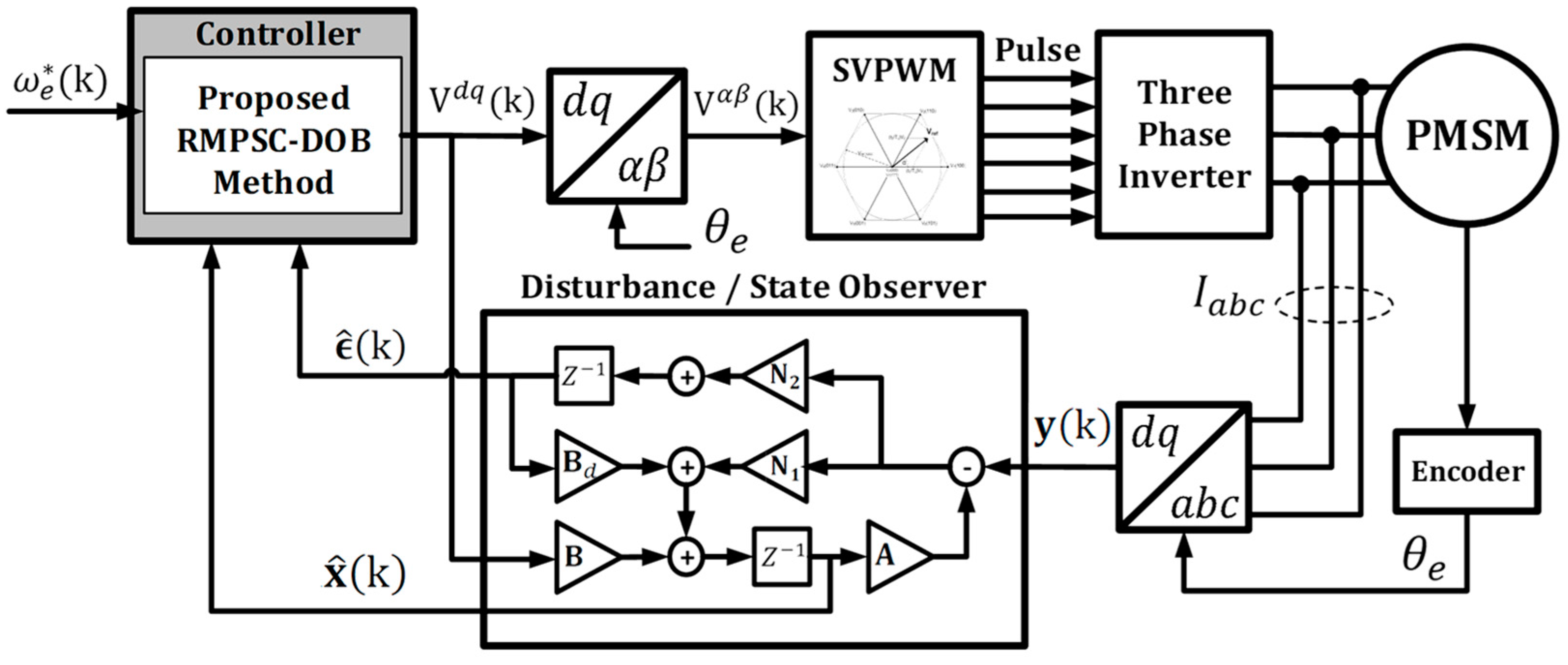
2. System Description

In many papers, the mathematical model of a PMSM is converted from a three-phase fixed-coordinate system to a two-axis rotation coordinate system for convenience of analysis and control [15]. The generalized nonlinear system dynamics of a PMSM can be represented in the synchronous reference frame (SRF) as follows:
V d = R s I d + d d t Φ d P ω m Φ q
V q = R s I q + d d t Φ q + P ω m Φ d
where V d , V q , I d , I q , R s , Φ d , Φ q , and ω m are the stator voltage, stator current, stator resistance, stator flux linkage, and rotor speed, respectively.
The PMSM stator flux linkage is expressed as:
Φ d = L d I d + λ r
Φ q = L q I q
where L d and I q are the stator inductance and λ r is the flux linkage of a permanent magnet, respectively.
The electromagnetic torque equation of the PMSM can be expressed as:
τ e = 3 2 P [ λ r I q + ( L d L q ) I d I q ]
where P is pole pairs of a PMSM.
Since a surface mounted type of PMSM (SPMSM) is used in this study, the value of L d and L q are the same. Therefore, the dynamics of electromagnetic torque are rewritten as:
τ e = 3 2 P λ r I q
The mechanical motion of the PMSM is expressed as:
τ m = τ e J d d t ω m F d d t θ m + δ
ω m = d d t θ m
where θ m , F and τ m are the rotor position, viscosity coefficient, and mechanical torque, and δ is the unknown external torque, respectively. Since the mechanical torque and unknown external torque cannot be measured in the system, these values are defined as disturbance d .
Substituting (6) in (7) yields
d d t ω m = K J I q + F J ω m + 1 J ϵ
where K 3 2 P λ r and disturbance ϵ τ m + δ .
The above Equations (1), (2) and (9) can be represented as follows:
d d t I d = R s L d I d + L q L d ω e I q + 1 L d V d
d d t I q = R s L q I q 1 L d λ r ω e ω e I d + 1 L q V q
d d t ω e = K P J I q F J ω e + P J ϵ
where ω e = P ω m .
To eliminate the interaction between ω e , I d , and I q , the reference current I d is usually assumed to be zero [28]. Therefore, the only control input that regulates the speed of the PMSM is stator voltage V q . Equations (11) and (12) can be presented as a linear state–space model as follows:
x ˙ t = A x t + B u t + B d d t y ( t ) = C x t
A = R s L q 1 L d λ r K P J F J , B = 1 L q 0 , B d = 0 P J , C = [ 1 0 ]
where x t = I q   ω e T , u t = [ V q ] , ϵ t = [ ϵ ] , and y t = I q are the state vector, control input, and measurement output, respectively.
Utilizing the Euler approximation [29], the linear state–space model in the continuous time of (13) can be converted to the following linear state–space model in discrete time using step time T s :
x k + 1 = A x k + B u k + B d ϵ k y k = C x k
where
A e A T s , B 0 T s e A τ d τ B , B d 0 T s e A τ d τ B d , C C

3. Disturbance and State Observer Design

As the mechanical rotating body connected to the PMSM comes into contact with an external system, the speed of the PMSM may change due to external mechanical torque. Therefore, if the external mechanical torque applied to the PMSM is predictable, the speed regulation performance of the PMSM can be improved. Meanwhile, the mechanical encoder of the PMSM has many limitations in installation and use due to wear and tear, lifespan, sensor sensitivity, and cost issues depending on the usage environment. Therefore, estimation of the PMSM’s speed, which is the role of the encoder, is needed.
In this section, we propose the disturbance observer and the state observer design method to estimate the disturbance ϵ and the state x , which are denoted by ϵ ^ and x ^ , respectively.
Let us assume that the disturbance ϵ ( k ) is a constant:
ϵ k + 1 = ϵ ( k )
It can be observed as
ϵ ^ k + 1 = ϵ ^ k + N 2 y k y ^ k .
where N 2 is disturbance observer gain.
And the full state observer of x is proposed as follows using state observer gain N 1 and the observed disturbance ϵ ^ .
x ^ k + 1 = A x ^ k + B u k + N 1 ( y k C x ^ k ) + B d ϵ ^ k
Subtracting the state observer (17) from state (14) and the disturbance observer (16) from disturbance (15) gives the following augmented equation:
z k + 1 = [ A e N C e ] z k
z k x ~ k ϵ ~ k A e A B d 0 1 × 2 1 , N N 1 N 2 , C e C   0 1 × 1 .
where x ~ k x k x ^ k and ϵ ~ k ϵ k ϵ ^ k .
Suppose the Lyapunov function, where P is a positive definite matrix, is defined as follows:
V k = z k T P z k
In Equation (19) above, the disturbance and state observer gain N is determined so that V k decreases [30] and it can be expressed as follows:
V k + 1 = z k T ( A e L C e T P [ A e N C e ] P ) z k < 0
where V k + 1 V k + 1 V k . Equation (20) is satisfied under the condition that z k is non-zero, and the following equation is fulfilled:
[ A e N C e ] T P [ A e N C e ] P < 0
If there exists a P o satisfying P > P o > 0 , and Equation (22), it is clear that Equation (21) holds.
P o [ P A e P N C e ] T P 1 [ P A e P N C e ] > 0
In (20), in order to reduce the Lyapunov function V k as quickly as possible at each step, the value of A e N C e T P [ A e N C e ] must become smaller. Therefore, to control the decay rate of the Lyapunov function, the value α is suggested as follows:
P o < α P
where 0 < α < 1 .
In Equation (23), it is evident that a decrease in the value of alpha α leads to a faster reduction in the Lyapunov function V k . And by applying Schur supplementary lemma [28], it can be converted as an LMI as follows.
P o [ P A e Y C e ] T [ P A e Y C e ] P > 0
where Y P N .
Assuming that the parameters of a PMSM have uncertainty relative to their nominal values due to manufacturing errors or aging degradation, the parameters containing uncertainty can be expressed as values within the following range:
R s o / μ R s o R s o μ L q o / μ L q o L q o μ J o / μ J o J o μ λ r o / μ λ r o λ r o μ
where R s o ,   L q o ,   J o   a n d   λ r o are nominal values and μ 1 .
The matrices A , B and B d containing parameter R s o ,   L q o ,   J o and λ r o belong to the polyhedral uncertainty set:
Ω = { i = 1 N γ i A i , B i , B d , i | i = 1 N γ i = 1 , γ i > 0 }
Therefore, considering parameter uncertainty, Equation (24) is represented as the following LMIs for A i , B i , B d , i Ω :
P o P A e , i Y C e T P A e , i Y C e P > 0 ( i = 1,2 , , N )
where A e , i A i B d , i 0 1 .
The observer gain N , which allows for the fastest convergence of the estimation errors of the disturbance observer and the state observer, can be obtained through the following optimization problem:
Through the optimization problem in (28), the decision matrices P , P o , and Y are calculated, and as a result, the gain matrices of the disturbance observer and state observer are determined as follows.
minimize P , P o , Y α s u b j e c t   t o   23   a n d   27 .
The decision matrix P , P o , and Y are calculated via the optimization problem in (28) and the gain matrix of N is determined by
N = P 1 Y

4. Robust Model Predictive Speed Controller (RMPSC) Design

The design of a robust model predictive speed controller (RMPSC) to regulate the speed of a PMSM under parameter uncertainty and disturbance is presented in this section. At each step, the reference speed ω e * is assumed to be known and optimal control gain is determined by optimization of the problem of cost function.

4.1. Steady-State Condition

Since the proposed RMPSC method is based on a cost function, defining this cost function requires calculating the steady state x 0 of the PMSM from the reference input. Therefore, substituting the reference speed ω e * into Equation (14) to obtain x 0 is as follows:
x 0 = A x 0 + B u 0 + B d ϵ ( k )
where x 0 = [ I q o   ω e o ] T and u 0 = [ V q o ] are the steady state and steady state control input, respectively. In (30), the steady-state speed ω e o of the PMSM is the same as the reference speed value ω e * . Since the disturbance torque ϵ is unmeasurable, it will be replaced by ϵ ^ . Thus, Equation (30) is expressed as:
x 0 = A x 0 + B u 0 + B d ϵ ^ ( k )
The steady-state currents I q o of x 0 and steady-state control input V q o of u 0 are determined using the reference speed of PMSM ω e * :
I q o V q o = 1 + R s L q 1 L q K P J 0 1 1 L d λ r F J 1 ω e * + 1 + R s L q 1 L q K P J 0 1 0 P J ϵ ^ ( k )

4.2. Cost Function of the RMPSC

The cost function J k can be defined as follows based on the difference between the steady state x 0 and the steady-state control input u 0 :
J k ψ ^ k + 1 H + u ( k ) R
where ψ ^ k + 1 x ^ ( k + 1 ) x 0 ( k + 1 ) ,   u u ( k ) u 0 , x H x T H x , and H > 0 , R > 0 .
Then, we propose the control law as follows:
u k = K ψ ^ ( k ) .
Using Equations (17) and (31), ψ ^ k + 1 can be expressed as follows:
ψ ^ k + 1 = x ^ k + 1 x 0 k = A x ^ k + B u k + N 1 y C x ^ A x 0 k B u 0 k .
Assuming that x ^ k converges to x k , Equation (35) can be derived using the control law (34).
ψ ^ k + 1 = ( A + B K ) e ^ k
By substituting (34) and (35) into (33), the following cost function J k can be obtained:
J k = A + B K ψ ^ k T H A + B K ψ ^ k + K ψ ^ k T R K ψ ^ k = ψ ^ k T A + B K T H A + B K + K T R K ψ ^ k
In order to achieve the control objective, the cost function J k should decrease at each step, so the following equation, including the controller gain k, should be satisfied:
J k = ψ ^ k T A + B K T H A + B K + K T R K H ψ k u k 1 T R u k 1 < 0
where J k J k J k 1 . Since the given u k 1 T R u k 1 > 0, then Equation (36) is ensured if
H K T R K A + B K T H A + B K > 0
holds. Multiplying the matrix Q on the left and right side of (39), respectively, we obtain
Q Z T R Z A Q + B Z T Q 1 A Q + B Z > 0
where Q H 1 , Z K Q . Additionally, by applying the method used in previous the Equations (21) and (22) to Equation (40), we can derive the following equation with Q o in the range of 0 < Q o < Q .
Q o Z T R Z A Q + B Z T Q 1 A Q + B Z > 0
The coefficient β is introduced as the convergence rate to adjust the rate at which the cost function J k decreases.
Q o < β Q
where 0 < β < 1 . By applying the Schur supplementary lemma [30] previously used in the observer design, this can be expressed as the following LMI:
Q o Z A Q + B Z Z T R 1 0 A Q + B Z T 0 Q > 0
Considering the parameter uncertainty in (26), (43) must be satisfied for all A i , B i , B d , i Ω using the following LMIs:
Q o Z A i Q + B i Z Z T R 1 0 A i Q + B i Z T 0 Q > 0 ( i = 1,2 , , N )
Having the minimum β value means ensuring that J k converges to 0 the fastest. Therefore, the value of the control gain matrix K can be determined through the following optimization problem:
minimize Q , Q o , Z β s u b j e c t   t o   42   a n d   ( 44 ) .
The optimization problem (45) can be solved using the same procedure as in (28) using the design parameter R . Here, the minimum value of β secures that x ^ converges fastest to x 0 and K is determined using the following decision matrices Z and Q :
K = Z Q 1
Consequently, the DOB and RMPCS proposed in Section 3 and Section 4 of this paper are illustrated as shown in Figure 1.

5. Simulation Result
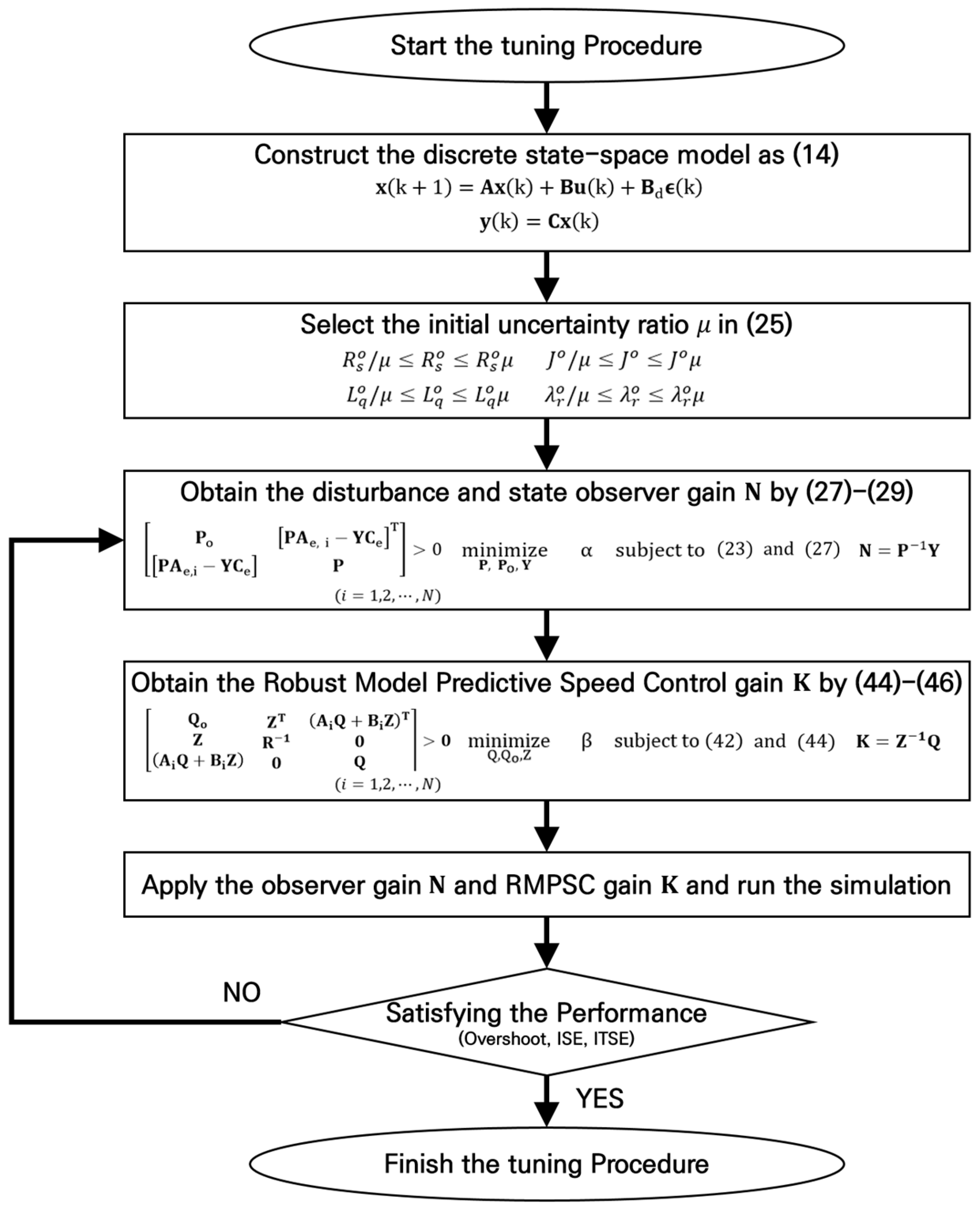
The simulation was performed with several cases and the results are presented to demonstrate the effectiveness of the proposed RMPSC method in this section. The nominal value of the PMSM parameters used in the simulation are listed in Table 1. As per the characteristics of the surface mounted PMSM used in this simulation, the stator inductance L d and L q values are the same.

5.1. Tuning Procedure μ for RMPSC

In this study, parameter uncertainties are taken into account to ensure robust control of PMSM speed against manufacturing errors or aging degradation. In (25), the range of parameter uncertainties such as stator inductance L d , stator resistance R s , rotational inertia J , and flux linkage of permanent magnets λ r are expressed with uncertainty ratio μ 1 . As mentioned in Equation (25), we consider uncertainties for four parameters, so the total number of corner points of uncertainty Ω is 16. Based on uncertainty ratio μ , the disturbance and state observer gain and controller gain are determined via the optimization problem with multiple LMIs in (27) and (44). In other words, the proposed RMPSC method is able to optimize control performance using uncertainty ratio μ .
A large value of μ means that the parameter values have a large range compared to the rated value. This can result in slow response characteristics because the performance of the RMPSC method must be guaranteed over parameters containing a wide range of uncertainties. Therefore, it is important to select the optimal μ value for speed control of the PMSM under various operating environments. In this paper, in order to select the optimal μ value, we compare the behavior of the PMSM according to the μ value when the reference speed value of the PMSM, which operates at an initial value of 1200 rpm, is changed to 1500 rpm at 0.5 s. In addition, the condition under which the initial disturbance value changes from 1.0 Nm to 2.0 Nm at 0.7 s is also included. The parameters of the PMSM used in this procedure are listed in Table 1. A total of five μ values were applied, and the results are shown in Figure 2.
An overshoot, undershoot, integral of squared (ISE), and integral of time-weighted squared error (ISET) were used to present the target value tracking characteristics of the PMSM according to μ as a performance index, and the results are shown in Table 2. It can be confirmed through the performance index that as the value of μ increases, the speed control performance for the reference value decreases. Considering the performance of the controller along with the parameter uncertainty, the value of μ is determined to be 1.3, and this was used in the simulations.
The process of selecting the value of μ is presented as a tuning procedure of determining μ , as shown in Figure 3.

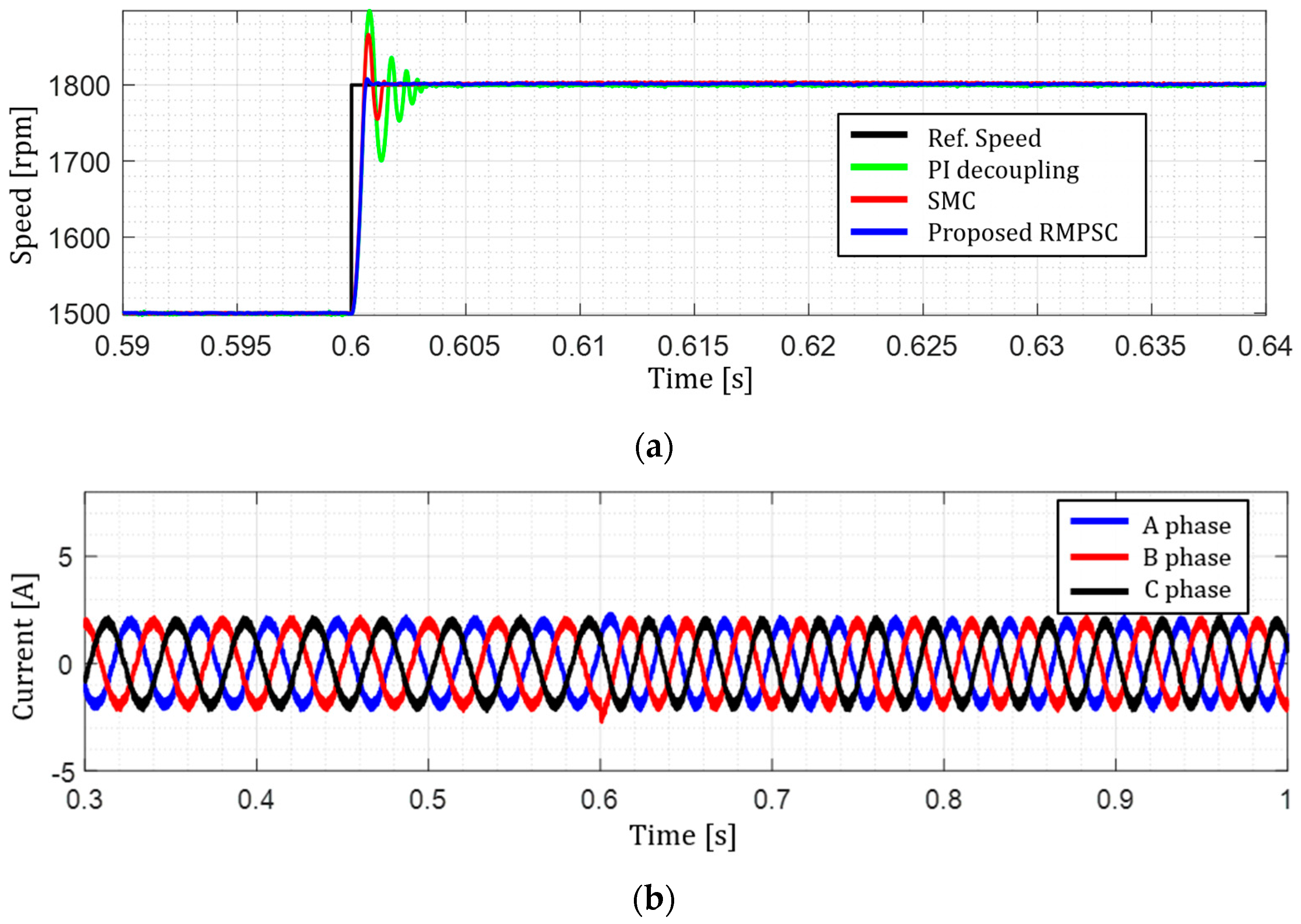
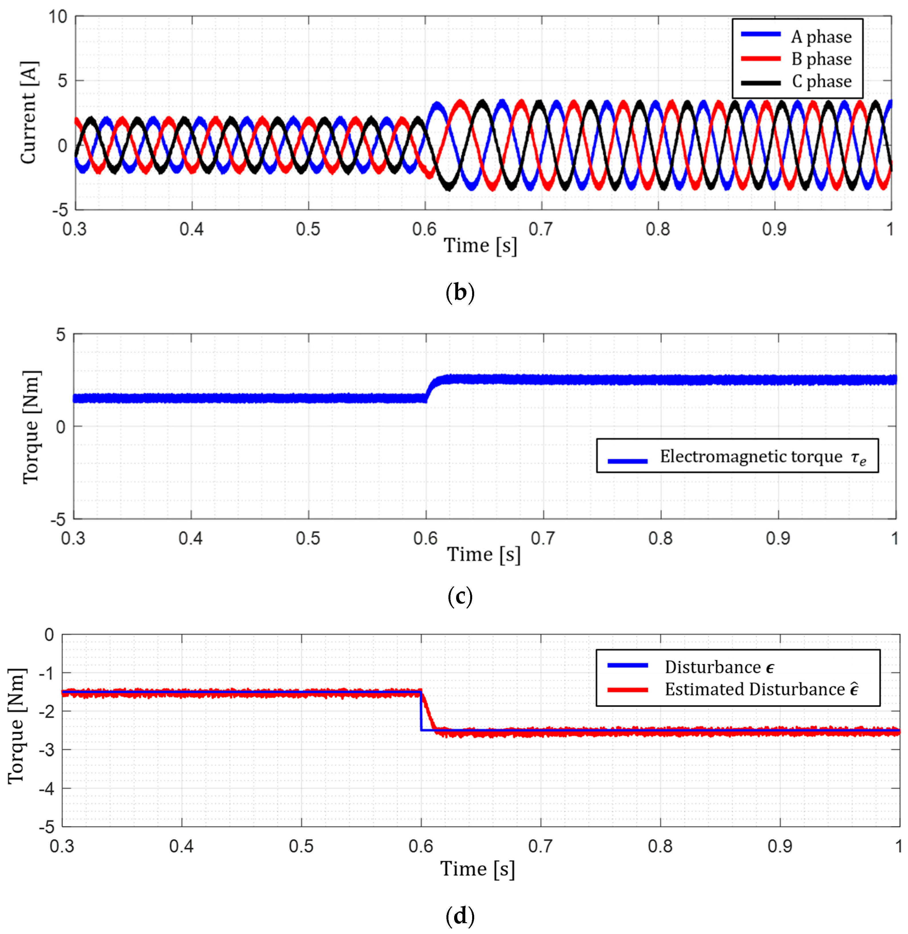
5.2. Simulation Result

To validate the proposed DOB and RMPSC, simulations were carried out under three cases. The simulation model containing the proposed method was built via MATLAB/Simulink with the optimal uncertainty μ values determined in Section 5.1. The performance of the previous method and proposed method were compared with the PI decoupling method [10] and sliding-mode method [17], respectively, and the main parameters of each controller, including the proposed RMPSC method, are shown in Table 3. The parameters of the PMSM used in the simulation are listed in Table 1.
In the first case, the reference speed ω e * of the PMSM is changed, the disturbance ϵ applied to the PMSM is fixed to a constant value, and the PMSM has nominal parameters. Figure 4 shows the comparison results of the proposed RMPSC method and comparative methods for speed control of PMSM when the reference speed ω e * of the PMSM is increased. The initial state of the PMSM is a rotation speed of 1500 rpm and a disturbance of 1.5 Nm. Figure 4 shows the simulation results for the proposed method and the comparative method when the reference speed of the PMSM is increased to 1800 rpm at 0.6 s. The speed results of the PMSM applying the proposed RMPSC and comparative methods are shown in Figure 4a. Figure 4b–d show the three-phase current of the PMSM, the electromagnetic torque value, and the disturbance ϵ ^ estimated by the DOB when the proposed RMPSC method is applied. It can be seen in Figure 4a that the speed results applying the proposed RMPSC method reach the reference speed ω e * faster than other comparative methods.
In the second case, the disturbance ϵ applied to the PMSM is changed, the reference speed ω e * of the PMSM is kept at a constant value, and the PMSM has nominal parameters. Figure 5 shows the simulation results of the proposed RMPSC and a comparative method for speed control of the PMSM when the disturbance ϵ is increased. Simulations were performed when the disturbance increases to 2.5 Nm in 0.6 s. under the same initial conditions as in the first case. The speed control results, applying the proposed method and the comparative methods, can be seen in Figure 5a. The three-phase current and electromagnetic torque values of the PMSM, and the disturbance ϵ ^ estimated by the DOB are the results of applying the proposed RMPSC method and can be confirmed in Figure 5b–d. When an additional disturbance is applied, it can be seen in Figure 5a that the proposed RMPSC method has a small speed dip and quickly recovers to the steady state ω e * compared to the other comparative methods.
In the last case, a simulation was carried out with parameter uncertainty added to the previous two cases. The initial conditions were the same as the previous cases, the disturbance ϵ and reference speed ω e * changed at each specific times, and the parameters were set to have a 20% error compared to the nominal parameters. The simulation started from the initial conditions, and the reference speed ω e * was increased to 1800 rpm at 0.5 s, and the disturbance ϵ was changed to 3.0 Nm at 0.7 s, and the results are shown in Figure 6. The speed control results adapted with the proposed and comparative methods are shown in Figure 6a, and the three-phase current and electromagnetic torque values and the estimated disturbance can be seen in Figure 6b–d, as the results of applying the proposed RMPSC method. Figure 6a shows that the proposed RMPSC method has better speed control performance compared to other comparative methods for reference speed changes and disturbances under parameter uncertainty.
To analyze the speed control performance of the proposed RMPSC method, based on simulation results for the previous three cases, the performance index is expressed as shown in Table 4. The performance index confirms that the proposed RMPSC method provides good speed control performance for a PMSM against comparative methods in three simulation cases.

6. Conclusions

This study proposes a robust model predictive speed control (RMPSC) method for the speed control of a PMSM that is robust to disturbance and parameter uncertainty. External mechanical torque, which affects the PMSM, was considered a disturbance, and this value was estimated through a disturbance observer. In addition, uncertainty in parameters was considered to ensure stable speed control performance of the PMSM under manufacturing error or aging degradation affecting the PMSM conditions. The disturbance and state observer were designed to satisfy Lyapunov stability and a cost function was constructed based on the steady state of the PMSM at the reference speed. Both the observer and controller design method were transformed into LMI-based optimization problems, and a tuning procedure of the disturbance observer, state observer, and RMPSC controller was proposed so that optimal gains could be obtained systematically. To verify the performance of the proposed methods, simulations were carried out under predefined test conditions.
The simulation results showed the effectiveness of the proposed RMPSC method in providing speed control performance to the PMSM even under conditions where the target speed changes and external disturbances are applied to the PMSM. In particular, the fast response characteristics and speed control performance were ensured by quickly estimating external disturbances through a disturbance observer, reflecting them in the RMPSC controller, and controlling the speed of the PMSM through state feedback. Furthermore, considering the uncertainty of parameters, speed control performance for the PMSM was secured even in an environment where parameters are not nominal values and optimal control performance was achieved through the proposed optimization-based systematic tuning procedure to find the optimal observer and controller gains.

Author Contributions

All of the authors contributed to publishing this paper. D.-J.K. and B.K. carried out modeling, simulation, and compiled the manuscript and literature review. All authors have read and agreed to the published version of the manuscript.

Funding

This research was funded by the Ministry of Trade, Industry, and Energy and supported by the Korea Institute of Energy Technology Evaluation and Planning (KETEP), grant number No. 20223030020110. This work was conducted under the framework of the Research and Development Program of the Korea Institute of Energy Research (KIER) (No. C4-2422).

Data Availability Statement

The data presented in this study are available on request from the corresponding author. The data are not publicly available due to for result test using the equipment owned by our institute.

Conflicts of Interest

The authors declare no conflicts of interest.

References

  1. Mohanraj, D.; Gopalakrishnan, J.; Chokkalingam, B.; Mihet-Popa, L. Critical Aspects of Electric Motor Drive Controllers and Mitigation of Torque Ripple—Review. IEEE Access 2022, 10, 73635–73674. [Google Scholar] [CrossRef]
  2. Yang, J.; Chen, W.-H.; Li, S.; Guo, L.; Yan, Y. Disturbance/Uncertainty Estimation and Attenuation Techniques in PMSM Drives—A Survey. IEEE Trans. Ind. Electron. 2017, 64, 3273–3285. [Google Scholar] [CrossRef]
  3. Hasoun, M.; Afia, A.E.; Khafallah, M. Performance Comparison of Two-SVPWM-Strategies Based Vector Space Decomposition Controlled Dual Three-Phase PMSM for Electric Ship Propulsion. In Proceedings of the 2019 7th International Renewable and Sustainable Energy Conference (IRSEC), Agadir, Morocco, 27–30 November 2019; pp. 1–8. [Google Scholar]
  4. Hori, S.; Doki, S. Examination of Current Sensor Fail-Safe of PMSM current control system which using current and position state estimation techniques. In Proceedings of the 2020 23rd International Conference on Electrical Machines and Systems (ICEMS), Hamamatsu, Japan, 24–27 November 2020; pp. 694–698. [Google Scholar]
  5. Yuan, T.; Wang, D.; Wang, X.; Wang, X.; Sun, Z. High-Precision Servo Control of Industrial Robot Driven by PMSM-DTC Utilizing Composite Active Vectors. IEEE Access 2019, 7, 7577–7587. [Google Scholar] [CrossRef]
  6. Gong, C.; Hu, Y.; Gao, J.; Wu, Z.; Liu, J.; Wen, H.; Wang, Z. Winding-Based DC-Bus Capacitor Discharge Technique Selection Principles Based on Parametric Analysis for EV-PMSM Drives in Post-Crash Conditions. IEEE Trans. Power Electron. 2021, 36, 3551–3562. [Google Scholar] [CrossRef]
  7. Liu, Y.-C.; Laghrouche, S.; Depernet, D.; Djerdir, A.; Cirrincione, M. Disturbance-Observer-Based Complementary Sliding-Mode Speed Control for PMSM Drives: A Super-Twisting Sliding-Mode Observer-Based Approach. IEEE J. Emerg. Sel. Top. Power Electron. 2021, 9, 5416–5428. [Google Scholar] [CrossRef]
  8. Novak, Z.; Novak, M. Adaptive PLL-Based Sensorless Control for Improved Dynamics of High-Speed PMSM. IEEE Trans. Power Electron. 2022, 37, 10154–10165. [Google Scholar] [CrossRef]
  9. Apte, A.; Joshi, V.A.; Mehta, H.; Walambe, R. Disturbance-Observer-Based Sensorless Control of PMSM Using Integral State Feedback Controller. IEEE Trans. Power Electron. 2020, 35, 6082–6090. [Google Scholar] [CrossRef]
  10. Zhu, H.; Xiao, X.; Li, Y. PI type dynamic decoupling control scheme for PMSM high speed operation. In Proceedings of the 2010 Twenty-Fifth Annual IEEE Applied Power Electronics Conference and Exposition (APEC), Palm Springs, CA, USA, 21–25 February 2010; pp. 1736–1739. [Google Scholar]
  11. Sant, A.V.; Rajagopal, K.R. PM Synchronous Motor Speed Control Using Hybrid Fuzzy-PI with Novel Switching Functions. IEEE Trans. Magn. 2009, 45, 4672–4675. [Google Scholar] [CrossRef]
  12. Li, H.; Song, B.; Chen, T.; Xie, Y.; Zhou, X. Adaptive fuzzy PI controller for permanent magnet synchronous motor drive based on predictive functional control. J. Frankl. Inst. 2021, 358, 7333–7364. [Google Scholar] [CrossRef]
  13. Guo, J.; Fan, T.; Li, Q.; Wen, X. An Angle-Compensating, Complex-Coefficient PI Controller Used for Decoupling Control of a Permanent-Magnet Synchronous Motor. Symmetry 2022, 14, 101. [Google Scholar] [CrossRef]
  14. Zeng, X.; Wang, W.; Wang, H. Adaptive PI and RBFNN PID Current Decoupling Controller for Permanent Magnet Synchronous Motor Drives: Hardware-Validated Results. Energies 2022, 15, 6353. [Google Scholar] [CrossRef]
  15. Wang, Y.; Feng, Y.; Zhang, X.; Liang, J. A New Reaching Law for Antidisturbance Sliding-Mode Control of PMSM Speed Regulation System. IEEE Trans. Power Electron. 2020, 35, 4117–4126. [Google Scholar] [CrossRef]
  16. Jiang, Y.; Xu, W.; Mu, C.; Liu, Y. Improved Deadbeat Predictive Current Control Combined Sliding Mode Strategy for PMSM Drive System. IEEE Trans. Veh. Technol. 2018, 67, 251–263. [Google Scholar] [CrossRef]
  17. Liao, Z.; Hao, Y.; Guo, T.; Lv, B.; Wang, Q. Second-Order Sliding Mode Control of Permanent Magnet Synchronous Motor Based on Singular Perturbation. Energies 2022, 15, 8028. [Google Scholar] [CrossRef]
  18. Leu, V.Q.; Choi, H.H.; Jung, J.W. Fuzzy sliding mode speed controller for PM synchronous motors with a load torque observer. IEEE Trans. Power Electron. 2012, 27, 1530–1539. [Google Scholar] [CrossRef]
  19. Bao, G.; Qi, W.; He, T. Direct Torque Control of PMSM with Modified Finite Set Model Predictive Control. Energies 2020, 13, 234. [Google Scholar] [CrossRef]
  20. Zhang, Y.; Xu, D.; Huang, L. Generalized multiple-vector-based model predictive control for pmsm drives. IEEE Trans. Ind. Electron. 2018, 65, 9356–9366. [Google Scholar] [CrossRef]
  21. Xie, W.; Wang, X.; Wang, F.; Xu, W.; Kennel, R.M.; Gerling, D.; Lorenz, R.D. Finite-Control-Set Model Predictive Torque Control With a Deadbeat Solution for PMSM Drives. IEEE Trans. Ind. Electron. 2015, 62, 5402–5410. [Google Scholar] [CrossRef]
  22. Wang, Y.; Fang, S.; Hu, J.; Huang, D. A Novel Active Disturbance Rejection Control of PMSM Based on Deep Reinforcement Learning for More Electric Aircraft. IEEE Trans. Energy Convers. 2023, 38, 1461–1470. [Google Scholar] [CrossRef]
  23. Wang, Y.; Fang, S.; Hu, J.; Huang, D. Multiscenarios Parameter Optimization Method for Active Disturbance Rejection Control of PMSM Based on Deep Reinforcement Learning. IEEE Trans. Ind. Electron. 2023, 70, 10957–10968. [Google Scholar] [CrossRef]
  24. Abu-Ali, M.; Berkel, F.; Manderla, M.; Reimann, S.; Kennel, R.; Abdelrahem, M. Deep Learning-Based Long-Horizon MPC: Robust, High Performing, and Computationally Efficient Control for PMSM Drives. IEEE Trans. Power Electron. 2022, 37, 12486–12501. [Google Scholar] [CrossRef]
  25. Apte, A.; Joshi, A.; Walambe, R.A.; Godbole, A. Speed Control of PMSM Using Disturbance Observer. IFAC-PapersOnLine 2016, 49, 308–313. [Google Scholar] [CrossRef]
  26. Singh, S.; Singh, S.; Tiwari, A. PMSM drives and its application: An overview. Recent Adv. Elect. Electron. Eng. Former. Recent Pat. Elect. Electron. Eng. 2023, 16, 4–16. [Google Scholar] [CrossRef]
  27. Mahmoud, M.S.; Huynh, V.K.; Senanyaka, J.S.L.; Robbersmyr, K.G. Robust Multiple-Fault Diagnosis of PMSM Drives Under Variant Operations and Noisy Conditions. IEEE Open J. Ind. Electron. Soc. 2023, 4, 762–772. [Google Scholar] [CrossRef]
  28. Sun, X.; Yi, Y.; Cao, S.; Liu, H.; Zhang, T. Robust PI-type position controller design for permanent magnet synchronous motor using LMI techniques. In Proceedings of the 2015 Chinese Intelligent Automation Conference: Intelligent Automation, Fuzhou, China, 8–10 May 2015; Lecture Notes in Electrical Engineering. Springer: Berlin/Heidelberg, Germany, 2015; Volume 337, pp. 405–412. [Google Scholar]
  29. Franklin, G.F.; Powell, J.D.; Workman, M. Digital Control of Dynamic Systems; Addison Wesley Longman: Reading, MA, USA, 1997. [Google Scholar]
  30. Boyd, S.P.; Ghaoui, L.E.; Feron, E.; Balakrishnan, V. Linear Matrix Inequalities in System and Control Theory; SIAM: Philadelphia, PA, USA, 1994. [Google Scholar]
Figure 1. Block diagram of the proposed RMPSC method with a disturbance observer.
Energies 17 00869 g001
Figure 2. Simulation results of the dynamic response of the PMSM when changing the reference speed value ω e * and disturbance ϵ according to μ values: (a) Speed results of the PMSM according to the proposed RMPSC, (b) measured disturbance ϵ and estimated disturbance ϵ ^ using the DOB.
Energies 17 00869 g002
Figure 3. Tuning procedure to obtain the optimal gains by determining μ .
Energies 17 00869 g003
Figure 4. Simulation results of the dynamic response of the PMSM when changing the reference speed value ω e * : (a) Speed results of the PMSM applying the PI-decoupling method, sliding mode control method, and proposed RMPSC method, respectively, (b) the three-phase current of the PMSM under the proposed RMPSC method, (c) the electromagnetic torque τ e of the PMSM under the proposed RMPSC method, (d) the measured disturbance ϵ and estimated disturbance ϵ ^ according to the DOB.
Energies 17 00869 g004aEnergies 17 00869 g004b
Figure 5. Simulation results of the dynamic response of the PMSM when disturbance ϵ changes in the PMSM: (a) speed results of the PMSM applying the PI-decoupling method, sliding-mode control method, and proposed RMPSC method, respectively, (b) the three-phase current of the PMSM under proposed the RMPSC method, (c) the electromagnetic torque τ e of the PMSM under the proposed RMPSC method, (d) the measured disturbance ϵ and estimated disturbance ϵ ^ according to the DOB.
Energies 17 00869 g005aEnergies 17 00869 g005b
Figure 6. Simulation results of the dynamic response of the PMSM when disturbance ϵ changes in the PMSM with parameter uncertainty: (a) speed results of the PMSM applying the PI-decoupling method, sliding-mode control method, and the proposed RMPSC method, respectively, (b) the three-phase current of the PMSM under the proposed RMPSC method, (c) the electromagnetic torque τ e of the PMSM under the proposed RMPSC method, (d) the measured disturbance ϵ and estimated disturbance ϵ ^ according to the DOB.
Energies 17 00869 g006
Table 1. System Parameters.
SymbolDescriptionValueUnit
P n Rated Power0.4kW
L d ( = L q ) Stator Inductance6.71mH
R s Stator Resistance1.55ohm
λ r Flux Linkage of Permanent Magnets0.175Wb
F Viscous Friction Coefficient0.0003Nms
J Rotational Inertia0.0002 k g · m 2
P Pole Pairs3-
T s Sampling Time100μs
Table 2. Tuning result of the proposed RMPSC method: PMSM speed control.
μ Overshoot [rpm]Undershoot [rpm]ISEITSE
1.01570149626.9052.690 × 10−4
1.31510149525.9052.590 × 10−4
1.51505149326.4462.644 × 10−4
1.71502149132.0453.204 × 10−4
2.01501148645.4514.545 × 10−4
Table 3. Main parameters of each controller.
ControllerDescriptionValue
PI decoupling [10]P gain/I gain7/600
SMC [17]k1/k21000/200
SMC [17]P gain/I gain3/200
Proposed RMPCSUncertainty μ1.3
Proposed RMPCSWeighting R1.2 × 10−4
Table 4. Performance index comparison results for PMSM speed control.
MethodISEITSE
PI-decoupling [10]71.2837.128 × 10−4
Sliding Mode Control [17]56.08395.608 × 10−4
Proposed RMPSC55.02235.502 × 10−4
Disclaimer/Publisher’s Note: The statements, opinions and data contained in all publications are solely those of the individual author(s) and contributor(s) and not of MDPI and/or the editor(s). MDPI and/or the editor(s) disclaim responsibility for any injury to people or property resulting from any ideas, methods, instructions or products referred to in the content.

