Article

Optimal Reactive Power Flow of AC-DC Power System with Shunt Capacitors Using Backtracking Search Algorithm

1
Department of Mathematics and Statistics, College of Science, King Faisal University, Hafuf 31982, Saudi Arabia
2
Electrical and Electronics Engineering Department, Girne American University, Kyrenia 99428, Turkey
*
Author to whom correspondence should be addressed.
Energies 2024, 17(3), 749; https://doi.org/10.3390/en17030749
Submission received: 28 December 2023 / Revised: 26 January 2024 / Accepted: 1 February 2024 / Published: 5 February 2024
(This article belongs to the Section F3: Power Electronics)

Abstract

:
In this paper, it is proposed that a two-terminal high voltage direct current (HVDC) be integrated into the power system. Line-commutated converter (LCC)-HVDC is used because of its ability to reduce line losses, which improves overall system efficiency. Shunt capacitors also aid in voltage maintenance by compensating for the reactive power demand. In essence, limiting voltage drops in electrical networks promotes a more efficient power transmission and distribution by lowering resistive losses. In power system investigations, it was discovered that the HVDC link and SCB exist separately. So, for the first time, the backtracking search algorithm (BSA) is used to solve the optimal reactive power flow (ORPF) of a power system with a HVDC link and shunt capacitor banks (SCB). Although BSA simulations on a modified IEEE 30 bus yielded successful results, ABC was also utilized for comparing the outcomes of different methods. Overall, three separate cases of the modified IEEE 30 bus system were examined. When the acquired results are compared to other methods, the suggested algorithm is found to be better at concerning effectiveness as well as performance.

1. Introduction

As the world’s population continues to rise, more homes, companies, and industries use electricity for a variety of functions, such as lighting, cooling, heating, other equipment, and industrial activities [1]. Increasing the load causes a higher current flow, more resistance heating in power transmission lines, and an increasing voltage drop, all of which reduce the efficiency as well as the reliability of electric power transmission lines [2]. When the load exceeds the system limit, the chance of a system outage increases. To solve these issues, shunt capacitor banks (SCB) and HVDC are proposed.
When SCBs are used in power systems, they offer a variety of effects and benefits. These advantages include reactive power compensation, loss reduction, increased transmission capacity, and improved power quality [3]. SCBs aid in boosting voltage by eliminating voltage dips and increasing voltage stability. Voltage levels can be kept within acceptable limits by compensating for reactive power, especially during periods of heavy load demand. This prevents voltage drops and offers a stable and dependable power source. Shunt capacitors help to reduce power losses in power systems [3]. The system’s apparent power requirement is decreased by correcting for the reactive power. As a result, the I2R losses associated with transmission and distribution lines, transformers, and other components are reduced [4].
When compared to traditional optimization techniques, heuristic optimization algorithms can generate the best solution for the location and sizing of SCBs in distribution networks [5]. To optimize the position of the SCBs in power systems, many methods and methodologies have been utilized. For example, ref. [5] used a hybrid of the harmony search algorithm (the) and Particle Artificial Bee Colony algorithm (PABC), ref. [6] implemented Integrated Deferred-Merge Embedding (IDME), ref. [7] utilized multi-objective particle swarm optimization (MOPSO), ref. [8] employed the Bacterial Foraging Optimization Algorithm (BFOA), ref. [9] implemented the Fuzzy Genetic Algorithm (FGA), ref. [10] employed PSO, ref. [11] proposed an analytical approach, ref. [12] used the Memetic algorithm (MA), ref. [13] utilized a hybrid of the imperialist competitive algorithm (ICA) and GA, ref. [14] used A hybrid of ABC with evolution algorithm (EA), and ref. [15] applied a backtracking search algorithm (BSA). Ref. [16] used System-based testing methodologies for protection systems which were implemented using Relaysimtest software, which is compatible with OMICRON injection test sets. Ref. [17] applied a genetic algorithm developed for the optimum planning of shunt capacitor banks. Ref. [18] used GA, PSO, Bat Optimization Algorithm (BOA), and the Whale Optimization Algorithm (WOA) and the Sperm-Whale Algorithm (SWA).
Many countries are beginning to employ HVDC transmission in their systems thanks to its many positive effects. The advantages of the HVDC link include cost-effective long-distance power transmission, improved grid stability, and the opportunity to integrate renewable energy sources [19]. Although HVDC has advantages in some instances, it should be noted that HVDC installations are often more expensive than HVAC systems [19]. As a result, the decision to adopt HVDC in a power system is influenced by several factors, including transmission distance, system needs, and economic considerations.
LCC (Line Commutated Converter) and VSC (Voltage Source Converter) represent two forms of HVDC (High Voltage Direct Current) systems employed for long-distance power transmission or connecting asynchronous AC (Alternating Current) systems.
LCC-HVDC is appropriate for the long-distance transmission of power but has limited capacity for reactive power and is less expensive, whereas VSC-HVDC has better controllability but is more expensive.
Table 1 demonstrates some of recent findings that have considered the HVDC in the last few years [20,21,22,23,24,25,26,27,28,29,30,31,32].
Optimal reactive power flow research has concentrated on developing algorithms and approaches for optimizing reactive power flow in AC-DC hybrid grids. These insights help to manage reactive electricity more efficiently, reduce losses, and improve overall grid efficiency. The optimal reactive power flow in a power system is the process of determining the most efficient and cost-effective distribution of the reactive power sources in order to keep system voltages within acceptable limits.
Scientists have used a variety of approaches to solve the optimal reactive power flow problem in hybrid AC-DC systems [20,22,24,25,29,31]. The reference [20] employed FDB-SFS in a power system with HVDC links to reduce power loss, improve voltage variation, and save costs. In ref. [22], GA was used to reduce power loss in an alternating current–direct current system. In ref. [24], DENM was utilized in power systems with hybrid AC-DC systems to reduce power loss [25]. The PF algorithm was used to minimize losses in an AC-DC system. In ref. [29], SDP is used in AC-DC systems to reduce power loss. In ref. [31], BSA was utilized in a hybrid AC-DC system to reduce power loss and costs. In ref. [33], power flow was used as a systematic way to compare the HVDC and HVDC systems based on power loss. In [34], the Songo–Apollo link was used to network model with DIgSILENT Power Factory software (made by DIgSILENT GmbH in Gomaringen, Germany) in a system with HVDC and flexible alternating current technology systems (FACTS). In [35], the Teaching Learning-Based Algorithm (TLBA) was used to reduce both system power losses and fuel costs.
During system disturbances, capacitors can aid by offering voltage support. Capacitors are able to release their stored energy to help maintain the DC voltage level in the case of a voltage dip or sag in the AC system. This increases system stability and helps to reduce voltage swings.
In this article, the backtracking search algorithm will be used to configure three shunt capacitors and an LCC-HVDC link in an IEEE 30 bus system. This work is completed in three different scenarios to demonstrate the effects of SCB and LCC-HVDC. Another approach was used for comparison with the proposed method, and results from both methods were compared and analyzed.
The paper is organized into five sections. Section 1 starts with an introduction, which included a literature review on the shunt capacitor bank and HVDC link in the power system. Section 2 discusses materials and methods which are AC and DC system modeling, objective function, and fitness function. Section 3 includes a backtracking search algorithm construction, pseudo, and flow chart. Section 4 presents the paper’s results and discussions, and Section 5 presents the paper’s conclusions.

2. Materials and Methods

The mathematical representation of the single objective optimization problems under consideration is as follows:
Minimize   f ( x , u ) Subject   to   g ( x , u ) = 0 h ( x , u ) 0
where g represents the equality constraints, h depicts the inequality constraints, x and u are state and control parameters, respectively, and f denotes the objective functions to be minimized. The state and control variables of an optimization problem for a two-terminal HVDC system are taken into account as in [28].
Figure 1 depicts the basic configuration of a two-terminal HVDC scheme, which consists of two converters connected by a DC link [22]. The rectifier (with abbreviation r) and inverter (with abbreviation i) are linked to AC system buses.
Figure 2 depicts the equivalent circuit for the two terminal HVDC link.
The following are the equations linked to a converter’s rectifier operation [36,37]:
V dor = 3 2 Π V r t r
V dr = V dor cos α 3 X cr Π I d
where V dor represents the optimum no-load direct voltage and α is the ignition delay angle. The equivalent commutating reactance X cr accounts for the voltage drop caused by a commutation overlap. The rectifier side’s active power is determined by:
P dr = V dr I d
On the rectifier side, the reactive power is calculated as follows:
Q dr = P dr tan Φ r
where Φ r is the phase angle separating the alternating current and voltage, and is determined as follows:
Φ r = cos 1 V dr V dor
The formulas relating to a converter’s inverter operating are as follows:
V doi = 3 2 Π V i t I
V di = V doi cos γ 3 X ci Π I d
P di = V di I d
Q di = P di tan Φ i
Φ i = cos 1 V di V doi
The relationship between the two DC voltages can be represented as:
V dr = V di + R dc I d

2.1. The State and Control Variables of DC and AC System

The following AC and DC system state (x) and control variables (u) have been determined as follows:
x = p gslack ,   q g 1 , , q g N g ,   v L 1 , , v L N l t r ,   t i ,   α r ,   α i , v dr , v di
The AC and DC system control variables per unit are also selected as follows:
u A C = [ p g 2 , , p g N g ,   v g 1 , , v g N g , t 1 , , t N T , q c 1 , , q c N c , q c b 1 , , q c b 3 , l o c 1 , , l o c 3 p dr ,   p di ,   q dr ,   q di , i d ]

2.2. Power Loss

The objective of minimizing power line losses is mathematically represented by the following:
Ploss = i = 1 N g n p g n g i j = 1 N p l d j
where N is the total number of system buses and p l d j denotes the active load of jth bus, respectively.
System restrictions on equality and inequality.
Each bus’s equality restrictions include active and reactive power balancing [22]. The active–reactive power of the generators, voltage magnitude, transformer tap, and reactive compensator limits are the inequality constraints, as shown in (16)–(21) [28].
The HVDC line parameters’ limitations of inequality (minimum and maximum limits) can be seen below [22]:
p g m min p g m p g m max   m = 1 , , N g
q c b m min q c b m q c b m max   m = 1 , , N b
v m min v m v m max   m = 1 , , N
q g m min q g m q g m max   m = 1 , , N g
q c m min q c m q c m max   m = 1 , , N c
t m min t m t m max   m = 1 , , N T
The HVDC line parameters’ limitations of inequality (minimum and maximum limits) can be seen below [22,31]:
p d k min p d k p d k max   k = r , i
v d k min v d k v d k max   k = r , i
q d k min q d k q d k max   k = r , i
t d k min t d k t d k max   k = r , i
α k min α k α k max   k = r , i
i d min i d i d max

2.3. Fitness Function

To deal with the inequality constraints associated with state variables, they can be integrated as the quadratic penalty factors in the objective function. The following enhanced objective function then describes the fitness function:
Fitness = objective + i k e k i Δ x i
where Δ x is the difference between the state variable and its limit, ki is the penalty factor, and ke is the number of state variables.

3. Backtracking Search Algorithm

The backtracking search algorithm (BSA) is a generic algorithmic strategy for solving combinatorial issues. When compared to other algorithms, BSA has a much simpler structure. BSA is capable of solving nonlinear, nonconvex, and difficult optimization problems. This algorithm’s most essential quality is that it is not very sensitive to the parameter’s starting value [38]. The proposed approach has been used successfully to address issues in a variety of technical domains [38,39,40,41]. Ref. [42] provides a detailed description of the BSA pseudo code.
BSA employs a random mutation technique, selecting individuals from the previous generation at random, and employing a non-uniform crossover mechanism [42].
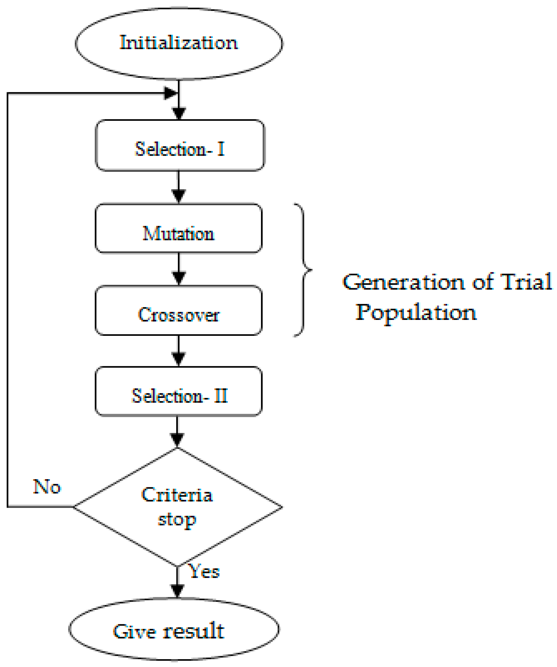
The proposed algorithm’s functions can be divided into five steps, including initialization, selection I, mutation, crossover, and selection II.
Figure 3 depicts the BSA’s flow chart.
The basic steps of the BSA are outlined as follows [42]:
Initialization
At first, two distinct populations ( Pop and oldPop ) develop as follows:
Pop i , j ~ Rand low j , up j   i = 1 , , S N     j = 1 , , D
oldPop i , j ~ Rand low j , up j   i = 1 , , S N     j = 1 , , D
Selection-1
The old population ( oldPop ) at the initial step is formed in this section employing:
i f   a < b ,     oldPop : = Pop   end |   a , b ~ Rand 0 , 1
The update operator in Equation (31) is :=. This operator transfers variables from Pop persons to oldPop individuals at random. Then, Equation (32) is used to alter individuals in the oldPop as random as follows:
oldPop : = Randshuff ( oldPop )
where Randshuff represents a random mixing tool.
Mutation
As a result of the mutation process,
mutant Pop = Pop + W oldPop Pop
The amplitude of the search line matrix is controlled by W in Equation (33). The goal here is to partially process the preceding generation’s experience. The function “ randn ” creates random numbers between 0 and 1 using ordinary normal distribution.
Crossover
The trial population ( Tpop ) is generated in this step using Equation (34). The crossover procedure is divided into two steps. The binary number system is completely valued in the first stage, yielding the S N D size of a matrix (map). This matrix is used to decide whether we need to change Tpop one row at a time (“individually by individual” in heuristic expressions). After forming the matrix, the second stage yields the following equation:
if   map i , j = 1   then   Tpop i , j = Pop i , j   else   Tpop i , j = mutant Pop i , j   end
The mutation technique utilizes a single individual from a previous population, but the BSA’s crossover mechanism is more complicated than that of the differential evolution algorithm and developed versions [42].
Selection-II
This part computes all of the “individual” fitness values generated. Individuals are ranked the from best to worst in terms of fitness. The SN of them is then transmitted to the following iteration, Pop . The rest are omitted. The best “individuals” from the entire population are thus passed down to the next generation.

4. Results and Discussion

The proposed algorithm was implemented in the IEEE 30 bus system [43]. This study takes into account three separate cases by BSA (Method 1) and ABC (Method 2). The cases include:
Case 1: The standard system.
Case 2: Three SCBs configured in the default system.
Case 3: Configuration of three SCBs with HVDC at lines (2–14).
Case 1: The power flow is applied in the passive test system, and the results are given in Table 2.
Case 2:
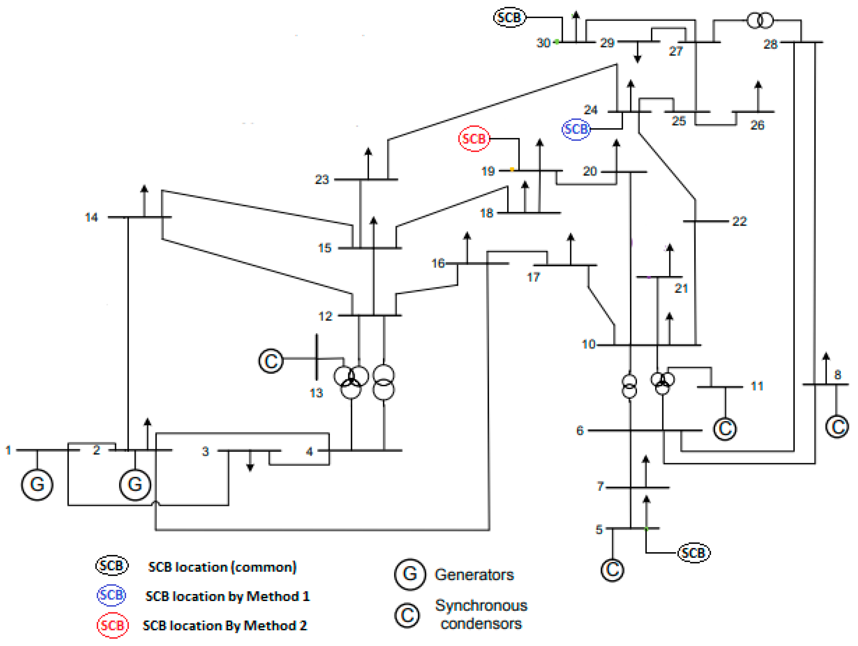
A total of three shunt capacitors are integrated into the test system in this scenario, as shown in Figure 4. The total reactive power injected by three SCBs in the buses 5, 24, and 30 using Method 1 is 10.0 MVAR for each unit, whereas the capacitors used in Method 2 are placed in the buses (5, 19, and 30) with capacities of 9.5, 10, and 10 MVAR, respectively. The results of Method 1 and Method 2 for Case 2 of the test system are compared.
Methods 1 and 2 reduced power loss by 63.49% and 62.74%, respectively, based on the default setup. Table 2 shows the outcome of Case 2.
Case 3:
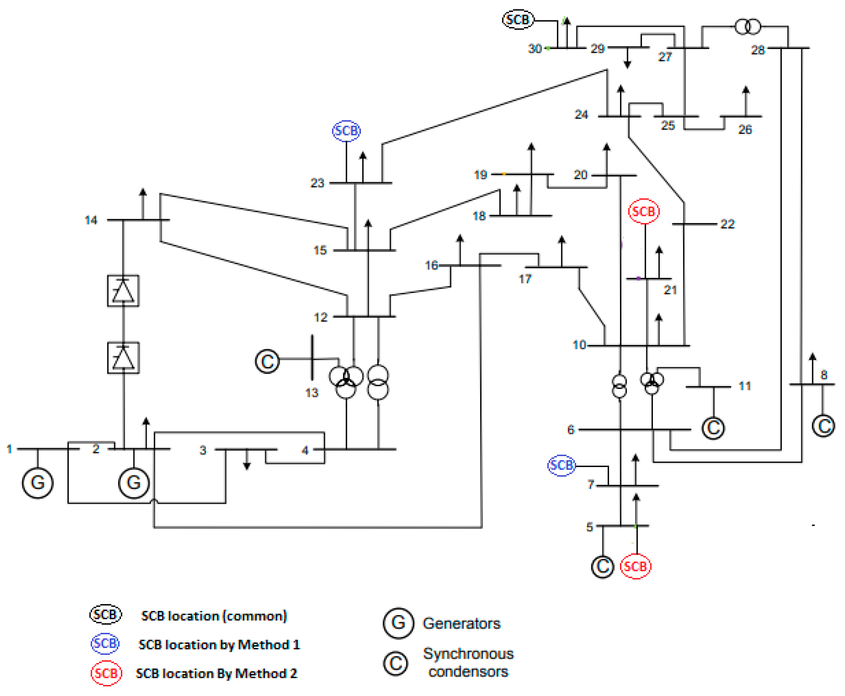
In this case, three SCBs have been installed in the test system, with an HVDC link connecting bus 2 and 14. The total reactive power injected by three SCBs in buses 7, 23, and 30 using Method 1 is 10.0, 10.0, and 9.0 MVAR, respectively, whereas the capacitors used in Method 2 are located in buses 5, 21, and 30, with capacities of 8.75, 9.5, and 8.5 MVAR. Method 1 and Method 2 outcomes for Case 3 of the test system are compared.
Based on the default configuration, Methods 1 and 2 reduced power loss by 64.21% and 63.78%, respectively. Case 3’s outcome is shown in Figure 5 and Table 3.
The DC parameters and their limit values are shown in Table 4. All DC parameter values are within their ranges.
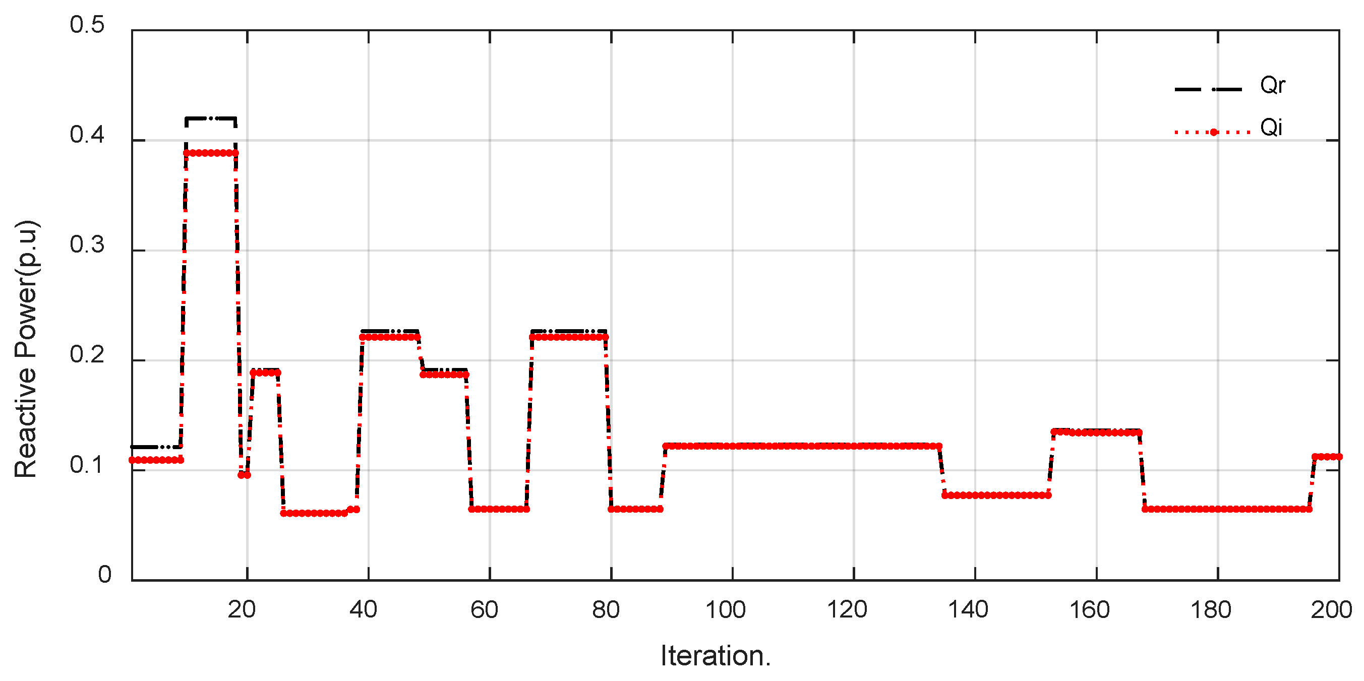
Figure 6 depicts variations in reactive power at the rectifier and inverter sides versus iteration number for Case 3. The reactive powers are clearly within the limits as shown in Figure 6.
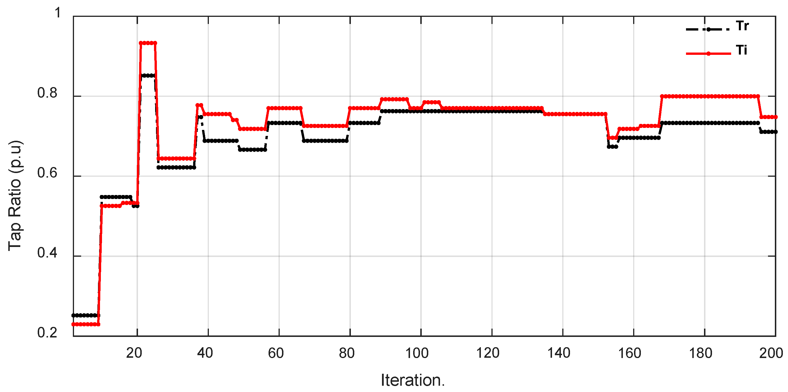
Figure 7 shows variations in the transformer tap rate at the rectifier and inverter sides versus iteration number for Case 3. The transformer tap ratios are clearly within the limits as shown in Figure 7.
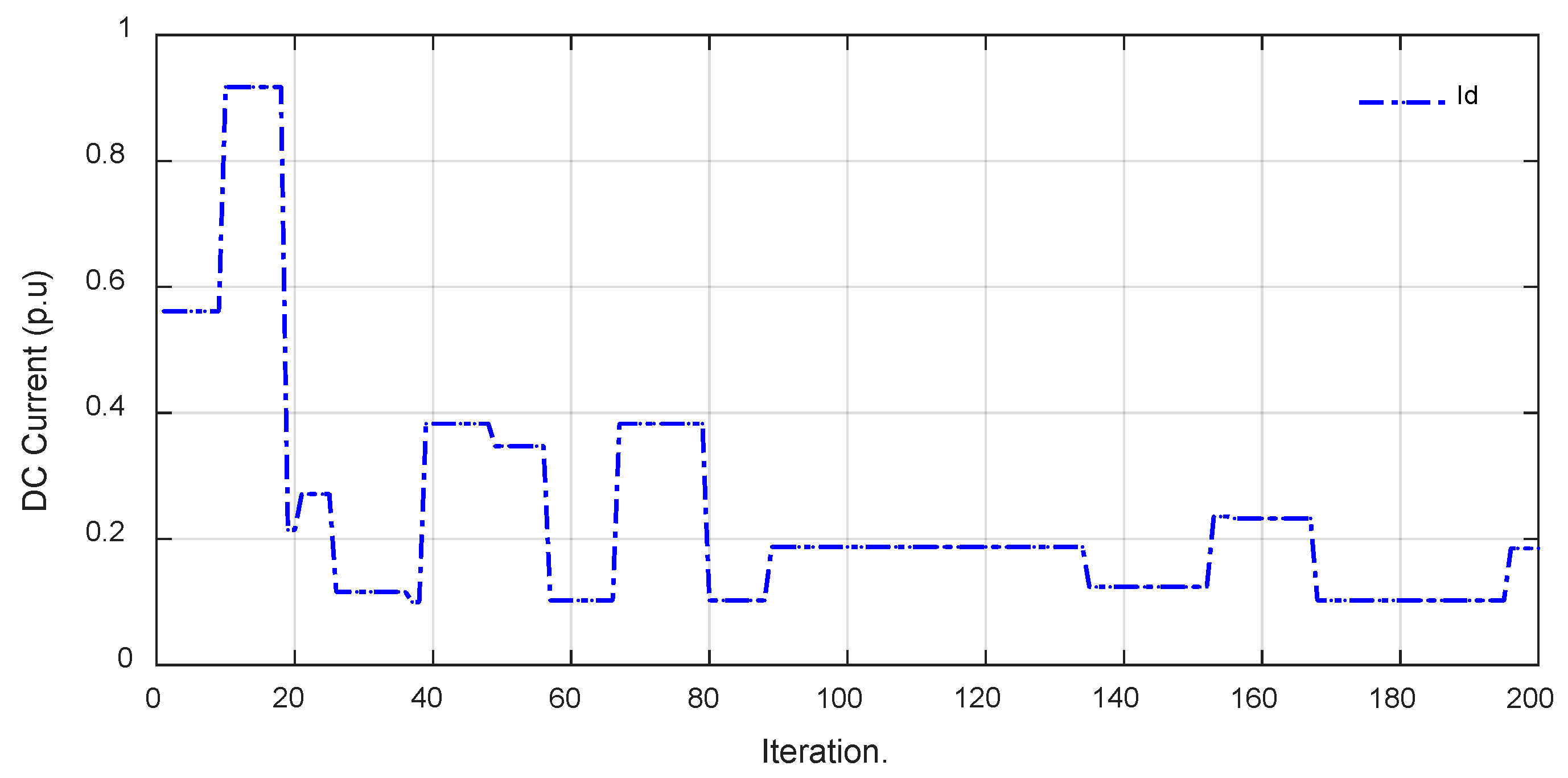
Figure 8 illustrates variations in the DC current in HVDC link versus iteration number for Case 3. The DC current is clearly within the limits as shown in Figure 8.
The analysis in Table 5 revealed that four lines had losses greater than 3.75 kW: 1–2, 1–3, 2–5, and 2–6. This demonstrates that adding the three SCBs, as in Case 2, reduced the number of lines with losses of more than 5 kW in some lines. The improved system had a 16.254 kW difference in real power for Case 2, and a 16.4383 kW difference in real power for Case 3.
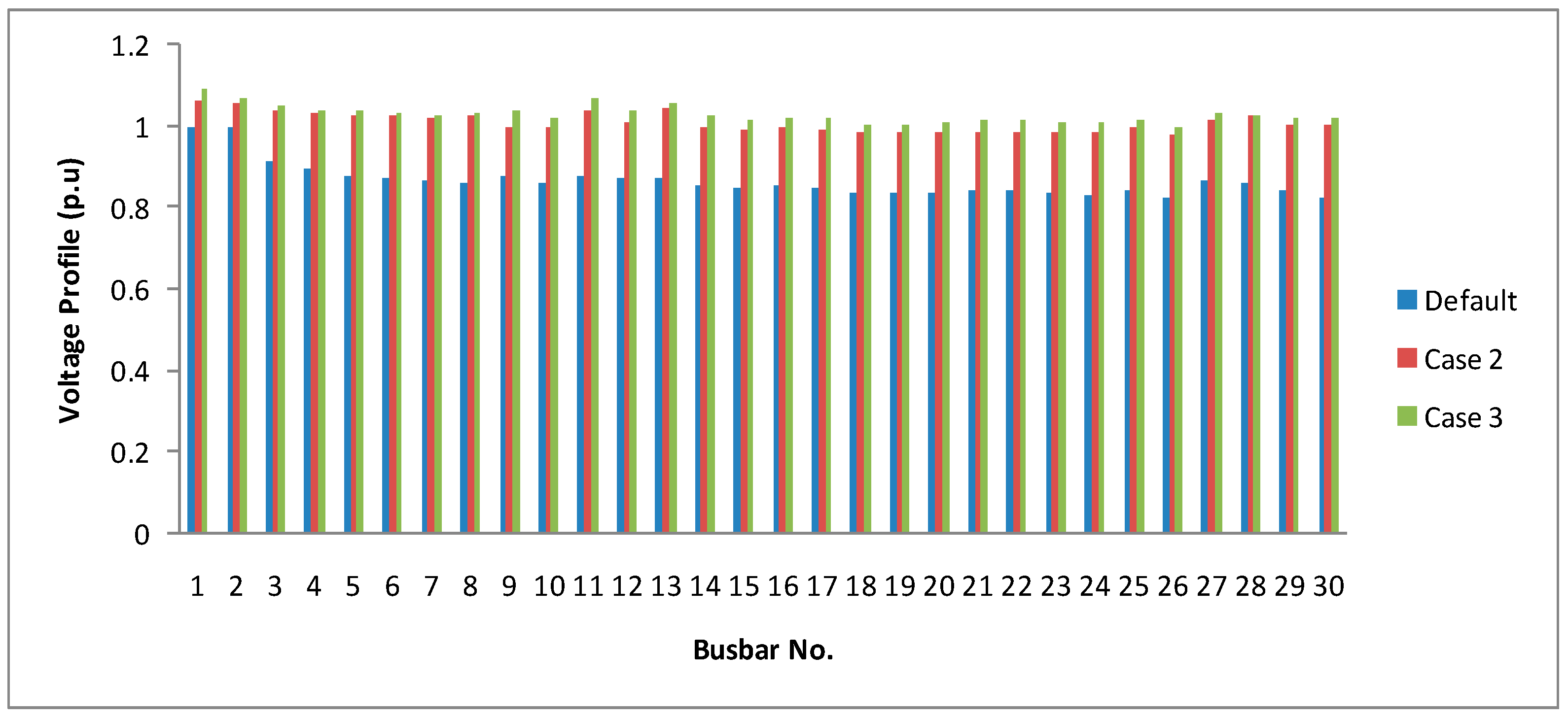
It is possible to see a considerable improvement in the bus voltage profile in Cases 2 and 3 when compared to the default. The bus voltage profile is enhanced with integrated SCBs (Case 2) and integrated SCBs with a hybrid system (Case 3), as shown in Figure 9, and all voltages are within their limitations.
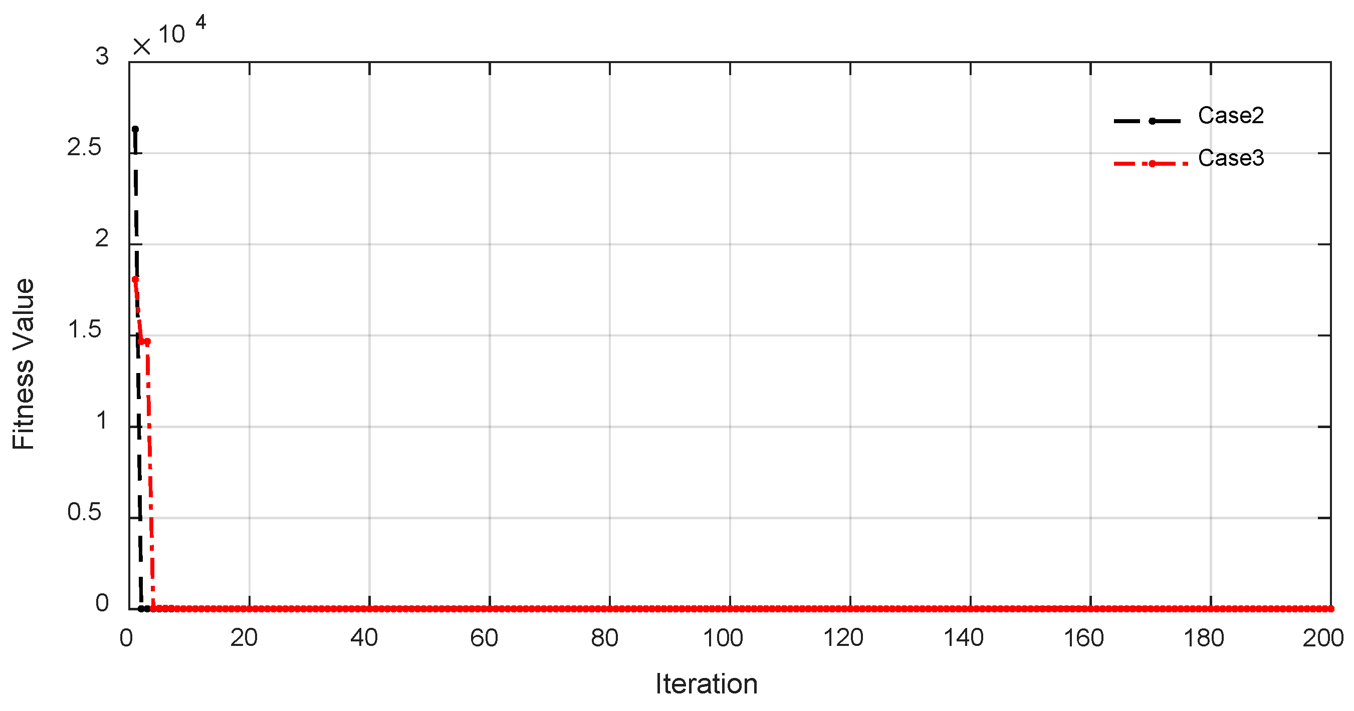
Figure 10 depicts the fitness value variations in the Hybrid test system against iteration number for Cases 2 and 3.

5. Conclusions

This paper presents a thorough investigation of the LCC-HVDC link and SCBs that have been integrated with conventional power systems. The LCC-HVDC systems reduce power losses during long-distance transmissions as a result of their great transmission efficiency. Shunt capacitors supply reactive power locally, which reduces the reactive power flow through transmission and distribution lines. This leads to lower line currents and consequently reduces resistive losses.
When reviewing the power system literature, it was discovered that the HVDC link and SCBs can be found individually in the power systems. For the first time, the power system is modeled as closely as possible to reality in this study, and the power loss of test systems is minimized by BSA, while SCBs and HVDC links coexist in the power systems.
In this study, BSA and ABC solved the ORPF problem of the modified IEEE 30 bus test system for three separate scenarios. The obtained results show that, while the power loss does not change greatly depending on the location of SCBs, the integration of SCBs in the presence of LCC-HVDC significantly minimizes the power loss.
It should be noted that the planning and installation of capacitors with LCC-HVDC systems must be properly engineered, taking into account aspects like voltage and current ratings, energy storage ability, and control techniques. Furthermore, suitable protection and coordination mechanisms should be in place to guarantee the integrated system’s safe and reliable operation.

Author Contributions

Methodology, W.F.; formal analysis, W.F. and M.A.; writing—original draft preparation, W.F.; writing—review and editing, W.F. supervision, W.F. All authors have read and agreed to the published version of the manuscript.

Funding

This work was supported by the Deanship of Scientific Research, Vice Presidency for Graduate Studies and Scientific Research, King Faisal University, Saudi Arabia [Grant No. 5731].

Data Availability Statement

The data are contained within the article.

Conflicts of Interest

The authors declare that they have no conflicts of interest.

Nomenclature

NTotal number of buses in the system p d k Active power given to dc link at kth bus,
N g Number of generator buses q c Reactive power of shunt compensator
N l Number of load buses q d k Reactive power consumed by converter at kth bus,
N T Number of transformers q c k Reactive power of shunt compensator at kth bus,
N c Number of shunt compensators q c b PV active power outputs
N b Number of SCB l o c Location of SCB
p g s l a c k Reference bus active power output v L i Per unit voltage of ith load bus
p g k , q g k The generator’s active and reactive powers when linked to the kth bus v d r , v d i DC voltages at rectifier—inverter terminals
p g i , q g i Active and reactive power of ith generator per unit v g i Per unit voltage of ith generator
p d r , p d i Active power at rectifier and inverter terminals t r , t i Rectifier-inverter effective transformer tap ratio
q d r , q d i Converter reactive power absorbed at rectifier and inverter terminals t i Effective tap ratio of ith transformer
p l o s s Power system per unit power loss α r , α i Excitation angle for rectifier and inverter
p l k , q l k Active—reactive loads of kth bus i d DC current
p k , q k Active-reactive power given to ac line at kth bus R d DC link resistance
q c b Reactive power injected by SCB l o c Location of SCB

References

  1. Diahovchenko; Kolcun, M.; Čonka, Z.; Savkiv, V.; Mykhailyshyn, R. Progress and challenges in smart grids: Distributed generation, smart metering, energy storage and smart loads. Iran. J. Sci. Technol. Trans. Electr. Eng. 2020, 44, 1319–1333. [Google Scholar] [CrossRef]
  2. Jabir, H.J.; Teh, J.; Isha, D.; Abunima, H. Impacts of demand-side management on electrical power systems: A review. Energies 2018, 11, 1050. [Google Scholar] [CrossRef]
  3. Al-Ammar, E.A.; Ghazi, G.A.; Ko, W. Impact of ambient temperature on shunt capacitor placement in a distorted radial distribution system. Energies 2018, 11, 1585. [Google Scholar] [CrossRef]
  4. Luo, S. A review of distributed power systems part I: DC distributed power system. IEEE Aerosp. Electron. Syst. Mag. 2005, 20, 5–16. [Google Scholar] [CrossRef]
  5. Muthukumar, K.; Jayalalitha, S. Optimal placement and sizing of distributed generators and shunt capacitors for power loss minimization in radial distribution networks using hybrid heuristic search optimization technique. Int. J. Electr. Power Energy Syst. 2016, 78, 299–319. [Google Scholar] [CrossRef]
  6. Amin, K.; Andishgar, M.H. Simultaneous placement and sizing of DGs and shunt capacitors in distribution systems by using IMDE algorithm. Int. J. Electr. Power Energy Syst. 2016, 82, 599–607. [Google Scholar]
  7. Zeinalzadeh, A.; Mohammadi, Y.; Moradi, M.H. Optimal multi objective placement and sizing of multiple DGs and shunt capacitor banks simultaneously considering load uncertainty via MOPSO approach. Int. J. Electr. Power Energy Syst. 2015, 67, 336–349. [Google Scholar] [CrossRef]
  8. Kowsalya, M.I.A.M. Optimal distributed generation and capacitor placement in power distribution networks for power loss minimization. In Proceedings of the 2014 International Conference on Advances in Electrical Engineering (ICAEE), Vellore, India, 9–11 January 2014; IEEE: Piscataway, NJ, USA, 2014; pp. 1–6. [Google Scholar]
  9. Chandrashekhar, S.R.; Prasad, P.V.N.; Laxmi, A.J. Placement of distributed generator, capacitor and DG and capacitor in distribution system for loss reduction and reliability improvement. Ed. Chief 2013, 101, 198–212. [Google Scholar]
  10. Aman, M.M.; Jasmon, G.B.; Solangi, K.H.; Bakar, A.H.A.; Mokhlis, H. Optimum simultaneous DG and capacitor placement on the basis of minimization of power losses. Int. J. Comput. Electr. Eng. 2013, 5, 516. [Google Scholar] [CrossRef]
  11. Gopiya, N.S.; Khatod, D.K.; Sharma, M.P. Optimal allocation of combined DG and capacitor for real power loss minimization in distribution networks. Int. J. Electr. Power Energy Syst. 2013, 53, 967–973. [Google Scholar] [CrossRef]
  12. Mohssen, S.S.; Haghifam, M.; Salehi, J. Simultaneous placement of distributed generation and capacitors in distribution networks considering voltage stability index. Int. J. Electr. Power Energy Syst. 2013, 46, 366–375. [Google Scholar]
  13. Esmaeilian, H.R.; Darijany, O.; Mohammadian, M. Optimal placement and sizing of DG units and capacitors simultaneously in radial distribution networks based on the voltage stability security margin. Turk. J. Elec. Eng. Comp. Sci. 2014, 10, 1–14. [Google Scholar]
  14. Yuancheng, L.; Wang, Y.; Bin, L. A hybrid artificial bee colony assisted differential evolution algorithm for optimal reactive power flow. Int. J. Electr. Power Energy Syst. 2013, 52, 25–33. [Google Scholar]
  15. Fadel, W.; Kilic, U.; Taskin, S. Placement of Dg, Cb, and Tcsc in radial distribution system for power loss minimization using back-tracking search algorithm. Electr. Eng. 2017, 99, 791–802. [Google Scholar] [CrossRef]
  16. Mquqwana, M.A.; Krishnamurthy, S. System-Based Testing of Protection for Center-Tapped Shunt Capacitor Banks. Energies 2022, 15, 3791. [Google Scholar] [CrossRef]
  17. Soma, G.G. Optimal sizing and placement of capacitor banks in distribution networks using a genetic algorithm. Electricity 2021, 2, 187–204. [Google Scholar] [CrossRef]
  18. Ivanov, O.; Neagu, B.C.; Grigoras, G.; Gavrilas, M. Optimal capacitor bank allocation in electricity distribution networks using metaheuristic algorithms. Energies 2019, 12, 4239. [Google Scholar] [CrossRef]
  19. Abedin, T.; Lipu, M.S.H.; Hannan, M.A.; Ker, P.J.; Rahman, S.A.; Yaw, C.T.; Tiong, S.K.; Muttaqi, K.M. Dynamic modeling of hvdc for power system stability assessment: A review, issues, and recommendations. Energies 2021, 14, 4829. [Google Scholar] [CrossRef]
  20. Bakır, H.; Guvenc, U.; Duman, S.; Kahraman, H.T. Optimal power flow for hybrid AC/DC electrical networks configured with VSC-MTDC transmission lines and renewable energy sources. IEEE Syst. J. 2023, 17, 3938–3949. [Google Scholar] [CrossRef]
  21. Salih, K.; Mohammed, T.; Zozan, S.H.; Firas, S.A. Voltage Profile Enhancing Using HVDC for 132KV Power System: Kurdistan Case Study. J. Eng. 2022, 28, 52–64. [Google Scholar] [CrossRef]
  22. Kılıç, U.; Ayan, K.; Arifoğlu, U. Optimizing reactive power flow of HVDC systems using genetic algorithm. Int. J. Electr. Power Energy Syst. 2014, 55, 1–12. [Google Scholar] [CrossRef]
  23. Sayah, S.; Hamouda, A. Optimal power flow solution of integrated AC-DC power system using enhanced differential evolution algorithm. Int. Trans. Electr. Energy Syst. 2019, 29, e2737. [Google Scholar] [CrossRef]
  24. Samir, S. Modified differential evolution approach for practical optimal reactive power dispatch of hybrid AC–DC power systems. Appl. Soft Comput. 2018, 73, 591–606. [Google Scholar]
  25. Fazel, M.; Nazri, G.; Saif, M. An improved mixed AC/DC power flow algorithm in hybrid AC/DC grids with MT-HVDC systems. Appl. Sci. 2019, 10, 297. [Google Scholar]
  26. KILIÇ, U.; Ayan, K. Artificial bee colony algorithm based optimal reactive power flow of two-terminal HVDC systems. Turk. J. Electr. Eng. Comput. Sci. 2016, 24, 1075–1090. [Google Scholar] [CrossRef]
  27. Li, Y.; Wang, S.; Etemadi, A.H.; Dehghanian, P. Adaptive harmonic power flow algorithm for hybrid AC/DC transmission systems. In Proceedings of the 2022 IEEE Industry Applications Society Annual Meeting (IAS), Detroit, MI, USA, 9–14 October 2022. [Google Scholar]
  28. Mostafa, E. A New Hybrid Method to Assess Available Transfer Capability in AC–DC Networks Using the Wind Power Plant Interconnection. IEEE Syst. J. 2022, 17, 1375–1382. [Google Scholar]
  29. Khaled, A.; Alrajhi, H.; El-Shatshat, R. Optimal power flow for hybrid AC/MTDC systems. Arab. J. Sci. Eng. 2021, 47, 2977–2986. [Google Scholar]
  30. Chen, F.; Liu, Z.; Sun, H.; Dong, X. Optimal Power Flow Under Renewable Enery Integrated For AC/DC Grids With VSC-HVDC. In Proceedings of the 2022 IEEE 6th Information Technology and Mechatronics Engineering Conference (ITOEC), Chongqing, China, 4–6 March 2022. [Google Scholar]
  31. Fadel, W.; Kilic, U.; Ayan, K. Optimal reactive power flow of power systems with two-terminal HVDC and multi distributed generations using backtracking search algorithm. Int. J. Electr. Power Energy Syst. 2021, 127, 106667. [Google Scholar] [CrossRef]
  32. Babu, B.S. TLBO based Power System Optimization for AC/DC Hybrid Systems. J. Phys. Conf. Ser. IOP Publ. 2021, 1916, 012023. [Google Scholar] [CrossRef]
  33. Saadeh, O.; Sba, B.A.; Dalala, Z.; Bashaireh, A. Comparative performance analysis of HVDC and HVAC transmission systems in the presence of PV generation: A case study using the IEEE-5-bus network. In Proceedings of the 2023 AEIT HVDC International Conference (AEIT HVDC), Rome, Italy, 25–26 May 2023; pp. 1–5. [Google Scholar]
  34. Ndlela, N.W.; Davidson, I.E. Network Coordination between High-Voltage DC and High-Voltage AC Transmission Systems Using Flexible AC Transmission System Controllers. Energies 2022, 15, 7402. [Google Scholar] [CrossRef]
  35. Sarhan, S.; Shaheen, A.M.; El-Sehiemy, R.A.; Gafar, M. Enhanced Teaching Learning-Based Algorithm for Fuel Costs and Losses Minimization in AC-DC Systems. Mathematics 2022, 10, 2337. [Google Scholar] [CrossRef]
  36. Kundur, P. Power System Stability and Control; McGraw Hill: New York, NY, USA, 1994. [Google Scholar]
  37. Kılıç, U.; Ayan, K. Optimal power flow solution of two-terminal HVDC systems using genetic algorithm. Electr. Eng. 2014, 96, 65–77. [Google Scholar] [CrossRef]
  38. Civicioglu, P. Backtracking search optimization algorithm for numerical optimization problems. Appl. Math. Comput. 2013, 219, 8121–8144. [Google Scholar] [CrossRef]
  39. Chaib, A.E.; Bouchekara, H.R.E.H.; Mehasni, R.; Abido, M.A. Optimal power flow with emission and non-smooth cost functions using backtracking search optimization algorithm. Int. J. Electr. Power Energy Syst. 2016, 81, 64–77. [Google Scholar] [CrossRef]
  40. Daqaq, F.; Ellaia, R.; Ouassaid, M. Multiobjective backtracking search algorithm for solving optimal power flow. In Proceedings of the 2017 International Conference on Electrical and Information Technologies (ICEIT), Rabat, Morocco, 15–18 November 2017; IEEE: Piscataway, NJ, USA, 2017. [Google Scholar]
  41. Delshad, M.M. Backtracking Search Algorithm For Optimal Power Dispatch in Power System. Ph.D. Thesis, Faculty of Engineering Unıversity of Malaya Kuala Lumpur, Kuala Lumpur, Malaysia, 2016; 187p. [Google Scholar]
  42. Power Systems Test Case Archive. Available online: http://www.pinarcivicioglu.com/bsa.html (accessed on 3 June 2014).
  43. Systems Archive. Available online: http://www.ee.washington.edu/research/pstca/ (accessed on 30 December 2023).
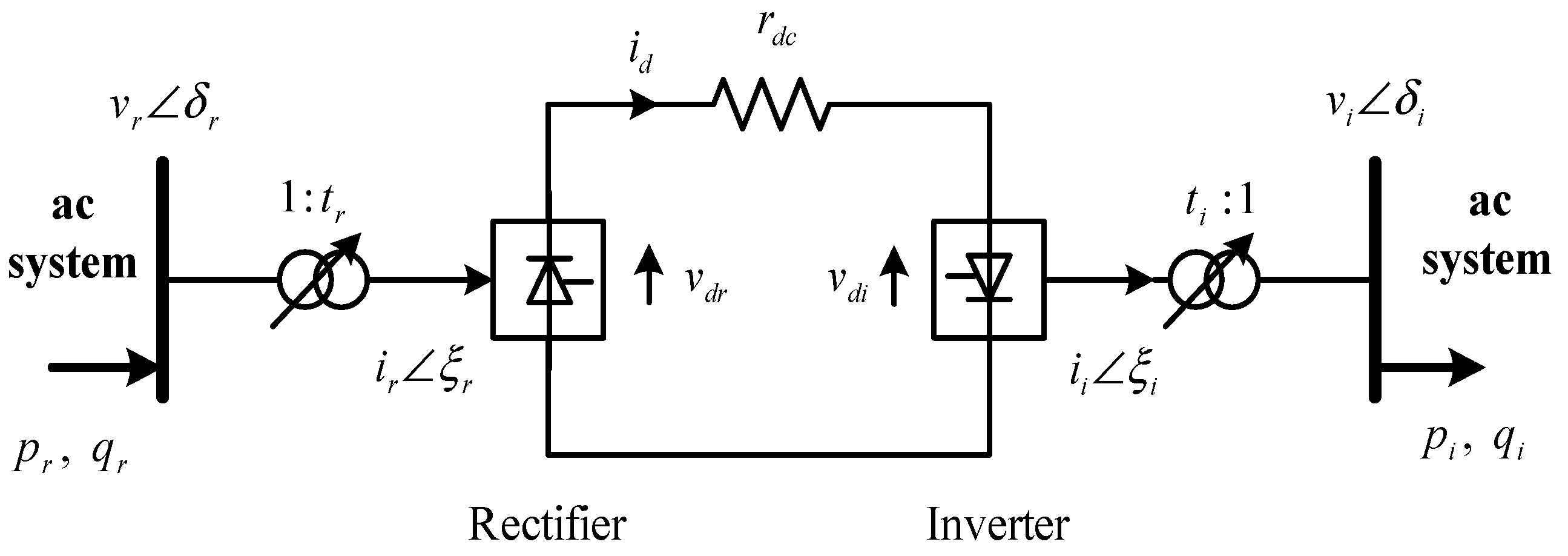
Figure 1. A two-terminal HVDC transmission line scheme [36].
Energies 17 00749 g001
Figure 2. An equivalent circuit of HVDC line [36].
Energies 17 00749 g002
Figure 3. A simple flow chart of the BSA.
Energies 17 00749 g003
Figure 4. An illustration of the SCB locations for Case 2.
Energies 17 00749 g004
Figure 5. An illustration of the HVDC link and ideal SCB locations for Case 3.
Energies 17 00749 g005
Figure 6. Reactive power of rectifier and inverter sides.
Energies 17 00749 g006
Figure 7. The transformer tap ratios.
Energies 17 00749 g007
Figure 8. DC current in the HVDC link.
Energies 17 00749 g008
Figure 9. The voltage profile of the test system in all cases.
Energies 17 00749 g009
Figure 10. The fitness value for Cases 2 and 3.
Energies 17 00749 g010
Table 1. Algorithms and objective functions of the HVDC field.
Method Objective FunctionTest SystemYear
[20]Fitness-distance Balance-based Stochastic Fractal Search (SFS), (FDB-SFS)Power Loss Voltage Deviation, CostIEEE 30 bus system2023
[21]ETAPVoltage Profile36 bus (real system)2022
[22]Genetic Algorithm Power LossIEEE 14 and 30-bus system
The modified New England 39
2014
[23]Differential evolution algorithmCostIEEE 5, 9, 118-bus
The modified New England 39
2018
[24]Differential evolution with neighborhood mutation (DENM)Power LossThe modified New England 39,
114 bus (real system)
2018
[25]Power Flow (PF) algorithmPower LossIEEE 5 bus and Modified England IEEE 39 bus system2019
[26]Artificia Bee Colony (ABC)Power Loss Voltage Deviation CostIEEE 30 bus system2016
[27]Harmonic Power FlowHarmonicIEEE 30 bus system2022
[28]Fast Differential Equation Power Flow (DEPF)relative speed of computations (RSC)IEEE 39, 118, 145, 300-bus system, 1153 bus (real system), and 4438 bus(real system)2023
[29]Semidefinite programming (SDP)Power LossModified CIGRE, IEEE 33 bus system2022
[30]OPF modelCostIEEE 39 bus system2022
[31]BSAPower LossIEEE 30 bus system2021
[32]Teaching Learning-based Optimization (TLBO)CostIEEE14, 30 and 572021
Table 2. Method 1 and Method 2 produced comparable results for Case 1 and 2.
Control VariablesLimitMethod 1
(Case 2)
Method 2
(Case 2)
Default
(Case 1)
LowHigh
pg103.6021.227451.271882.57549
pg201.41.400001.362500.51450
qg1−11−0.110260.03135−0.18687
qg2−0.40.50.278300.085942.17192
qc5−0.40.40.4000000.366644--
qc8−0.10.40.4000000.400000--
qc11−0.060.240.2400000.194316--
qc13−0.060.240.0900000.240000--
v111.151.0781.0711.000
v211.151.0731.0581.000
v511.151.0461.0290.875
v811.151.0381.0270.857
v1111.151.0891.0780.877
v1311.151.0221.0540.872
t(6–9)0.91.10.98960.98780.9500
t(6–10)0.91.10.97160.93150.9500
t(4–12)0.91.11.01801.02360.9500
t(28–27)0.91.10.97530.98640.9500
CB1(MVAR)01010.0(5)9.5(5)--
CB2(MVAR)01010.0(24)10.0(30)--
CB3(MVAR)01010.0(30)10.0(19)--
Power loss(p.u)9.34509.537325.599
Table 3. Method 1 and Method 2 produced comparable results for Case 3.
Control VariablesLimitMethod 1Method 2
LowHigh
pg103.6021.238171.29303
pg201.41.400001.37267
qg1−11−0.021480.09383
qg2−0.40.50.250300.33611
qc5−0.40.40.400.39
qc8−0.10.40.400.40
qc11−0.060.240.240.13
qc13−0.060.240.230.24
v111.151.0661.079
v211.151.0551.064
v511.151.0281.036
v811.151.0271.030
v1111.151.0831.070
v1311.151.0361.081
t(6–9)0.91.10.970.99
t(6–10)0.91.11.000.90
t(4–12)0.91.11.020.96
t(28–27)0.91.11.010.98
CB1(MVAR)01010.0 (7)8.75(5)
CB2(MVAR)01010.0 (23)8.50(30)
CB3(MVAR)0109.0(30)9.50(21)
Ploss(p.u)9.16079.272
Table 4. Control variable of DC system given by Methods 1 and 2 for Case 3.
Control Variablespdrpdiqdrqditrtialfa(o)thetavdrvdiid
Minimum limit 0.10.10.050.050.90.99.748.59110.1
Maximum limit 1.51.50.750.751.11.126301.51.51
Method 10.22710.22460.11360.11230.961.0125.653926.13741.22781.21390.1850
Method 20.34000.33360.17000.16680.900.9025.833325.25931.15641.13430.2941
Table 5. The line loss of the test system in all cases.
LineCase1Case2Case3
1–26.15300.69800.8340
1–33.76301.34701.1520
2–42.43901.06700.7420
2–54.52402.40802.4550
2–64.02501.77001.3600
3–41.04400.36100.3070
4–60.87800.35500.3650
4–12000
5–70.22400.14600.2850
6–70.49200.28200.2990
6–80.25400.09900.1000
6–9000
6–10000
2–280.12000.02700.0220
8–280.00400.00700.0060
9–11000
9–10000
10–200.12800.11900.0710
10–170.02300.03900.0220
10–210.16100.08400.1070
10–220.07500.03600.0490
12–13000
12–140.10700.05400.1220
12–150.30300.11500.1040
12–160.07100.02100.0800
14–150.008000.2660
15–180.05400.02700.0930
15–230.03900.00200.0020
16–170.00900.00300.0180
18–190.00600.00300.0260
19–200.02700.02800.0160
20–220.00100.00500.0030
22–240.05500.03400.0620
23–240.00600.01700.0660
24–250.03500.04000.0060
25–260.06600.04500.0480
25–270.09600.08400.0380
27–28000
27–290.12400.01200.0180
27–300.23400.00900.0150
29–300.04800.00100.0010
Disclaimer/Publisher’s Note: The statements, opinions and data contained in all publications are solely those of the individual author(s) and contributor(s) and not of MDPI and/or the editor(s). MDPI and/or the editor(s) disclaim responsibility for any injury to people or property resulting from any ideas, methods, instructions or products referred to in the content.