
Numerical Simulation of the Heat Transfer Inside a Shell and Tube Heat Exchanger Considering Different Variations in the Geometric Parameters of the Design


 ,
,  and
and
Abstract
1. Introduction
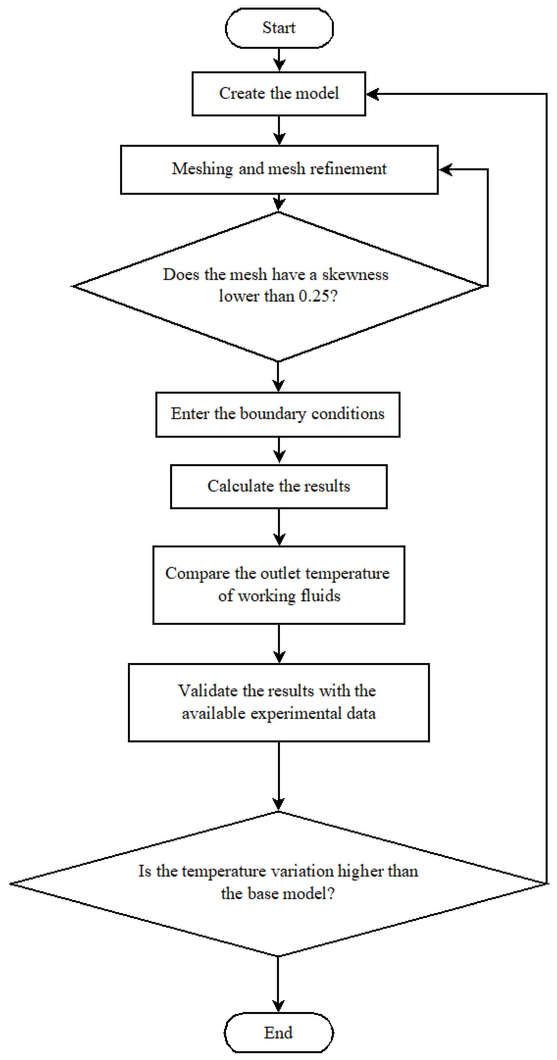
2. Materials and Methods
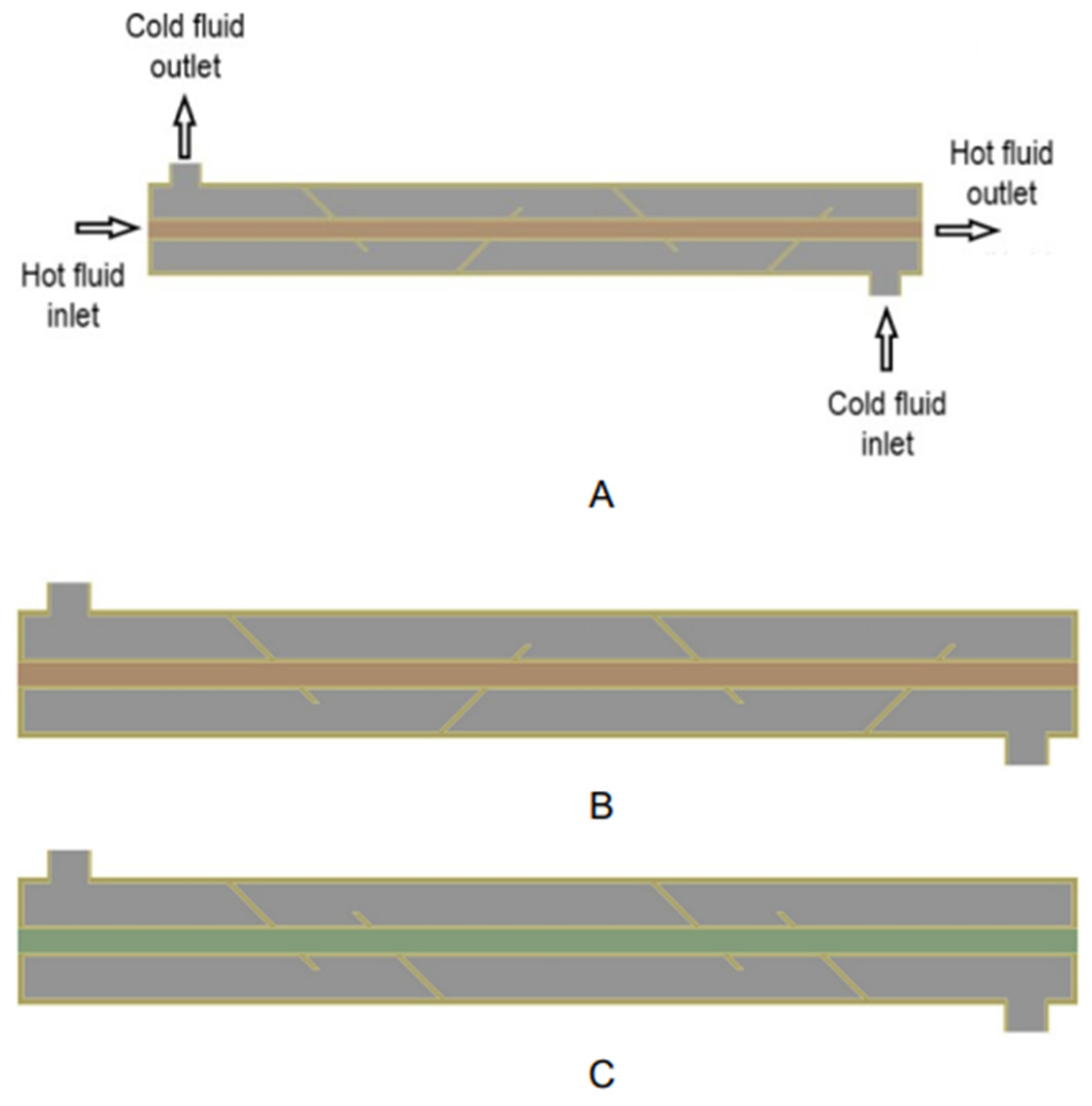
2.1. Parameters for Analysis
2.2. CFD Analysis
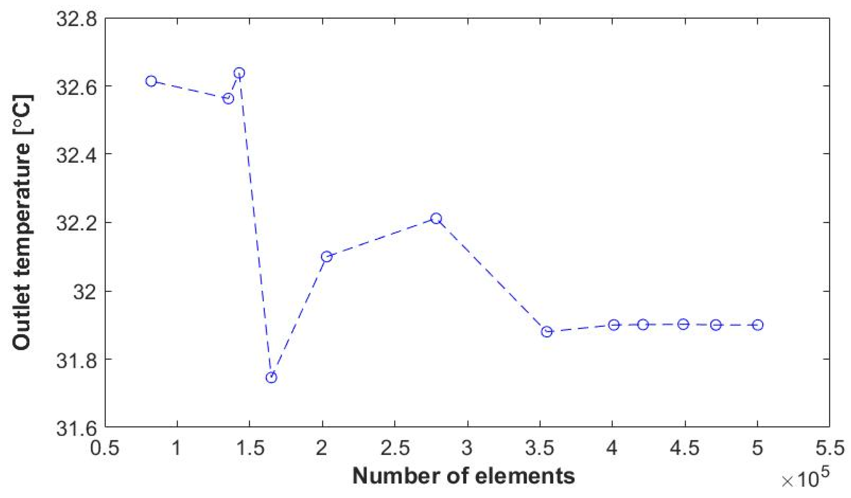
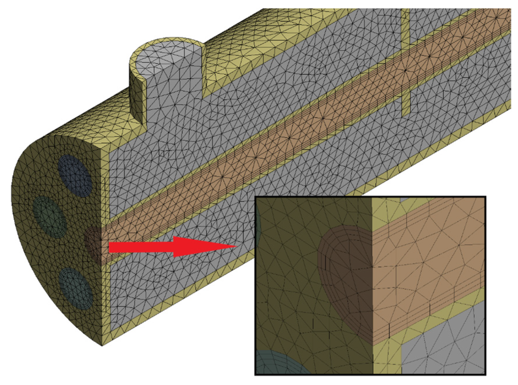
2.3. Meshing
2.4. Governing Equations
3. Results
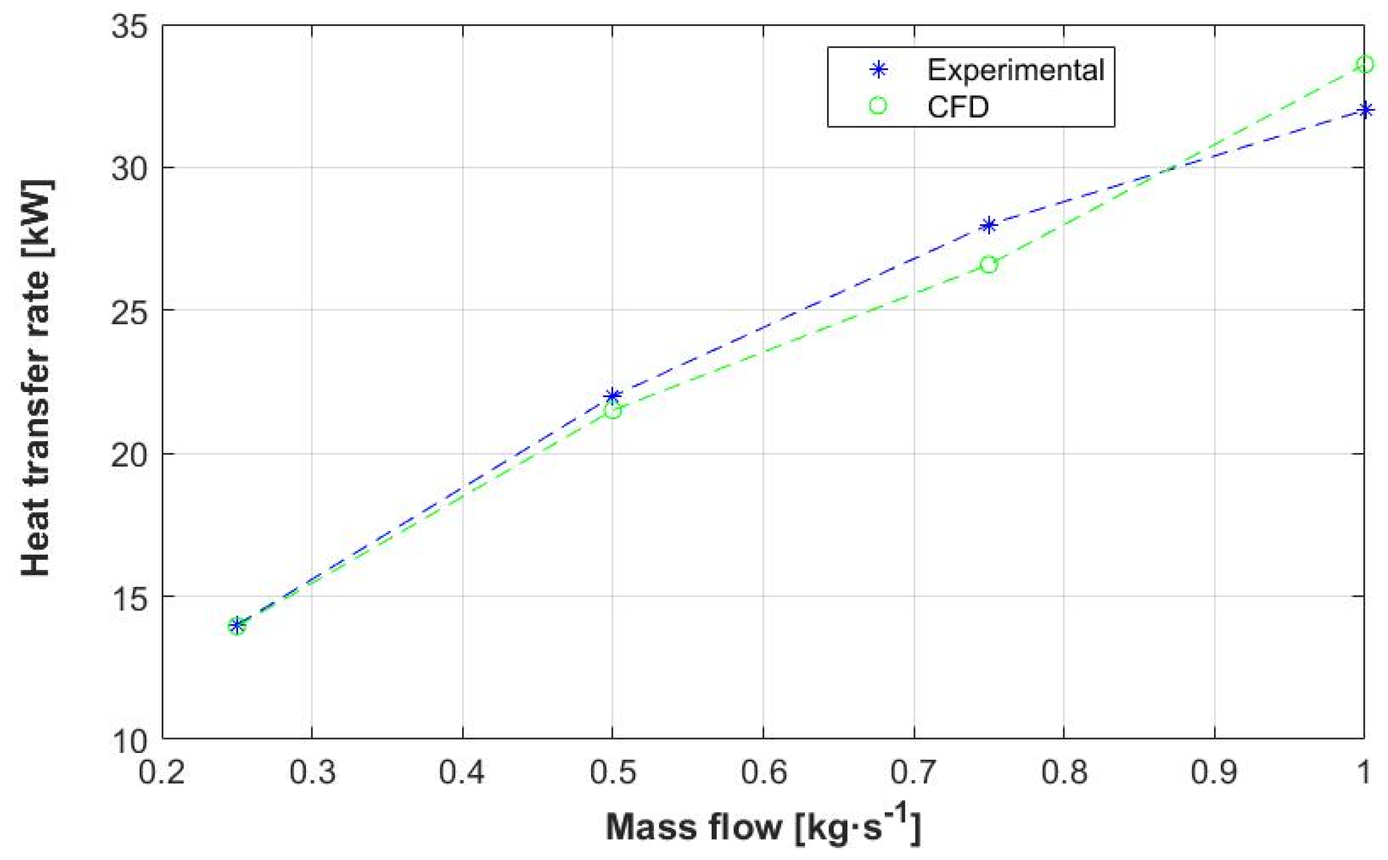
3.1. Validation
3.2. Base Model
3.3. Changes in Inclination
3.3.1. Inclination of 30°
3.3.2. Inclination of 45°
3.3.3. Inclination of 60°
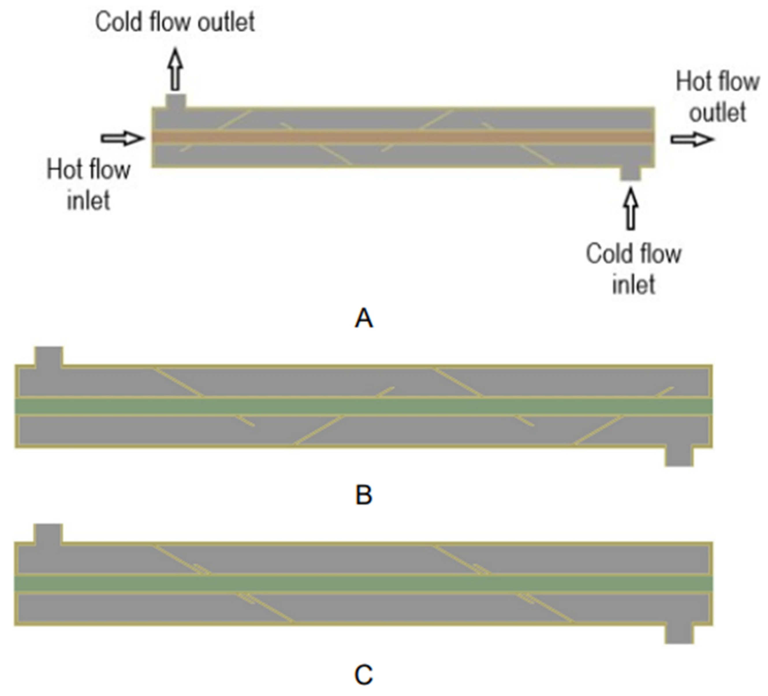
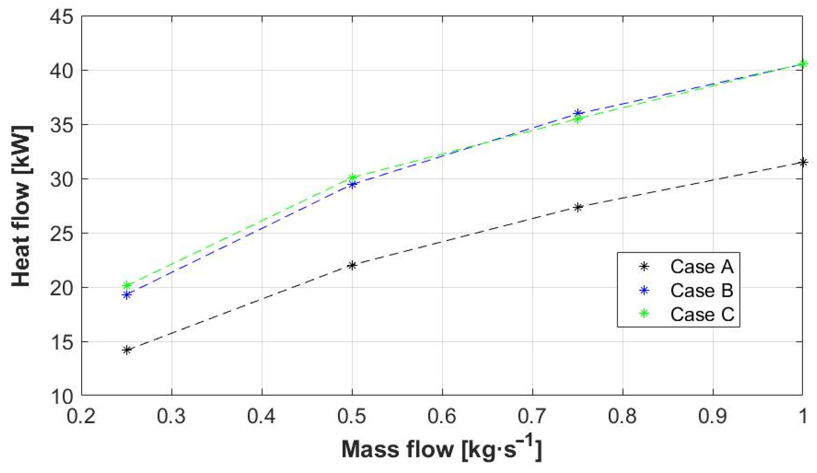
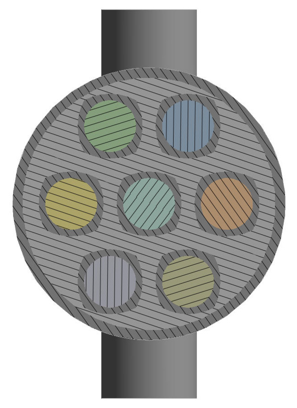
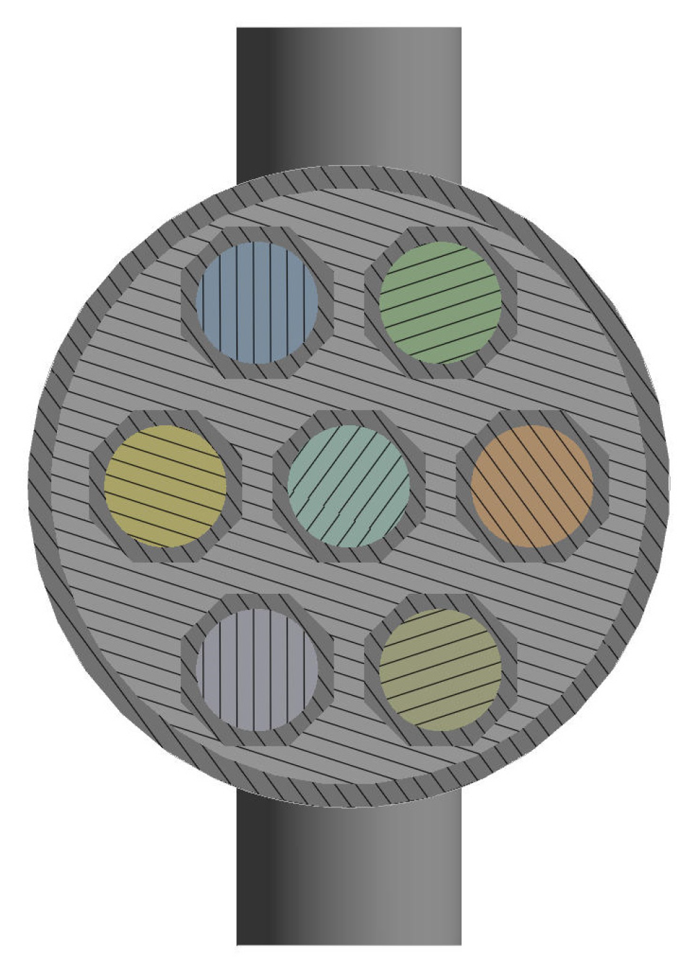
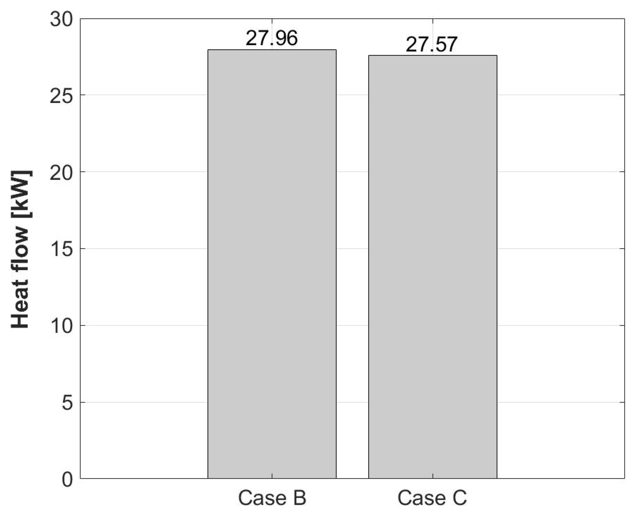
3.4. Changes in the Profile
3.4.1. Ellipse Profiles
3.4.2. Profiles with Arches
3.4.3. Octagonal Profiles
4. Discussion
5. Conclusions
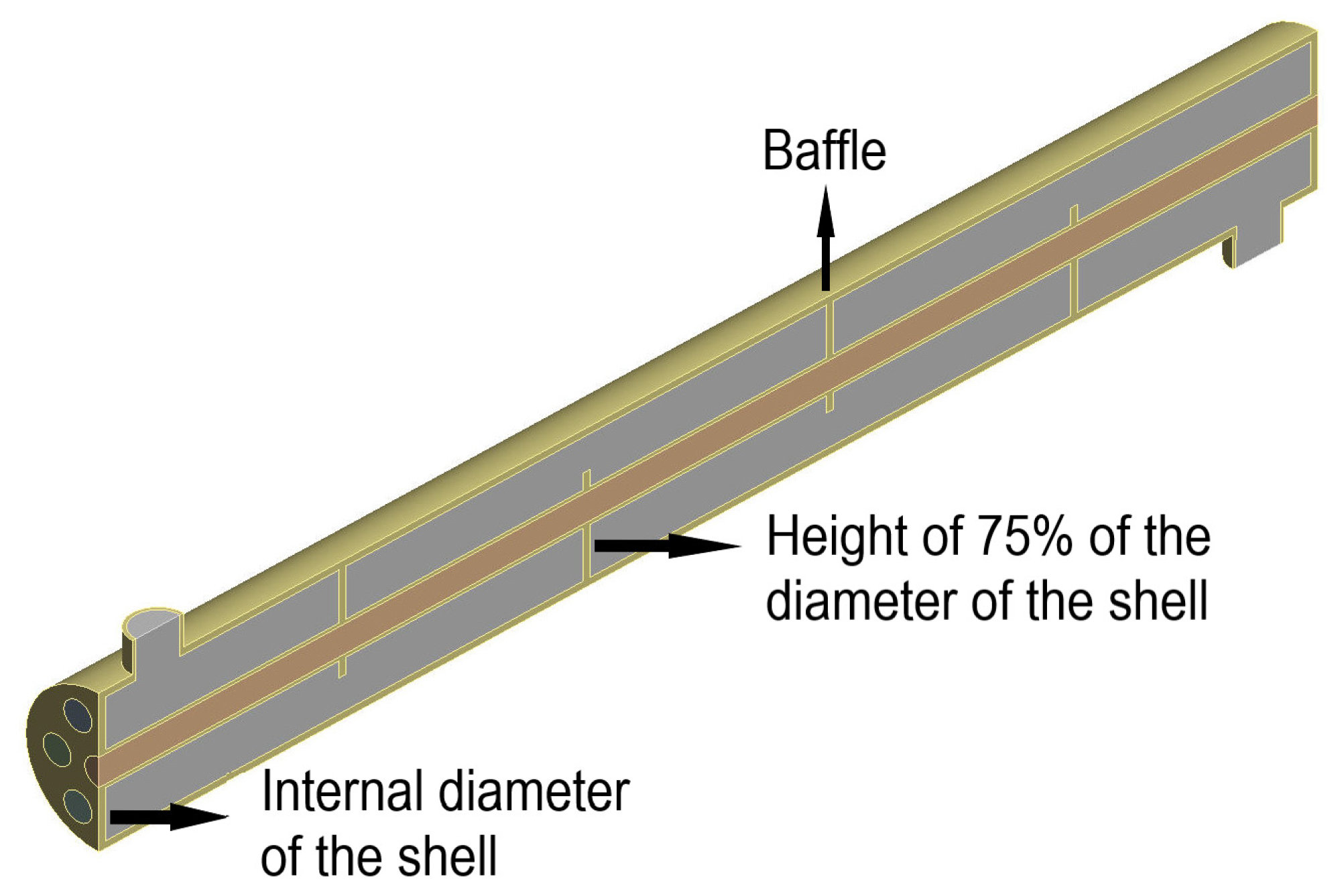
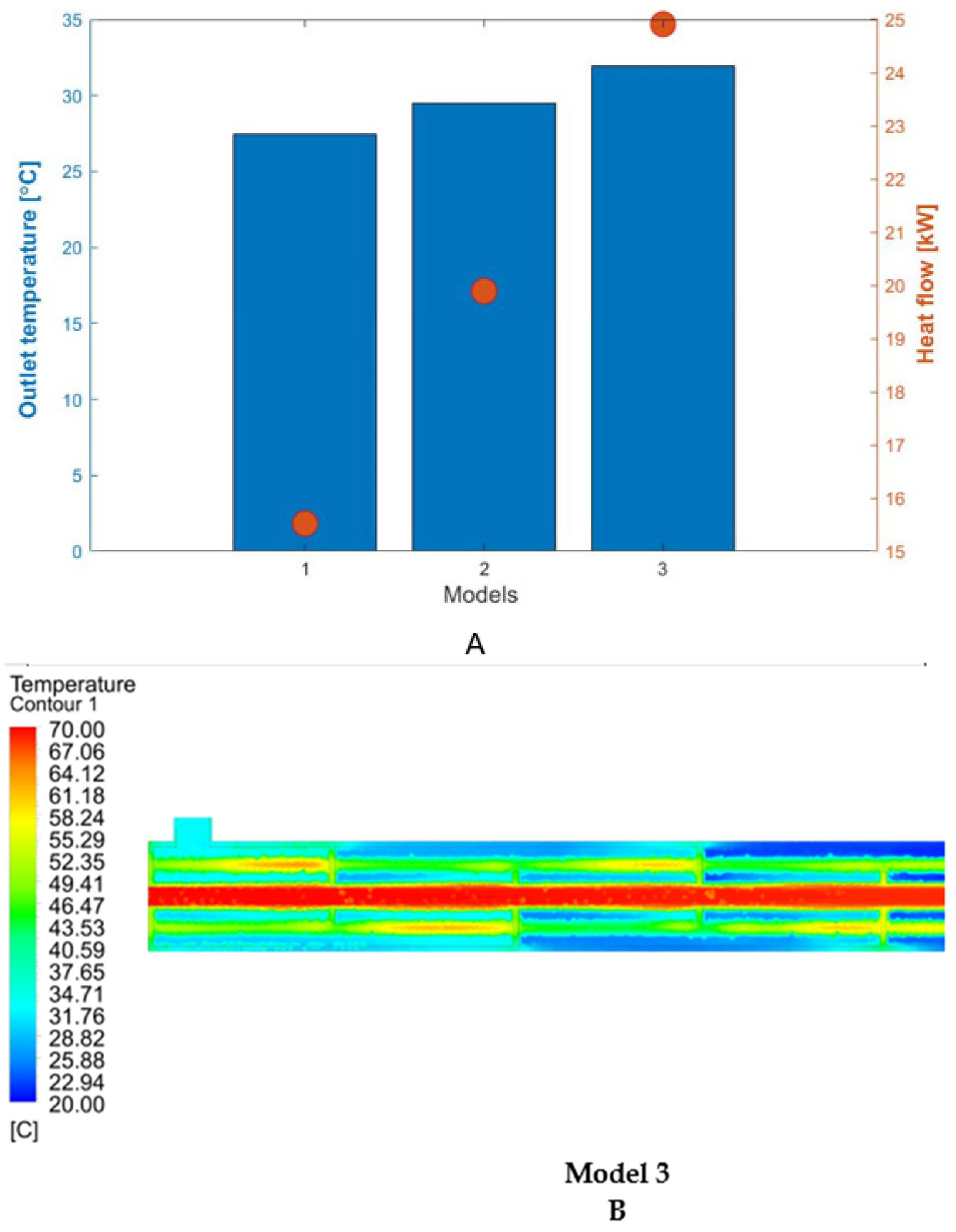
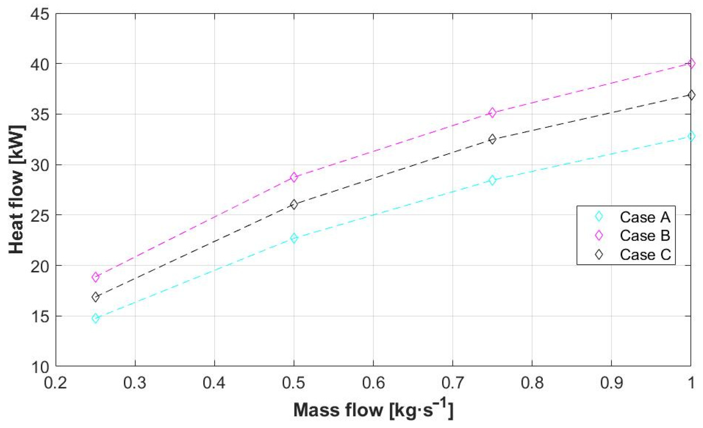
- The influence of the increase in the height of the baffle walls concerning the internal diameter of the shell was shown with the heat exchange in the device where average cold fluid outlet temperatures of 27.42, 29.51, and 31.91 °C were obtained for baffles with 25, 50, and 75% of the height, respectively.
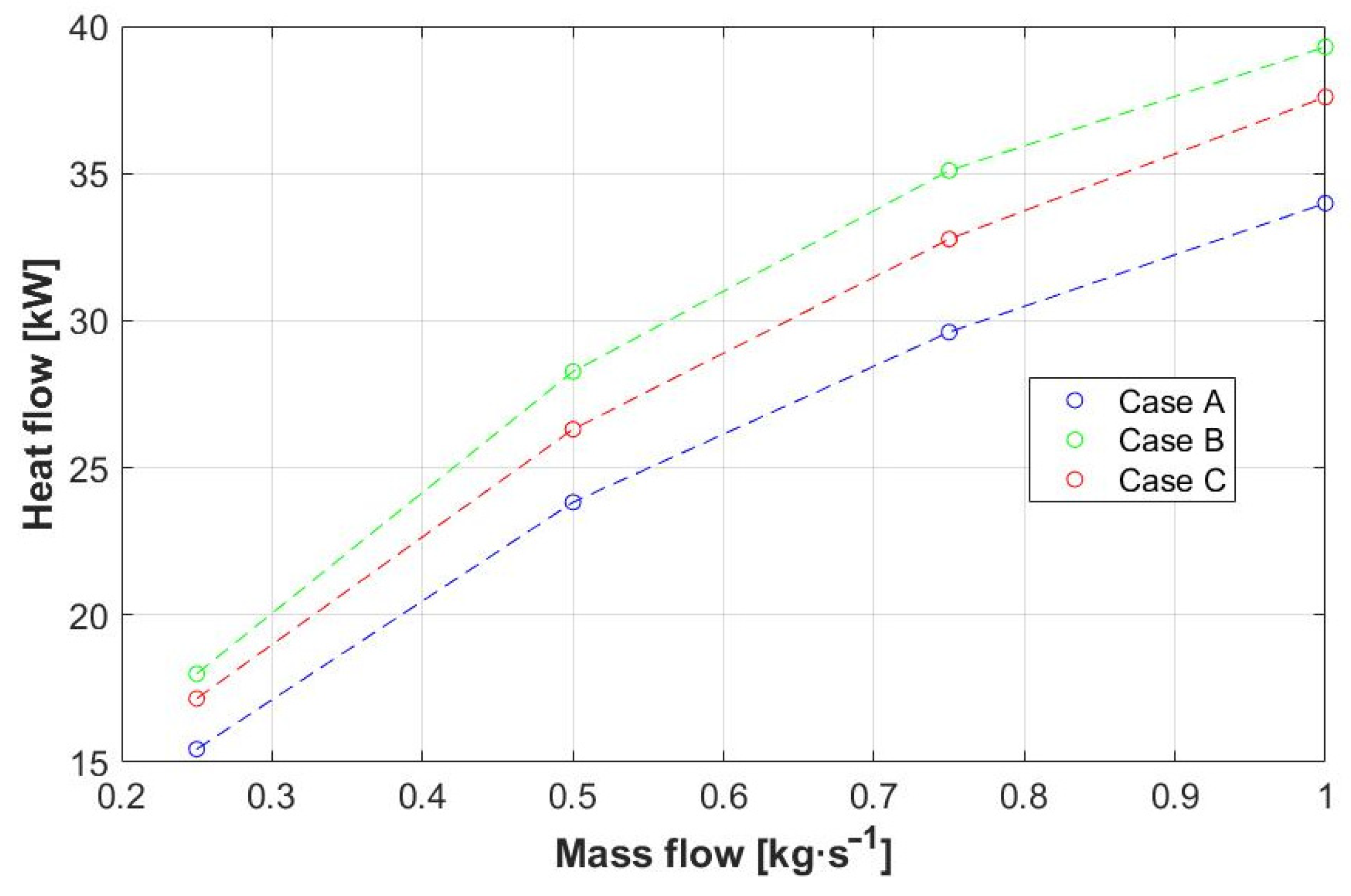
- The inclination of the deflector walls that generated the greatest temperature difference in the device was 60° for the horizontal axis, with heat fluxes of 29.44 and 30.07 kW for the ends oriented towards the cold fluid outlet and alternating, respectively. This demonstrates the positive influence of the baffles’ inclination in a higher heat transfer process.
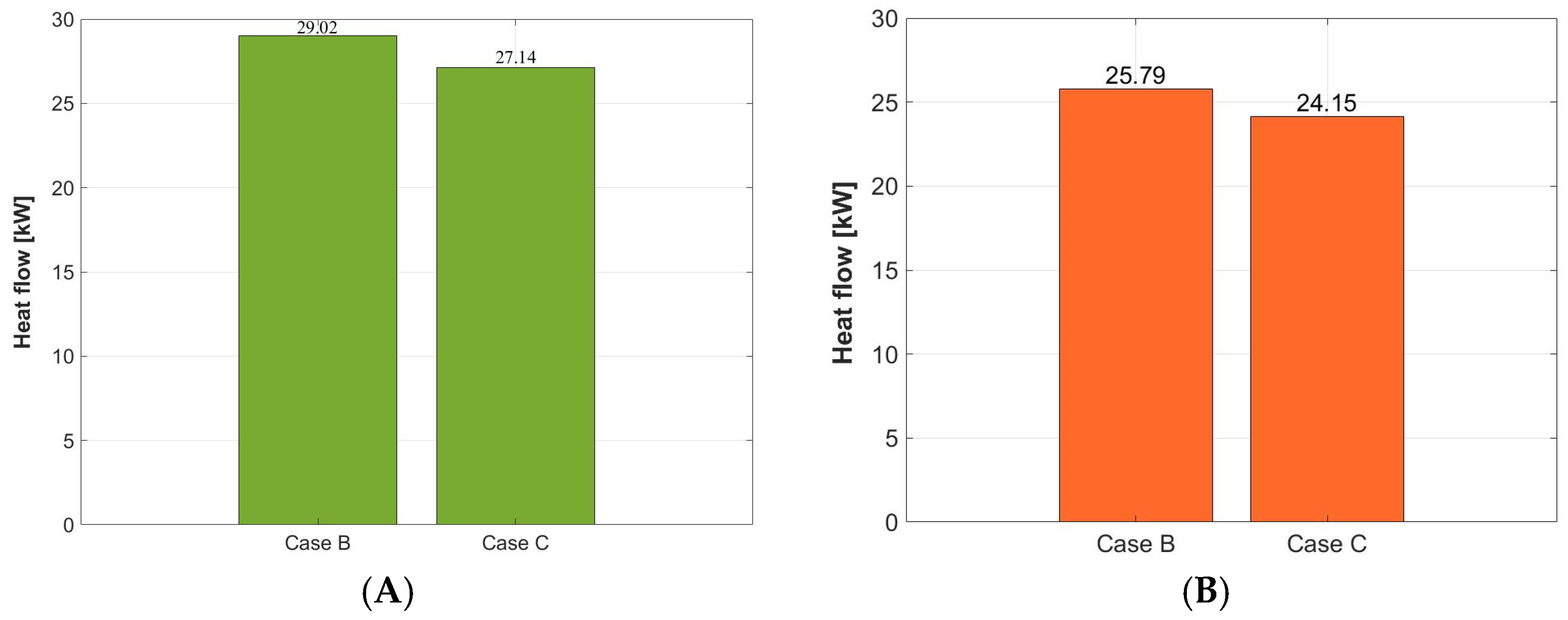
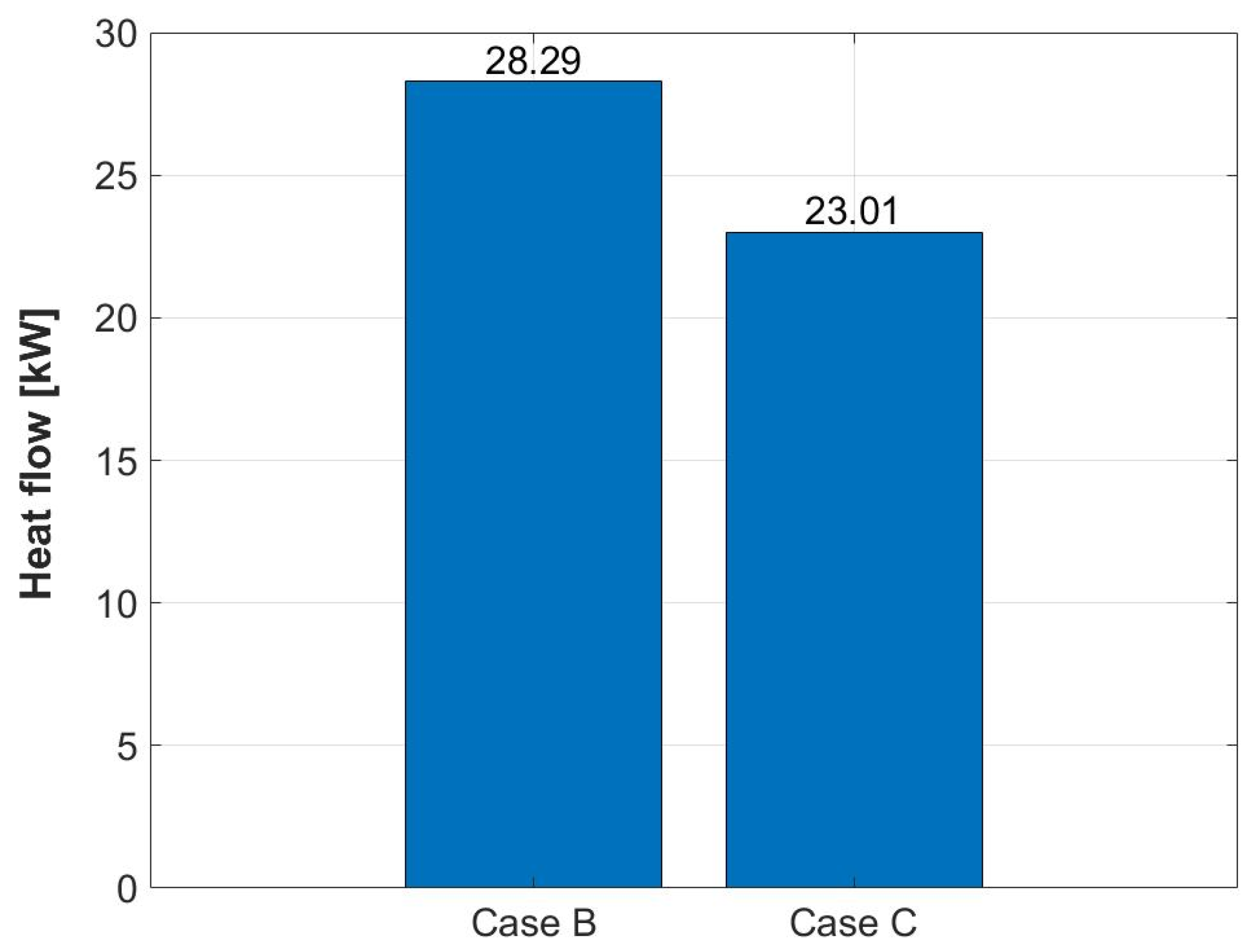
- The heat flux in a heat exchanger is directly proportional to the energy efficiency, considering that the lowest heat flux (24.15 kW) was generated by the combination of profiles with an elliptical shape vertically oriented and baffle walls with an inclination of 60°. This means that the combination cannot be recommended.
- The duct’s geometric shape that generated the greatest temperature difference between the inlets and outlets of the device, expressed by an increase in heat flow (29.02 kW), was the one that incorporated baffle walls with an inclination of 60° with the ends oriented toward the cold fluid outlet with a horizontal elliptical profile on the inner tubes.
- Comparing the highest heat fluxes obtained by the changes in the baffles’ inclination (29.44–30.07 kW) with the best heat flux presented in the combination of baffle inclination and different duct shape (29.02 kW), the baffle inclination emerges as the strongest geometric factor in the energy efficiency of the heat exchanger.
Author Contributions
Funding
Data Availability Statement
Acknowledgments
Conflicts of Interest
Nomenclature
| Symbol | Description |
| ρ | Density; [kg·m−3] |
| t | Time; [s] |
| V | Velocity; [m·s−1] |
| Sm | Mass source; [kg·m−3·s−1] |
| P | Pressure; [Pa] |
| μ | Dynamic viscosity; [Pa·s] |
| F | Force; [N] |
| E | Total energy; [J] |
| Grad operator | |
| Sh | Defined energy source; [W·m−3] |
| J | Mass flow; diffusion flow; [kg·m−2·s−1] |
| k | Kynetic energy turbulence; [m2·s−2] |
| u | Velocity magnitude; [m·s−1] |
| x | Axial coordinate |
| μt | Dynamic turbulence viscosity; [kg·m−1·s−1] |
| σk | Prandtl turbulence number |
| Gk | Kinetic turbulence energy generation |
| Gb | Flotability kinetic turbulence energy generation |
| Ɛ | Disipation rate; [m2·s−3] |
| Sk | Kinetic turbulence source; [kg·m−1·s−3] |
References
- Gupta, S.K.; Verma, H.; Yadav, N. A review on recent development of nanofluid utilization in shell & tube heat exchanger for saving of energy. Mater. Today Proc. 2021, 54, 579–589. [Google Scholar] [CrossRef]
- Mediaceja, Y.R.; Alfonso, H.L.L.; Sánchez-Escalona, A.A.; Camaraza-Medina, Y.; Corrales, M.F.S.; Urgelles, M.L.; Leyva, E.G. Análisis termoenergético del sistema de generación de vapor de una central térmica de 49 MW. Enfoque UTE 2020, 11, 87–101. [Google Scholar] [CrossRef]
- Lara-Montaño, O.D.; Gómez-Castro, F.I.; Gutiérrez-Antonio, C. Comparison of the performance of different metaheuristic methods for the optimization of shell-and-tube heat exchangers. Comput. Chem. Eng. 2021, 152, 107403. [Google Scholar] [CrossRef]
- Ünverdi, M. Prediction of heat transfer coefficient and friction factor of mini channel shell and tube heat exchanger using numerical analysis and experimental validation. Int. J. Therm. Sci. 2022, 171, 107182. [Google Scholar] [CrossRef]
- Ravikumar, M.; Raj, Y.A. Investigation of fin profile on the performance of the shell and tube heat exchanger. Mater. Today Proc. 2021, 45, 7910–7916. [Google Scholar] [CrossRef]
- Pereira, I.P.; Bagajewicz, M.J.; Costa, A.L. Global optimization of the design of horizontal shell and tube condensers. Chem. Eng. Sci. 2021, 236, 116474. [Google Scholar] [CrossRef]
- Yang, Z.; Ma, Y.; Zhang, N.; Smith, R. Optimization of Shell and Tube Heat Exchangers Sizing with Heat Transfer Enhancement. Comput. Aided Chem. Eng. 2020, 48, 937–942. [Google Scholar] [CrossRef]
- Li, X.; Wang, L.; Feng, R.; Wang, Z.; Liu, S.; Zhu, D. Study on shell side heat transport enhancement of double tube heat exchangers by twisted oval tubes. Int. Commun. Heat Mass Transf. 2021, 124, 105273. [Google Scholar] [CrossRef]
- Bahiraei, M.; Naseri, M.; Monavari, A. A CFD study on thermohydraulic characteristics of a nanofluid in a shell-and-tube heat exchanger fitted with new unilateral ladder type helical baffles. Int. Commun. Heat Mass Transf. 2021, 124, 105248. [Google Scholar] [CrossRef]
- Arani, A.A.A.; Uosofvand, H. Double-pass shell-and-tube heat exchanger performance enhancement with new combined baffle and elliptical tube bundle arrangement. Int. J. Therm. Sci. 2021, 167, 106999. [Google Scholar] [CrossRef]
- Ren, H.; He, M.; Lin, W.; Yang, L.; Li, W.; Ma, Z. Performance investigation and sensitivity analysis of shell-and-tube phase change material thermal energy storage. J. Energy Storage 2020, 33, 102040. [Google Scholar] [CrossRef]
- Quitiaquez, W.; Estupinan-Campos, J.; Isaza-Roldan, C.A.; Nieto-Londono, C.; Quitiaquez, P.; Toapanta-Ramos, F. Numerical simulation of a collector/evaporator for direct-expansion solar-assisted heat pump. In Proceedings of the 2020 IEEE ANDESCON, Quito, Ecuador, 13–16 October 2020; pp. 1–6. [Google Scholar]
- Li, N.; Chen, J.; Cheng, T.; Klemeš, J.J.; Varbanov, P.S.; Wang, Q.; Yang, W.; Liu, X.; Zeng, M. Analysing thermal-hydraulic performance and energy efficiency of shell-and-tube heat exchangers with longitudinal flow based on experiment and numerical simulation. Energy 2020, 202, 117757. [Google Scholar] [CrossRef]
- El-Said, E.M.; Elsheikh, A.H.; El-Tahan, H.R. Effect of curved segmental baffle on a shell and tube heat exchanger thermohydraulic performance: Numerical investigation. Int. J. Therm. Sci. 2021, 165, 106922. [Google Scholar] [CrossRef]
- Biçer, N.; Engin, T.; Yaşar, H.; Büyükkaya, E.; Aydın, A.; Topuz, A. Design optimization of a shell-and-tube heat exchanger with novel three-zonal baffle by using CFD and taguchi method. Int. J. Therm. Sci. 2020, 155, 106417. [Google Scholar] [CrossRef]
- Elmekawy, A.M.N.; Ibrahim, A.A.; Shahin, A.M.; Al-Ali, S.; Hassan, G.E. Performance enhancement for tube bank staggered configuration heat exchanger—CFD Study. Chem. Eng. Process. Process Intensif. 2021, 164, 108392. [Google Scholar] [CrossRef]
- Vivekanandan, M.; Saravanan, G.; Vijayan, V.; Gopalakrishnan, K.; Krishna, J.P. Experimental and CFD investigation of spiral tube heat exchanger. Mater. Today Proc. 2020, 37, 3689–3696. [Google Scholar] [CrossRef]
- Kola, P.V.K.V.; Pisipaty, S.K.; Mendu, S.S.; Ghosh, R. Optimization of performance parameters of a double pipe heat exchanger with cut twisted tapes using CFD and RSM. Chem. Eng. Process. Process Intensif. 2021, 163, 108362. [Google Scholar] [CrossRef]
- Aliaga, D.; Feick, R.; Brooks, W.; Mery, M.; Gers, R.; Levi, J.; Romero, C. Modified solar chimney configuration with a heat exchanger: Experiment and CFD simulation. Therm. Sci. Eng. Prog. 2021, 22, 100850. [Google Scholar] [CrossRef]
- Vivekanandan, M.; Venkatesh, R.; Periyasamy, R.; Mohankumar, S.; Devakumar, L. Experimental and CFD investigation of helical coil heat exchanger with flower baffle. Mater. Today Proc. 2020, 37, 2174–2182. [Google Scholar] [CrossRef]
- Wen, T.; Lu, L.; He, W.; Min, Y. Fundamentals and applications of CFD technology on analyzing falling film heat and mass exchangers: A comprehensive review. Appl. Energy 2020, 261, 114473. [Google Scholar] [CrossRef]
- Quitiaquez, W.; Estupiñán-Campos, J.; Nieto-Londoño, C.; Quitiaquez, P. CFD Analysis of Heat Transfer Enhancement in a Flat-Plate Solar Collector/Evaporator with Different Geometric Variations in the Cross Section. Energies 2023, 16, 5755. [Google Scholar] [CrossRef]
- Chihab, Y.; Garoum, M.; Laaroussi, N. Dynamic thermal performance of multilayer hollow clay walls filled with insulation materials: Toward energy saving in hot climates. Energy Built Environ. 2024, 5, 70–80. [Google Scholar] [CrossRef]
- Wang, Z.; Suen, K. Numerical comparisons of the thermal behaviour of air and refrigerants in the vortex tube. Appl. Therm. Eng. 2020, 164, 114515. [Google Scholar] [CrossRef]
- Jiang, H.; Niu, F.; Ma, Q.; Su, W.; Wang, E.; He, J. Numerical analysis of heat transfer between air inside and outside the tunnel caused by piston action. Int. J. Therm. Sci. 2021, 170, 107164. [Google Scholar] [CrossRef]
- Elgendy, H.; Czerski, K. Numerical Study of Flow and Heat Transfer Characteristics in a Simplified Dual Fluid Reactor. Energies 2023, 16, 4989. [Google Scholar] [CrossRef]
- Arsenyeva, O.; Tovazhnyanskyy, L.; Kapustenko, P.; Klemeš, J.J.; Varbanov, P.S. Review of Developments in Plate Heat Exchanger Heat Transfer Enhancement for Single-Phase Applications in Process Industries. Energies 2023, 16, 4976. [Google Scholar] [CrossRef]
- Olabi, A.; Wilberforce, T.; Sayed, E.T.; Elsaid, K.; Rahman, S.A.; Abdelkareem, M.A. Geometrical effect coupled with nanofluid on heat transfer enhancement in heat exchangers. Int. J. Thermofluids 2021, 10, 100072. [Google Scholar] [CrossRef]
- Hadibafekr, S.; Mirzaee, I.; Khalilian, M.; Shirvani, H. Thermohydraulic performance intensification of lobed heat exchangers using tube axis corrugation: Numerical assessment on geometrical configurations. Chem. Eng. Process. Process Intensif. 2022, 171, 108763. [Google Scholar] [CrossRef]
- Cando, A.X.A.; Sarzosa, W.Q.; Toapanta, L.F. CFD Analysis of a solar flat plate collector with different cross sections. Enfoque UTE 2020, 11, 95–108. [Google Scholar] [CrossRef]
- Quitiaquez, P.; Cocha, J.; Quitiaquez, W.; Vaca, X. Investigation of geometric parameters with HSS tools in machining polyamide 6 using Taguchi method. Mater. Today Proc. 2022, 49, 181–187. [Google Scholar] [CrossRef]


| Input Parameters | ||
|---|---|---|
| Mass Flow Rate [kg·s−1] | Temperature Inlet [°C] | |
| Cold fluid | 0.25, 0.5, 0.75, 1 | 20 |
| Hot fluid | 0.3 | 70 |
| Water | ||||
|---|---|---|---|---|
| Temperature [°C] | Density [kg·m−3] | Thermal Conductivity [W·m−1·K−1] | Specific Heat Capacity [J·kg−1·K−1] | Dynamic Viscosity [kg·m−1·s−1] |
| 20 | 998.2 | 0.5861 | 4183 | 0.001002 |
| 30 | 995.7 | 0.603 | 4183 | 0.0007977 |
| 40 | 992.2 | 0.6178 | 4182 | 0.0006533 |
| 50 | 988 | 0.6305 | 4181 | 0.0005471 |
| 60 | 983.2 | 0.641 | 4183 | 0.0004666 |
| 70 | 977.8 | 0.6495 | 4187 | 0.0004041 |
| Copper | ||||
| Density [kg·m−3] | Thermal Conductivity [W·m−1·K−1] | Specific Heat Capacity [J·kg−1·K−1] | ||
| 8978 | 387.6 | 381 | ||
| Model | Number of Elements Average | Skewness Average |
|---|---|---|
| Exchanger for validation | 3,509,554 | 0.2899 |
| Initial model 1 (baffles with 25% of the height) | 467,003 | 0.238 |
| Initial model 2 (baffles with 50% of the height) | 471,875 | 0.2405 |
| Starting model 3 (baffles with 75% of the height) | 448,733 | 0.2417 |
| Models with inclined baffle (30°) | 471,552 | 0.2404 |
| Models with inclined baffle (45°) | 479,986 | 0.2406 |
| Models with inclined baffle (60°) | 500,137 | 0.2422 |
| Inner tube models with arches and inclined baffles (60°) | 483,386 | 0.2413 |
| Elliptical (vertical) inner tube models with inclined baffles (60°) | 497,216 | 0.2735 |
| Elliptical (horizontal) inner tube models with inclined baffles (60°) | 492,203 | 0.2767 |
| Octagonal inner tube models with inclined baffles (60°) | 495,627 | 0.253 |
| Pressure–Velocity Coupling | |
|---|---|
| Schematic | Coupling |
| Spatial Discretization | |
| Pressure | Second order |
| Momentum | Second order |
| Energy | Second order |
| Kinetic energy turbulence | Second order |
| Turbulence dissipation rate | Second order |
| Length [m] | Internal Diameter of the Pipes [m] | External Diameter of the Pipes [m] | Internal Diameter of the Shell [m] | External Diameter of the Shell [m] | Distance between Tubes [m] | Internal Diameter of External Pipe [m] | Distance between Baffles [m] |
|---|---|---|---|---|---|---|---|
| 0.35 | 0.008 | 0.010 | 0.038 | 0.042 | 0.012 | 0.012 | 0.07 |
Disclaimer/Publisher’s Note: The statements, opinions and data contained in all publications are solely those of the individual author(s) and contributor(s) and not of MDPI and/or the editor(s). MDPI and/or the editor(s) disclaim responsibility for any injury to people or property resulting from any ideas, methods, instructions or products referred to in the content. |
© 2024 by the authors. Licensee MDPI, Basel, Switzerland. This article is an open access article distributed under the terms and conditions of the Creative Commons Attribution (CC BY) license (https://creativecommons.org/licenses/by/4.0/).
Share and Cite
Estupiñán-Campos, J.; Quitiaquez, W.; Nieto-Londoño, C.; Quitiaquez, P. Numerical Simulation of the Heat Transfer Inside a Shell and Tube Heat Exchanger Considering Different Variations in the Geometric Parameters of the Design. Energies 2024, 17, 691. https://doi.org/10.3390/en17030691
Estupiñán-Campos J, Quitiaquez W, Nieto-Londoño C, Quitiaquez P. Numerical Simulation of the Heat Transfer Inside a Shell and Tube Heat Exchanger Considering Different Variations in the Geometric Parameters of the Design. Energies. 2024; 17(3):691. https://doi.org/10.3390/en17030691
Chicago/Turabian StyleEstupiñán-Campos, José, William Quitiaquez, César Nieto-Londoño, and Patricio Quitiaquez. 2024. "Numerical Simulation of the Heat Transfer Inside a Shell and Tube Heat Exchanger Considering Different Variations in the Geometric Parameters of the Design" Energies 17, no. 3: 691. https://doi.org/10.3390/en17030691
APA StyleEstupiñán-Campos, J., Quitiaquez, W., Nieto-Londoño, C., & Quitiaquez, P. (2024). Numerical Simulation of the Heat Transfer Inside a Shell and Tube Heat Exchanger Considering Different Variations in the Geometric Parameters of the Design. Energies, 17(3), 691. https://doi.org/10.3390/en17030691