Article

Evaluation Method and Analysis on Performance of Diffuser in Heat Storage Tank

1
Department of Energy and Power Engineering, Northeast Electric Power University, Jilin 132013, China
2
State Grid Jilin Electric Power Research Institute, Changchun 130021, China
*
Author to whom correspondence should be addressed.
Energies 2024, 17(3), 618; https://doi.org/10.3390/en17030618
Submission received: 22 November 2023 / Revised: 12 January 2024 / Accepted: 24 January 2024 / Published: 27 January 2024
(This article belongs to the Section J: Thermal Management)

Abstract

:
The diffuser is a critical component in a heat storage tank, and its structure has an important influence on the thermal performance of the heat storage tank. At present, research on the structure of diffusers often focuses on the change of one single parameter, which results in the need for a comprehensive structure analysis of diffusers in heat storage tanks. This paper comprehensively considers the inlet diameter, hole distance, and hole diameter of the diffuser and the inlet conditions of the heat storage tank. Then, a new evaluation index, namely the non-uniformity coefficient of the diffuser, is proposed. The experiments verify the accuracy of numerical calculation, and the related empirical formula is summarized finally. The results show that the diffuser with a small non-uniformity coefficient can achieve thin temperature stratification and higher exergy efficiency. In other words, the non-uniformity coefficient is in good agreement with temperature stratification and the exergy efficiency of the heat storage tank. When the flow rate of the inlet device is 0.5 m/s, the exergy efficiency increases by nearly 30 percentage points and the non-uniformity coefficient of the No. 4 diffuser is 3.39%. In contrast, that of the No. 8 diffuser is 75.17%. This evaluation index is suitable for different diffuser types with high accuracy. It provides the theoretical and experimental basis for the structural design and selection of diffusers for heat storage tanks.

1. Introduction

The structures of inlet devices have an important influence on the thermal performance in heat storage tanks. The outlet flow of a well-performing diffuser will form a uniform liquid layer, which can reduce disturbance in the tank. Thin temperature stratification is helpful to improve the thermal performance of heat storage tanks [1]. The water distribution uniformity of a diffuser depends mainly on its structure [2]. Therefore, it is of great significance to study the influence of different factors on the water distribution performance of diffusers and to analyze and evaluate the thermal performance of heat storage tanks.
Changing the installation position, shape, and structure of the diffuser will have a significant impact on its performance [3,4,5]. Therefore, many scholars have studied the influencing factors of diffusers in different directions and optimized the design scheme. An optimal design of the octagonal water diffuser with uniform flow orifice plate is proposed by Tang et al. [6] Comparative analysis of the influence of two different shapes of water distributors on the performance of heat storage tanks is proved by Karim [7]. Weiss improved the temperature stratification by optimizeding inlet design for tank thermal energy storage systems with flat diffuser [8]. A new design type of diffuser is proposed in reference [9].
Different method have been applied to visually show the changes of fluid flowing through the diffuser. For example, a three-dimensional Computational Fluid Dynamics (CFD) method was used in references [10,11], and an experimental method was used in references [12,13]. A study on the influence of single factors such as water distributor diameter, hole number, and hole diameter on the distribution of temperature layer in heat storage tanks is reported in reference [14]. The temperature stratification analysis method is used to study the influence of different factors on the performance of the heat storage tanks [15]. The effects of the other two factors on the distribution of the temperature layer were proposed in different research. One is pipe diameter proposed in references [16,17], the other is, shape proposed in reference [18]. The guidelines of flow diffuser design and adapted operational conditions are reported by Lou et al. [19]. A new mathematical model established to analyze complex energy systems is introduced in reference [20]. In the above literature, the influence of one single variable has been proposed, but very few studies have proposed the theoretical correlation of multiple variables.
In this work, based on the principle of uniform flow of water distribution holes, the authors propose a new method to evaluate the thermal performance of diffusers in heat storage tanks. This method is a numerical calculation method. Based on the dimensional analysis of the index by the Buckingham theorem, the correlation empirical formula is obtained by data fitting. The feasibility and effectiveness of the new evaluation method are verified by experiments. It avoids the difficulty that only experimental measurement or CFD simulation can be used in the evaluation of a diffuser, which greatly reduces the cost of capital and saves the cost of time.

2. Determination Method of Non-Uniformity Coefficient

2.1. Putting Forward the Non-Uniformity Coefficient

The hot water flows out of the diffuser and mixes with the cold water after charging with cold water. Due to the density difference, temperature stratification will occur between the cold and hot water. If the flow rate of all holes in the diffuser is uniform, the temperature stratification will be thin and stable. The statistical standard deviation of the liquid flow rate at each diffuser hole can express the water distribution effect. Since the water distribution effect mainly characterizes the uniformity of the flow of each diffuser hole, we can use the non-uniformity coefficient η e as an evaluation index. Equation (1) shows the corresponding formula.
ξ = 1 n i = 1 n Q i Q ¯ Q ¯ 2 ,   Q ¯ = 1 n Q 1 + Q 2 + + Q n
According to the practical significance of the non-uniformity coefficient, the smaller the non-uniformity coefficient, the more uniform the flow rate of each diffuser hole and the more stable the uniform liquid film. The larger the non-uniformity coefficient, the more the non-uniformity flow rate in each hole of the diffuser leads to strong disturbance mixing and poor stratification effect.

2.2. Dimensional Analysis of Non-Uniformity Coefficient

The non-uniformity coefficient greatly influences the structural parameters of the diffuser and water flow parameters. The Buckingham theorem is applied to solve the expression of the non-uniformity coefficient in references [21,22,23]. This method have also been used in other different fields [24,25]. The inlet diameter, hole distance, and hole diameter of the diffuser are related to the structure. The inlet velocity, total inlet pressure, and dynamic viscosity are related to the inlet conditions.
The different inlet velocities lead to different inlet flow rates, the total inlet pressure determines the pressure distribution of each hole, and the turbulence degree in the diffuser is determined by Re, which is related to water dynamic viscosity. In summary, the main related parameters of the water distribution non-uniformity coefficient ξ are the total inlet pressure p, the water flow velocity u, the inlet diameter of diffuser D, the holes diameter d and the holes distance λ on the diffuser, and water dynamic viscosity μ. According to the Buckingham theorem, the related dimensionless number can be expressed as:
ξ = f ( p α , u β , D γ , λ ε , d θ , μ κ )
The basic dimensions selected for each parameter are: length dimension [L], time dimension [T], and mass dimension [M]. The above related parameters are dimensionless processed, so
[ ξ ] = [ L ] 0   [ M ] 0   [ T ] 0 [ p ] = [ L ]   [ M ]   [ T ] 2 [ u ] = [ M ]   [ T ] 1 [ D ] = [ L ] , [ λ ] = [ L ] , [ d ] = [ L ] , [ μ ] = [ L ] 1   [ M ]   [ T ] 1
According to the dimension equality on the left and right sides of Equation (2), it can obtain Equation (3).
L 0 M 0 T 0 = ( L M T 2 ) α ( M T 1 ) β ( L ) γ ( L ) ε ( L ) θ ( L 1 M T 1 ) κ
So,
L : α + β + γ + ε + θ κ = 0 M : α + β + κ = 0 T : 2 α β κ = 0
We can use homogeneous linear equations to solve the equation. The dimensional matrix can be obtained, as shown in Equation (5).
A = 1 0 1 1 1 - 1 1 1 0 0 0 1 - 2 - 1 0 0 0 - 1 ( L ) ( M ) ( T ) ( P )   ( u )   ( D ) ( λ )   ( d )   ( μ )
After solving,
y = k 1 ( 0 0 1 1 0 0 ) T + k 2 ( 0 0 1 0 1 0 ) T + k 3 ( 1 1 1 0 0 1 ) T
According to the general solution, the relationship between structural parameters and non-uniformity coefficient can be expressed as follows:
ξ = f ( λ D , d D , μ u D p )
Since k 1 , k 2 , k 3 is certainty in the basic coefficient of solution, the functional relationship can be obtained by the formula of fitting the data. It can be seen from Equation (6) that multiple sets of data must be used in order to determine the relationship ξ with λ D , d D , μ u D p through data fitting. For any kind of diffuser, the structural parameters λ D , d D , μ u D p and the inlet flow rate can be determined by measurement or calculation and then determined ξ according to Equation (1). Considering the limitations of the experiment, the flow rate of each hole under different conditions required in Equation (1) can be calculated by numerical simulation.

2.3. Calculation of Non-Uniformity Coefficient and Fitting of Formula

In this paper, a model of the tube-shaped diffuser is selected. The total volume of the storage is 23,360 V/m3. After entering the chamber of the diffuser, the water flow is disturbed and mixed and then distributed to each hole after speed reduction altogether to realize uniform distribution. The structure of the diffuser, the detailed geometric dimensions for the diffuser, and its installation position in the heat storage tank are shown in Figure 1.
The flow process in the diffuser is incompressible, three-dimensional, and non-steady state flow. We set the velocity inlet and free-flow outlet values. Setting the calculation method with pressure–velocity coupling, turbulence model with RNG k−ε, gradient with Green–Gaussian domain, and iterative convergence difference of each parameter with 10−6. The discretization of the momentum equation, the discretization of energy equation, and the iterative convergence difference of each parameter are set to the second-order upwind scheme according to references [26,27].
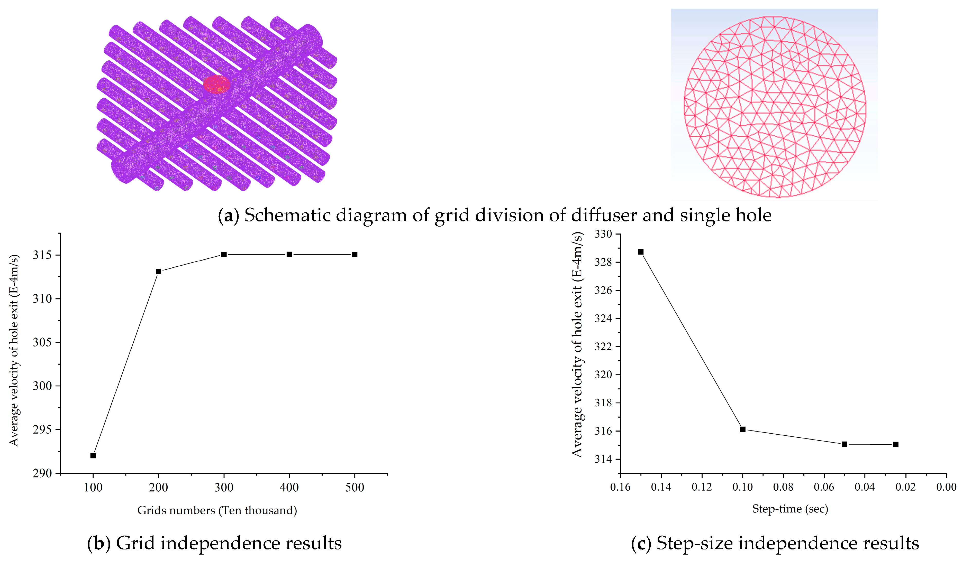
Figure 2a shows the grid model of a diffuser. It uses the average velocity of the hole exit to verify the influence of grid number on the calculation results, as shown in Figure 2b. It can be seen from Figure 2b that the calculation result is less affected by the computational grid of more than 3.00 million. We are setting 3.49 million grids for the calculation to improve the calculation speed and accuracy. The time steps were taken in the ranges of 0.01–0.05 s, 0.05–0.1 s, and 0.1–0.15 s, respectively, and the step independence was verified when the time steps were 0.02 s, 0.05 s, 0.1 s, and 0.15 s, respectively, as shown in Figure 2c. When the step length time is 0.05 s, the speed can be considered stable. The calculation period will increase significantly if the step size is too small. Otherwise, the calculation accuracy will be affected. Taking comprehensive consideration, the calculated time step size is 0.05 s in this paper.
We are setting the inlet velocity, inlet pressure, and dynamic viscosity of water by setting inlet conditions during simulation calculation. Only the inlet diameter of the diffuser and the distance and diameter of holes on the diffuser are related to the structure. We are designing the orthogonal experiments for the 4-factor and 3-level problems. Table 1 shows nine diffuser structure parameters according to the test scheme. The different diffuser models are established according to different structural parameters and simulated by Ansys Fluent.
According to the calculation results of numerical simulation, the flow data of each diffuser hole under different working conditions is obtained. Then, the non-uniformity coefficient can be calculated according to Equation (1), as shown in Table 2.
The professional fitting software “1stopt 5.0” is applied to fit the non-uniform coefficient and structural parameters according to Equation (7). The prediction correlation formula of non-uniform coefficient is obtained finally, as shown in Equation (8).
ξ = 3.2 × 10 7 × ( λ D ) 1.036 × ( d D ) - 0.6056 × ( μ uD p ) 2.649

2.4. Influence of Inlet Velocity on Non-Uniformity Coefficient

Figure 3 shows the variation of the non-uniformity coefficient of 9 kinds of diffusers with the change of inlet velocity. Figure 3 shows that the maximum non-uniform coefficient is close to 80%, the minimum is only about 5%, and the difference is about 75%. When the flow velocity is in the range of 0.01–0.1 m/s, the non-uniformity coefficient is greatly affected by the increase of flow velocity. This is because the flow difference between the diffuser holes will fluctuate significantly with the rise in inlet velocity when the channel is unfilled.
When the flow velocity comes to the range of 0.1–0.5 m/s, the channel will gradually fully fill with water. Figure 3 also shows that the flow rate through each diffuser hole tends to be consistent when the inlet velocity is 0.5 m/s, leading to uniform diffuser pressure. If the inlet velocity continues to increase, the water in the channel will display the jet phenomenon, and the pressure difference under each diffuser hole will increase due to the flow rate change of each diffuser hole, which will eventually lead to the change of the non-uniformity coefficient. In order to make the study more representative, we selected the inlet velocity under stable conditions (that is, the inlet velocity was 0.5 m/s) for subsequent calculations.

2.5. Experimental Verification

In order to verify the accuracy of the flow rate of each hole obtained by numerical simulation, experiments were carried out. The flow rate of each hole of the No. 8 diffuser was measured at different flow rates. If the flow value of the corresponding hole measured by experiment and numerical simulation is within the allowable range of error, it shows that the numerical simulation results are accurate, and the derived non-uniformity coefficient Formula (8) is also correct.

2.5.1. Experimental System and Operation Process

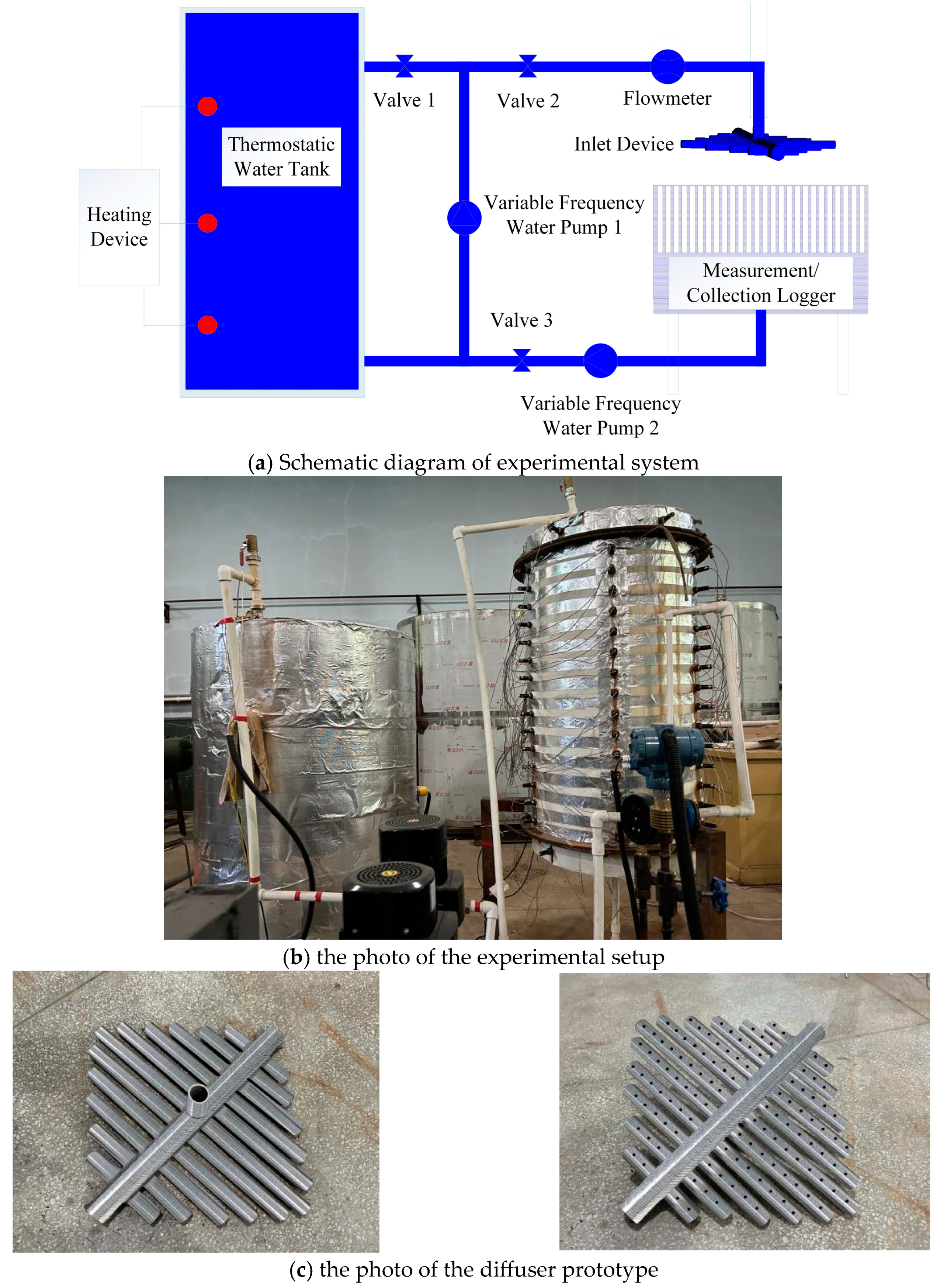
Figure 4a is a schematic diagram of the experimental system, including a thermostatic water tank, water pump, flow meter, hand valve, diffuser, and flow measurement/collection device. All the pipes have the same diameter so that the whole circulation loop can be regarded as a uniform flow system. It also shows the photo of the experimental setup and the diffuser prototype in Figure 4b,c. The height of the heat storage tank is 1220 mm and the diameter of the bottom of the tank is 750 mm. The two most important measurement devices include a graduated container and stopwatches. Figure 4a shows the data collection system as a measurement/collection logger. The grid object is the graduated container pasted on barbed wire. Each graduated container accurately fits the water outlet holes of the diffuser. After the test, the water flow of each hole can be measured by reading the scale of the graduated container and weighing the weight of water in the graduated container.
As an important variable, the hot water temperature should be kept uniform and stable during operation (i.e., the longitudinal temperature difference is lower than 0.5), so use the thermostatic water tank for circulating heating to maintain the water temperature. The hot water enters from the inlet of the diffuser, flows out from the holes, and finally returns to the collecting device. The graduated cylinder measures the flow rate of each hole. To ensure the constant inlet flow rate during operation, the opening of the manual valve is always unchanged. Record the total inlet flow rate and the flow rate of each hole every 10 s and take the average value of the flow rate data of holes 5–8 times as the final result.
Set the initial hot water temperature at 90 °C, and the inlet flow velocity is controlled at 0.5 m/s and 0.9 m/s, respectively. Carry out three times for each working condition to achieve the accuracy of the experiment. The experimental procedure is as follows:
  • Set the flow rate to the desired value. Open pump 1 and valve 2. Achieve the target flow by adjusting the pump 1 frequency and the valve 2 opening. When the flow reaches, keep the valve 2 opening unchanged and turn off water pump 1.
  • Close valve 2, then open the heating equipment and pump 1, and heat the water to 90 °C. Stop heating when the measured temperature difference in the longitudinal direction is lower than 0.5 °C. At this time, the constant temperature water tank has a uniform temperature field.
  • Begin the experiment; valve 2 is opened, valve 1 and 3 are closed. Collect the flow rate of each hole.

2.5.2. Experimental Error and Sensitivity

According to the experimental operation process in Section 2.5.1, the experimental data of each hole of the No. 8 diffuser were measured under the conditions of initial hot water temperature of 90 °C and inlet velocity of 0.9 m/s. Take the average value of the flow rate data of holes for 5 times in 10 s as final results. The 2.3 section numerical simulation method is used to restore the experimental process, and the numerical simulation results are obtained. The experimental flow data and numerical simulation results are compared to verify the accuracy of the numerical simulation. Considering the symmetry of the diffuser, only the left half of the data are given. The experimental flow data and numerical simulation data are shown in Table 3.
The flow rate data of each hole measured by the experiment is compared with the data obtained by numerical simulation. The relative error ε is as follows:
ε = x m x c x m × 100 %
x m —The flow rate of each diffuser hole measured by experiment, kg/s
x c —The flow rate of each diffuser hole calculated by numerical simulation, kg/s
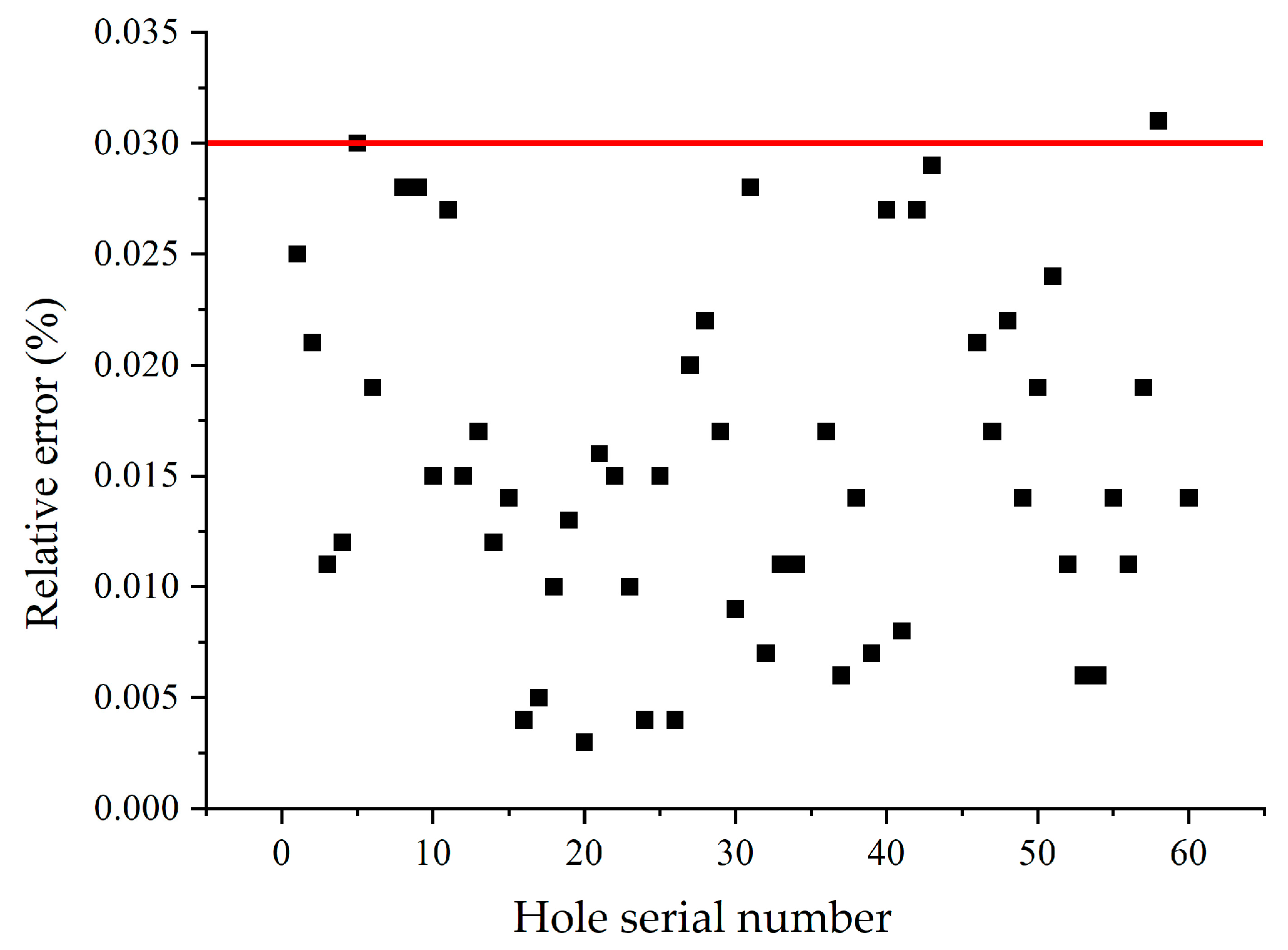
Relative error is a dimensionless value, which can better reflect the reliability of measurement. As shown in Figure 5, the relative error ε of all hole flows is within 3%. Therefore, the flow rate of each hole obtained by numerical simulation has higher accuracy. So, the non-uniformity coefficient of the diffuser according to the holes flow rate is correct.

3. Relationship of Non-Uniformity Coefficient, Temperature Stratification, and Exergy Efficiency

We numerically simulated the thermal performance of thermal storage tanks equipped with different tube-shaped diffusers to explore the consistent relationship of non-uniformity coefficient, temperature stratification, and exergy efficiency. In this paper, the diameter and height of the heat storage tank are 0.75 m × 1.22 m. Table 1 shows nine kinds of tube-shaped diffusers with different parameters respectively arranged at the inlet of the heat storage tank. Figure 1 shows the installation position.
When the inlet flow velocity is u = 0.5   m / s , the temperature stratification of nine kinds of heat storage tank is obtained as shown in Figure 6 at τ * = 0.25 . The dimensionless time τ * is defined as follows:
τ * = τ actual τ
τ * —The dimensionless time, reflects the rate of charging/discharging in terms of time
τ actual —The time elapsed from the moment the water entered, s
τ —The time required to replace all the water in the tank, s
The temperature stratification is the middle area between hot water and cold water, which is caused by the different density of cold and hot water. The thickness of the temperature stratification is expressed by the difference of the dimensionless height H * , namely, the relative height difference between the upper and lower boundaries of the temperature stratification. The dimensionless height H * is defined as: H * = H ideal H , H * reflects the heat charging/discharging progress of the water tank in space. H ideal reflects the position height of the hot- and cold-water interface in the ideal layered state.
Figure 6 shows that the thickness of temperature stratification in nine kinds of heat storage tanks differ due to the influence of varying diffuser structures. The diffuser with a good water distribution effect will reduce the intensity of mixing cold and hot water. In contrast, the diffuser with non-uniform water distribution will produce local turbulence to mix more cold and hot water, which makes the temperature stratification thicker.
Therefore, Figure 6a indicates that the thickness of temperature stratification formed by a 4# diffuser is only 0.182, while it is 0.553 formed by 8# diffuser, which is 3.02 times that created by a 4# diffuser. At the same time, Table 2 shows that the non-uniformity coefficient of the 4# diffuser is 3.39%, while that of the 8# diffuser is 75.17%. The increase in the non-uniformity coefficient leads to a uniform flow rate in each diffuser hole, which results in a significant difference in temperature stratification thickness. The larger the non-uniformity coefficient, the thicker the temperature stratification.
The exergy efficiency is defined in Figure 11 according to reference [28].
η e * = E * x , actual E * x , ideal
η e * —The exergy efficiency, %
η e * E x , actual —The exergy amount in actual layering process, J
η e * E x , ideal —The exergy amount in ideal layering process, J
In practical applications, only hot water above the specified temperature in the heat storage tank can be used, so the exergy amount is defined in Figure 12 according to reference [29].
E x * = C p i = 1 n K i [ m i ( T i T R E G ) + m i T R E G I n ( T R E G T i ) ] ,   K i = 1 T i > T R E G 0 T i < T R E G
m i —The water quality of layer i, kg/s
T R E G —The minimum temperature region of the heat storage tank allowing to release, K
K i —The actual water utilization coefficient of layer i
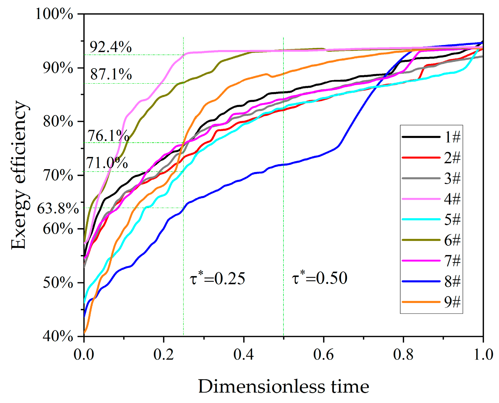
Figure 7 shows the variable law of charging exergy efficiency in heat storage tank with time. Among the nine diffusers, the efficiency of the heat storage tank installed with the No. 4 and No. 6 diffuser is always high, and the efficiency of the heat storage tank installed with the No. 8 diffuser is always the lowest. It can be clearly seen from Figure 7 that when τ * = 0.25 , the exergy efficiencies of heat storage tanks with No. 4 and No. 8 diffusers are 92.4% and 63.8%, respectively, and the difference is close to 30%. In addition, the time required for the thermal storage tank with the No. 4 diffuser to reach the peak efficiency is about half of that of No. 6. The initial exergy efficiency of the heat storage tank with the No. 9 diffuser is the lowest, and the increment of exergy efficiency is the largest during the whole operation process. The exergy efficiency of the heat storage tanks installed with the remaining diffusers all peaked at the end of the charging process, and the change rules were similar.
The reason is that the mixing situation of cold and hot water caused by different diffusers is different. So, the corresponding temperature stratification also leads to additional exergy efficiency. However, this disturbance influence will gradually decrease and disappear in the longitudinal direction with time. According to the peak regulation characteristics of the heat storage tank in the heating unit, the shorter the optimal stratification time, the shorter the dynamic response time, the greater the flexibility of the peak regulation unit. Therefore, the thermal performance the thermal storage tank is the best with the 4# diffuser ( ξ = 3.39 % ). The smaller the non-uniformity coefficient, the larger the exergy efficiency.
To further verify that the non-uniformity coefficient is suitable for evaluating different types of diffusers, the octagonal and flat diffusers are analyzed, as shown in Figure 8. The non-uniformity coefficients ξ of octagonal diffusers are 21.08%, 40.97%, and 53.77%, respectively. The non-uniformity coefficients ξ of flat-plate diffusers are 21.08%, 38.70%, and 45.69%, respectively. The settings of all numerical simulation conditions are the same as that of the previous tube-shaped diffuser. Figure 9 and Figure 10 are the migration diagrams of the temperature stratification in the heat storage tank when the octagonal and flat-plate diffusers’ non-uniformity coefficient is 21.08%. It can be seen from Figure 9 and Figure 10 that the temperature stratification of the octagonal diffuser is thinner, and the temperature stratification produced by the two diffusers gradually increases with time.

4. Universality Verification of Evaluation Method

The reason is that a diffuser with superior performance can inhibit the convection of cold and hot water to a certain extent and create a stable temperature stratification. However, heat conduction in the longitudinal direction still exists. The higher temperature water continuously transfers energy to the lower temperature water, and the temperature stratification gradually expands and thickens.
Figure 11 shows the exergy efficiency of the heat storage tank corresponding to the octagonal diffuser with three different non-uniformity coefficients ( ξ = 21.08%, 48.76%, 53.77%). Figure 11 shows that the two types of diffusers with larger ones have higher exergy efficiency. However, the superior performance of the diffuser non-uniformity coefficients with 21.08% makes the exergy efficiency increase faster than others with time. The smaller the non-uniformity coefficient, the higher the exergy efficiency is. The exergy efficiency of non-uniformity coefficients with 21.08% is more elevated, 5.01% and 11.19%, than that of the other two diffusers.
Figure 12 shows the exergy efficiency of the heat storage tank corresponding to the flat diffuser with three different non-uniformity coefficients ( ξ = 21.08%, 38.70%, 45.69%). It can be seen from Figure 12 that there is still a good consistency between the non-uniformity coefficient and the exergy efficiency. That is because the decrease of ξ indicates that the structural parameters of the diffuser tend to be reasonable, so the corresponding exergy efficiency also increases. And as heat storage progresses, the gap of non-uniformity coefficient caused by the change gradually increases. The maximum gap between the exergy efficiency of the three types of diffusers is 12.09% at τ * = 0.9 T .

5. Conclusions

Based on Buckingham’s theorem, a new evaluation index, namely the non-uniformity coefficient of water distribution, is proposed to evaluate the water distribution effect of diffuser. Three structure factors of diffusers, such as the diameter of the inlet pipe with diffuser, the distance, and the diameter of a diffuser, are considered. The calculation method of non-uniformity coefficient is given, which is suitable for evaluating different types of water distributors. The variation of non-uniformity coefficient is in good agreement with the variation of temperature stratification and exergy efficiency of heat storage tanks. The heat storage tank with good distribution uniformity diffuser forms thin temperature stratification and relatively high exergy efficiency. The experimental results verify the accuracy of the non-uniformity coefficient, which is used to evaluate the performance of the diffuser in the heat storage tank. The numerical results show that the non-uniformity coefficient of the No. 4 diffuser is 3.39%, while the temperature stratification is the thinnest and exergy efficiency is the highest (up to 92.4%). When the flow rate of the diffuser is 0.5 m/s, the temperature stratification produced by the No. 8. diffuser (the non-uniformity coefficient is 75.17%) is three times that of the No. 4 diffuser, which directly leads to an exergy efficiency reduction of nearly 30%. This paper provides a theoretical and experimental basis for the structural design and selection of diffusers for heat storage tanks.

Author Contributions

Conceptualization, J.Y.; Methodology, L.C. and J.Y.; Software, X.L. and Z.W.; Formal analysis, X.L.; Investigation, L.C.; Resources, J.Y.; Data curation, Z.W.; Writing—original draft, J.Y. and X.L.; Writing—review & editing, L.C. All authors have read and agreed to the published version of the manuscript.

Funding

This research received no external funding.

Data Availability Statement

Data are contained within the article.

Conflicts of Interest

The authors declare no conflict of interest.

Nomenclature

Nomenclature Symbols pPressure/MPa
ξ Non-uniformity coefficient/% Q i Mass flow rate/kg/s
η e Exergy efficiency Q ¯ Average mass flow rate /kg/s
λHole distance/mmReReynolds number
μWater dynamic viscosity/Pa·sTTemperature/K
α , β , γ , ε , θ , κ dimensional coefficient of each parameterxFlow rate/kg/s
ε Relative errorSubscripts
τ Time/min*Dimensionless
uWater flow velocity/m/sactualActual stratification process
dHole diameter/mmcCalculation result
DInlet diameter of diffuser/mmmMeasured result
E x the amount of exergy/JiSubstitute symbol of hole number
HHeight/midealIdeal stratification process
kBasic coefficient of solutionAbbreviations
nTotal number of holesCFDComputational Fluid Dynamics

References

  1. Han, Y.; Wang, R.; Dai, Y. Thermal stratification within the water tank. Renew. Sustain. Energy Rev. 2009, 13, 1014–1026. [Google Scholar] [CrossRef]
  2. Wang, Z.; Zhang, H.; Dou, B.; Huang, H.; Zhang, G. The thermal stratification characteristics affected by a novel equalizer in a dynamic hot water storage tank. Appl. Therm. Eng. 2017, 126, 1006–1016. [Google Scholar] [CrossRef]
  3. Gajbhiye, P.; Salunkhe, N.; Kedare, S.; Bose, M. Experimental investigation of single media thermocline storage with eccentrically mounted vertical porous flow distributor. Sol. Energy 2018, 162, 28–35. [Google Scholar] [CrossRef]
  4. Pilotelli, M.; Grassi, B.; Lezzi, A.; Beretta, G. Flow models of perforated manifolds and plates for the design of a large thermal storage tank for district heating with minimal maldistribution and thermocline growth. Appl. Energy 2022, 322, 119436. [Google Scholar] [CrossRef]
  5. Shah, L.J.; Furbo, S. Entrance effects in solar storage tanks. Sol. Energy 2003, 75, 337–348. [Google Scholar] [CrossRef]
  6. Tang, J.; Shi, Y.; Ouyang, Z. Optimization design of the octagonal water diffuser with uniform flow orifice plate. J. Energy Storage 2021, 44, 103374. [Google Scholar] [CrossRef]
  7. Karim, M. Experimental investigation of a stratified chilled-water thermal storage system. Appl. Therm. Eng. 2011, 31, 1853–1860. [Google Scholar] [CrossRef]
  8. Weiss, J.; Ortega-Fernández, I.; Müller, R.; Bielsa, D.; Fluri, T. Improved thermocline initialization through optimized inlet design for single-tank thermal energy storage systems. J. Energy Storage 2021, 42, 103088. [Google Scholar] [CrossRef]
  9. Wang, L.; Zhang, H.; Wang, C.Y.; Yan, Q.W. Study of the influence of new type water inlet structure on the characteristics of a solar power stratified water tank. J. Eng. Therm. Energy Power 2016, 31, 124–128. [Google Scholar] [CrossRef]
  10. Kozłowska, K.; Jadwiszczak, P. The impact of inflow velocity on thermal stratification in a water storage tank. E3S Web Conf. 2018, 44, 00079. [Google Scholar] [CrossRef]
  11. Zhang, S.F.; Tang, C.Q.; Chen, Z.Q. Simulation study of the velocity field of naturally stratifitied chilled water storage tank diffuser. J. Chongqing Univ. 2011, 34, 13–16. [Google Scholar] [CrossRef]
  12. Cherry, E.M.; Padilla, A.M.; Elkins, C.J.; Eaton, J.K. Three-dimensional velocity measurements in annular diffuser segments including the effects of upstream strut wakes. Int. J. Heat Fluid Flow 2010, 31, 569–575. [Google Scholar] [CrossRef]
  13. Li, S.-H.; Zhang, Y.-X.; Li, Y.; Zhang, X.-S. Experimental study of inlet structure on the discharging performance of a solar water storage tank. Energy Build. 2014, 70, 490–496. [Google Scholar] [CrossRef]
  14. Ge, Z.H.; Zhang, F.Y.; Zhang, Y.J. Simulation on performance improvement of single thermocline energy storage tank. Proc. CSEE039 2019, 3, 773–781. [Google Scholar] [CrossRef]
  15. Fernández-Seara, J.; Uhı’a, F.J.; Sieres, J. Experimental analysis of a domestic electric hot water storage tank. Part II: Dynamic mode of operation. Appl. Therm. Eng. 2007, 27, 137–144. [Google Scholar] [CrossRef]
  16. García-Marí, E.; Gasque, M.; Gutiérrez-Colomer, R.P.; Ibáñez, F.; González-Altozano, P. A new inlet device that enhances thermal stratification during charging in a hot water storage tank. Appl. Therm. Eng. 2013, 61, 663–669. [Google Scholar] [CrossRef]
  17. Li, S.H.; Wen, C.; Zhang, X.S.; Zhou, X. Effect of inlet structure on discharging performance of solar storage tank. Acta Energiae Solaris Sin. 2013, 34, 670–675. [Google Scholar] [CrossRef]
  18. Hegazy, A.A. Effect of inlet design on the performance of storage-type domestic electrical water heaters. Appl. Energy 2007, 84, 1338–1355. [Google Scholar] [CrossRef]
  19. Lou, W.; Xie, B.; Aubril, J.; Fan, Y.; Luo, L.; Arrivé, A. Optimized flow distributor for stabilized thermal stratification in a single-medium thermocline storage tank: A numerical and experimental study. Energy 2023, 263, 125709. [Google Scholar] [CrossRef]
  20. Szczęśniak, A.; Milewski, J.; Dybiński, O.; Futyma, K.; Skibiński, J.; Martsinchyk, A.; Szabłowski, Ł. Determination of Thermocline Heat Transfer Coefficient by Using CFD Simulation. Energies 2023, 16, 3150. [Google Scholar] [CrossRef]
  21. Toh, K.H.B.; Lim, E.W.C. Dimensionless numbers and correlations for characterizing heat transfer in a pulsating fluidized bed. Appl. Therm. Eng. 2019, 153, 448–462. [Google Scholar] [CrossRef]
  22. Ekici, C.; Teke, I. Developing a new solar radiation estimation model based on Buckingham theorem. Results Phys. 2018, 9, 263–269. [Google Scholar] [CrossRef]
  23. Misic, T.; Najdanovic-Lukic, M.; Nesic, L. Dimensional analysis in physics and the Buckingham theorem. Eur. J. Phys. 2010, 31, 893–906. [Google Scholar] [CrossRef]
  24. Ciulla, G.; D’amico, A.; Brano, V.L. Evaluation of building heating loads with dimensional analysis: Application of the Buckingham π theorem. Energy Build. 2017, 154, 479–490. [Google Scholar] [CrossRef]
  25. Haftkhani, A.R.; Arabi, M. Improve regression-based models for prediction of internal-bond strength of particleboard using Buckingham’s pi-theorem. J. For. Res. 2013, 24, 735–740. [Google Scholar] [CrossRef]
  26. Wang, Z.; Zhang, H.; Dou, B.; Huang, H.; Wu, W.; Wang, Z. Experimental and numerical research of thermal stratification with a novel inlet in a dynamic hot water storage tank. Renew. Energy 2017, 111, 353–371. [Google Scholar] [CrossRef]
  27. Yaïci, W.; Ghorab, M.; Entchev, E.; Hayden, S. Three-dimensional unsteady CFD simulations of a thermal storage tank performance for optimum design. Appl. Therm. Eng. 2013, 60, 152–163. [Google Scholar] [CrossRef]
  28. Szczęśniak, A.; Milewski, J.; Dybiński, O.; Futyma, K.; Skibiński, J.; Martsinchyk, A. Dynamic simulation of a four tank 200 m3 seasonal thermal energy storage system oriented to air conditioning at a dietary supplements factory. Energy 2023, 264, 126106. [Google Scholar] [CrossRef]
  29. Wang, C.Y.; Zhang, H.; Wang, Z.L. Research status on stratification of hot water storage tank. Chin. J. Refrig. Technol. 2016, 36, 5. [Google Scholar] [CrossRef]
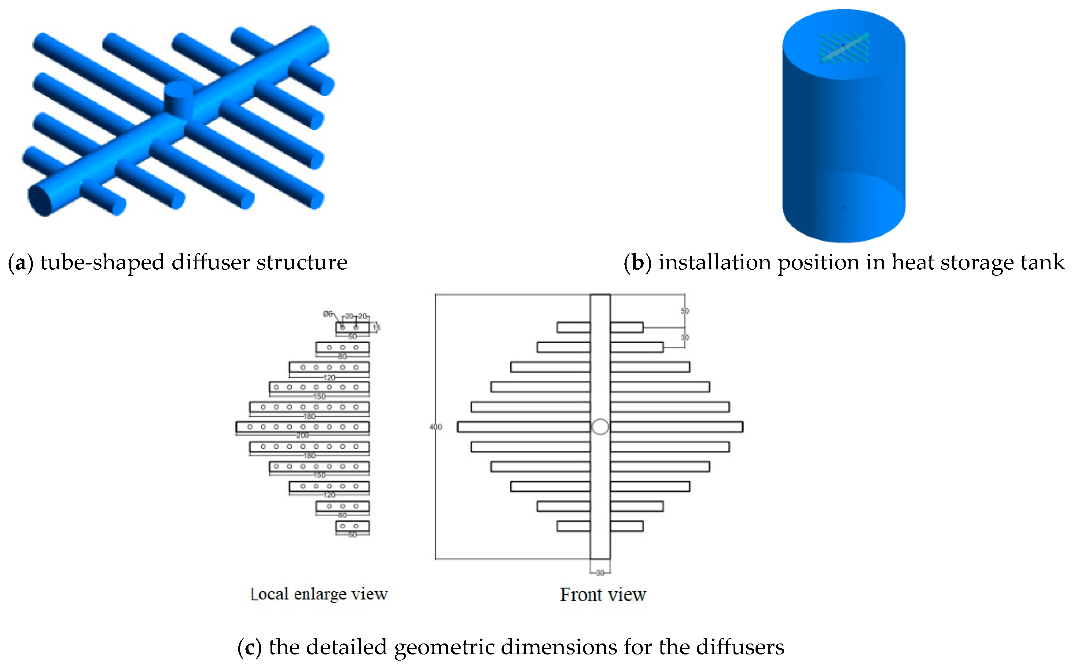
Figure 1. Model of tube-shaped diffuser, the detailed geometric dimensions for the diffuser, and its installation position in heat storage tank.
Energies 17 00618 g001
Figure 2. Schematic diagram of grid division, grid independence analysis, and step-size independence analysis of diffuser.
Energies 17 00618 g002
Figure 3. Velocity Variation of non-uniformity coefficient of diffuser with inlet velocity.
Energies 17 00618 g003
Figure 4. Schematic diagram of experimental system.
Energies 17 00618 g004
Figure 5. Error analysis of experimental and numerical simulation.
Energies 17 00618 g005
Figure 6. Temperature distribution of heat storage tank with different diffusers.
Energies 17 00618 g006
Figure 7. Change of exergy efficiency over time.
Energies 17 00618 g007
Figure 8. Imitation octagonal diffuser and flat diffuser.
Energies 17 00618 g008
Figure 9. Temperature stratification under octagonal diffuser.
Energies 17 00618 g009
Figure 10. Temperature stratification of flat diffuser.
Energies 17 00618 g010
Figure 11. Exergy efficiency change with octagonal diffuser.
Energies 17 00618 g011
Figure 12. Exergy efficiency change with flat diffuser.
Energies 17 00618 g012
Table 1. Structural parameters of diffuser.
Serial NumberInlet Diameter
(mm)
Hole Diameter
(mm)
Hole Distance
(mm)
1#20630
2#20840
3#30850
4#40650
5#40830
6#30640
7#201050
8#301030
9#401040
Table 2. Data of the non-uniformity coefficient.
Boundary Conditionsp1 = 101,500 Pa T = 363 K
The Serial Number u = 0.01 m/su = 0.1 m/su = 0.5 m/su = 0.9 m/su = 2.0 m/s
1#46.66%53.37%53.77%49.98%58.08%
2#45.54%39.49%48.76%56.9%70.37%
3#15.50%15.89%19.96%15.71%13.32%
4#4.24%8.64%3.39%6.85%6.36%
5#37.76%40.81%35.98%38.54%42.45%
6#17.54%21.87%13.31%12.36%13.38%
7#50.08%47.07%58.86%55.79%45.12%
8#77.15%72.71%75.17%78.02%80.02%
9#36.47%44.05%36.21%40.49%34.46%
Table 3. Flow rate of each hole of No. 8 diffuser.
Serial NumberExperimental Measurement
(ml/s)
Numerical Simulation Result
(ml/s)
Serial NumberExperimental Measurement
(ml/s)
Numerical Simulation Result
(ml/s)
Serial NumberExperimental Measurement
(ml/s)
Numerical Simulation Result
(ml/s)
Serial NumberExperimental Measurement
(ml/s)
Numerical Simulation Result
(ml/s)
136.0 35.11620.7 20.83136.0 35.04626.1 25.6
234.2 34.9 1718.9 19.03237.8 37.54726.126.6
324.3 24.61827.0 26.73332.4 32.04836.9 37.7
430.6 30.21928.8 28.43424.3 24.64931.531.1
527.0 26.22035.1 35.03517.1 18.95028.828.3
623.4 23.02136.9 36.33625.2 24.85122.523.0
736.9 35.1 2238.7 38.13727.9 28.15225.224.9
828.8 28.02330.6 30.33831.5 31.15327.927.7
925.2 24.5 2424.3 24.23938.7 38.45428.829.0
1023.4 23.02523.4 23.04033.3 32.45525.224.8
1127.0 26.3 2621.6 21.54134.2 33.95629.730.0
1231.5 31.02722.5 22.14227.0 26.35727.927.4
1335.1 34.52828.8 28.24327.9 28.75826.125.3
1428.8 28.52936.0 36.64425.2 23.45927.935.1
1563.0 62.13038.7 38.34510.8 18.1
Disclaimer/Publisher’s Note: The statements, opinions and data contained in all publications are solely those of the individual author(s) and contributor(s) and not of MDPI and/or the editor(s). MDPI and/or the editor(s) disclaim responsibility for any injury to people or property resulting from any ideas, methods, instructions or products referred to in the content.