Review

A Review on Flow Boiling Enhancement on Textured Surfaces

by
Frederik Mertens
1,
Sylvie Castagne
2 and
Maria Rosaria Vetrano
1,*
1
Department of Mechanical Engineering, Division of Applied Mechanics and Energy Conversion (TME), KU Leuven, B-3001 Leuven, Belgium
2
Department of Mechanical Engineering, Division of Manufacturing Processes and Systems (MaPS) and Flanders Make@KU Leuven M&A, KU Leuven, B-3001 Leuven, Belgium
*
Author to whom correspondence should be addressed.
Energies 2024, 17(3), 558; https://doi.org/10.3390/en17030558
Submission received: 22 December 2023 / Revised: 15 January 2024 / Accepted: 18 January 2024 / Published: 23 January 2024
(This article belongs to the Section J1: Heat and Mass Transfer)

Abstract

:
It is widely established that flow boiling, being a direct cooling technique also employing the latent heat of the fluid, has the potential to be more efficient than being useful in single-phase conventional cooling methods. This results in considerable potential for thermal management in many fields like microelectronics, space technology, thermal power plants, etc. The increasing demand for heat dissipation, consequent to component miniaturization, has pushed the development of new strategies for enhancing heat transfer efficiency, such as employment of functionalized surfaces. This review aims to describe in detail the current status of technology related to flow boiling heat transfer enhancement via micro/nanoscale surface functionalization. Key objectives are an increased nucleation site density and enhanced bubble dynamics. The vast majority of findings show favorable heat transfer performance, evidenced by an earlier onset of boiling (ONB), an improved flow boiling heat transfer coefficient (HTC), and an ameliorated critical heat flux (CHF). Increased pressure drop is a serious concern in certain application cases. Nanoscale textures mainly enhance capillary wicking to nucleation sites, thus being more effective in combination with microscale textures that define fixed nucleation sites. Degradation effects need to be more thoroughly and systematically characterized for application cases. Extra effects related to the manufacturing process can be easily overlooked, but one should be aware of their possible existence when drawing conclusions. Finally, the implementation of enhanced surfaces in mainstream applications is hindered by the absence of general predictive design tools for different channel configurations/materials, fluids, and operating conditions. A more universal understanding of the basic mechanisms involving texture geometry is needed in this aspect.

1. Introduction

It is a fact that developing efficient cooling–heating devices is a crucial task in many disciplines, among which, for example, is heat dissipation in electronics. The observed rapid increase in packing density of electronic components and their continuous decrease in size has led to a strong need for advanced thermal management strategies. One is the use of mini- or microchannel heat sinks combining fluid phase change and convective heat transfer via flow boiling. However, the exponential increase in produced heat flux at the chip level strongly limits further system miniaturization. Also, from an environmental point of view, the use of refrigerants poses issues regarding their Global Warming Potential (GWP) and production costs. A different strategy to enhance heat transfer during flow boiling is the functionalization of the inner surface of the channels through which the coolant flows. In the last 20 years, with the advent of new manufacturing technologies and the advances in material sciences, we have observed an increasing number of research activities and scientific literature focused on surface functionalization for heat transfer applications. Modification of the hot surface creates cavities that may increase nucleation site density and enhance bubble growth and detachment, thus improving heat transfer. Many surface modification techniques have already been developed and investigated. Direct coating methods such as electrochemical deposition, chemical vapor deposition, and direct powder sintering have been studied, and remarkable enhancements in boiling heat transfer coefficients and critical heat fluxes were reported. On the other hand, intrinsic surface features developed using MEMS/NEMS technologies, CNC machining, additive manufacturing (AM), and other advanced manufacturing techniques have also achieved significant boiling heat transfer augmentation. However, despite the degrees of boiling enhancement, a common factor here is the scalability of these techniques to produce enhanced surfaces on a larger scale and at a low cost.
The beneficial effects of some surface modification techniques on flow boiling have been reported in the literature. These techniques include macroscale (>1 mm), microscale (1–1000 µm), nanoscale (<1 µm) and even multiscale features [1]. These dimensional modifications are each accompanied by a distinctive characteristic that increases boiling performance. The improvements of these adjustments include an increase in heat transfer area (macroscale), a higher nucleation site density (microscale), and improved capillary wicking effects (nanoscale). Changing the texture of a heat-dissipating surface thus facilitates the enhancement of the nucleate boiling heat transfer and affects the critical heat flux. However, the required adaptations for increased nucleate heat transfer performance differ from those needed for a higher CHF. Also, the choice of working fluid has a significant impact. The desired effects thus have to be clearly addressed [1,2]. This paper aims to critically review recent developments in improving flow boiling heat transfer via microscale and nanoscale features. The various methods employed to fabricate these surfaces and their levels of enhancements are elaborated, and the effects of enhanced surfaces on the bubble dynamics in different fluids, including water and dielectric fluids, are examined. Based on the literature surveyed, existing shortfalls and areas which require further investigation are identified.

2. Microscale Textures

2.1. Microscale Fins

Many researchers have explored the use of micro-pin fins as a way to improve flow boiling heat transfer. Analyzed parameters include pin size, shape, and spacing/pattern. An example is given in Figure 1.
Ma et al. [4] used dry etching to fabricate square micro pin fins with a thickness of 30 µm, a spacing or “fin pitch” of twice the thickness, 60 µm, and heights of 60 and 120 µm directly on chip surfaces for cooling using FC-72. Their micro pin finned surfaces showed considerable heat transfer enhancement and an increased CHF compared to the smooth surface for the same velocity and subcooling. CHF values further increased with fluid velocity and subcooling for all surfaces. As expected, the surface with the highest fins resulted in the highest achieved heat transfer. The wall temperature of the micro pin finned surfaces was lower than the upper temperature limit of 85 °C associated with a normal chip operation.
Wei et al. [5] also conducted flow boiling experiments on a silicon chip with dry-etched square micro pin fins with dimensions (width, height) of 30 × 60, 30 × 120, 50 × 60, 50 × 120 µm and a spacing (fin pitch) of twice the fin width. They performed subcooled flow boiling of FC-72 at different velocities and degrees of subcooling. Intuitively, their results showed that increasing the total surface area could enhance the boiling heat transfer. The enhancement mechanism was proposed to be related to bubble inception at the fin root and its growth in the confined space between the fins. This led to a thin liquid layer on the fin sidewalls, which can evaporate with a very high heat transfer coefficient. Also, micro-convection, caused by thermocapillary force due to the suction of a bubble growing further on the top of micro pin fins, was included in the reasoning as it provides a driving force for fresh liquid motion in proximity to the fins. The capillary force increases with decreasing fin pitch but causes the hydraulic resistances of the liquid supply to increase. Therefore, an optimum fin pitch for a compromise exists. Using previous pool boiling studies [6], the researchers found that a fin gap of 30–50 µm appeared preferable. As a conclusion from their findings, increasing the fin area is beneficial, but at the highest tested flow rate of 2 m/s, the 30 × 120 µm variant performed better than the 50 × 120 µm one, as it reached higher CHF and lower wall superheat. This again shows that an optimal size and spacing depends on the desired system operating conditions.
Guo et al. [7] used dry-etched chip micro pin fins of (width/gap × height) 30 × 60, 30 × 120, 50 × 60, 50 × 120 µm to conduct subcooled flow boiling with the addition of simultaneous perpendicular jet impingement of FC-72. Three crossflow velocities (0.5, 1, 1.5 m/s) and three different jet velocities (0, 1, 2 m/s) were examined. Both the microstructures and jet impingement provided significant heat transfer enhancement. The authors showed that boiling heat transfer could be enhanced by increasing total surface area and jet impingement velocity. It was postulated that large jet impingement velocity caused more turbulence and micro-convection, reducing boundary layer thickness, which enhanced heat transfer at a high heat flux and delayed the occurrence of CHF. It was also observed that for the same jet impingement velocity (2 m/s), a decreasing cross-velocity (from 1.5 to 0.5 m/s) resulted in lesser jet suppression, leading to lower wall superheats but sacrificing a portion of CHF enhancement. A combination of low cross-velocity and high jet velocity was presented as a possibility to provide a more effective and economical method for nucleate boiling. The 50 × 120 µm pin fins presented the best performance of the tested samples. It was considered that the fin gap of 30µm chips could generate a larger flow resistance for micro-convection around the fin sidewalls, resulting in a lower heat transfer performance than that of 50 µm chips.
Krishnamurthy et al. [8] conducted subcooled and saturated flow boiling experiments of HFE-7000 along a single row of 24 inline circular 100 µm diameter micro pin fins with a lower cross-flow velocity entrenched in a microchannel. The authors observed enhancement in the heat transfer coefficient compared to that of a plain microchannel. The enhancement was higher with increasing Reynolds number and was attributed to a wake interaction between the pin fins and better fluid mixing, disrupting the boundary layer.
Tullius et al. [9] conducted a study comparing the overall shape, size, spacing and height of the pin fins to find optimized designs. General micro pin fin findings confirm that the pin aspect ratio should be relatively large (tall and thin fins) to increase the Nusselt number. Also, when deciding on the fin shape, it is understandable that circular or ellipsoid pin fins produce the lowest friction factor, reducing created pressure drops because of a more aerodynamic shape. Triangular pin fins have the most beneficial effect on the heat transfer out of the studied geometries (circle, square, diamond, ellipse, hexagon and diamond).
Wan et al. [10] compared the performance of different pin shapes (square, diamond, circular, and streamlined) in water microchannel flow boiling experiments. Their fins were made by laser micro-milling, so this production technique’s relatively high residual roughness should not be disregarded as it may lead to additional nucleation sites. Their findings showed the best performance for square fins, followed by circular streamline and diamond shapes. In addition to the best heat transfer performance, the square fins also showed a lower pressure drop than circular and streamlined fins and displayed mitigation of flow instabilities.
Woodcock et al. [11] studied flow boiling of HFE7000 in a microchannel with a more advanced silicon micro pin fin design, calling it “Piranha Pin Fins” (PPFs) to achieve multi-phase heat transfer, without its usual unwanted side effects like large pressure oscillations and flow instabilities. The general PPFs design can be seen in Figure 2.
A symmetric foil shape is intended to provide large heat transfer areas for enhanced heat transfer without increasing the friction losses above those for plain cylinders with an equivalent diameter. Extending the tail in the wake region increases the convective heat transfer area along the sidewalls and provides significant conduction via the trailing edge of the fin. An orifice opens to a hollow chamber at the leading edge, allowing mass removal through an extraction conduit (bottom of Figure 2). The orifice is engineered to accelerate the fluid and prevent vapor expansion from the interior of the pin back into the minichannel during boiling heat transfer. Also, re-entrant cavities are fabricated only on the inside wall of the piranha pin fins to further enhance the nucleate flow boiling so that the vapor could be immediately removed. Because of the venting of the vapor from the heat sink, more of the liquid phase remains in the system, thus providing the benefits of latent heat transfer together with the stability of sensible heat transfer. PPFs are also put in a staggered pattern to guide bubbles in the wake to a downstream vent.

2.2. Laser Textured Microgrooves

Sommers and Yerkes [12] studied flow boiling of R-134a on aluminum in a rectangular channel using three different micro-structure modifications, namely photolithography and reactive ion etching (parallel grooves 17 µm wide 12 µm deep perpendicular to flow and square micro-posts nominally 17 × 17 × 12 µm in size) and laser ablation (parallel micro-grooves 50 µm wide 10 µm deep perpendicular to flow), as shown in Figure 3a. The resulting boiling curves can be seen in Figure 3b.
Superior performance was found with their laser-ablated sample, displaying heat transfer coefficients as much as 90–100% higher than a bare sample. This superior performance was attributed to enhanced nucleation from a porous layer of sintered particles formed during laser ablation. This increase in boiling heat transfer performance was then further enhanced by applying a hydrophobic coating to the surface, resulting in an additional increase of approximately 20%.
Lim et al. [13] studied flow boiling enhancement of water on copper surfaces, modified using femtosecond laser texturing. This extremely short pulse allowed for precise and scalable manufacturing without thermal damage to surrounding areas. Three different surfaces were produced and compared to a plain reference. These included Laser Induced Periodic Surface Structures (LIPPS), Micro-Groove Clustered Cavity by Low laser Fluence (MGCC-LF), and Micro-Groove covered Clustered Cavity by High laser Fluence (MGCC-HF). The self-organized LIPPS structure was created by adjacent laser tracks partially overlapping, creating sub-micron ripples perpendicular to the polarization direction of the laser. These LIPPS were superimposed on each texture made by the femtosecond laser, thus also when producing microscale grooves (MGCC). Depending on laser power (Fluence) and scanning speed conditions, different surface structures (groove depth and width in this case) could be produced. From contact angle measurements, LIPPS did not affect the contact angle with water. However, MGCC-LF was reported as hydrophobic (105°), and MGCC-HF was reported as hydrophilic (16°). Any aging effect on these values was not mentioned. MGCC-LF consisted of grooves with a width of 20–25 µm and a height of 15–18 µm, while MGCC-HF had a width of 25–35 µm and a height of 35–45 µm. LIPPS had a width of 0.2–0.6 µm and a height of 0.3–0.8 µm. To prevent oxidation of the copper during boiling, a 50 nm layer of titanium was sputtered on top of the structures after laser texturing. The authors assumed this deposited layer would not affect the nanoscale surface structures because of its low thickness. They found that LIPSS and MGCC-HF were improved over the plain reference as they could absorb higher heat fluxes under the same wall superheat, shifting the boiling curve to the left and increasing HTC, with the most significant improvement for MGCC-HF (approx. 30% at the recorded maximum, compared to 15% for the LIPPS case for a flow rate of 800 kg/m²s). Surprisingly, even though hydrophobicity is expected to be beneficial at low heat fluxes by promoting easier nucleation (higher active site density), the MGCC-LF sample was seen to significantly degrade HTC performance with respect to plain reference across the whole heat flux range (around 20% decrease in HTC at recorded maximum for a flow rate of 800 kg/m²s). This is due to the liquid rewetting being inhibited by the hydrophobicity of MGCC-HF, which makes activating the cavities formed in the micro-grooves more difficult. Regarding CHF, the MGCC-HF sample significantly increased CHF by over 30%, attributed to its hydrophilicity delaying dry-out. Bubble visualizations were also performed. Compared to the plain baseline, LIPSS resulted in a higher nucleation density, smaller bubbles, and higher departure frequency. MGCC-HF also significantly increased bubble departure frequency and produced tiny bubbles. MGCC-LF was seen to produce bigger bubbles with lower detachment frequency compared to plain reference. A mechanistic overview of bubble generation on the used surfaces can be seen in Figure 4.
Belyaev et al. [14] used laser pulses on the outside wall of stainless steel tubes to produce formations on the inner wall of different heights and diameters depending on laser power. At a laser current of 130 A, these formations were found to have the shape of a rounded cone with a dip in the center with a formation diameter of 390 microns, and pores and craters were observed with diameters ranging from 5 to 60 microns. Size distribution was most uniform in the center of the dip (approximately 15 microns). Six rows of 50 formations were applied in a checkerboard pattern. Flow boiling experiments were performed using Freon R-125 in a vertically oriented 1.1 mm diameter wide and 50 mm long channel at reduced pressures p r = p / p c r of 0.43 and 0.56 with flow rates of 200–1400 kg/m2s. Surface modification was found to have an observable effect (up to 40%) on the pressure drop in single-phase experiments. The most significant effect was observed at 0.43 bar and 1260 kg/m2s, showing 110% HTC enhancement and CHF enhancement of 22%. At p r = 0.56 , the effect of surface modification was reduced, only resulting in an HTC enhancement of 23%. Absolute HTC values were still higher for p r = 0.56 . In general, higher pressure leads to an increase in nucleation site density because of a smaller minimum cavity size needed for nucleation, thus also increasing the performance of the non-modified surface. The lesser degree of enhancement at p r = 0.56 was ascribed to the produced cavities being mainly too large for an additional effect to be noticed.

2.3. Micromachined Grooves

Das et al. [15] found that the inclination of grooves/cavities can play an essential role in improving heat transfer. Their experiments were conducted in a stirred pool using grooves at 30–45–60–90° on copper plates using wire electrical discharge machining. It was found that inclining the grooves was beneficial, and a 45° inclination came out superior, as seen in Figure 5. The authors also found that adding a “re-entrant circular pocket” at the base of the grooves further improved heat transfer by approximately 20%. Groove width was set at 250 µm, with both spacing and depth of approximately 2 mm.
Moreira et al. [16] improved HTC and CHF, reduced pressure drops, and even observed boiling inversion, reported for the first time for flow boiling. The authors employed distilled water in tapered microchannels with micro-milled dual V grooves. Their reasoning was based on the evaporation momentum force, as previously explored in pool boiling by Kandlikar et al. [17]. They effectively enabled bubbles to move transversely with respect to the flow direction, creating separated liquid and vapor pathways. This principle is shown in Figure 6.
The bottom sharp corners favor nucleation because of higher temperature. The two forces acting on the bubble trajectory are the inertial force F i and evaporation momentum force F m , with the latter scaling with the square of the heat flux, while the former being quasi-independent of it. These forces are reported in Equations (1) and (2) per unit length with G as the mass flux, ρ l as liquid density, ρ v as vapor density, q as heat flux, h v a p as latent heat of evaporation and D as characteristic length of the bubble. These forces govern the trajectory of the nucleating bubble.
F i = G 2 D ρ l ,
F m = q h v a p 2 D ρ v .
The increase of F m with the square of the heat flux was prescribed as the reason for boiling inversion. The dimensions for the best performing structure, as per the parameters in Figure 6, are W c = 265 µm, H c = 200 µm, P c = 690 µm and θ = 30 , with 15 parallel channels on a 10 × 10 mm chip area. Furthermore, the channel above this structure was tapered at 6%, increasing from 127 to 727 µm over its 10 mm length. Preferential vapor pathways were above the triangles, while the rectangles housed the preferential liquid paths.
Effects of internal angle θ were studied, showing overall heat transfer improvements for higher angles (e.g., 60 ° instead of 30 ). It was deduced that wider angles promote a larger open zone for the detachment of bubbles and that the magnitude of the projection of the net F m perpendicular to the flow is higher for wider angles. However, it was noted that wider channels can reduce rewetting capability and degrade the separation of vapor and liquid.
Effects of the flow rate were also studied, pointing to an optimal flow rate for best heat transfer performance. The researchers found that an increase in flow rate ensures the detachment of smaller bubbles and makes them follow a longer phase-change path, thus increasing heat transfer. However, high inertial forces can also prevent these bubbles from coming out of the grooves, leading to vapor blankets and subsequent heat transfer deterioration. Increases in mass flux could also lead to suppression of nucleate boiling, making single-phase convection more dominant and thus reducing HTC.
Lastly, the effect of the number of channels, and thus their density, was studied, evidencing a boiling inversion when the channels were increased from 5 to 15, as shown in Figure 7.
The evaporation momentum force that drives the bubbles away from the walls also leads to the pulling of liquid from the vicinity of active nucleation sites due to sudden bubble ejection, happening at higher velocities as the evaporation momentum force increases with heat flux. The liquid suction effectively acts as an impinging jet of liquid over the surface, thus reducing its temperature. It was mentioned that boiling inversion could occur as the magnitude of the evaporation momentum force approaches that of the inertia force. The distinct separated liquid–vapor pathways were also seen to be responsible for a decrease in pressure drop.
In conclusion, CHF and HTC enhancement of 200% with respect to plain baseline were not unusual in this study. The authors emphasized that enhancement techniques developed for pool boiling could be extended to flow boiling given proper modifications, possibly further improving both CHF and HTC.

2.4. Chemical Etching

In etching, a material is exposed to chemicals that alter surface structure. An advantage of etching over multimaterial interfaces like coatings is elimination of failure modes like delamination, interfacial cracking, and blistering over time. Chemical etching can thus lead to favorable mechanical properties during two-phase flow.
Upot et al. [18] performed simple, scalable, durable, and cost-effective metallic etching with hydrochloric acid (HCl) on industrial-scale (1 m long) aluminum tubes and performed flow boiling experiments using R134a. The resulting superhydrophilic microstructured surface (<40 µm features) showed 270% enhancement of heat transfer coefficients with respect to a plain aluminum tube with similar pressure drop characteristics. A hydrophilic nanostructured (boehmite) surface (∼300 µm features) showed only minor enhancement. For the microscale surface, negligible degradation was detected after 28 days of continuous boiling. The authors showed that etched microscale features are key to enhancement, as the compared nanostructures showed negligible performance effects over plain baseline. The etched surfaces showed cavities of ∼5 µm and a ∼ 40 µm peak to valley height. The nanostructured surfaces exhibited pores of ∼45 nm. The most considerable microscale enhancement of 270% was observed at a flow rate of 300 kg/m2s and a subcooling of 2 degrees; boiling curves are shown in Figure 8.
The superhydrophilic nature of the etched surface results in a small bubble detachment diameter and higher departure frequency. Combined with increased nucleation site density, this results in the observed high HTC enhancement for nucleate boiling.
Large enhancement holds for the inlet portion of the used 1 m long test section. Still, a significant part is in the annular flow regime, showing a significantly lower degree of heat transfer enhancement at the end of the test section. However, the etched region still benefits from a significant increase in flow turbulence and a marginal reduction in liquid film thickness. Pressure drop increased by 10% in the etched tube compared to the plain tube because of the higher vapor qualities present and higher roughness. The authors defined an enhancement factor incorporating both pressure drop and HTC enhancement. It was shown that pressure drop increase was offset by HTC enhancement.

2.5. Microscale Surface Coatings

Rainey et al. [19] studied flow boiling with subcooled FC-72 on microporous coated surfaces. Experimental results showed that microporous surfaces outperformed plain polished surfaces and enhanced CHF in the region of interest. Using a coating as a surface treatment technique increases the vapor entrapment volume and active nucleation site density by forming a porous structure of cavities 0.1–1 µm in size, approximately 50 µm thick. The used coating was ABM consisting of three components (particles, a binder, and a carrier): 1–20 µm aluminum particles, brushable Ceramic epoxy, and Methyl–Ethyl–Keytone, which was drip-coated using a paintbrush. At high heat fluxes, they observed a limiting effect of the thermal resistance of conduction of the coating layer (1W/mK) as the coated surface provided worse heat transfer performance than the plain surface above a heat flux of about 50 W/cm2.
Ammerman et al. [20] performed flow boiling on microporous-coated surfaces using FC-87. Their coating consisted of 8–12 µm particles of diamond powder. The coating, acting as an electrical insulator, could be attached directly to their thin-film heater. An epoxy binder was used to glue the particles to the heater. The evaporating coating carrier was MEK. The coating was applied by paint dripping and gravity spreading, resulting in a thickness of around 100 µm. A wide range of pore sizes was observed with a maximum in the order of particle diameter. The authors observed that the presence of a coating resulted in lower wall superheats needed for boiling incipience, overall increased heat transfer coefficients, and caused a delay of CHF. Increased nucleation site density and bubble departure frequency were claimed to be the reason for enhancement. The authors also found that the coated sample had a relatively low sensitivity to changes in velocity and subcooling compared to the plain sample. When the flow rate increased, they found that the performance of the plain channel eventually surpassed that of the coated channel. CHF increase was reported between 14 and 36%.
To identify an optimum microporous coating, Sun et al. [21] investigated flow boiling of FC-72 in horizontal minichannels (hydraulic diameters of 0.49 mm, 0.93, and 1.26 mm) with emphasis on the effects of particle diameter and coating thickness. Coatings were made of sintered spherical copper particles of 20, 50, and 120 µm on the bottom of the channel, directly affecting the resulting pore sizes. The coating was applied in grooves with a depth equal to the corresponding coating thickness to not affect channel height. The 50 µm particle size coating performed best. This finding implies an optimal particle size for a given fluid. Excessively small particles result in excessively small cavity sizes, where it becomes difficult for liquid to wet the surface of the cavities due to hydraulic resistance, activating only a limited portion of the present cavities. If the cavities are too large, they become fully flooded by the liquid and unable to serve as stable nucleation sites. Regarding coating thickness, a particle size to coating thickness ratios of 4 (suggested as an optimum by, e.g., Poniewski et al. [22]) and 10 were examined for the case with 50 µm particles. Coating thickness was found to have only minor effects on wall superheat at low heat flux regions. At relatively high heat fluxes, the thickness ratio of 10 demonstrated slightly higher wall superheats than the ratio of 4. Deterioration at a higher coating thickness was reasoned to be a consequence of impediment of the liquid supply into the porous matrix due to the increased hydraulic resistance, becoming more dominant at high heat fluxes. Also, increased thickness produces additional thermal resistance, but since particles were copper in this study, this effect was deemed minor. In addition, the impact of channel size (changing height for fixed width) on enhancement was investigated as it directly impacts the confinement effect. A decrease in channel size produces a smaller heat transfer coefficient at a given vapor quality in the subcooled flow boiling range because the confinement effect is strengthened and causes strong suppression of nucleate boiling, thereby diminishing the enhancement effect of microporous coating. Relatively larger channels are thus recommended. However, in the saturated flow boiling range, the smallest channel (hydraulic diameter of 0.49 mm) demonstrated the highest HTCs. This was explained by the fact that, to a certain extent, before the confinement becomes too large, a smaller channel’s height promotes the activation of smaller nucleation sites [23]. Furthermore, a smaller channel’s height exerts a greater shear force upon bubbles and thus increases bubble departure frequency [24]. In conclusion, Sun et al. [21] found that on their optimum studied coating (50 µm particles, thickness ratio of four), heat transfer coefficients were improved by a factor 7–10 depending on the flow rate, CHF increased by 20% and wall temperatures lowered around 10 K with respect to uncoated reference surface. A decrease in size and mass flux strengthened the confinement effect, resulting in reduced CHF values and reduced HTC, mainly at high vapor fractions.
Bai et al. [25] investigated flow boiling in parallel microchannels (540 µm in diameter) employing porous copper coatings deposited by sintering. The working fluid was Anhydrous ethanol, and copper particles of 30, 55 (best performance), and 95 µm in diameter were used in the coating. The authors focused on changes in pressure drop, flow boiling instability, and heat transfer performance. It was noted that (especially in the single-phase regime) the coated surfaces experienced (slightly) higher pressure drops than the plain surface, and the difference increased with increasing mass and heat flux. This was attributed to increased shear stress due to increased surface roughness, which thus induced turbulence for the coated cases. Interestingly, in the two-phase boiling regime, the pressure oscillations triggering the onset of CHF and observed on the bare surface due to flow instability were noticeably mitigated on the coated surfaces. The observed significant improvement of flow boiling stability with coated surfaces may be explained by changes in bubble dynamics, which greatly reduces the probability of forming big bubbles that may expand in both downstream and upstream directions, thus resulting in backflow due to the restriction of the narrow channels. So, the enhanced structures enable a more orderly bubble nucleation process and suppress the flow instability in microchannels to an extent, thus significantly mitigating pressure drop fluctuations in microchannels. Heat transfer coefficients were almost doubled for surfaces with porous coatings, particularly at a low vapor quality regime. The enhancement vanished almost completely when vapor quality surpassed 0.25.
Wang et al. [26] studied CHF enhancement in pressurized subcooled flow boiling of water using infrared thermography. Two super-hydrophilic nanoengineered surfaces were tested, one coated with a porous layer of hydrophilic silica nanoparticles and another coated with zinc oxide nanowires. The authors were especially interested in enhancements at elevated pressures (e.g., 4 bar) for nuclear cooling applications. For the first surface, a porous layer, 1.8 µm in thickness, was created to maximize CHF enhancement according to Tetreault-Friend et al. [27] using nanoparticles with a diameter of 20 nm. The diameter of the created pores was of the same order. For the second surface, the average diameter of the nanowires was 200 nm, and the average height was 2 µm. The flow channel had a cross-section of 3 × 1 mm and was mounted in a vertical upflow configuration. In high-pressure (4 bar) tests, bubbles were observed to be much smaller, and IR visualization was limited by camera resolution. CHF enhancement increased from 15% at 1 bar to 17 (nanowire) and 25% (nanoporous) at 4 bar compared to a nano-smooth baseline. Interestingly, a comparative CHF enhancement model by Rahman et al. [28] using a Wicking number predicted that CHF would decrease at higher pressures because of a lower Wicking number. This suggests that the Wicking property of the surface is not the only reason for CHF enhancement and that other factors, like bubble dynamics, may have more significant effects on CHF enhancement, especially in flow boiling. It was proposed to redefine the Wicking number based on bubble size. From boiling curves, it was also noted that, at 1 bar, the smooth baseline surface presented lower needed wall superheats across the entire range. At 4 bar, the nanowire surface showed the lowest wall superheat across the whole range. This indicates the effect of pressure on the size range of active nucleation sites. For example, using the Hsu [29] model, the minimum cavity diameter for water at 1 bar and 15 K superheat is 4.4 µm and decreases to 0.22 µm at 20 bar. This can also be observed in Figure 9. The bubbles on the engineered surfaces are also smaller compared to the smooth reference, associated with higher departing frequencies and higher nucleation site density. The authors concluded that CHF enhancement comes not only from enhanced evaporation heat flux (increase in microlayer coverage area due to smaller bubbles and more dense sites) but also, in a large part, from the enhancement of quenching heat flux (higher transient heat conduction during rewetting after bubble departure due to faster bubble lifecycles).
He et al. [30] investigated vertical upflow boiling of R141b in bi-porous minichannels (BPM) for possible application in battery cooling for electric vehicles. When creating bi-porous channels, the underlying thought is the different optimal porous structures for vapor escape and liquid replenishment. Large pores are considered beneficial to vapor escape because of better permeability. In contrast, tiny pores should help replenish the liquid because of a more significant capillary force, so combining different pore scales can lead to better performance. For the performed study, surfaces were prepared by sintering copper woven tapes to underlying copper base milled grooves to bypass costly and complicated manufacturing and provide better reliability than thin coatings. A heat sink was tested with 11 parallel grooves of 1.5 × 1.5 mm, spaced 1 mm apart, each inserted with a woven copper tape of 1.5 × 0.3 mm consisting of 24 strands composed of 12 wires of a 30 µm diameter each and subsequently sintered. The pore size between strands was more significant than the pore size between the wires. The typical BPM cavities are re-entrant, pointing to a smaller entrance and a larger interior, protecting the bubble growth from sweeping by the liquid. When comparing the BPM sample with the same heat sink without the copper tapes (PSM), it could be noted that ONB was reduced, and boiling hysteresis associated with sudden ONB was removed. Numerous cavities with similar sizes are activated suddenly for non-modified channels, accompanied by a significant drop in wall temperature. For BPM samples, the average cavity size was seen to be larger and had a wider size range, leading to a gradual cavity activation under a smaller wall superheat without a dramatic change in wall temperature. HTC was also enhanced by a maximum factor of 2.61. The difference between inlet and outlet temperatures was also reduced, leading to more uniform temperature distributions, benefiting electric component operation. Lastly, the change in pressure drop between BPM and unmodified heat sinks was small.

3. Surface Porosity

Bing et al. [31] examined, theoretically and experimentally, the effects of surface porosity on nucleate boiling heat transfer. It is important to make the distinction between surface porosity and surface roughness. The authors investigated two different nuclear fuel cladding materials (SiC and FeCrAl) with relatively similar surface roughness (∼6 to 2 µm) but drastically different surface porosity values (∼38 to 6%) and contact angles (27 to 94°). They developed a new model relating surface porosity to nucleation site density and heat transfer. The model was then validated with experiments using deionized water as the working fluid in a vertical rectangular 32 × 10 × 550 mm test section with a sample geometry of 24 × 24 × 3 mm. From visualizations, it was noted that the SiC sample had more uniform bubbles that stayed isolated for a longer time. The large porosity of SiC leads to an increase in the number of cavities, producing small bubbles. In the FeCrAl sample, significant bubble coalescence was observed. However, when looking at the boiling curves, FeCrAl presents a superior performance as the boiling curves lie to the left of SiC. This was attributed to a more significant thermal resistance of SiC compared to FeCrAl and the presence of isolated bubbles, resulting in a smaller effective heat transfer area. A general trend remains that larger porosity leads to more nucleation sites for the same material. Existing correlations for nucleation site density were compared to the experimental data, but none could predict the behavior of both materials adequately. The authors therefore proposed a new correlation. They replaced the static contact angle with a temperature dynamic contact angle and added additional factors, including surface porosity. Their new correlation presented a significantly lower mean absolute error percentage and a determination coefficient close to unity.

4. Wettability Focused Coatings

Based on the contact angle of the fluid on the surface, classification can be made with respect to wettability. Weakly wetting surfaces have contact angles in the range of 90°–180°, termed hydrophobic (90° < θ < 150°) or superhydrophobic ( θ > 150° and contact angle hysteresis of less than 5°). For a strongly wetting surface, the contact angle is less than 90°, termed hydrophilic (10° < θ < 90°) or superhydrophilic ( θ < 10°). Another classification can be based on whether the whole surface has the same wettability (homogeneous wettability) or not (heterogeneous wettability). A heterogeneous wetting surface comprises a mix of strongly and weakly wetting regions in a certain pattern. Another type of surface is a so-called intelligent or smart surface, which can adapt its wettability based on applied boundary conditions. Generally, a hydrophobic surface can more easily make bubbles nucleate at low heat fluxes, has an increased nucleation site density and a higher HTC. At higher heat fluxes, hydrophobic surfaces generally experience a lower CHF because of a lack of rewetting of the surface. Hydrophilic surfaces generally have more difficulty with initial nucleation because of the continuous rewetting, and because of this, they also usually show higher CHF. Heterogenous or biphilic surfaces aim to combine the benefits of the two to increase both HTC and CHF simultaneously.
However, optimal heat transfer properties are not uniform due to complex influencing factors, which need further optimization of design parameters to guide the arrangement of biphilic surfaces in enhancing boiling heat transfer. These factors include hydrophobic spot size, pattern ratio (ratio hydrophobic to hydrophilic area), pitch/distance between spots, the shape of spots, spot patterns, etc.
Hsu et al. [
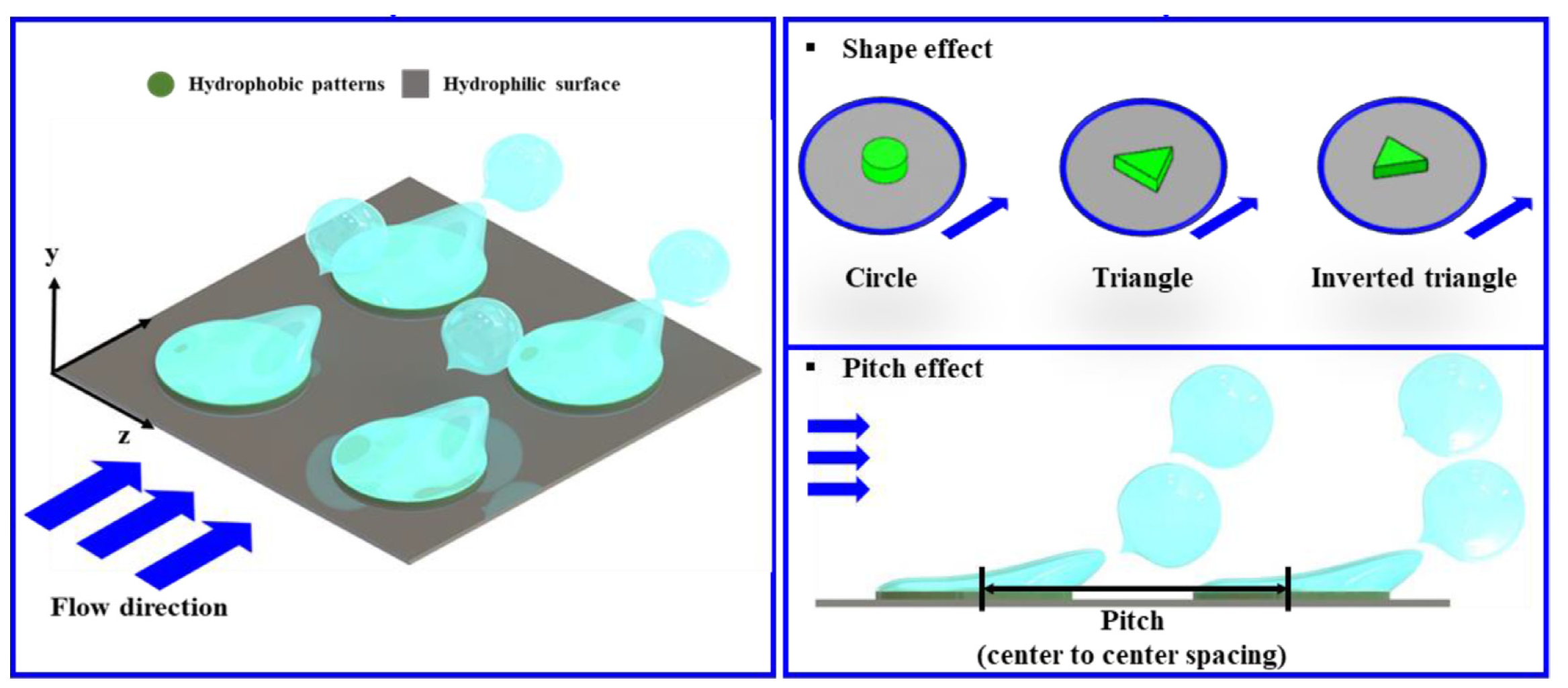
32] investigated the effect of the shape and spacing (pitch) of hydrophobic dots on biphillic (110° hydrophobic patterns on a 20° hydrophilic substrate) surfaces during flow boiling of deionized water in a 5 × 5 mm horizontal channel. Hydrophobic dots consisted of a 200 nm thick fluorooctyltrichlorosilane (FOTS) layer. Investigated shapes included triangle, inverted triangle, and circle shapes with spacings of 0.75 and 1 mm (see Figure 10).
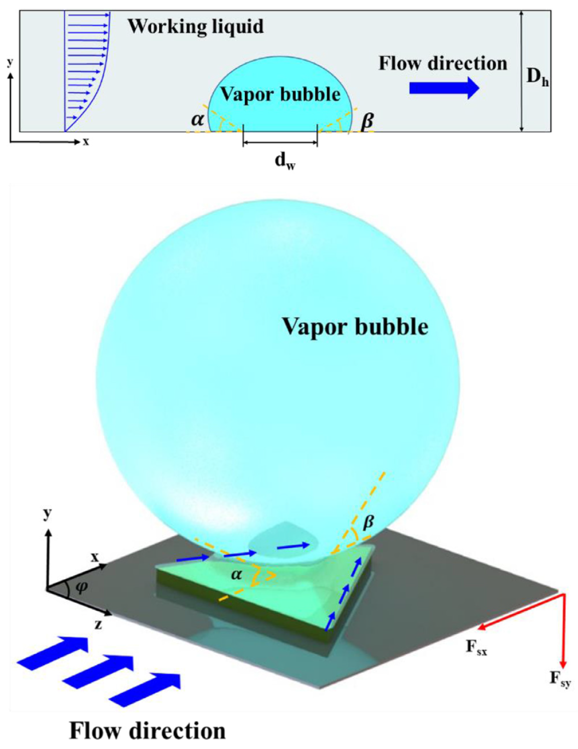
The authors noted that there should be favorable spacing between hydrophobic patterns as expressively close patterns can negatively impact each other (early bubble coalescence). Their findings demonstrated that CHF was increased on patterned surfaces (40% w.r.p.t. reference surface), but shape and spacing did not significantly affect CHF. Regarding HTC, it was superior for patterned surfaces. HTC increased with increasing spacing from 0.75 to 1 mm for a fixed shape. This was explained by an increasing bubble departure diameter for a decreasing spacing between patterns, which in turn also reduced bubble departure frequency. Furthermore, the triangle shape was superior, producing the smallest bubble diameter and the highest detachment frequency. So, some hydrophobic patterns seem to release vapor bubbles more efficiently. The relationship between surface tension forces of individual bubbles and hydrophobic-patterned shapes needed to be understood. This effect was linked to the bubble lift force using a force balance. If the surface tension force in the × direction ( F s x ), opposite to the fluid’s shear lift force, becomes relatively small, the bubble can slide along the heating surface. In contrast, when the surface tension force in the y direction ( F s y ), opposite to the buoyancy force, becomes small, the bubble forming on the hydrophobic pattern can lift off more easily. Critical parameters for estimating relative surface tension forces in × and y directions are the polar angle of hydrophobic patterns ( ψ ), the bubble dynamic contact angles (advancing α and receding β ), and the bubble contact line ( d w ). A schematic diagram is presented in Figure 11.
F s x and F s y could then be mathematically analyzed for each shape and then combined into a force ratio called the bubble lift force, F s y F s x . For circular, inverted triangle, and triangle hydrophobic-patterned arrays, the corresponding ratios were 0.06, 0.85, and 1.21. In conclusion, vapor bubbles can be removed more efficiently from the triangle-patterned surface as they are easily swept away by the flow (x direction) and evacuate more easily, resulting in smaller bubble sizes and higher frequency. The triangle with a spacing of 1mm was the optimal design investigated in the study.
Lin et al. [33] studied the effect of hydrophobic stripes perpendicular (1 mm thick, 1 mm spacing) and parallel (1.5 mm thick, 2mm spacing) to the flow direction on biphillic surfaces during the flow boiling of deionized water in a 5 mm × 0.5 mm (micro)channel. Patterns were made of simple coated Teflon. It was found that having patterned stripes perpendicular to the flow direction offers better heat transfer performance and reduces flow instability because bubbles are restricted from expanding in the axial direction because the contact line is pinned between the stripes. In this case, pressure drops are also reduced.
Kim et al. [34] examined effects on HTC and CHF of macrochannel flow boiling of subcooled deionized water on silicon substrates coated with sputtered 200 nm thick titanium (TiO2) or zinc oxide (ZnO) layers used as “smart” coatings. The term ”smart” relates to the ways in which these surfaces can transition from hydrophobic to hydrophilic based on their temperature. This means that the benefits of hydrophobicity at low heat fluxes (higher nucleation site density and earlier ONB) and hydrophilicity at high heat fluxes (delay of CHF) could be combined without extra external input. On these smart surfaces, contact angles decreased as temperature increased. The main benefit and goal of these coatings is thus improvement of HTC without degradation of CHF. The extra thermal resistance of the coating was deemed to be negligible. The authors found that at low mass flow rates, HTC increased. Still, the wettability transition temperature was not reached, resulting in a degradation of CHF compared to the untreated sample as the hydrophilic state was not reached. They observed a considerable increase in HTC at higher mass flow rates without decrease in CHF. The ZnO coating performed better than the TiO2 one. Furthermore, the authors investigated the hysteresis effect of wettability transition by gradually decreasing and then increasing the heat flux. Slight decreases in HTC were observed, but overall performance was still much better than the reference case.
Moiz et al. [35] sought to understand the bubble base growth mechanisms on hydrophobic surfaces under the influence of bulk flow inertia and compare them to hydrophilic surfaces in similar conditions at low heat fluxes. Specifically, they investigated microlayer formation under flow boiling bubbles on a hydrophobic surface with a contact angle of 90°. They used water and a 1 × 0.5 × 75 cm vertical test section, including a transparent ITO heater dedicated to studying single bubbles employing high-speed imaging for bubble dynamics and thin-film interferometry for microlayer dynamics and microlayer thickness measurement. In pool boiling, a microlayer is absent on hydrophobic surfaces because a vapor seed is always present on the surface, and contact line evaporation is the governing bubble growth process. It was found that the presence of a microlayer significantly impacts bubble dynamics and shape in flow boiling. Also, the evolution of the microlayer is different from that of hydrophilic surfaces due to the hydrodynamic movement of the contact line due to flow inertia. During the initial growth phase, the vapor bubble exhibits a strong microlayer. Depletion of the microlayer (growing of dry patch) on the hydrophobic surface started from the inside and was followed by first upstream and later downstream microlayer depletion. When the microlayer was fully depleted, the bubble changed shape and bent with the flow direction. From this point, there was only pure contact line evaporation remaining. Figure 12a emphasizes the different microlayer dynamics between hydrophilic and hydrophobic surfaces. The microlayer never fully depletes on the hydrophilic surface, and earlier bubble lift-off is promoted. Bubble base dynamics are significantly affected by surface wettability, mainly attributed to the size of the dry patch (actual bubble base). The size of the dry patch is also directly related to the experienced surface tension force in the flow direction as given by the equation of Klausner [36].
F S , f l o w = 1.25 d b σ π θ a d θ r e π 2 θ a d θ r e 2 sin θ a d + sin θ r e .
This equation shows proportionality between bubble base diameter d b and surface tension force in the flow direction. Forces are also indicated in Figure 12b. A larger dry patch is formed on hydrophobic surfaces, resulting in a higher surface tension force, essentially pinning the bubble to the surface. The hydrophilic surface has a much smaller dry patch, resulting in a low surface tension force that can easily reduce to zero for bubble lift-off.
Experimental results emphasized the need for a separate model for the hydrophobic surface in flow boiling, as it involves microlayer formation and depletion. There was a coupled effect of microlayer evaporation and hydrodynamic movement of the triple contact line. Also, no seed was left behind on the surface, opposite to pool boiling on similar hydrophobic surfaces.
Salmean et al. [37] investigated superbiphilic wettability patterning using chemicals and plasma etching for water flow boiling in rectangular silicon microgap channels with a width of 2 mm, a length of 22 mm, and a depth of 230 µm. The authors exploited contact line pinning on a range of geometries and orientations of superhydrophobic spots. Most interesting is that they also employed superhydrophilic cut-outs within the superhydrophobic spots, further enhancing their performance. Figure 13 shows the investigated hydrophobic spot geometries. Factor α denotes the fraction of the total area that was cut out.
When compared to homogeneous superhydrophobic and superhydrophilic surfaces, it was shown that their superbiphilic surfaces overall performed better in terms of both HTC and CHF and often by a large margin, thus negating the CHF/HTC compromise normally observed in homogeneous wettability surfaces. The ease of departure from bubbles from superhydrophobic spots depended on interactions between the local contact angle and bubble tilting due to hydrodynamic drag. Sweeping of bubbles from their nucleation sites was enhanced by controlling the bubble contact perimeter to shift the force balance in favor of departure. The desired strong contact line pinning was achieved by maximizing the biphilic wetting contrast. Contact line pinning effectively means that the spreading of vapor is limited by the hydrophobic spot edges by high capillary pressure, so there is constant contact line (CCL) growth of the bubble. As a result, rather than an expanding film, the vapor forms discrete bubbles only on superhydrophobic patches. Superhydrophilic cut-outs within the superhydrophobic dots are explained to lead to increased evaporation due to elongation of the vapor–liquid interface, and even trapping of liquid within the bubble may help to ameliorate dry-out phenomena further and ensure a strong supply of liquid to the boiling sites. The segregation of nucleation sites in all biphilic designs leads to significantly improved HTC (62% improvement with respect to the homogeneous hydrophilic surface through the best performing shape, namely the diamond with α = 0.5 ).
Symmetrical shapes (circle, square, diamond) showed increasing peak HTC when the cut-out fraction α was increased, which was thought to be because of more mobile bubbles since they were less prone to spreading and coalescence than in the case of no cut-out. Higher α leads to smaller bubbles in higher quantities. Also, trapped internal droplets help to maintain a lower temperature beneath the bubble, providing additional latent heat. It was also noted that increasing α corresponds with smaller pressure and temperature instabilities. Of the asymmetrical biphilic patterns (triangle), the upstream pointing triangles exhibited 21% higher peak HTCs with respect to downstream-pointing equivalents. It was also noted that increasing α causes peak HTC to increase in almost all cases. The contact line only unpins when the spreading force exceeds the restoring force on the surrounding hydrophilic area. This effectively translates to unpinning when the contact angle of the bubble reaches the receding contact angle of fluid on the hydrophilic substrate. Relation θ c = s i n 1 ( r w r b ) can be found for a circular bubble, as shown in Figure 14, but it extends to the general fact that the lowest contact angle, and thus the first point of unpinning, should be where the contact radius is minimum. Introducing a cut-out leads to the contact radius approaching a local minimum at the innermost point of the hydrophilic cut-out, thereby also hastening bubble unpinning.
Furthermore, the interaction of bubbles with the flow is also an important factor. The contact angle is expected to decrease at the downstream edge (bubble tilt) of the bubble as a result of flow impingement [36]. It was, therefore, deduced that the highest HTC would be encountered for those shapes whose minimum contact radius was pointing in the downstream direction, thus benefiting from the combination of contact radius and bubble tilt effects to encourage directional unpinning. This was confirmed by the data collected by the authors. The square-shaped hydrophobic dots outperformed the diamonds for α = 0 , the diamonds outperformed the circles at each examined α , and the upstream-pointing triangles outperformed their downstream-pointing equivalents at each examined α . Figure 15 illustrates the interactions between drag-induced and pinning-induced contact angle minimizations for the examined contact line geometries.
A contradiction to the previously stated theory was found as the square-shaped hydrophobic patches had a peak HTC similar to that of the upstream-pointing triangles, while it was expected to be a bit lower. A hypothesis was made that this could be the result of the upstream shape of the bubble face being broader on the square-pinned bubble and thus generating larger drag forces, resulting in greater net hydrodynamic force to encourage the departure of bubbles compared to the relatively streamlined upstream face of the triangular-pinned bubble.
It was noted that the proposed model indicates that bubble departure may be optimized on narrow biphilic stripes oriented perpendicularly to the flow direction. This was also the result of the experimental study of Kousalya et al. [38]. They noted that the best performance was observed when stripes were narrowed. It should be noted, however, that maintaining separation between adjacent nucleation sites can have benefits.
The study of Hsu et al. [32] found that downstream-pointing triangular patches exhibited superior performance over circular and upstream-pointing patches, which thus contradicts the conclusions of Salmean et al. [37]. The main difference between these studies is that Hsu used 5 × 5 mm millichannels, and Salmean used a microgap of 2 mm × 230 µm, making direct comparison more difficult. Millichannel boiling allows for significantly larger bubbles to form without confinement and flow reversal. Larger channels also allow substantially larger Reynolds numbers, and it can be that the turbulent flow in the study of Hsu et al. [32] interacts differently with the growing bubbles and acts to thin the thermal boundary layer. Furthermore, greater fluid velocities in the study of Hsu quadratically increase the hydrodynamic forces acting upon bubbles, diminishing the effects of surface tension forces in proportion. It can thus be that the surface tension forces in the study of Salmean et al. take a more significant role in bubble departure due to the proportionally much lower hydrodynamic forces compared to the study of Hsu.
Aboubakri et al. [39] used plasma polymerization to manufacture biphilic surfaces with hydrophobic dots. Flow boiling was performed using FC-72 in rectangular channels (15 mm wide, 1 mm deep, 51 mm long), showing up to 50% heat transfer performance enhancement compared to that of a uniform hydrophobic reference surface when the flow rate was set to 90 kg/m2s. This is a better reference choice, as it already provides higher heat transfer coefficients than a plain surface. The authors tested two samples with three equal-sized, distinct sections (inlet/middle/outlet). The first sample consisted of a hydrophobic section ( 110 ° ) followed by a biphilic section (500 µm dot size and 2 mm dot spacing) and a hydrophilic ( 55 ° ) section. The second sample consisted of a first biphilic section (500 µm dot size and 1.5 mm dot spacing) followed by the same biphilic section as the other sample, and then followed again by a hydrophilic section. It was found that Surface 2 slightly outperformed Surface 1 in the studied cases. During bubble visualization, it was noted that bubbles coalesced on the hydrophobic reference surface, leading to transitions from bubbly to slug flow. In contrast, biphilic surfaces did not result in slug flow as they were well dispersed due to the designed hydrophobic islands. It was reasoned that fluid velocity was higher in the remaining channel cross-section, resulting in higher shear force applied to the bubbles, which remain intact as long as the shear force is smaller than the surface tension force. Thus, it was postulated that the higher shear force results in the breakup of the bubbles on the biphilic surfaces and prevents effective coalescence of the bubbles.

5. Foams

Porous foams are another type of structure that can be used for boiling enhancement. The main traits of these foams are their low density, large surface area-to-volume ratio, and high bulk thermal conductivity when made out of a fitting material. The mixing of the flow is also enhanced due to the increased ratio of actual flow path length with respect to the straight distance between the inlet and the outlet. This parameter is also called the tortuosity of the foam. The ratio of void space to the total volume occupied by the foam is called porosity. Another parameter often used to describe foams is the number of pores per inch (PPI, a lower PPI refers to larger pores). A relative insensitivity of foam-filled channel heat transfer to the thermal conductivity of the fluid also makes porous foams an attractive method for heat transfer with low conductivity fluids, such as dielectric fluids used in, e.g., electronics cooling. Figure 16 shows an example of metal foams.
Kim et al. [41] performed flow boiling experiments using water and mainly FC-72 in a 10 mm wide × 37 mm long and 7 mm high channel filled with copper foams with 10 and 20 PPI and porosity of 92 and 95%. It was reported that an increase in the mass flux from 20 kg/m2s to 48 kg/m2s enhanced HTC by as much as 15% with the best sample, but a further increase up to 72 kg/m2s again removed any enhancement. In conclusion, the foam with a larger pore size (10 PPI) and highest porosity (95%) was shown to have better heat transfer characteristics given an approximate increase in HTC of 30–40%. As an explanation, it was argued that higher porosity and large pore size make it easier for the vapor to escape from the wall, especially at high heat fluxes, where more vapor needs to flow through the foam (higher vapor quality).
Lu et al. [42] performed a numerical and experimental analysis of flow boiling of R134a in horizontal 26 mm diameter metal foam tubes. In contrast to the findings of Kim et al. [41], their numerical predictions found that decreasing pore size, increasing pore density (PPI), and decreasing the degree of overall porosity resulted in significant overall heat transfer improvement. This was explained by reasoning that smaller cell sizes provide more overall surface areas and more active boiling sites. Furthermore, smaller cells can enhance flow mixing and break up any large bubbles, thereby increasing heat transfer coefficient. Also, the effect of porosity was examined, showing overall heat transfer enhancement by reducing the degree of porosity (from 95 to 85%). This was reasoned to be the case because decrease in porosity enhances conduction through the then more present solid structure, improving the overall heat transfer.
Pranoto et al. [43] used graphite porous foams with high thermal conductivity for flow boiling FC-72. Two different foams were used. The first one had a porosity of 61% with an average pore size of 0.35 mm, and the second one had a porosity of 72% with an average pore size of 0.65 mm. Important to note is that their foams did not occupy the entire channel area but also left a free gap on top. The effect of this gap was also tested for gaps of 6, 4, and 2 mm high. This means that the fluid flowed mainly through the gaps, and the amount of flow through the foams can be considered negligible. Experimental results showed that the imposed gap, mass flux, and foam properties affected flow boiling performance. A higher gap height increased performance since a smaller gap tends to cause more confinement for the bubbles compared to the larger gaps. This bubble confinement can reduce bubble departure frequency and vapor layer formation, decreasing boiling performance. From the investigated foam structures, the foam with the lowest porosity (61%) was found to have the best performance because of a larger bubble departure frequency and larger nucleation site density, confirmed by high-speed visualization. HTC was increased up to 250% compared to a smooth reference surface. An explanation was given: the lower porosity foam has higher effective thermal conductivity. It was also shown that the 61% porosity foam, having an average pore diameter about half that of the 72% foam, had a much larger surface area-to-volume ratio, leading to more active nucleation sites.
It can thus be understood that trying to model two-phase flow in porous foams is extra difficult due to the geometrical and fluid–vapor motion complexity. Regarding this, Li et al. [44] investigated the flow boiling of water and FC-72 in an aluminum foam, numerically (only water) and experimentally. The authors also investigated the effect of temperature hysteresis in heating and cooling cycles, which is caused by contact angle hysteresis that is partly responsible for phase hysteresis. The authors found that hysteresis only occurred for water and was absent for FC-72. Using the finite volume method, they performed numerical simulations for single- and two-phase heat transfer. Reasonable agreements were obtained between numerical and experimental results. This demonstrates the capability of the developed codes to simulate single- and two-phase heat transfer in porous media.
Madani et al. [45] performed an experimental study of flow boiling n-pentane in a foam-filled channel. A copper foam of 36 PPI and 97% porosity was used. Results showed an enhancement in heat transfer coefficient by a factor of two to four for low vapor quality compared to a plain tube heat transfer coefficient, calculated from Gungor–Winterton correlation [46]. This factor decreases with increasing vapor quality. According to Gungor–Winterton correlation, the authors also identified an inversion point where the metallic foam reduces heat transfer compared to a plain channel. HTC decreased with heat flux, vapor quality, and wall superheat, with a maximum value at the onset of nucleate boiling. When nucleation intensified, a vapor layer began to form on the wall due to bubble coalescence and the resistance of the foam to bubble movement. The wall superheats for the onset of nucleation were 10 times smaller than the predicted correlation values.

6. Hybrid Structures

It is apparent that many created textures possess different length scales within the texture, regardless of whether they are intentionally made or not. This section discusses some recently deliberately created hybrid scale structures. For completeness and to avoid confusion, for example, the textures produced by Lim et al. [13] and previously described in Section 2.2 are also hybrid structures because of LIPSS being inherent to the employed manufacturing technique.
Huang et al. [47] created a three-layer hybrid surface structure pattern ranging from a submillimeter to a nanoscale size with a specific application case for water flow boiling in fusion reactors impacting material and operating condition choices. The channel dimensions used were 10 mm × 20 mm × 100 mm, and water pressure was set at 0.5 MPa, corresponding to a saturation temperature of 425 K. The authors used a downward-facing heated surface orientation corresponding to the cooling system’s most unfavorable working conditions. The submillimeter structure was created with a copper wire mesh (wire diameter of 10–100 µm and aperture width of 50–600 µm), joined to a CuCrZr alloy base substrate by a brazing filler, which was a powder mixture including micro/nanoparticles of Ag, Cu, and Ti. The first pattern layer was thus the submillimeter scale cavities formed by wire mesh apertures and the substrate. The second layer consisted of a microscale irregular concave and convex morphologies on top of the first layer due to heterogeneous melting and solidification of the filler powder. Lastly, the third layer consisted of nanoparticles or nanoscale pillars on top of the second layer. Figure 17 shows a schematic of the three-layer configuration.
The authors selected four types of wire mesh (aperture × wire diameter: (1) 590 × 100 µm, (2) 250 × 90 µm, (3) 125 × 60 µm, (4) 58 × 40 µm) to investigate. When changing the wire mesh, different combined structures appeared. The authors postulated that controllability and reproducibility of the texturing technique can be ensured by controlling wire mesh specifications and the thickness of the brazing filler material used. The scale of the microporous texture (second layer) was observed to be around 20–40 µm. The scale of the third layer textures, consisting of pillars or particles, was measured to be around 100 nm. Contact angle measurements were performed to assess the effect of the structures on wettability. For all four cases, the contact angle was around 110°, thus being hydrophobic. In all textured cases, there was significant improvement in HTC (2–3 times) and CHF (2 times) compared to the plain base substrate. Mesh 4 performed the best at higher heat fluxes, and Mesh 3 performed the best at lower heat fluxes. Pressure drops for textured surfaces were found to have a peak increase of less than 12% compared to plain baseline. Enhancement in HTC was found to increase with flow velocity from 1 m/s to 3 m/s to 5 m/s.
Upot et al. [48] studied the effect of etching micro/nanostructures on commercial internally finned aluminum tubes (herringbone crosshatch clad Grade 7072) as well as etching an unfinned tube for comparison for flow boiling of R-515B (a low GWP replacement refrigerant for R-134a). Texturing was performed in a scalable way by chemical etching using hydrochloric acid. Etched surfaces displayed micro and nanoscale cavities with an average structure height of 5 µm compared to a fin height of approximately 250 µm. Enhancements were found to be lower at low vapor qualities and higher at high vapor qualities due to the varying effects of nucleate and convective boiling. The authors found that, at high inlet vapor qualities, in annular flow (convective boiling), the etched sample had a more stable and thinner liquid film due to capillary action, delaying dry-out and significantly enhancing HTC (peak 172%). A lower film thickness enables more efficient heat transfer because of lower conduction resistance and enhanced evaporation. Studying the effects of mass and heat flux variation, the authors concluded that the finned untreated tube had more convective contributions, while the finned treated tube showed increased nucleate boiling contribution. Pressure drops were also studied. The finned treated surface displayed an increased pressure drop (average 20%) at the same conditions compared to the untreated finned surface. This was attributed to increased nucleation, enhanced evaporation, and increased roughness of the finned-treated aluminum surface. The finned (treated and untreated) samples were further compared to a non-finned tube following the same etching procedure to complete the analysis. Some of the presented results are shown in Figure 18.
The authors concluded that the heat transfer coefficient is maximum for the finned etched sample as it includes the most nucleation sites, and pressure drop is minimum for the etched unfinned sample while still showing high HTC enhancement. Since the etched-unfinned tube has better HTC and lower pressure drop than the finned untreated sample, it might be a valid replacement, reducing costs otherwise associated with extrusion/welding/drawing equipment used in finned tubing manufacturing.
Liu et al. [49] produced a silicon wafer surface combining both ZnO nanorods and micro pin fins (PF + NR), comparing it to a nanorod (NR) only, a micro pin fin (PF) only and a smooth (S) reference surface and noted considerable improvements in their combined sample over the others. The maximum HTC was improved by 63%, 76% and 158%, and CHF was improved by 31%, 33% and 74%, respectively. ONB was also reduced. Cooperation of the different scales was attributed to the nanorods providing abundant nucleation sites and reducing ONB and the micro pin fins improving wickability and suppressing lateral coalescence of large bubbles at high heat fluxes. The dimensions of the micro pin fins were 30 × 30 × 30 × 60 µm (length, width, gap, height), and clusters of nanorods were attached to the top, base, and sides of the micro pin fins. The test section area was 5 × 15 mm, and the working fluid was FC-72. The authors noted good repeatability and durability of the test surface over ten consecutive boiling tests and one week of exposure to air. Boiling curves are presented in Figure 19 for different flow velocities and a subcooling of 35 degrees. Notably, for PF + NR, next to the enhanced CHF, the wall superheat was only 7 °C at a velocity of U = 1 m/s, which is drastically lower than the other surfaces.
Furthermore, it was noted that the curves of the surfaces with nanoscale features almost overlap with each other in the nucleate region for every tested velocity, showing weakened effects of velocity because of smaller bubbles, which are easier to depart. Figure 20 shows the resulting heat transfer coefficients.
It was noted that, by superimposing the nanostructure to the microstructure, the heat transfer coefficient was increased by about 20% in addition to the microstructure only. This was explained by reasoning that, for a sample with only nanorods, a large amount of the extended surface area is covered by the thermal boundary layer and thus not fully utilized. For the hierarchical surfaces, the larger dimension of the pin fins increases the utilization of the nanostructure, and since they are attached to the top base and sides of the fins, the surface area is expanded, and the nucleation site density is increased. The CHF enhancement was also clearly the largest for the hierarchical surface. The CHF enhancement ratio decreased when velocity increased since convective effects started to dominate over nucleate effects. At higher velocities, bubbles depart at smaller diameters and with higher frequency, limiting the role of surface structure in regulating bubble behavior. It was also noted that the wickability, often ascribed as a critical factor for CHF determination, was not deemed the main reason for improvement in this case, as PF and PF+NR samples have almost identical wickability. Instead, the regulation of bubble behavior by the surface structure was deemed the main reason. The NR surface is limited in CHF by insufficient wicking. Since the bubbles are generated on the same plane due to the small structure size, vigorous lateral coalescence can occur. For the PF sample, wickability was greatly improved, and lateral coalescence was suppressed as bubbles were distributed on top and bottom of the fins and restricted from lateral expansion, promoting departure as the surface energy during coalescence was partially converted into kinetic energy. In conclusion, it was found that, in the studied case, the combination of nanostructure and microstructure features increases heat transfer area, maintains high wickability, and realizes a more ideal bubble behavior.

7. Nucleation Site Interaction

While the previous sections were mostly dedicated to the created surface geometries, this section looks a bit deeper into the interaction between different nucleation sites as the departed bubbles can still influence other bubbles and nucleation sites, e.g., based on their subsequent trajectory.
The first type of nucleation site interaction can be the coalescence of neighboring bubbles. Bubble coalescence can happen both vertically and horizontally. In general, horizontal coalescence is expected more if the surface is hydrophobic, while vertical coalescence is often the more likely case with hydrophilic surfaces. Horizontal coalescence directly influences boiling surface heat transfer because of the increased contact line of the merged bubble and the potential effect on the neighboring nucleation sites. Vertical coalescence can mainly affect heat transfer from the flow path or pattern perspective.
For horizontal coalescence on the boiling surface, there should be a critical coalescence distance. When the distance between nucleation sites exceeds this critical distance, bubbles do not coalesce on the surface. This critical coalescence distance increases with increasing contact angle (bubble diameters also increase), meaning hydrophobic surfaces need a larger spacing of nucleation sites to prevent coalescence [50].
Baltis et al. [51] studied the interaction of nucleation sites parallel and perpendicular to the flow direction during saturated upward flow boiling of demineralized water using distributed heated sites of 1 × 1 mm2. Depending on the imposed mass flow rate, flow direction, and heat fluxes to bubble generation sites, the authors showed that nucleation sites interact at any nucleation site distance. Two major trends were observed. The first trend was that additional convection from a non-boiling upstream bubble generation site (U-BG) increased the nucleation frequency and bubble detachment diameter of the downstream bubble generation site (D-BG). This influence diminished for increasing spacing (S) between the generation sites and for increasing nucleation frequency at D-BG and increased for increasing flow rate. This spacing is often represented as a non-dimensional form, S / D b , related to bubble departure diameter. The second trend was observed after the onset of boiling on U-BG. Bubbles that nucleated at U-BG and passed near D-BG led to a negative inhibiting effect on bubble nucleation at D-BG. This inhibitive effect diminishes with increasing nucleation frequency at D-BG. Hydrodynamic interaction has a significant effect on the number of active nucleation sites and bubble size at detachment. A conclusion was also drawn with respect to the influence of nucleation sites perpendicular to the flow direction in upward flow boiling, namely that there are no nucleation site interactions when the S / D b ratio is 1.33 or larger. It is, however, expected that for S / D b smaller than one, bubbles influence each other hydrodynamically and may coalesce.
The first trend can also be seen in Figure 21. As the power to U-BG increases for a fixed power to an active D-BG site with an initial departure frequency, so does the bubble nucleation frequency at D-BG. When the power to U-BG is large enough to initiate bubble nucleation, f n u c at D-BG starts decreasing as the frequency of U-BG itself increases. The effect diminishes for increased site spacing, as was tested for S = 2 mm to S = 10 mm. For the used flow rate of 0.45 m/s and initial D-BG frequency of 15 Hz, at S = 2 mm, the frequency at D-BG even doubled before the onset of bubbles at U-BG, which reduced it again to half the initial value.
Also, bubble departure diameter showed considerable increase at constant power D-BG for increasing power to U-BG. Increasing site spacing also diminished the effect here. For S = 2 mm, D b increased by around 20% compared to approximately 2% for S = 10 mm for a flow rate of 0.45 m/s and the D-BG initial frequency of 15 Hz.
Additional experiments were performed at a higher initial nucleation frequency at D-BG. The trends were similar to what was observed at a lower initial frequency. Relative effects on frequency and diameter were lesser. Effects were compared between D-BG initial frequencies of 15 Hz and 40 Hz, where the 40 Hz case showed only around half the relative effects that were observed at 15 Hz. Lastly, the effect of flow rate was introduced by increasing flow velocity from 0.45 m/s to 0.85 m/s. When bulk velocity is higher, the bubbles leave faster and with a smaller diameter. Observed trends were similar to what was observed before. At higher flow rates, the effects were also notable on larger site spacings, and the impact on the closest spacings was more severe, in the case of S = 2 mm, even leading to near-complete deactivation of D-BG after the onset of bubbles on U-BG. The first trend of increasing f D - B G and D b was explained by the increased convective heat supplied by U-BG and its thermal boundary layer development. The authors reasoned that the added heat from U-BG becomes partially mixed into the bulk liquid flow, and its contribution rapidly decreases with increasing site spacing. The increase in bubble frequency at D-BG, diminishing for increasing initial frequency at D-BG, was explained by the added convective heat from U-BG being partly consumed and diverted away by nucleating bubbles from D-BG. Also, the relative increases in nucleation frequency at higher flow rates were explained by the heat generated at U-BG reaching D-BG faster, offering less time to diffuse heat into the bulk liquid. The conclusion here was that the largest increases in D-BG frequency could be expected for high flow rates and low initial D-BG frequencies, referring to the onset of nucleate boiling (ONB). The increase in D b was also explained by the added convective heat at U-BG, as this leads to an increase in the thickness and mean temperature of the thermal boundary layer at D-BG, which allows for the bubbles at D-BG to grow larger before detachment.
The second trend of bubble frequency of D-BG decreasing when U-BG starts creating vapor bubbles of its own was explained by three combined reasons. First, the added convective heat that D-BG was receiving from U-BG suddenly dropped because the bubbles at U-BG were consuming this heat now also for their own growth. Second, when bubbles from U-BG moved towards and passed by D-BG, they scavenged away heat in the thermal boundary layer of D-BG for additional evaporation, which increased the size of this passing bubble. This resulted in a lower mean temperature of the boundary layer at D-BG. For this effect to be significant, the bubble must travel close to the thermal boundary layer (boundary layer thickness was 0.1 mm in the reported experiments). This effect inhibits the nucleation of new bubbles at D-BG. Finally, when a bubble passed by D-BG, its low-pressure wake enhanced mixing and direct hot liquid away from the surface. Convective heat transfer from D-BG was enhanced.
Of course, the inhibitive effect of passing bubbles by any D-BG is observed at any spacing. This also mainly depends on the flow direction and, thus, the bubble path. In vertical upward flow, as was studied by the authors, the lift force on isolated bubbles acted in the direction of the wall, as shown by [52] for Eötvös number <4 corresponding to D b < 5 mm for water, explaining why bubbles were observed to move towards the wall as they flowed upward. So, as this resulted in bubbles traveling near D-BG, inhibition of bubble nucleation can occur there. If one were to look at a downward flow configuration, this inhibiting effect would be expected to play a smaller role since the bubbles would be forced toward the center of the flow instead. However, one needs to understand that even though an upward flow configuration may lead to less active nucleation sites because of bubble interference, bubbles are smaller in the downflow compared to the upflow since, in the upflow, they travel closer to the heated wall. The authors [51] also concluded that the heat transfer per active site was significantly larger for the upflow.
In conclusion, Baltis et al. [51] postulated that to predict the site-to-site interaction at other site distances and for other liquid mass flow rates than examined above, the boundary layer development from the upstream site must be predicted, as well as trajectories of bubbles originating from all upstream sites. So, when entering the thermal boundary layer next to another nucleation site, bubbles extract heat, and interaction occurs. When creating enhanced textured surfaces, optimal design should include bubble interaction effects for the desired operating conditions.

8. Concluding Remarks

It is thus very apparent that in paving the path towards increasingly efficient heat extraction, the boiling surface still holds a vast amount of potential that needs to be extracted in a fitting way. This is not surprising, as the basic mechanisms of boiling are taking place on a fundamental scale, directly at the surface level.
This paper reviews the existing, more recent literature concerning the enhancement of flow boiling heat transfer in channels by surface modifications. Different manufacturing techniques and texture properties are discussed and linked to the flow boiling heat transfer performance in terms of wall temperatures, HTC, and CHF. Some key observations can be listed as follows:
  • As is the case in single phase convection, “conventional” macroscale textures like fins effectively improve HTC and CHF by increasing the overall heat transfer area and improving mixing. However, the actual nucleation process takes place on a much smaller scale, so the improvements of the fundamental boiling mechanisms need to be explored by examining micro- and nanoscale textures.
  • Explored microscale textures include micro-fins, microgrooves, microcavities, chemical etching, porous coatings, chemical coatings, and foams. A multitude of manufacturing techniques can be employed, all with their own distinctive characteristics and inherent effects. In all cases, key objectives are increased nucleation site density and enhanced bubble dynamics, allowing for an increase in HTC and CHF. Further studies are needed to be able to conclusively optimize the actual texture parameters like the size, shape, spacing, depth, inclination, and pattern of fins, grooves, and cavities, the composition, particle size, and thickness of porous coatings, the hydrophobic spot shape, size, composition and pattern of chemical coatings, and the composition, porosity, and pore size range of foams.
  • Nanoscale textures can mainly enhance capillary wicking to nucleation sites. Still, usually, they do not result in drastic enhancement on their own because of a lack of fixed nucleation sites without the microscale textures. Non-intrinsic nanoscale textures (e.g., carbon nanotubes) are also expected to be first in line in experiencing degradation effects after prolonged boiling.
  • Hybrid structures knowingly employ the benefits of different scales to increase flow boiling heat transfer performance further. Specific manufacturing techniques inherently create multiscale hierarchical features, such as laser texturing microtextures, resulting in a superposition of periodic sub-micron ripples (LIPSS) due to light–matter interaction. Sometimes, the extra effects related to the manufacturing process can be easily overlooked, but one should be aware of their possible existence when drawing conclusions.
  • The absence of general predictive design tools for different channel configurations/materials, different fluids, and different operating conditions like the flow rate and subcooling is hindering the implementation of enhanced surfaces in mainstream applications. A universal understanding of the basic mechanisms is needed to provide the necessary tools, as a surface would only be optimal for a specific application case.
  • It is essential to note that the presented enhancement percentages in the majority of studies are related to the specific author’s reference surface and that extremely high enhancements may result from comparison to a deliberately worsened (e.g., polished) plain surface to increase contrast. Therefore, one should consider the absolute HTC and CHF values when comparing textured surfaces. Plain surfaces can be highly random in terms of performance depending on the material/treatment/manufacturer, and a better, more stable reference is therefore advised.
  • Something that is often disregarded in discussions is the effects of surface degradation due to prolonged boiling. It is important to consider these effects as the specified performance may not be long lasting and should be thoroughly and systematically characterized before possible commercial application to ensure repeatability and reliability of system performance. Degradation effects include:
    • Particulate fouling due to impure liquids or chemical fouling due to fluid degradation, leading to nucleation site deactivation or new nucleation site creation.
    • Non-intrinsic surface features are prone to physical degradation. Especially deposited coatings are known to have a limited lifetime because of the possibility of detachment from the substrate.
    • The used manufacturing technique may alter the surface chemistry, leading to time-dependent effects related to environmental exposure.
  • Attention should also be paid to bubble trajectories after detachment, as there may be interaction with downstream nucleation sites.
  • One more parameter that is not often explored is the effect of gravity on the boiling process. As a heated surface is rotated 360 degrees, the resulting flow pattern is drastically different and should be considered for the best surface texture choice.
While this review provides insight into existing knowledge and achievements in the field, it also underlines the need for continued exploration, experimentation, and innovation. Future strategies should address more practical implementation challenges, scale manufacturing capabilities, and explore novel techniques that boost performance and ensure cost effectiveness and durability for commercial implementation. Ultimately, a new class of highly efficient and sustainable thermal management solutions can be achieved only through collaborative efforts, interdisciplinary approaches, and the continued pushing of boundaries.

Author Contributions

Conceptualization, F.M.; investigation, F.M.; writing— original draft preparation, F.M.; writing—review and editing, F.M., S.C. and M.R.V.; supervision, M.R.V.; funding acquisition, M.R.V. All authors have read and agreed to the published version of the manuscript.

Funding

The authors acknowledge the financial support of Fonds Wetenschappelijk Onderzoek—Vlaanderen (FWO) through a personal SB fellowship (1S62224N), FWO Weave project G066722N and ESA contract No. 4000135205/21/NL/GLC/my.

Conflicts of Interest

The authors declare no conflict of interest.

Abbreviations

The following abbreviations are used in this manuscript:
ONBOnset of Nucleate Boiling
HTCHeat Transfer Coefficient
CHFCritical Heat Flux
GWPGlobal Warming Potential
PPFPiranha Pin Fin
LIPSSLaser Induced Periodic Surface Structures
MGCC-LFMicro-Groove covered Clustered Cavity by Low laser Fluence
MGCC-HFMicro-Groove covered Clustered Cavity by High laser Fluence
MEKMethyl–Ethyl–Keytone
BPMBi-Porous Minichannels
PSMPlanar Surface Minichannels
FOTSFluorooctyltrichlorosilane
ITOIndium–Tin–Oxide
CCLConstant Contact Line
PPIPores Per Inch
PFPin Fin
NRNanorod
U-BGUpstream bubble generation site
D-BGDownstream bubble generation site

References

  1. Liang, G.; Mudawar, I. Review of pool boiling enhancement by surface modification. Int. J. Heat Mass Transf. 2019, 128, 892–933. [Google Scholar] [CrossRef]
  2. Kim, D.E.; Yu, D.I.; Jerng, D.W.; Kim, M.H.; Ahn, H.S. Review of boiling heat transfer enhancement on micro/nanostructured surfaces. Exp. Therm. Fluid Sci. 2015, 66, 173–196. [Google Scholar] [CrossRef]
  3. Hasan, M.I. Investigation of flow and heat transfer characteristics in micro pin fin heat sink with nanofluid. Appl. Therm. Eng. 2014, 63, 598–607. [Google Scholar] [CrossRef]
  4. Ma, A.; Wei, J.; Yuan, M.; Fang, J. Enhanced flow boiling heat transfer of FC-72 on micro-pin-finned surfaces. Int. J. Heat Mass Transf. 2009, 52, 2925–2931. [Google Scholar] [CrossRef]
  5. Wei, J.; Zhao, J.; Yuan, M.; Xue, Y. Boiling heat transfer enhancement by using micro-pin-finned surface for electronics cooling. Microgravity Sci. Technol. 2009, 21, 159–173. [Google Scholar] [CrossRef]
  6. Wei, J.J.; Honda, H. Effects of fin geometry on boiling heat transfer from silicon chips with micro-pin-fins immersed in FC-72. Int. J. Heat Mass Transf. 2003, 46, 4059–4070. [Google Scholar] [CrossRef]
  7. Guo, D.; Wei, J.J.; Zhang, Y.H. Enhanced flow boiling heat transfer with jet impingement on micro-pin-finned surfaces. Appl. Therm. Eng. 2011, 31, 2042–2051. [Google Scholar] [CrossRef]
  8. Krishnamurthy, S.; Peles, Y. Flow boiling heat transfer on micro pin fins entrenched in a microchannel. J. Heat Transf. 2010, 132, 1–10. [Google Scholar] [CrossRef]
  9. Tullius, J.F.; Tullius, T.K.; Bayazitoglu, Y. Optimization of short micro pin fins in minichannels. Int. J. Heat Mass Transf. 2012, 55, 3921–3932. [Google Scholar] [CrossRef]
  10. Wan, W.; Deng, D.; Huang, Q.; Zeng, T.; Huang, Y. Experimental study and optimization of pin fin shapes in flow boiling of micro pin fin heat sinks. Appl. Therm. Eng. 2017, 114, 436–449. [Google Scholar] [CrossRef]
  11. Woodcock, C.; Yu, X.; Plawsky, J.; Peles, Y. Piranha Pin Fin (PPF)—Advanced flow boiling microstructures with low surface tension dielectric fluids. Int. J. Heat Mass Transf. 2015, 90, 591–604. [Google Scholar] [CrossRef]
  12. Sommers, A.D.; Yerkes, K.L. Using micro-structural surface features to enhance the convective flow boiling heat transfer of R-134a on aluminum. Int. J. Heat Mass Transf. 2013, 64, 1053–1063. [Google Scholar] [CrossRef]
  13. Lim, K.; Lee, K.; Ki, H.; Lee, J. Enhancement of flow boiling heat transfer by laser-induced periodic surface structures using femtosecond laser. Int. J. Heat Mass Transf. 2022, 196, 123229. [Google Scholar] [CrossRef]
  14. Belyaev, A.V.; Dedov, A.V.; Sidel’nikov, N.E.; Jiang, P.; Varava, A.N.; Xu, R. Flow Boiling Heat Transfer Intensification Due to Inner Surface Modification in Circular Mini-Channel. Water 2022, 14, 4054. [Google Scholar] [CrossRef]
  15. Das, A.K.; Das, P.K.; Saha, P. Some investigations on the enhancement of boiling heat transfer from planer surface embedded with continuous open tunnels. Exp. Therm. Fluid Sci. 2010, 34, 1422–1431. [Google Scholar] [CrossRef]
  16. Moreira, D.C.; Nascimento, V.S.; Ribatski, G.; Kandlikar, S.G. Combining liquid inertia and evaporation momentum forces to achieve flow boiling inversion and performance enhancement in asymmetric Dual V-groove microchannels. Int. J. Heat Mass Transf. 2022, 194, 123009. [Google Scholar] [CrossRef]
  17. Kandlikar, S.G. Controlling bubble motion over heated surface through evaporation momentum force to enhance pool boiling heat transfer. Appl. Phys. Lett. 2013, 102, 051611. [Google Scholar] [CrossRef]
  18. Upot, N.V.; Mahvi, A.; Rabbi, K.F.; Li, J.; Jacobi, A.M.; Miljkovic, N. Scalable and Resilient Etched Metallic Micro- And Nanostructured Surfaces for Enhanced Flow Boiling. ACS Appl. Nano Mater. 2021, 4, 6648–6658. [Google Scholar] [CrossRef]
  19. Rainey, K.N.; Li, G.; You, S.M. Flow boiling heat transfer from plain and microporous coated surfaces in subcooled FC-72. J. Heat Transf. 2001, 123, 918–925. [Google Scholar] [CrossRef]
  20. Ammerman, C.N.; You, S.M. Enhancing small-channel convective boiling performance using a microporous surface coating. J. Heat Transf. 2001, 123, 976–983. [Google Scholar] [CrossRef]
  21. Sun, Y.; Zhang, L.; Xu, H.; Zhong, X. Flow boiling enhancement of FC-72 from microporous surfaces in minichannels. Exp. Therm. Fluid Sci. 2011, 35, 1418–1426. [Google Scholar] [CrossRef]
  22. Poniewski, M.E.; Thome, J.R. Nucleate Boiling on Micro-Structured Surfaces; Heat Transfer Research, Inc. (HTRI): Navasota, TX, USA, 2008. [Google Scholar]
  23. Lee, M.; Cheung, L.S.L.; Lee, Y.K.; Zohar, Y. Height effect on nucleation-site activity and size-dependent bubble dynamics in microchannel convective boiling. J. Micromech. Microeng. 2005, 15, 2121–2129. [Google Scholar] [CrossRef]
  24. Chen, C.A.; Chang, W.R.; Li, K.W.; Lie, Y.M.; Lin, T.F. Subcooled flow boiling heat transfer of R-407C and associated bubble characteristics in a narrow annular duct. Int. J. Heat Mass Transf. 2009, 52, 3147–3158. [Google Scholar] [CrossRef]
  25. Bai, P.; Tang, T.; Tang, B. Enhanced flow boiling in parallel microchannels with metallic porous coating. Appl. Therm. Eng. 2013, 58, 291–297. [Google Scholar] [CrossRef]
  26. Wang, C.; Su, G.; Akinsulire, O.; Zhang, L.; Rahman, M.M.; Bucci, M. Investigation of Critical Heat Flux Enhancement on Nanoengineered Surfaces in Pressurized Subcooled Flow Boiling using Infrared Thermometry. Heat Transf. Eng. 2023. [Google Scholar] [CrossRef]
  27. Tetreault-Friend, M.; Azizian, R.; Bucci, M.; McKrell, T.; Buongiorno, J.; Rubner, M.; Cohen, R. Critical heat flux maxima resulting from the controlled morphology of nanoporous hydrophilic surface layers. Appl. Phys. Lett. 2016, 108, 243102. [Google Scholar] [CrossRef]
  28. Rahman, M.M.; Ölçeroglu, E.; McCarthy, M. Role of wickability on the critical heat flux of structured superhydrophilic surfaces. Langmuir 2014, 30, 11225–11234. [Google Scholar] [CrossRef] [PubMed]
  29. Hsu, Y. On the Size Range of Active Nucleation Cavities on a Heating Surface. J. Heat Transf. 1962, 84, 207–213. [Google Scholar] [CrossRef]
  30. He, B.; Luo, X.; Yu, F.; Li, T.; Wang, L.; Zhou, J.; Fan, Y. Effects of inlet subcooling on the flow boiling heat transfer performance of bi-porous mini-channels. Appl. Therm. Eng. 2023, 229, 120577. [Google Scholar] [CrossRef]
  31. Tan, B.; Yang, C.; Cai, J.; Gong, Z.; Deng, R. Experimental and theoretical investigation on the effect of surface porosity on the nucleate flow boiling heat transfer. Prog. Nucl. Energy 2022, 154, 104471. [Google Scholar] [CrossRef]
  32. Hsu, W.T.; Lee, D.; Lee, N.; Yun, M.; Cho, H.H. Enhancement of flow boiling heat transfer using heterogeneous wettability patterned surfaces with varying inter-spacing. Int. J. Heat Mass Transf. 2021, 164, 120596. [Google Scholar] [CrossRef]
  33. Lin, Y.; Luo, Y.; Li, J.; Li, W. Heat transfer, pressure drop and flow patterns of flow boiling on heterogeneous wetting surface in a vertical narrow microchannel. Int. J. Heat Mass Transf. 2021, 172, 121158. [Google Scholar] [CrossRef]
  34. Kim, J.M.; Kang, S.H.; Yu, D.I.; Park, H.S.; Moriyama, K.; Kim, M.H. Smart surface in flow boiling: Spontaneous change of wettability. Int. J. Heat Mass Transf. 2017, 105, 147–156. [Google Scholar] [CrossRef]
  35. Moiz, M.; Vadlamudi, S.R.G.; Srivastava, A. Experiments to understand bubble base growth mechanism(s) on hydrophobic surfaces under the influence of bulk flow inertia during nucleate boiling regime. Int. Commun. Heat Mass Transf. 2023, 141. [Google Scholar] [CrossRef]
  36. Klausner, J.F.; Mei, R.; BERNHARDt, D.M.; ZENGt, L.Z. Vapor bubble departure in forced convection boiling. Int. J. Heat Mass Transfer. 1993, 36, 651–662. [Google Scholar] [CrossRef]
  37. Salmean, C.; Qiu, H. Flow Boiling Heat Transfer Enhancement Using Tuned Geometrical Contact-Line Pinning. ACS Appl. Mater. Interfaces 2023, 15, 23844–23859. [Google Scholar] [CrossRef] [PubMed]
  38. Kousalya, A.S.; Singh, K.P.; Fisher, T.S. Heterogeneous wetting surfaces with graphitic petal-decorated carbon nanotubes for enhanced flow boiling. Int. J. Heat Mass Transf. 2015, 87, 380–389. [Google Scholar] [CrossRef]
  39. Aboubakri, A.; Ahmadi, V.E.; Celik, S.; Sadaghiani, A.K.; Sefiane, K.; Kosar, A. Effect of Surface Biphilicity on FC-72 Flow Boiling in a Rectangular Minichannel. Front. Mech. Eng. 2021, 7, 755580. [Google Scholar] [CrossRef]
  40. August, A.; Nestler, B. About the surface area to volume relations of open cell foams. Eng. Res. Express 2020, 2, 015021. [Google Scholar] [CrossRef]
  41. Kim, D.W.; Bar-Cohen, A.; Han, B. Forced Convection and Flow Boiling of a Dielectric Liquid in a Foam Filled Channel: Thermal and Thermomechanical Phenomena in Electronic Systems, ITHERM 2008. In Proceedings of the 11th Intersociety Conference on Thermal and Thermomechanical Phenomena in Electronic Systems, Orlando, FL, USA, 28–31 May 2018. [Google Scholar] [CrossRef]
  42. Lu, W.; Zhao, C.Y. Numerical modelling of flow boiling heat transfer in horizontal metal-foam tubes. Adv. Eng. Mater. 2009, 11, 832–836. [Google Scholar] [CrossRef]
  43. Pranoto, I.; Leong, K.C. An experimental study of flow boiling heat transfer from porous foam structures in a channel. Appl. Therm. Eng. 2014, 70, 100–114. [Google Scholar] [CrossRef]
  44. Li, H.Y.; Leong, K.C. Experimental and numerical study of single and two-phase flow and heat transfer in aluminum foams. Int. J. Heat Mass Transf. 2011, 54, 4904–4912. [Google Scholar] [CrossRef]
  45. Madani, B.; Tadrist, L.; Topin, F. Experimental analysis of upward flow boiling heat transfer in a channel provided with copper metallic foam. Appl. Therm. Eng. 2013, 52, 336–344. [Google Scholar] [CrossRef]
  46. Gungor, K.; Winterton, R. Simplified general correlation for saturated flow boiling and comparisons of correlations with data. Chem. Eng. Res. Des. 1987, 65, 148–156. [Google Scholar]
  47. Huang, S.; Wang, L.; Pan, Z.; Zhou, Z. Experimental investigation of a new hybrid structured surface for subcooled flow boiling heat transfer enhancement. Appl. Therm. Eng. 2021, 192, 116929. [Google Scholar] [CrossRef]
  48. Upot, N.V.; Bakhshi, A.; Rabbi, K.F.; Lu, F.; Jacobi, A.M.; Miljkovic, N. Enhanced refrigerant flow boiling heat transfer in microstructured finned surfaces. Int. J. Heat Mass Transf. 2023, 207, 123999. [Google Scholar] [CrossRef]
  49. Liu, L.; Yu, L.; Yuan, B.; Liu, B.; Wei, J. Flow boiling heat transfer enhancement via micro-pin-fins/ZnO nanorods hierarchical surface. Int. J. Heat Mass Transf. 2023, 203, 123810. [Google Scholar] [CrossRef]
  50. Yuan, J.; Weng, Z.; Shan, Y. Modelling of double bubbles coalescence behavior on different wettability walls using LBM method. Int. J. Therm. Sci. 2021, 168, 107037. [Google Scholar] [CrossRef]
  51. Baltis, C.; Geld, C.V.D. Experimental investigation of the thermal interactions of nucleation sites in flow boiling. Int. J. Heat Mass Transf. 2014, 78, 1208–1218. [Google Scholar] [CrossRef]
  52. Tomiyama, A.; Tamai, H.; Zun, I.; Hosokawa, S. Transverse migration of single bubbles in simple shear rows. Chem. Eng. Sci. 2002, 57, 1849–1858. [Google Scholar] [CrossRef]
Figure 1. Micro pin fin example [3].
Energies 17 00558 g001
Figure 2. Piranha Pin Fin Design [11].
Energies 17 00558 g002
Figure 3. Some textured flow boiling results of Sommers and Yerkes [12]. (a) SEM images of microstructures surfaces and some magnified views. (b) Flow boiling curves for different surfaces.
Energies 17 00558 g003
Figure 4. Flow boiling mechanism for each surface: (a) LIPSS, (b) MGCC-LF, and (c) MGCC-HF [13].
Energies 17 00558 g004
Figure 5. Inclined groove effect on boiling heat transfer [15].
Energies 17 00558 g005
Figure 6. (a) Surface design that uses evaporation momentum force to create separate liquid–vapor pathways in flow boiling with Dual V-grooves. (b) Cross-section view and parameters [16].
Energies 17 00558 g006
Figure 7. Boiling curves showing the flow boiling inversion in Dual-V microchannels geometry [16].
Energies 17 00558 g007
Figure 8. Boiling curves: plain, etched microstructured and nanostructured (boehmite) [18].
Energies 17 00558 g008
Figure 9. Detected bubble footprint (white circles) at boiling crisis on top of heat flux distributions at 1 and 4 bar from IR imaging [26].
Energies 17 00558 g009
Figure 10. Shape and spacing effects of hydrophobic spots on overall flow boiling heat transfer [32].
Energies 17 00558 g010
Figure 11. Schematic diagram of the bubble lift force acting on a single hydrophobic pattern in a horizontal conventional channel [32].
Energies 17 00558 g011
Figure 12. (a) Spatio-temporal evolution of microlayer in hydrophilic and hydrophobic case. (b) Temporal variation of surface tension force along the flow direction for hydrophobic (pho) and hydrophilic (phi) nucleations [35].
Energies 17 00558 g012
Figure 13. Used superhydrophobic dot geometries. Gray areas are superhydrophobic, and white areas are superhydrophilic. Dimensions are in µm. The red arrow denotes flow direction [37].
Energies 17 00558 g013
Figure 14. Relationship between contact radius, bubble radius, and contact angle in a surface tension-dominated bubble on a circular hydrophobic dot [37].
Energies 17 00558 g014
Figure 15. Summarized experimental results, showing drag-induced (green arrows) and pinning-induced (red arrows) local contact angle minima. Purple arrows denote combination in the same direction [37].
Energies 17 00558 g015
Figure 16. Metal foam with increasing PPI from left to right [40].
Energies 17 00558 g016
Figure 17. (a) Schematic of layer structure. (b) Example of a real sample [47].
Energies 17 00558 g017
Figure 18. (a) Averaged heat transfer coefficients for finned, etched Al (unfinned) and finned etched surfaces at G = 100 kg/(m2s), (b) total pressure drop for finned, etched Al and finned etched surfaces at G = 100 kg/(m2s), (c): (A) SEM image of the internally finned Al surface. (B) High magnification view of the finned Al surface showing a lack of microscale roughness. (C) SEM image of the internally finned microstructured Al surface. (D) High magnification view of the internally finned microstructured Al surface showing the presence of numerous hierarchical pores [48].
Energies 17 00558 g018
Figure 19. Flow boiling curves of the (a) nanostructured and smooth surfaces, (b) hierarchical and microstructured surfaces [49].
Energies 17 00558 g019
Figure 20. Heat transfer coefficient of the (a) nanostructured and smooth surfaces, (b) hierarchical and microstructured surfaces [49].
Energies 17 00558 g020
Figure 21. Evolution of bubble frequency at D-BG with increasing power to U-BG for an inter-site distance S = 2 mm. Flow rate 0.45 m/s, initial frequency at D-BG of 15 Hz [51].
Energies 17 00558 g021
Disclaimer/Publisher’s Note: The statements, opinions and data contained in all publications are solely those of the individual author(s) and contributor(s) and not of MDPI and/or the editor(s). MDPI and/or the editor(s) disclaim responsibility for any injury to people or property resulting from any ideas, methods, instructions or products referred to in the content.

