1. Introduction
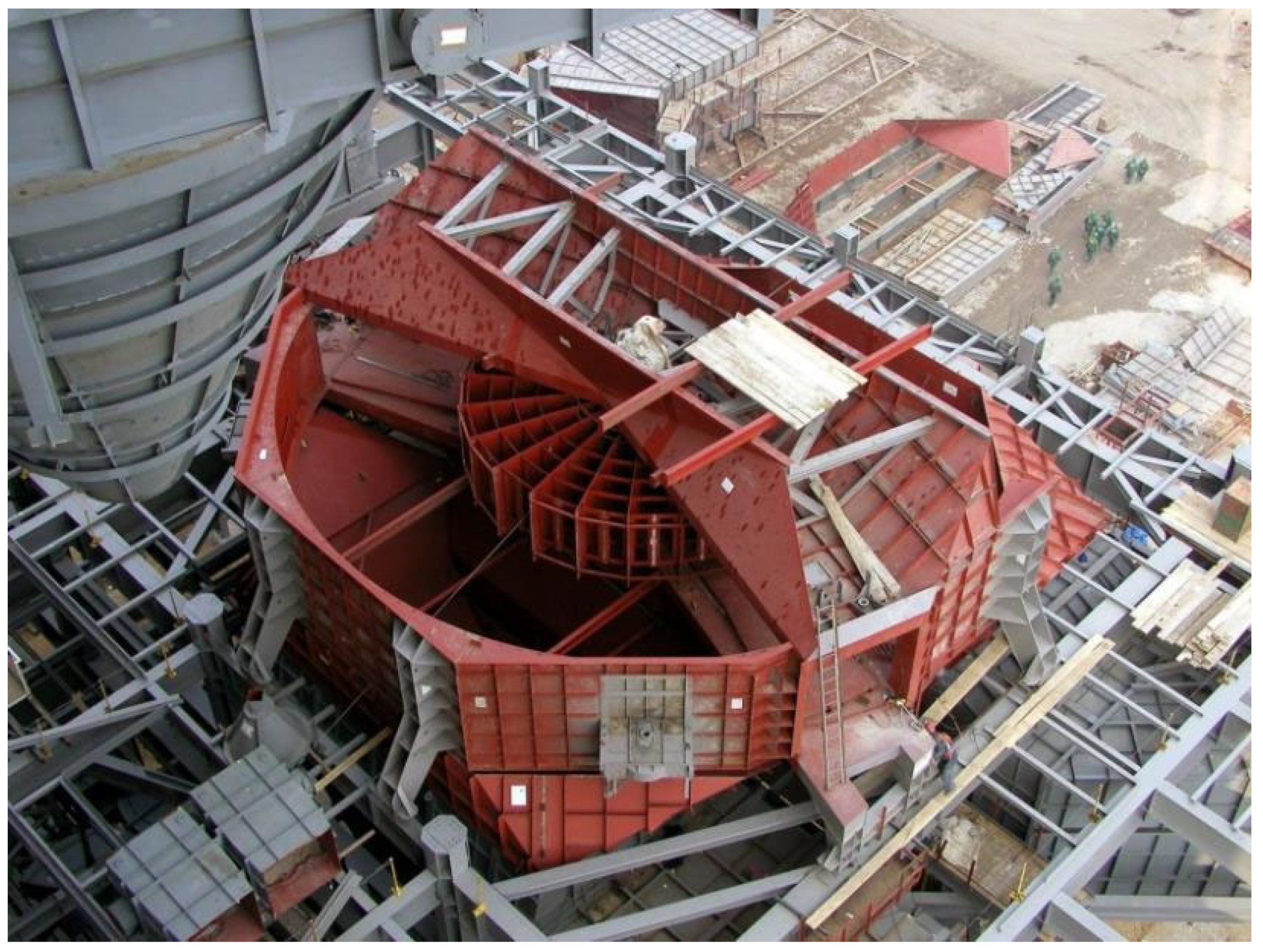
The rotary air preheater (LUVO,
Figure 1) is one of the auxiliary devices of a steam generator and consists of a rotor and its drive, flanged connections, bearings, seals, and housing. Its task is to recover the temperature from the exhaust gases leaving the boiler and to heat up the air flowing in the opposite direction. The heated air is used to heat up the dust that enters the boiler through coal burners to ignition temperature. The heat is transferred through a vertical-axis rotor.
The rotor of the rotary air preheater consists of a sheet metal structure, which is the main part of the heat exchanger, and two end pins supported on self-aligning spherical roller bearings (transverse on top, tapered at the bottom). These pins are fixed to the sheet metal element with a screw connection.
The application of a self-aligning spherical roller bearing in the top section of the preheater has a number of advantages. The most important one is the insensitivity to misalignment of the shaft in relation to the housing resulting from shaft deflection. In addition, spherical roller bearings can support high radial loads as well as high axial loads in both directions [
1,
2]. The entire rotor is enclosed in a sealed casing with flanged connections on top and bottom for exhaust gases and air.
The preheater casing divides the device into two zones: the flue gas zone and the air zone. Usually, the casing is divided into two sectors, but there are other possibilities depending on the required parameters, i.e., the required air heating temperature. The height and diameter of the rotor can also vary. The size of the device is chosen based on the size of the steam generator, and the efficiency of the preheater has a significant impact on the overall efficiency of the boiler.
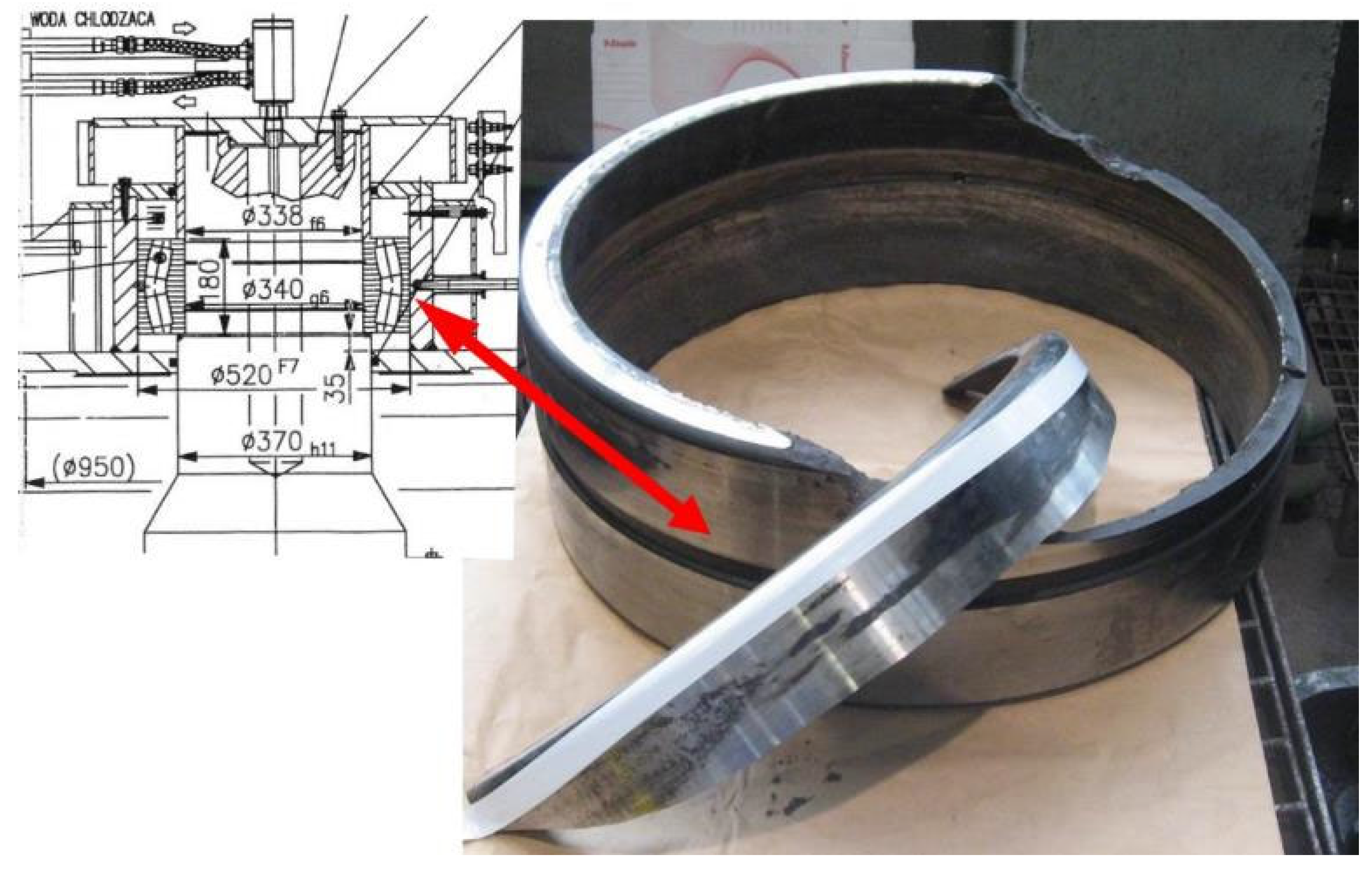
The bearing component of the aforementioned rotor in the rotary air preheater consists of an axial thrust bearing underneath the rotor and a guide bearing on top of the rotor. The rotor guide bearing is a double-row spherical roller bearing with an outer diameter of 520 mm with an F7 fit and an inner diameter of 340 mm with a g6 fit. The static radial capacity for that bearing is 6,199,830 N, and the axial capacity is the same value [
3].
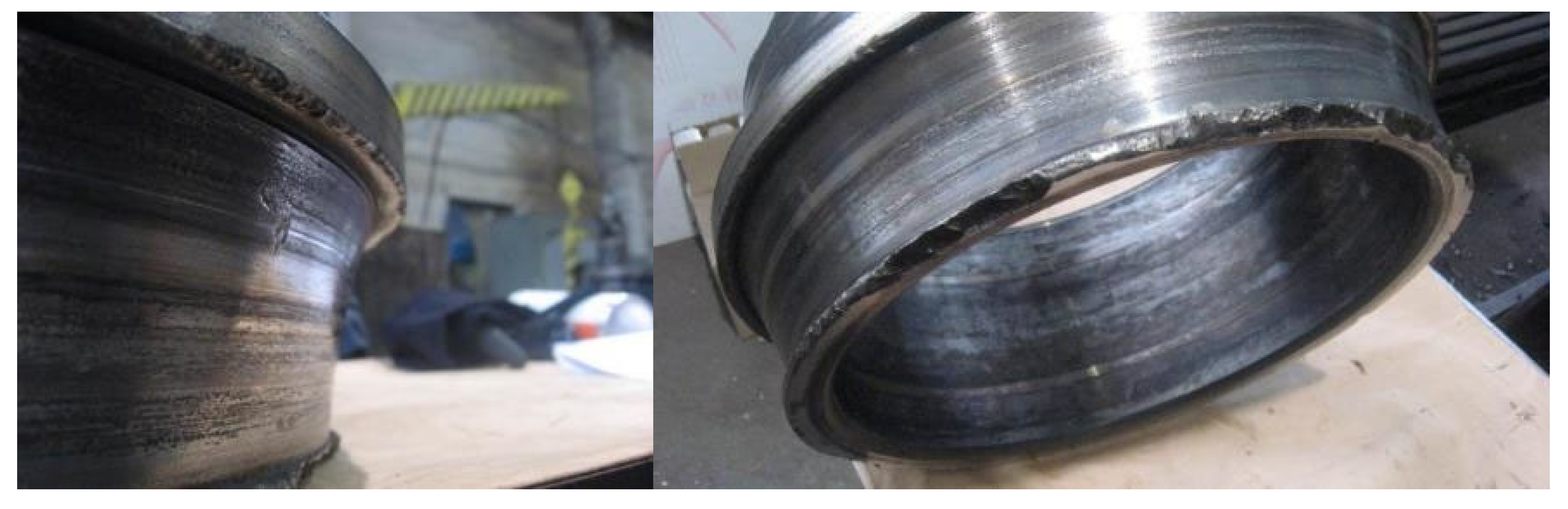
The damage to the self-aligning spherical roller bearing of the rotary air preheater is shown in
Figure 2.
Bearings are critical components in various mechanical systems, facilitating smooth motion and reducing friction between moving parts. However, the integrity of bearings can be compromised due to various factors, leading to cracks and subsequent failure. In one power plant, after several months of operation, there was an emergency shutdown of the preheater on a fluidized bed boiler due to damage to the top bearing. The aim of the research on this bearing was to conduct an analysis to identify a case of sudden destruction. The bearing worked for 6 months and was destroyed. The designed operating time of this bearing is 10 years. Due to such a period of planned operation, the analysis was carried out with the scope of immediate damages and not fatigue. The fatigue life of this bearing was not monitored.
2. State of Art
This summary examines research on bearing damage in industrial equipment, including wind turbines and rotary air preheaters. Bearing damage in rotary air preheaters is a critical issue that can lead to significant operational disruptions and maintenance costs. Understanding the causes and early detection methods for bearing damage is essential for maintaining the efficiency and reliability of these systems.
Monitoring vibration amplitude and temperature is crucial for detecting bearing issues, with values exceeding 4.5 mm/s and 70 °C indicating potential problems [
4]. Bearing damage can lead to significant operational disruptions, as seen in a power plant where gear failure caused a unit shutdown. Improper lubrication and installation procedures are common causes of bearing damage in compressors [
5]. In wind turbines, main bearing replacements occur earlier than expected, with 10% replaced by 10.5 years and up to 25% by 20 years [
6]. This paper provides a comprehensive review of the current theory and practice related to the main bearings used in wind turbines, including their design, operation, modeling, damage mechanisms, and fault detection. Spalling is the primary type of damage observed, often resulting from surface-initiated rolling contact fatigue. These findings highlight the importance of proper maintenance and monitoring to prevent bearing failures and extend equipment lifespan. This survey [
7] collects the efforts to understand the sources and consequences of damage to babbitted industrial bearings, which operate by means of a hydrodynamic, or hydrostatic, film. Major individual damage types are discussed in the context of major damage categories.
The paper [
8] examines the causes and mechanisms of bearing damage in aircraft gas turbine main shaft bearings, finding that the initial damage is often caused by surface defects and that the failure mechanism involves peeling and spalling of the bearing surface. An examination of approximately 200 bearing incidents in current aircraft engines has shown that damage in the bearing is initiated at the surface. The initial damage was produced by abrasive particles, dents, grinding scores, skidding, large carbides, and corrosion pits. The first phase of the failure mechanism appeared to be by peeling, where microscopic regions about 0.13 mm (0.005 in) were removed from the surface, and the peels eventually developed into spalls. These mechanisms of failure are a consequence of the partial EHD lubrication utilized in these bearings and the consequent sharing of the load by the asperities and the EHD film.
The paper [
9] reviews traditional algorithms used to detect and diagnose faulty ball bearings in rotating machinery. This paper shows traditional signal processing algorithms used to detect and diagnose faults in ball bearings of heavy-duty milling machine tool spindle heads. Different kinds of faults have been created deliberately on the bearings of a test spindle head.
The paper [
10] provides a comprehensive survey of theoretical and simulation approaches to understanding adhesive joint failures. This review, conducted within the framework of the CERTBOND initiative, focuses on methods applicable across aerospace, automotive, civil engineering, and other sectors. The authors examine nine models, including classical analytical methods, process zone methods, linear elastic fracture mechanics, the virtual crack closure technique, and the cohesive zone method, among others. Each model is discussed in terms of methodology, required parameters, advantages, disadvantages, and specific industrial applications. The review highlights both strengths and limitations of these models in handling complex factors like crack propagation, environmental effects, and composite materials, providing a critical comparative analysis that guides future improvements in adhesive joint certification and application.
The paper [
11] explores a method to assess bearing loads in hydraulic excavator drive systems. The authors develop a mathematical model to calculate the forces and moments experienced by the slewing bearings during operation. This model uses measurements of the excavator’s kinematic chain and hydraulic pressures to compute load vectors under real-world conditions. By analyzing these loads, particularly during the digging phase, the study provides insights to optimize bearing selection for durability and performance. This research contributes valuable data for improving excavator design, ensuring structural integrity and operational efficiency.
The paper [
12] investigates the thermal behavior of threaded spindle bearings in CNC machines. By focusing on ZKLN type bearings, the study uses finite-element analysis (FEA) to model heat generation and dissipation due to friction. The iterative process combines analytical methods and FEA simulations to optimize the thermal load calculations. The results reveal that while housing materials slightly affect heat distribution, managing thermal loads is essential for accurate machine performance, as heat can induce deformations that compromise precision. This work contributes a systematic approach for enhancing spindle bearing design in high-speed applications.
This summary examines failure analyses in various industrial applications. Cracking in air preheater components was attributed to microstructure degradation and high thermomechanical stress [
13]. API X70 steel, used in ethanol pipelines, showed susceptibility to stress corrosion cracking (SCC) and corrosion fatigue, particularly in notched specimens and under staggered constant load conditions [
14]. A comprehensive review of failure case studies highlighted issues such as buckling in pressurized vessels, fatigue failures in welded structures, and environmentally assisted cracking in various materials and components [
15]. In a liquid sulfur recovery unit, a 304 stainless-steel heat exchanger failed due to pitting corrosion, intergranular corrosion, and SCC caused by sulfuric acid and chloride ions [
16]. These studies emphasize the importance of understanding material behavior, environmental factors, and stress conditions in preventing industrial failures.
For wind turbines, premature main bearing failures primarily result from rolling contact fatigue, often requiring replacements much earlier than expected. Aircraft turbine bearings frequently fail due to surface defects and spalling initiated by abrasives and corrosion. A review paper on ball bearing fault detection discusses traditional signal processing methods, while another paper investigates adhesive joint failures and presents various modeling techniques to predict crack propagation under industrial conditions.
Cracked bearings represent a significant challenge in mechanical systems, with implications for performance, maintenance, and safety. By understanding the causes of bearing cracks and implementing effective mitigation strategies, engineers and maintenance personnel can enhance the reliability and longevity of bearing systems. Overall, these studies emphasize that proactive maintenance and optimized design, supported by analytical and simulation models, are crucial for extending equipment lifespan and reliability across industries.
3. Chemical Composition Analysis
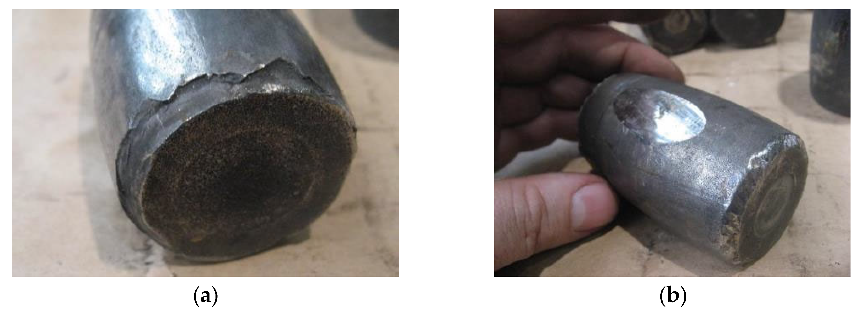
At the beginning of research, the chemical composition was analyzed with a spectrometer to determine the type of material used for the bearing [
17,
18]. All elements of the bearing were tested, i.e., the inner ring, damaged outer ring, spherical roller elements, and cage (
Figure 3).
Table 1 shows the identified alloying elements and their percentage in the material of the damaged outer ring of the bearing.
Based on the percentage composition of elements, it was determined that the material that best matches this composition is AISI 6150 alloy steel (1.8159/51CrV4) [
18]. Mechanical properties of that steel are shown in
Table 2. The most important are the tensile and yield strength of that steel.
During X-ray analysis, the spectrometer detected exceedances for some alloying elements contained in this steel (marked red—
Table 1). When analyzing the different percentages of individual elements, it should be noted that each bearing manufacturer uses its own proprietary technology to manufacture bearing parts. This is why small exceedances in the percentage of alloying elements for the identified steel grade are acceptable.
The material used for the outer ring of the bearing is highly wear-resistant. It has a very good impact strength and is highly resistant to dynamic loads (higher-class heat treatment). Therefore, this material is commonly used in loaded machine parts such as shafts, gears, gearboxes, and rolling elements operating at high temperatures [
18]. Moreover, during production, individual elements of bearings, i.e., the outer and inner rings and rolling elements, are subjected to 100% UT inspection (ultrasonic testing).
6. Finite-Element Analysis
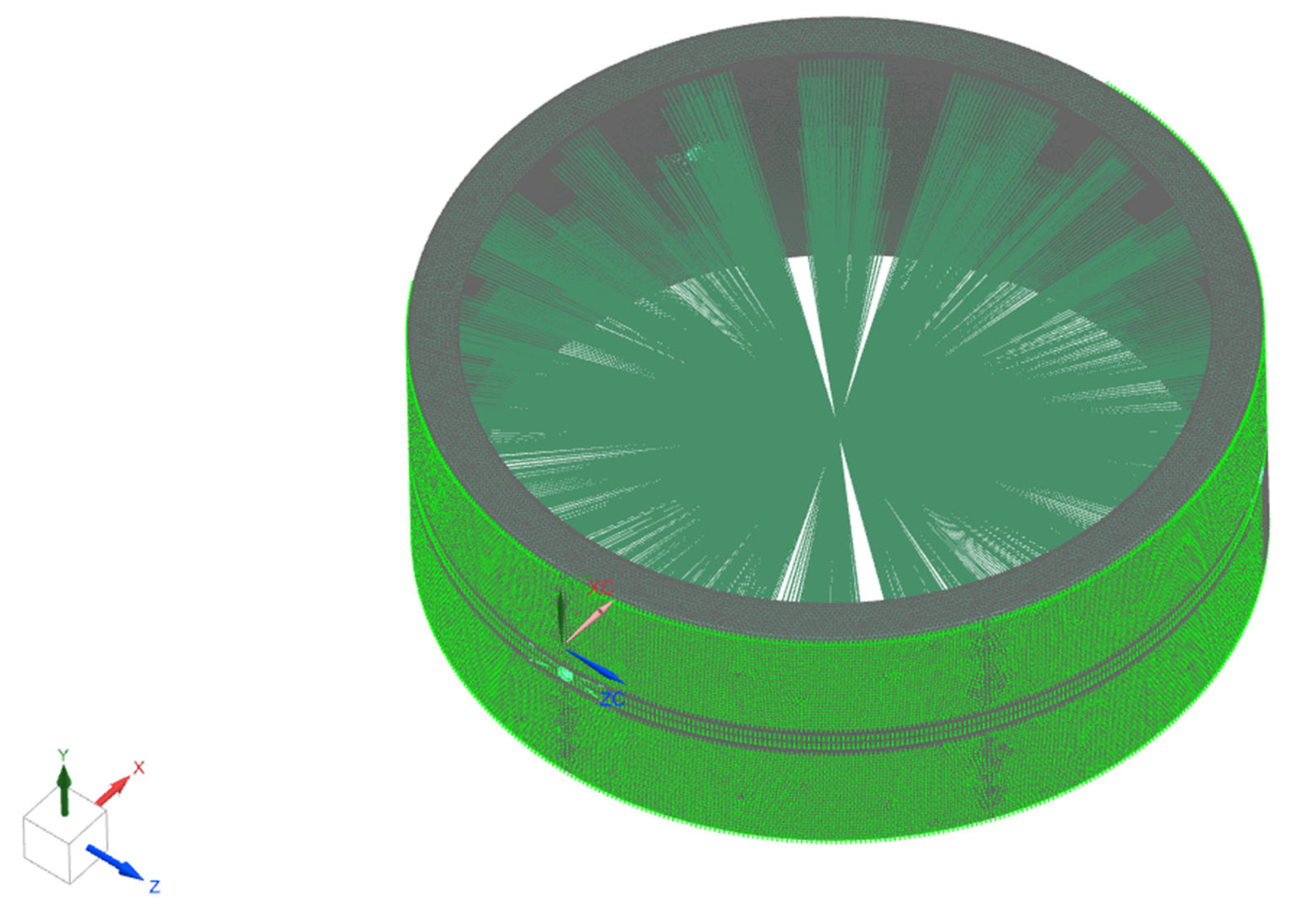
Based on the documentation provided for the upper rotary shaft of the air heater, a numerical model was built.
A load was applied to the model in the form of forces causing a bending moment of the shaft and pressure applied to the lubrication holes; the model was supported on bearings in accordance with the documentation, shown in
Figure 13.
The values of the loads adopted for numerical calculations are as follows:
| force causing a bending moment: | F1 = 14.5 kN |
| lubricant pressure: | p = 0.1 MPa |
| rotation speed: | v = 1.1 min −1 |
The numerical model with loads is shown in
Figure 14.
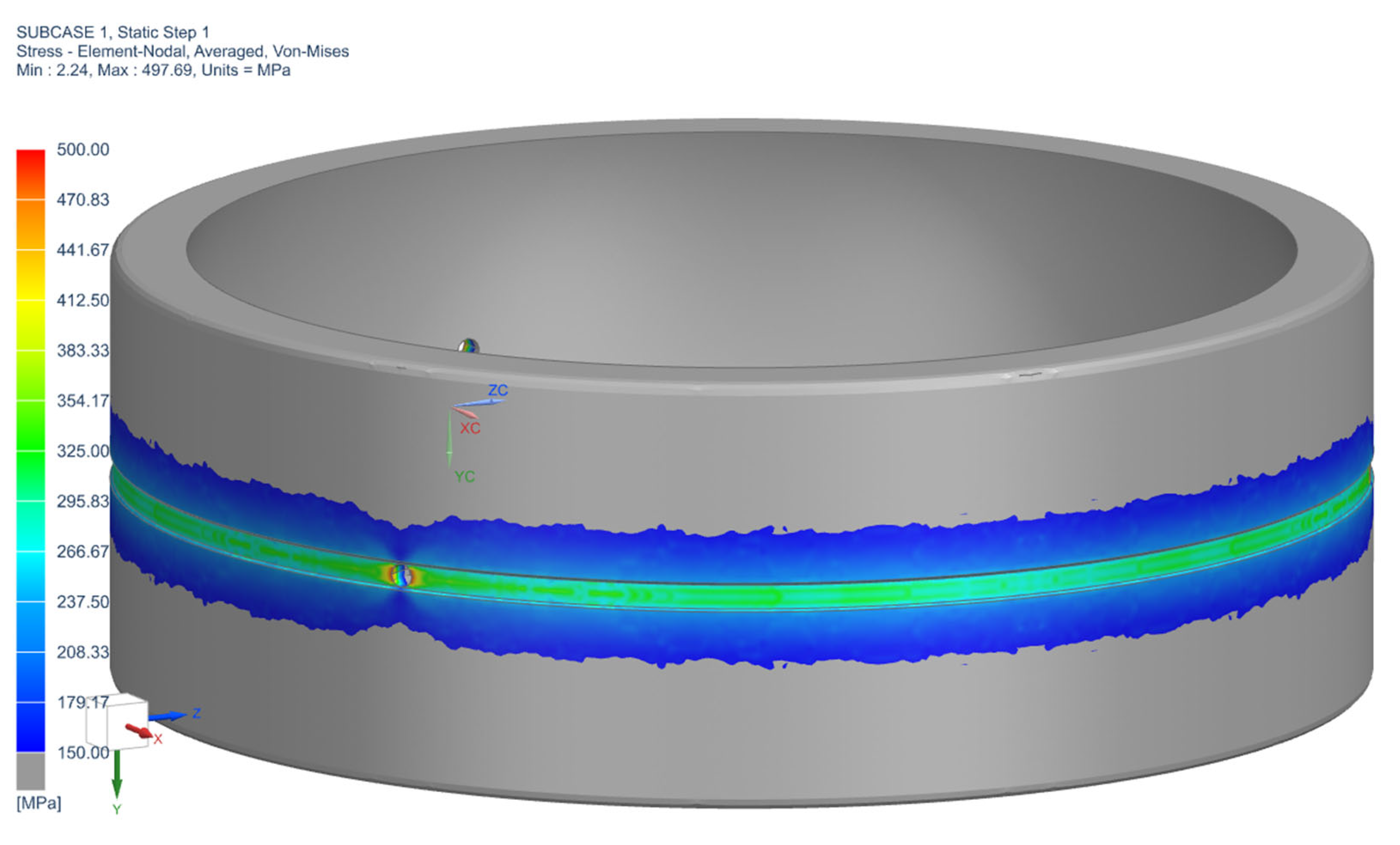
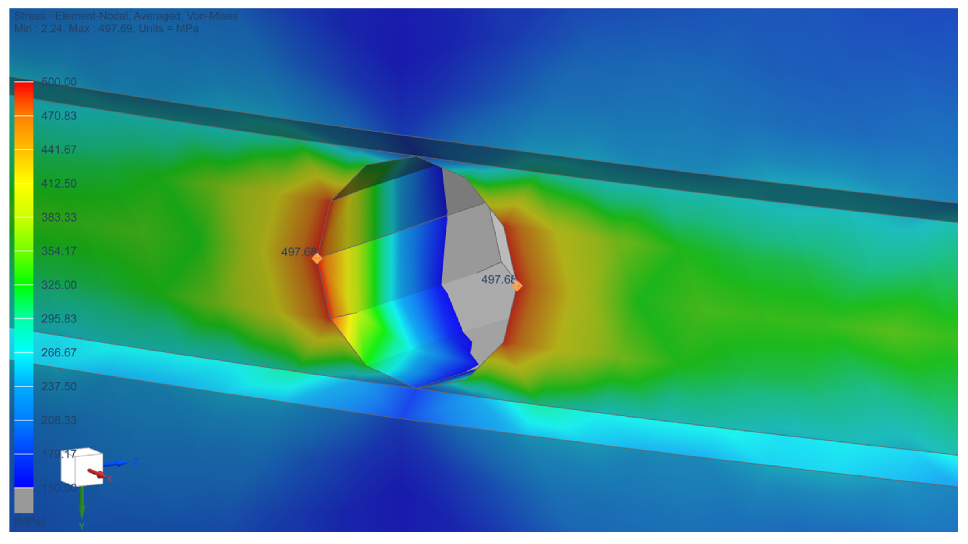
Strength calculations were performed, and the results of calculations indicating the places of maximum stress of the bearing raceway are shown in
Figure 15 and
Figure 16. The highest stress values were obtained in the area of the lubrication introduction holes. The values reach 498 MPa, which is above the value of yield strength of AISI 6150 alloy steel (1.8159/51CrV4). In those conditions, the crack appeared next to the lubricant hole.
The stress around the grease hole was above the yield limit for steel AISI 6150 alloy steel (1.8159/51CrV4), which caused the material to plasticize and became the site of crack initiation. This became one of the main reasons for the failure of the bearing.
7. Conclusions
The material of the bearing was tested for chemical composition and hardness. By measuring the percentage of individual alloying elements in the steel, it was determined that the material used to build the bearing satisfies the standards and complies with the documentation of the device manufacturer. The hardness of the material was measured in order to verify that the correct heat treatment process was selected for the bearing components. The obtained hardness values (~62 HRC) confirmed that correct heat treatment was used for the bearing.
Based on the abovementioned results of the material tests, it was determined that the failure was not caused by poor quality of the supporting bearing. The design error caused the appearance of a crack in the bearing raceway, which later caused the destruction and damage of the entire bearing.
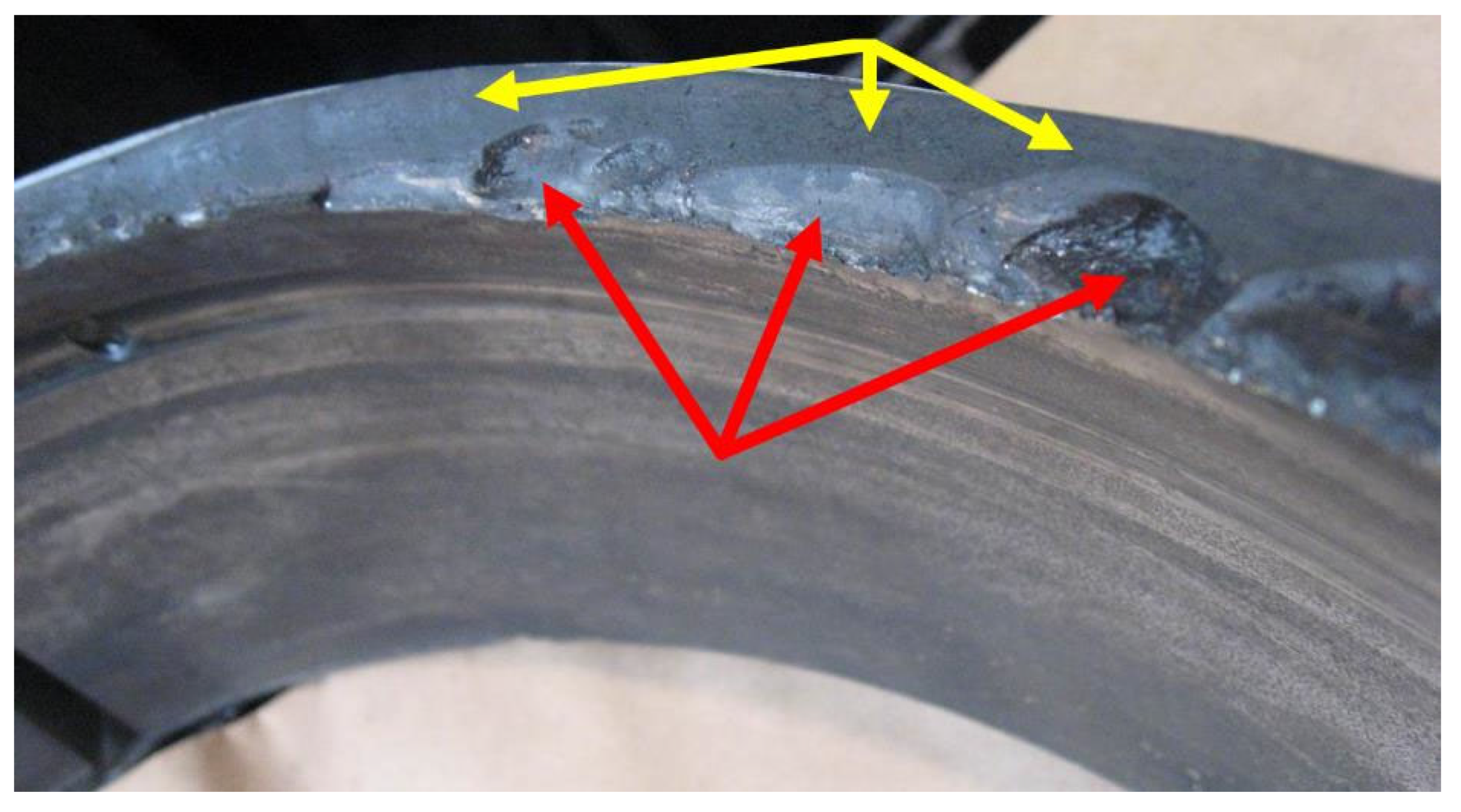
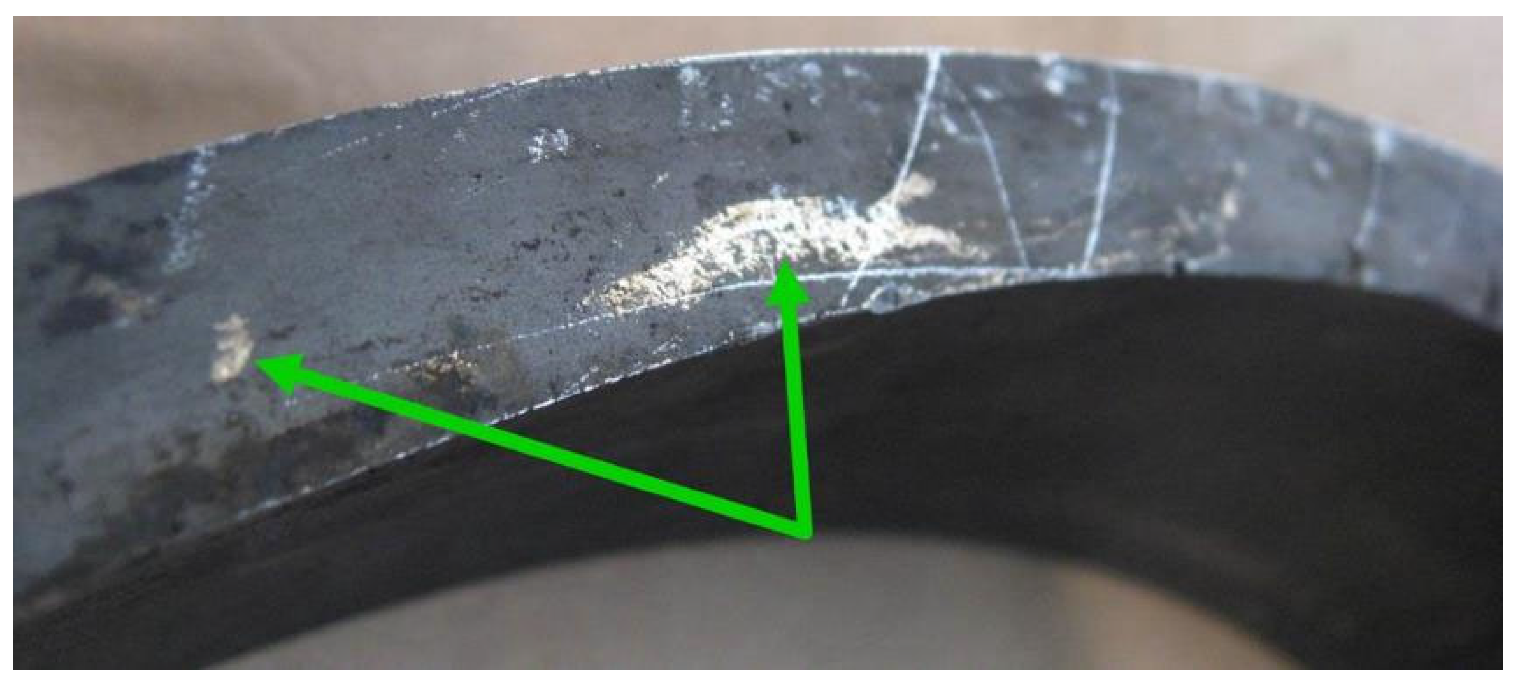
Non-destructive testing was the step in determining the cause of bearing damage. The test results identified damage in the form of a crack in the bearing’s outer ring, material flaking, and seizures of the inner raceway and fractures of its side surface. In addition, the visual inspection revealed the presence of fretting, which propagated during operation and became one of the main causes of damage to the rotary air preheater bearing. Fretting usually occurs when the fit is insufficient/too loose and there is relative motion between the bearing ring and housing. Relative motion is usually caused by shape inaccuracies or shaft deflection and causes small pieces of the material to split off from the surface of the seat in the housing. These pieces oxidize quickly upon contact with air. The corrosion on the outer ring (
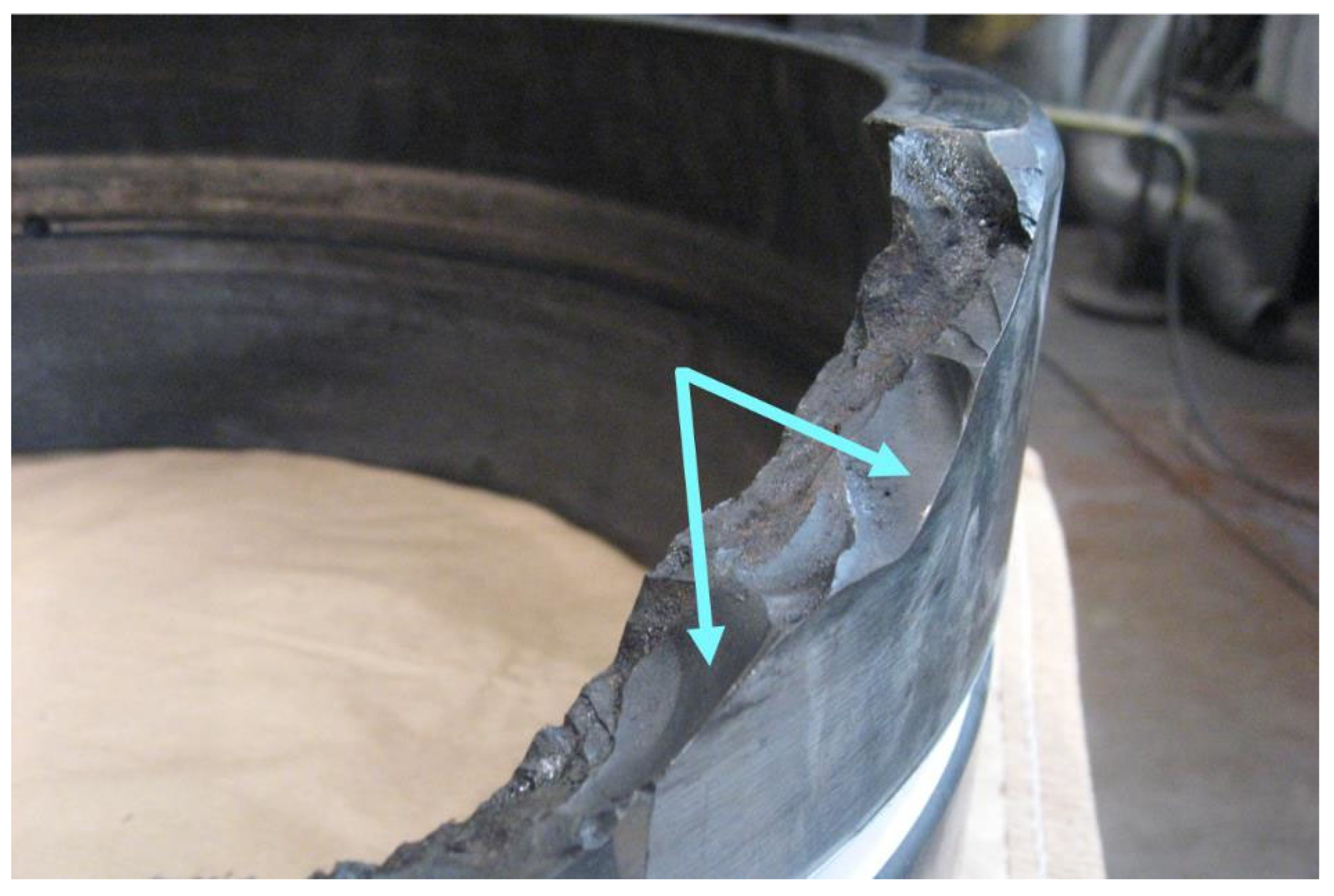
Figure 11) produces local shape imperfections on the surface of the bearing seat; the volume of iron oxide is larger than that of pure steel. The natively concave and convex bearing seat resulted in insufficient fit between the bearing ring and the seat surface along its width, which is why it deflected under load, resulting in a fatigue crack on the circumference of the ring raceway; the ring cracked at its weakest point, in the oil groove. The likely direction of propagation and the resulting loss of material integrity of the outer ring is shown in
Figure 17.
The fretting, which resulted in the failure of the air preheater, could have also been caused by human error when the bearing seat was mounted.
To sum up, as a result of the performed tests, it was determined that the direct cause of failure of the rotary air preheater support was fretting, which occurred due to a design error—the fit was insufficient—and/or there where manufacturing flaws—incorrect mounting of the bearing in the housing.


