Article

Numerical Simulation and Analysis of Semi-Industrial Retrofit for Tangentially Fired Boilers with Slag-Tap Technology

1
Xi’an Thermal Power Research Institute Co., Ltd., Xi’an 710032, China
2
Harbin Boiler Co., Ltd., Harbin 150046, China
3
State Key Laboratory of Multiphase Flow in Power Engineering, School of Energy and Power Engineering, Xi’an Jiaotong University, Xi’an 710049, China
*
Author to whom correspondence should be addressed.
Energies 2024, 17(24), 6331; https://doi.org/10.3390/en17246331
Submission received: 20 November 2024 / Revised: 10 December 2024 / Accepted: 13 December 2024 / Published: 16 December 2024
(This article belongs to the Section J: Thermal Management)

Abstract

:
High-alkali Zhundong coal presents significant challenges for power generation, due to its propensity for fouling and slagging. This study investigates a retrofit of a 300 MW tangentially fired boiler with the integration of a slag-tap chamber to improve combustion performance. Computational fluid dynamics (CFD) simulations are employed to examine the influence of this modification on combustion dynamics and the effects of Zhundong coal blending ratios on heat and mass transfer. The results demonstrate that the retrofit facilitates stable airflow recirculation, optimizing combustion efficiency with a peak temperature of 2080 K in the combustion chamber. The flue gas temperature decreases to approximately 1650 K upon exit, which can be attributed to the slag catcher cooling. The integration of the liquid slagging chamber significantly mitigates slag formation, while enhancing oxygen and CO2 distribution throughout the furnace. As the blending ratio of Zhundong coal increases, oxygen concentrations rise in the bottom burner region, indicating improved air–fuel mixing. With a 30% Zhundong coal ratio, the combustion chamber temperature increases by 3%, and flow velocity in the upper and middle furnace sections decreases by 15%, leading to enhanced combustion intensity. This retrofit demonstrates substantial improvements in combustion stability, slagging control, and the efficient utilization of high-alkali coal.

1. Introduction

High-alkali coal resources in Xinjiang are abundant, yet the elevated concentrations of alkali and alkaline earth metals (Na, K, Ca, Fe) in these coals pose significant challenges regarding their use in power generation. The resulting fouling and slagging issues critically hinder the economic, efficient, and stable operation of boilers burning Xinjiang high-alkali coal [1,2,3,4]. In conventional solid-state slagging furnaces, the direct combustion of high-alkali coal often leads to severe fouling on heating surfaces, slag formation within the furnace, and excessive flue gas exit temperatures, thereby limiting the large-scale utilization of high-alkali coals [5].
To mitigate these issues, measures such as reducing the furnace volumetric heat load, decreasing wall heat load in burner zones, installing additional soot blowers, and increasing the spacing between heating surfaces have been implemented to mitigate slagging and fouling. However, for certain types of high-alkali coals with a high tendency to exhibit slag flow, these solutions remain insufficient for complete combustion [6,7]. In response to the severe slagging problem, many power plants have adopted coal-blending strategies, which involve mixing high-alkali coal with low-sodium coal or alternative fuels [8,9,10,11,12,13,14,15]. Liu et al. [16] investigated the co-firing characteristics of bituminous coal with high-alkali coal, demonstrating that a co-firing ratio exceeding 20% can effectively reduce the severity of slagging. Similarly, Wang et al. [17] examined the feasibility of blending high-alkali coal with high-Fe/Al coal, finding that this co-firing approach alleviates ash deposition. These findings underscore the potential of blending strategies to enhance the combustion performance of high-alkali coals, thereby contributing to the overall efficiency and stability of boiler operations.
Slag-tap boilers, developed to accommodate coals that are both difficult to ignite and prone to slagging, provide a promising alternative [18,19]. Common types of slag-tap boilers include vertical cyclone combustion slag-tap boilers and horizontal cyclone combustion slag-tap boilers. Recent studies in this area have contributed valuable insights into their design and performance. For instance, Ren et al. [20] conducted a numerical simulation study on a horizontal cyclone slag-tap combustor, focusing on optimizing the combustor dimensions and the arrangement of the secondary air supply. Lan et al. [21] investigated the performance of Zhundong high-chlorine, high-sodium coal in a horizontal slag-tap boiler experimental setup. Additionally, Hu et al. [22] examined the growth and compositional characteristics of ash within a horizontal cyclone slag-tap boiler, through experimental methods. These studies enhance the applicability of slag-tap boilers to high-alkali coal utilization, showcasing their advantages, such as high combustion intensity, high slag capture efficiency, and low dust content in the flue gas.
The advancement of slag-tap technology and slag-tap boilers offers a promising pathway for the efficient utilization of high-alkali coal. Slag-tap technology effectively addresses issues such as ash slagging, corrosion, and wear by leveraging high combustion intensity and efficient slag capture. Previous research [18,19,20,21,22] has demonstrated that in horizontal liquid slag furnaces, the optimized design of the combustion chamber and the strategic arrangement of secondary air supply can enhance combustion characteristics and significantly improve the efficiency of high-alkali coal combustion. Additionally, investigations into slag-tap boilers, including vertical and horizontal cyclone-fired designs, have further validated their feasibility for high-alkali coal utilization. These studies [20,21,22] highlight their advantages, such as a high combustion intensity, low particulate emissions, and robust slag management capabilities, underscoring their potential in mitigating the challenges associated with high-alkali coal combustion.
In existing coal-fired power plants, tangential firing boilers represent a substantial portion of the installed fleet. However, the heating surfaces of these boilers are prone to slagging, which severely diminishes their operational productivity and escalates maintenance needs [23,24,25,26]. As a high-intensity combustion technology with high slag capture efficiency, slag-tap technology presents a viable solution for the effective utilization of high-alkali coals. This technology mitigates several critical issues associated with furnace safety, such as ash slagging, corrosion, and the erosion of heated surfaces, particularly when using Zhundong coal. Wu et al. [18] investigated the ash slagging characteristics and elemental migration behaviors of Zhundong coal in a horizontal slag-tap furnace with a capacity of 20 MW. A promising strategy for ensuring the complete combustion of high-alkali coal while simultaneously lowering the costs of constructing new boilers involves maintaining the existing combustion and slagging methods, along with adding a slag-tap chamber at the rear of the furnace. Despite the potential advantages of this approach, there has been limited research evaluating its feasibility.
In this study, a semi-industrial retrofit is developed to incorporate a slag-tap chamber at the rear of the furnace, while maintaining the original combustion and slag-tap mechanisms of the boiler. A 300 MW tangentially fired boiler is selected as a case study for this retrofit, and numerical simulations are conducted with CFD to analyze the alterations in combustion characteristics and airflow within the furnace, following the retrofit. Furthermore, the effects of Zhundong coal blending ratios on the aerodynamic field, temperature distribution, and component concentrations within the furnace are systematically analyzed. The proposed retrofit aligns with global efforts to achieve net-zero CO2 emissions by enhancing combustion efficiency, facilitating the use of alternative fuels, and reducing the overall carbon footprint. By optimizing the combustion process, the retrofit decreases fuel consumption per unit of energy generated, thereby directly lowering CO2 emissions. Its flexibility in accommodating coal blends and alternative fuels with a lower carbon content further reduces the carbon intensity of energy production. Additionally, improved combustion stability and efficiency minimize auxiliary emissions, such as unburned carbon, contributing to cleaner and more sustainable energy generation. These advancements support the decarbonization of coal-fired power plants, aligning with international climate targets and the transition toward a sustainable energy future.

2. Boiler Structure and Geometry

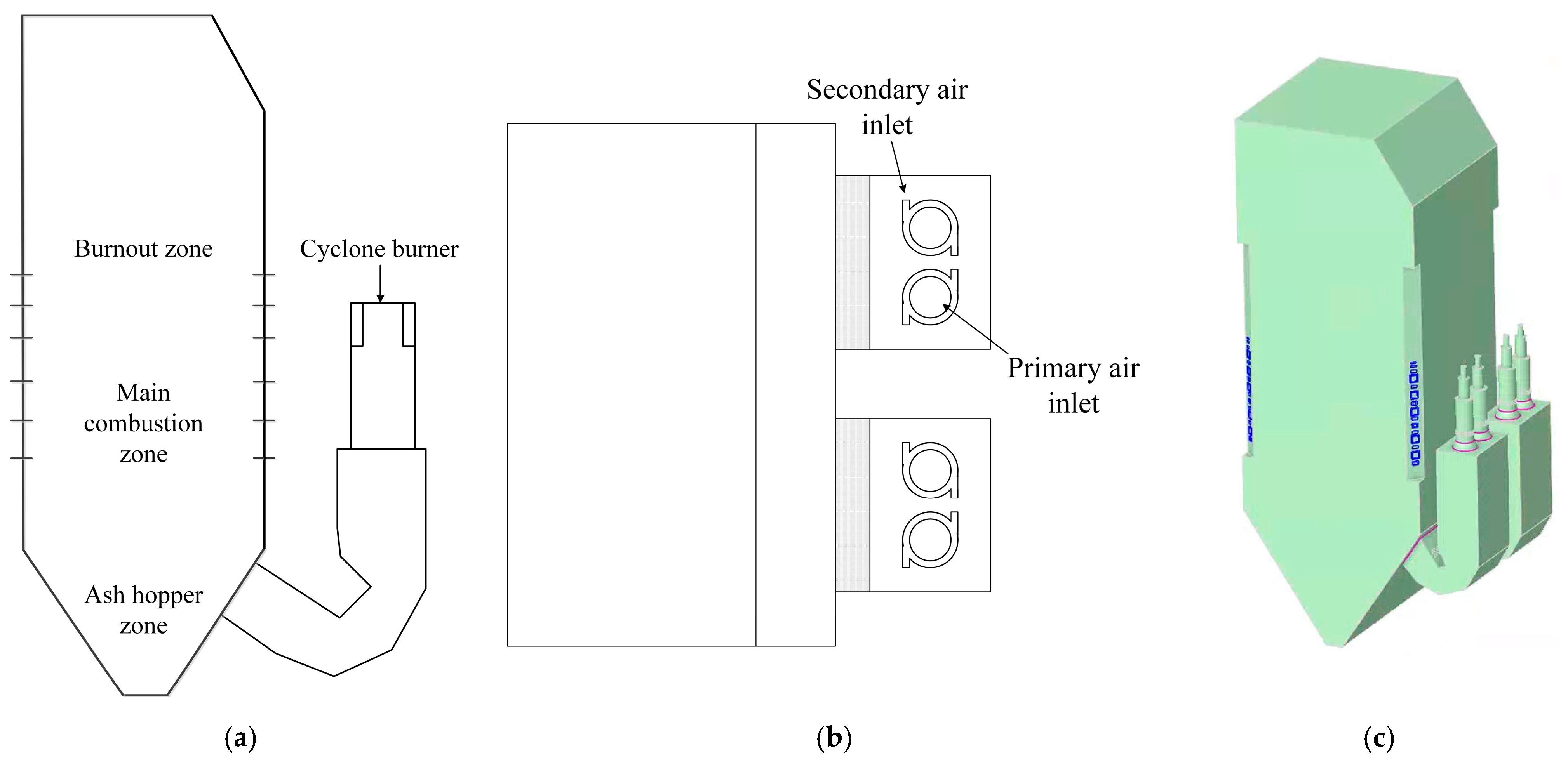
2.1. Original Model of the Boiler

This study focused on a 300 MW subcritical natural circulation boiler, utilizing a tangential firing system with five burner levels and incorporating a vertical water-cooled wall design. The design parameters are outlined in Table 1, and the overall layout of the boiler is illustrated in Figure 1. The ash hopper zone is labeled in Figure 1, in which (a) represents the original slag discharge location. During the combustion process, high-temperature slag generated in the boiler’s combustion chamber falls into the cold ash hopper below, driven by gravity. After cooling, the slag exits through the ash outlet at the bottom of the hopper and is directed into the slag discharge unit. The boiler utilizes bituminous coal as its fuel, with the fuel characteristics as analyzed and presented in Table 2. Proximate analysis was conducted, following the standards outlined in ASTM D3172-13 [27] or GB/T 212-2008 [28]. The moisture, ash, and volatile matter contents were determined directly, and fixed carbon was calculated by subtracting the other components from 100%. Ultimate analysis was performed using an elemental analyzer (e.g., CHNS analyzer) in accordance with ASTM D3176-15, Standard Classification of Coals by Rank or GB/T 476-2008, Classification of Bituminous Coal. This method measured the contents of carbon, hydrogen, nitrogen, and sulfur directly, while the oxygen content was determined by difference. Standards for bituminous coal, such as ASTM D388-19, Standard Classification of Coals by Rank or GB/T 5751-2009, Classification of Bituminous Coal, exist and are commonly used for classification and analysis, both of which were referenced in this study.

2.2. Modified Model of the Boiler

This semi-industrial modification scheme involves the addition of a separate slag-tap combustion chamber at the rear of the furnace, without altering the original combustion and slagging methods of the boiler. This new combustion chamber replaces one of the burners corresponding to a coal mill in the original boiler configuration. The outlet of the slag-tap combustion chamber connects to the inclined cold ash hopper at the bottom of the original boiler’s furnace. The high-temperature flue gas generated in the slag-tap combustion chamber is directed through a slag capture pipe into the original boiler furnace, where it mixes with the high-temperature flue gas produced within the original furnace.
In this semi-industrial modification scheme, the combustion chamber features four vertically arranged burners, representing one-quarter of the number found in the double-U flame slag-tap boiler design [29]. The shape of the semi-industrial validation combustion chamber closely resembles that of the double-U flame slag-tap boiler. However, the depth of the combustion chamber is reduced post-modification, and it is also divided into two sections in the width direction.
Based on the structural characteristics of the semi-industrial validation scheme, a geometric model of the slagging boiler is constructed at a 1:1 scale, as illustrated in Figure 2. The boiler combustion chamber is equipped with four cyclone burners, the design of which is consistent with that of the cyclone burners used in the double-U flame slag-tap boiler scheme. The furnace features five layers of burners, arranged in a tangential circular configuration.

3. Numerical Simulation

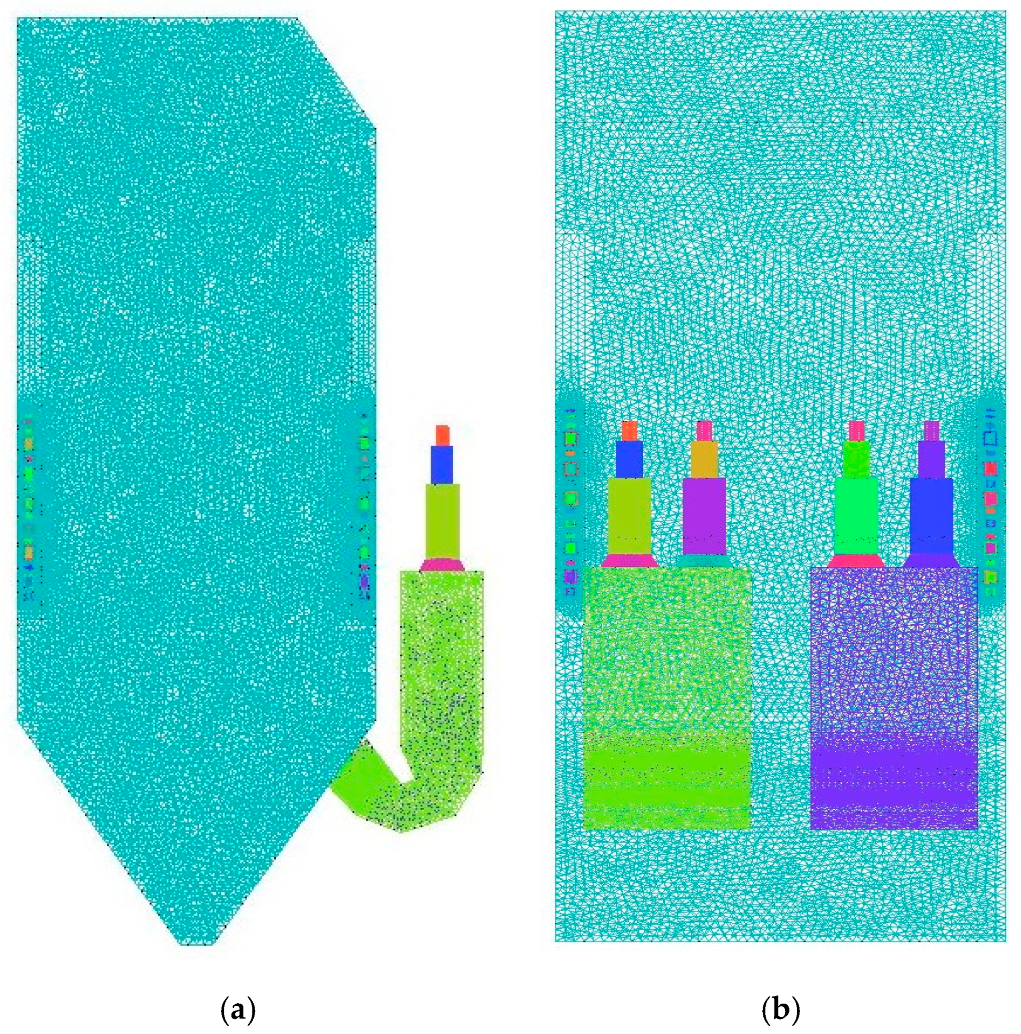
3.1. Grid Generation

In this study, an unstructured numerical grid is employed for the slag-tap boiler, utilizing specialized meshing software for the meshing process. In the numerical simulations, computational accuracy typically increases with mesh density. However, beyond a certain threshold, further refinement yields diminishing returns in accuracy, while significantly reducing the computational speed and also increasing costs.
To address specific structural and operational requirements, different meshing strategies are implemented in various regions of the boiler. In the burner and combustion chamber, where intense chemical reactions occur, a dense hexahedral mesh is utilized to ensure the necessary accuracy and to accommodate the complex geometry. Conversely, in the upper section of the cooling chamber, where heat and mass transfer are limited due to its regular shape, a sparser hexahedral mesh is adopted. This strategic meshing approach enhances overall simulation fidelity, while effectively addressing the unique challenges associated with each boiler region. The grid structure is illustrated in Figure 3.
To mitigate the impact of grid count on the simulation outcomes, three distinct grid configurations are generated for the grid independence test, with total node counts of 2,321,273, 3,241,269, and 4,368,417, respectively. All three grids are constructed with an identical meshing strategy. The distributions of average horizontal gas temperature in the furnace for different grid configurations under boiler maximum continuous rating (BMCR) conditions are presented in Figure 4. When the number of grids increases from 3,241,269 to 4,368,417, the trend of the average horizontal gas temperature in the furnace remains consistent. At this point, further increases in grid density have a negligible effect on the temperature distribution within this region. Considering both computational efficiency and accuracy, the grid with 3,241,269 cells (the maximum cell size is 0.3 m) is selected as the final grid for this study.

3.2. Basic Equations for CFD Simulation

In fluid dynamics, the equations governing mass conservation (continuity equation), energy conservation (Bernoulli equation), and momentum conservation (Navier–Stokes equation) form the foundation for describing ideal fluid flow phenomena [30,31]. These equations enable the determination of essential parameters, such as velocity, temperature, and pressure, at specific points in time and space within complex flow fields. Additionally, the Bernoulli equation is used as a simplified representation of energy conservation, particularly for incompressible flows, by relating pressure, velocity, and height in the flow field. These equations facilitate the derivation of other relevant physical quantities, allowing for a comprehensive analysis of fluid behavior.
According to the law of mass conservation, the working mass must satisfy the mass conservation equation, commonly referred to as the continuity equation. This principle dictates that the rate of mass increase within a differential volume element equals the net mass flow rate entering that element. The continuity equation is expressed as follows:
ρ t + div ( ρ u ) = 0
where ρ represents the fluid density (kg m−3), t denotes time (s), and u is the velocity (m s−1).
The momentum conservation equation, commonly represented by the Navier–Stokes equations, states that the rate of change of momentum within a fluid element is equal to the sum of the external forces acting upon it. Derived from the law of momentum conservation, the Navier–Stokes equations are formulated to account for both viscous and inertial effects in fluid flow. In terms of Cartesian coordinates, the momentum conservation equations can be defined by:
( ρ u ) t + div ( ρ u u ) = div ( μ grad u ) p x + F x
( ρ v ) t + div ( ρ v u ) = div ( μ grad v ) p y + F y
( ρ w ) t + div ( ρ w u ) = div ( μ grad w ) p z + F z
where u , v , and w are the velocity components (m s−1) in the x , y , and z directions, respectively, μ represents the kinematic viscosity (m2 s−1), p denotes the static pressure (Pa), and F x , F y , and F z are the components of the body force per unit mass (N kg−1) in the x , y , and z directions, respectively.
The energy conservation equation describes the balance of thermal energy within a fluid element, accounting for heat transfer, work done by pressure forces, and changes in internal energy. Based on the law of energy conservation, this equation quantifies the thermal behavior associated with fluid motion and external heat sources. The energy conservation equation is formulated as:
( ρ T ) t + div ( ρ u T ) = div ( k C p grad T ) + S T
where T represents the thermodynamic temperature (K), k accounts for the fluid heat transfer coefficient (J m−2 K−1), C p reflects the specific heat capacity of the fluid (J kg−1 K−1), and S T represents the internal heat source term (W m−3).

3.3. Numerical Methods

ANSYS Fluent 2022 R1 software is employed for the numerical simulations. During the numerical calculation process, Fluent discretizes the governing equations for key physical quantities, including energy, velocity, and species concentration, based on the computational grid, and iteratively solves for each quantity within each grid cell [32]. In this study, the energy equations are activated to model heat transfer both within the fluid and between the fluid and the wall surfaces. The realizable k-ε model is selected to simulate the turbulent flow field in the flue gas phase [33]. The SIMPLE algorithm is applied due to its stability and rapid convergence rate, making it well-suited for relatively straightforward flow fields [34]. Given the minimal pressure variation and low flow velocity of the flue gas, a pressure-based solver is selected, with the Green–Gauss cell-based method chosen for gradient calculations. The first-order upwind scheme is applied for spatial discretization. The species transport model is selected to represent component mixing, with the physicochemical properties of the materials, including species mass fractions and other physical parameters, being defined in detail. In Fluent, the gas–phase reaction models include the finite rate/eddy dissipation model, the eddy dissipation concept (EDC) model, and the eddy dissipation model. The finite rate/eddy dissipation model combines the Arrhenius equation, for reactions with low net rates, and the eddy dissipation equation, effectively integrating both kinetic and turbulence effects for higher computational accuracy. The EDC model assumes that chemical reactions occur within fine-scale turbulent structures over a specific time scale, enabling the precise simulation of the overall chemical reaction process; however, this demands significant computational resources and is typically applied to reactions with slower rates. In contrast, the eddy dissipation model emphasizes the role of turbulent mixing in controlling fuel reaction rates, while neglecting molecular transport and chemical kinetics, making it less accurate for detailed reaction modeling. In this study, the finite rate/eddy dissipation model was selected for all gas–phase reactions, due to its balance of accuracy and computational efficiency.
To optimize computational efficiency, the flow and turbulence equations are initially solved to achieve flow field convergence. Once the flow field has converged, additional equations and the discrete phase model (DPM) are activated. Due to the time-intensive nature of DPM calculations, DPM iterations are set to execute for every 30 iterations of the continuous flow field.

3.4. Boundary Conditions

In this study, the operating conditions in the numerical simulation are shown in Table 3. The air inlet boundary conditions are defined using mass flow inlet boundaries, with the mass flow rate at each inlet being set according to the actual airflow distribution. The outlet boundary condition is specified as a fully developed flow outflow, with the outlet pressure set to atmospheric pressure. This boundary condition assumes that all flow variables, except for pressure, are normalized to zero, approximating a fully developed flow. However, this condition cannot simulate the physical phenomenon of reflux in the final results and is intended for use exclusively in conjunction with the velocity inlet boundary condition. All walls of the computational domain are defined as isothermal walls with no-slip boundary conditions [23,35].

3.5. Working Conditions

In the semi-industrial retrofit scheme, only the combustion chamber burns Zhundong coal, while the five-layer burners in the furnace utilize the coal for which it was designed, resulting in a mixed-fuel combustion process. The coal quality characteristics of Zhundong coal are presented in Table 4. The proportion of coal burned in the combustion chamber significantly impacts the simulation results. In this study, the proportion of Zhundong coal in the combustion chamber is set to 25% by weight. To investigate the combustion characteristics of the modified furnace and assess the influence of Zhundong coal blending on the aerodynamic field, temperature distribution, and component concentrations within the furnace, the details of three BMCR working conditions are provided in Table 5. Coal blending ratios concern the proportion (by weight) of Zhundong coal in the total coal mixture that is used for combustion in the combustion chamber.

4. Results and Discussion

4.1. Simulation Model Validation

Thermal calculations describe the process of evaluating the thermal performance of the boiler. The flue gas inlet and outlet temperatures across the heat transfer surfaces of the boiler can be determined through thermal calculations [36]. Since the boiler in this study represents a retrofit design and lacks actual operational data for reference, the thermal calculation results were used to validate the accuracy and reliability of the numerical model employed. In this study, the results of CFD simulations were compared with thermal calculations to verify the reliability of the numerical model. Thermal calculation refers to the process of evaluating the thermal performance of a boiler, providing the inlet and outlet temperatures of the flue gases flowing through each heating surface. Since the boiler in this study was part of a retrofit scheme, no actual operating data were available for direct comparison. Therefore, the results of previous thermal calculations were employed to validate the numerical simulations.
Working condition 2 was selected for model validation, and the calculated results were compared with the numerical results, as presented in Table 6. The numerically simulated maximum combustion temperature is 2224.7 K, which is 31.5 K higher than the maximum combustion temperature obtained from the thermal calculations. At the bottom of the platen, the numerically simulated temperature is 1468.5 K, while the thermally calculated temperature is 1438.4 K. According to comparisons with previous studies [36,37], the discrepancies observed in this study fall within an acceptable range, thus demonstrating the accuracy and reliability of the numerical model.

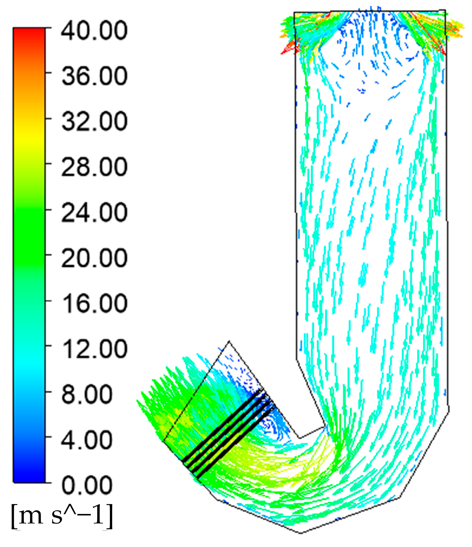
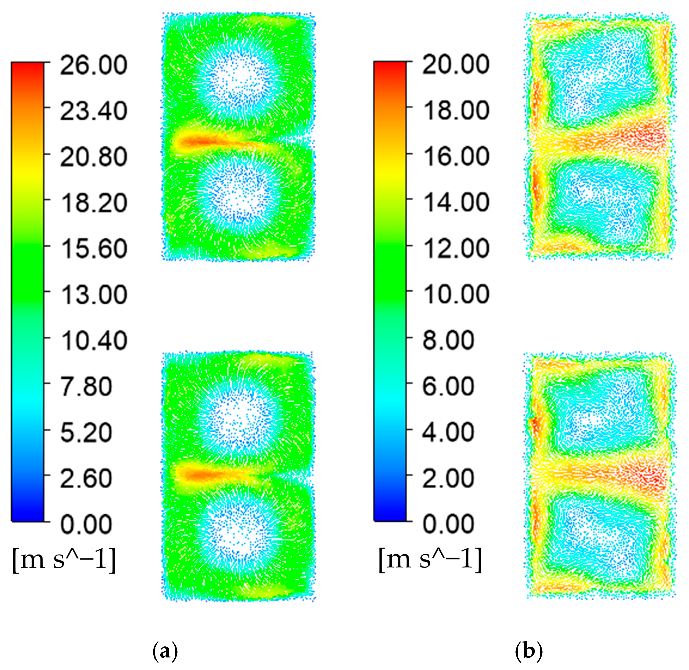
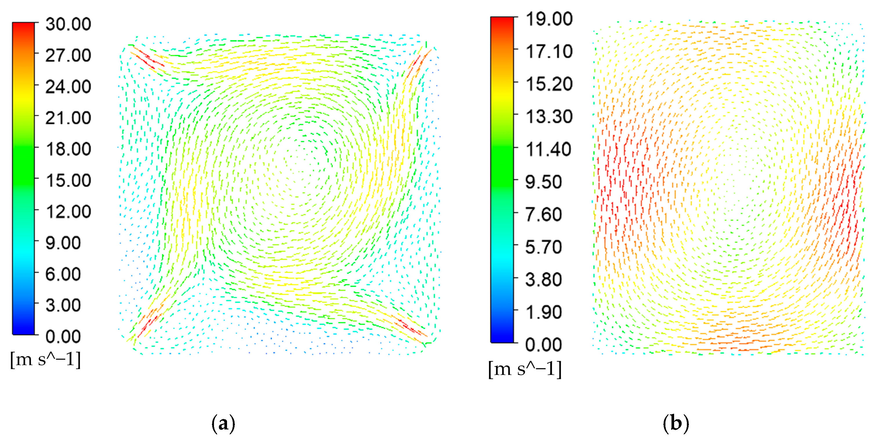
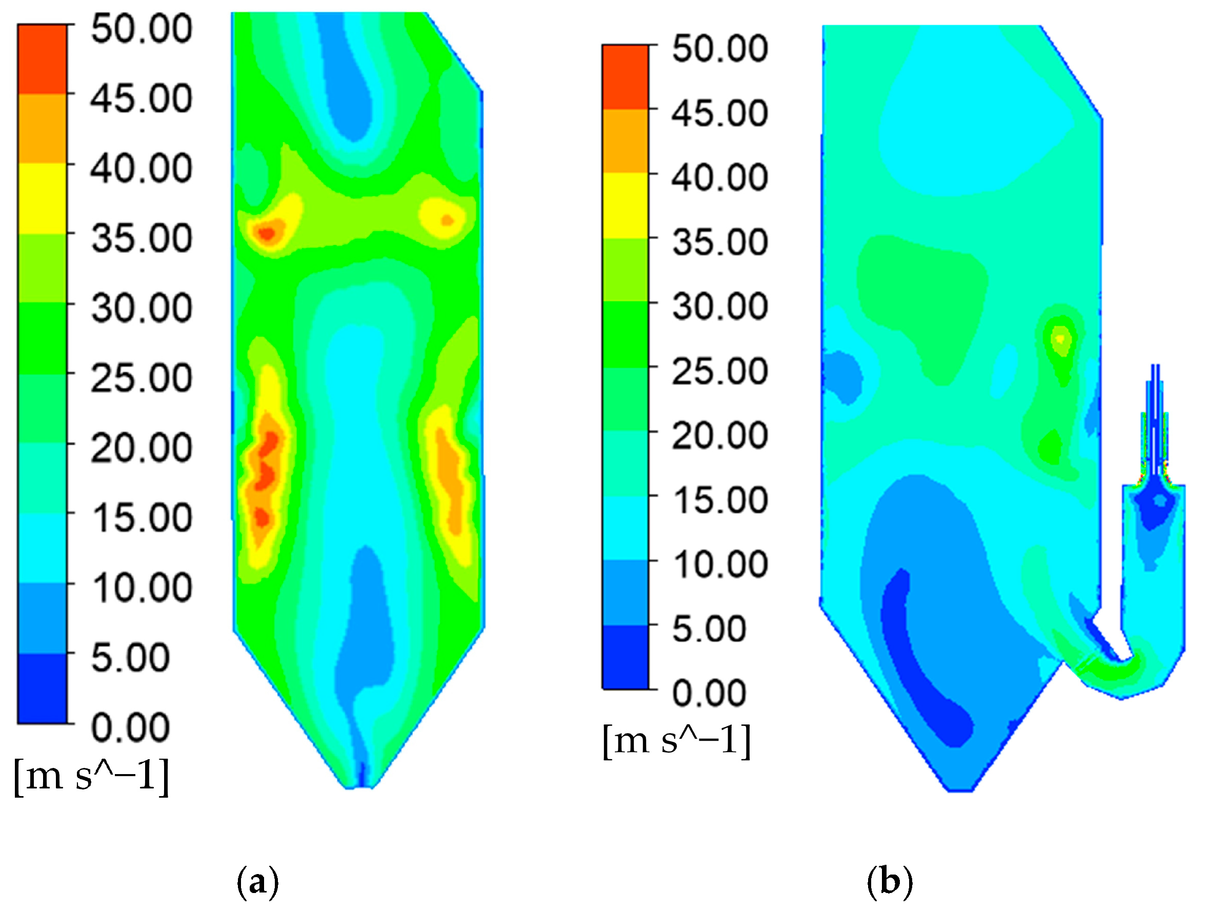
4.2. Analysis of the Aerodynamic Field in the Retrofit Furnace

Figure 5 presents the velocity vector distribution in the longitudinal section of the combustion chamber at y = 2.36 m, where the cyclone burner is located. The y = 0 m section is the center longitudinal section of the furnace chamber. In this region, near the exit of the cyclone burner, the airflow is influenced by the action of the cyclone vanes from the primary and secondary wind channels, which induce rotational flow. This results in a localized negative pressure area, leading to a recirculation phenomenon wherein part of the airflow moves upward [38]. Consequently, the combustion chamber is effectively filled with high-velocity gas flow, and the aerodynamic field is well distributed.
Figure 6 illustrates the velocity vector distributions at z = −6 m and z = −5 m. The z = 0 m section corresponds to the top of the ash hopper zone. In these sections, the secondary air enters tangentially, creating a high-velocity flow that forms a large vortex. The rotational flow at the exit of each cyclone burner aligns with the cyclone blades, and the adjacent cyclone burners rotate in opposite directions [39]. This arrangement promotes the thorough mixing of flue gas and pulverized coal particles, enhancing combustion efficiency and heat transfer, and improving the pulverized coal combustion rate. As the flue gas flows downstream, the cyclone region expands, although the intensity of the vortex weakens.
As depicted in Figure 7a, air is symmetrically injected from the center of each of the four corners at all levels. Due to the tangential combustion characteristics at these four corners, air and pulverized coal are introduced into the furnace chamber through four directional nozzles for combustion, with the flow directed horizontally at an angle of 43° relative to the furnace wall. The airflow exhibits a clockwise rotation; the velocity at the center of the furnace is low, while the peripheral air velocity is high, resulting in a rotating flow field that rises within the furnace.
Figure 7b exhibits the velocity vector distribution in the horizontal section at the bottom of the platen. Similar to a tangentially fired boiler [40], the intensity of the airflow rotation diminishes with increasing height within the chamber. However, despite the reduction in rotational intensity, residual airflow rotation persists, leading to deviations in the flue gas velocity profile at the furnace exit. This residual rotation may potentially disrupt the overall combustion process and affect the efficiency of downstream equipment.
The velocity distribution at the longitudinal section of the boiler before and after the retrofit at y = 2.36 m is depicted in Figure 8. For the pre-modification, tangentially fired furnace, the four directional airflows converge in the transverse central region of the hearth to form a tangential flow pattern. This interaction enhances the turbulence, promoting increased mixing and improving the flue gas filling performance within the hearth [40]. After the retrofit, the flue gas generated in the combustion chamber enters the furnace chamber at high velocity, inducing significant flow disturbances in the lower region of the furnace, particularly within the cold ash hopper area. These disturbances also influence the upper quadrangular tangential zone, impacting the overall flow dynamics within the furnace. In the middle section of the furnace, the flow velocity increases, due to the injection of primary and secondary air. In the upper section of the furnace, the combustion characteristics [41] of the four-corner tangential injection result in a lower velocity at the center of the furnace, while the velocity of the peripheral airflow is comparatively higher.
The stream line of pulverized coal particles entering the cyclone burner is illustrated in Figure 9. Similar to the double-U flame slag-tap boiler [42,43], the pulverized coal is introduced into the cyclone burner via the primary air inlet. Under the influence of the tangential secondary air, the pulverized coal particles are directed in a rotating pattern along the walls of the cyclone combustion chamber, thereby increasing their residence time within the burner [44]. The gas streams from different cyclone burners then mix, filling the combustion chamber with flue gas, while unburned coke particles are further entrained; this intensifies under the action of cyclone-generated gas flow until complete combustion is achieved.

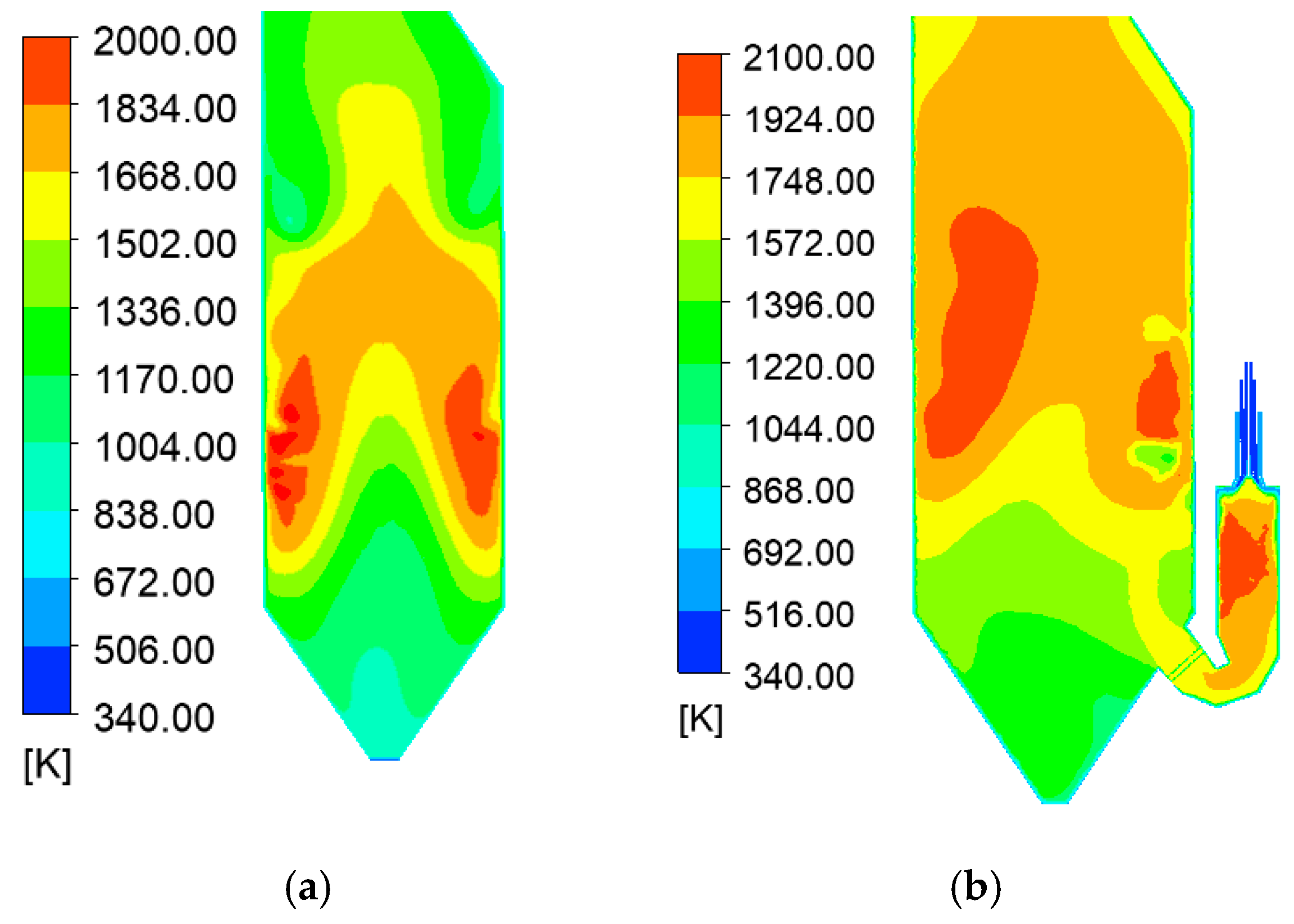
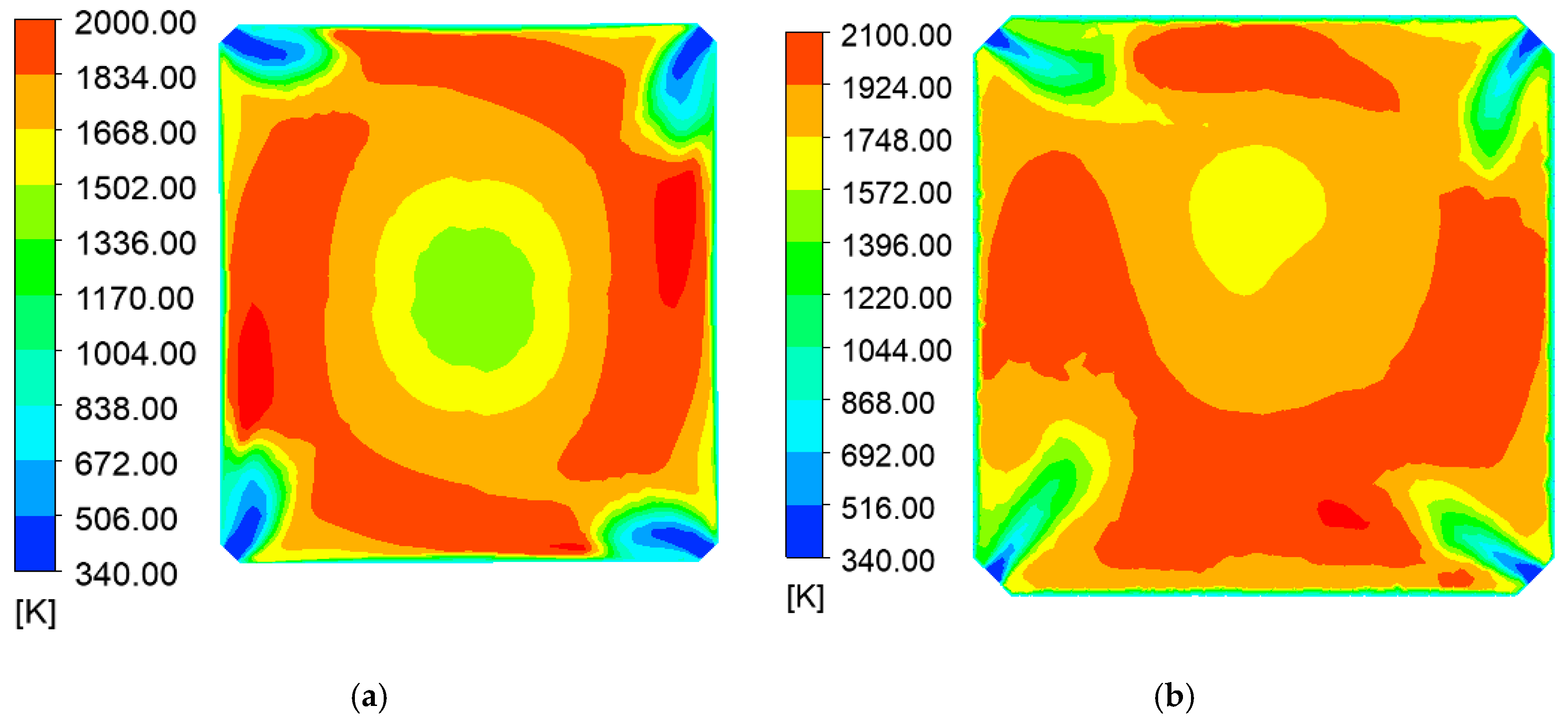
4.3. Analysis of the Temperature Field in the Retrofit Furnace

Figure 10 presents the temperature distribution along the longitudinal section of the boiler, before and after retrofit at y = 2.36 m. In the pre-modification, tangentially fired furnace design, the combustion heat release primarily occurs in the central transverse region of the furnace chamber, where the burner is located. Consequently, the temperature is higher in the middle and upper regions of the furnace, with a maximum recorded temperature of approximately 1995 K. After the retrofit, the highest temperature within the combustion chamber is located in the upper central region, with a peak temperature of approximately 2080 K in the middle of the combustion chamber. Due to the influence of the cyclone, the temperature distribution exhibits a pattern of higher values at the periphery and lower values at the center [45]. As the flue gas flows through the chamber, heat exchange between the flue gas and the furnace wall occurs, resulting in a gradual temperature reduction. At the combustion chamber exit, the flue gas temperature rapidly drops to around 1650 K, due to the presence of densely arranged slag traps.
In the lower part of the furnace, the temperature is higher on the right side, influenced by the jet flow from the combustion chamber exit, with the jet heat diffusing in the lower region of the burner. In the middle of the furnace, the temperature reaches a peak of about 2180 K, due to the combustion of pulverized coal, with a similar high-periphery, low-center temperature distribution [46]. Since the cross-section shown in Figure 10 is located on the positive half-axis of the Y-axis, and the tangential flow direction is clockwise, the temperature on the left side is notably higher than on the right side. As the flue gas rises, the temperature gradually decreases and becomes more uniform as the gases mix. In the bottom cross-section of the furnace, the average temperature of the flue gas is approximately 1700 K.
Figure 11 illustrates the temperature distribution at z = −9 m in the furnace before and after the retrofit. It is evident that in the burner exit region, the pulverized coal combusts rapidly under the influence of the four-corner tangential circular jets, leading to higher temperatures at the furnace periphery and relatively lower temperatures at the center [47]. This highlights the significant slagging challenges associated with burning high-alkali coal in a conventional tangentially fired boiler. On the one hand, flame tilting or an excessively large tangential circle can lead to tangential erosion of the water-cooled walls, facilitating the adhesion of molten particles and subsequent slag formation. On the other hand, the continuous movement of ash particles across densely arranged heating surfaces, such as the superheater and slag screen, further intensifies the risk of severe slagging.
In contrast, the slag-tap boiler exhibits a more concentrated combustion zone, resulting in a higher maximum combustion temperature of 2107 K. Unlike the tangential combustion boiler, the flue gas temperature near the water-cooled walls of the combustion chamber in the slagging boiler remains elevated. Additionally, the temperature near the ash hopper is significantly higher, causing ash particles to adhere to the furnace walls, flow downward, and exit the boiler in a molten state. This design effectively mitigates slagging issues by directing molten ash out of the system, thereby reducing its accumulation on critical heating surfaces.

4.4. Analysis of the Component Concentrations in the Retrofit Furnace

Figure 12a illustrates the O2 mass fraction distribution along the longitudinal section of the boiler at y = 2.36 m. The O2 mass fraction follows a similar pattern in both the combustion chamber and the furnace. In the combustion chamber, the O2 mass fraction decreases rapidly at the burner nozzle, indicating the rapid progression of the combustion reaction. In the central region, O2 is consumed more quickly due to the lower flow rate [42,48,49]. The remaining O2 adheres to the furnace wall and flows into the furnace chamber with the flue gas. In the furnace chamber, the O2 from the combustion chamber is largely depleted by the time it reaches the cross-section of the lowest burner. Oxygen entering from the hearth is also rapidly consumed in the burner region, with the residual oxygen primarily concentrated in the central part of the hearth. Analysis of the velocity and temperature fields reveals that the center of the hearth contains less pulverized coal and exhibits a lower temperature, which leads to a reduced reaction rate.
Figure 12b presents the CO2 mass fraction distribution along the same longitudinal section of the furnace at y = 2.36 m. As demonstrated in the figure, the CO2 mass fraction increases steadily throughout the combustion process [36,37]. A rapid rise in CO2 content is observed in the burner outlet regions of both the furnace chamber and the combustion chamber, with the CO2 concentration continuing to increase as the combustion reaction progresses.

4.5. Influence of the Zhundong Coal Ratio on Heat and Mass Transfer Characteristics in the Furnace

Figure 13 illustrates the velocity distribution within the furnace for the combustion ratios of Zhundong coal at 20%, 25%, and 30%. As the proportion of Zhundong coal in the combustion process increases, the air distribution within the furnace chamber decreases. This leads to a reduction in flow velocity in the upper and middle sections of the furnace, accompanied by a reduction in the intensity of the cyclonic flow. Simultaneously, the air distribution in the combustion chamber increases, with a notable increase of approximately 50%. This adjustment notably influences the flow field within the furnace, particularly affecting the exit jet from the combustion chamber, as described in previous studies [8,9,10,11]. At a combustion ratio of 30% Zhundong coal, the exit jet exhibits increased penetration within the furnace, significantly disrupting the quadrangular tangential flow near the bottom burner.
The temperature distribution in the furnace when the combustion ratio of Zhundong coal is 20%, 25%, and 30% is demonstrated in Figure 14. With increasing proportions of Zhundong coal, the temperature within the main furnace chamber decreases, primarily due to reduced coal feed to the burners. In contrast, the temperature in the combustion chamber increases. At a 30% Zhundong coal ratio, the exit jet’s disturbance has a pronounced impact on the internal flow dynamics within the furnace [15,16], displacing coal dust from the right side of the bottom burner toward the center of the furnace chamber. This shift forms a low-temperature zone on the right side of the bottom burner and creates a high-temperature zone in the central region. At a 30% Zhundong coal ratio, the combustion chamber temperature rises by approximately 3%, reaching around 2080 K, while the flow velocity in the upper and middle furnace sections decreases by up to 15%, effectively enhancing the overall combustion intensity.
The mass fraction distributions of O2 and CO2 within the furnace for Zhundong coal combustion ratios of 20%, 25%, and 30% are presented in Figure 15 and Figure 16, respectively. As depicted in Figure 15, the overall trend of O2 distribution within the combustion chamber remains largely consistent as the combustion ratio of Zhundong coal increases. However, the intensified disturbance of the furnace flow field caused by the exit jet from the combustion chamber significantly raises the oxygen concentration on the right side of the bottom burner region [42,48,50]. An integrated analysis of the velocity and temperature field distributions further reveals that this disturbance notably suppresses the combustion reaction rate in the affected region, highlighting the jet’s influence on the local combustion dynamics.
Figure 16 illustrates the CO2 mass fraction distribution under the same working conditions. Unlike the O2 distribution in Figure 15, the CO2 concentration on the right side of the bottom burner region increases markedly with a higher excess air coefficient [36,37,42]. This observation further confirms that the reduced combustion intensity in this region is closely linked to changes in the flow field, which are driven by the disturbance from the combustion chamber’s exit jet.

5. Conclusions

In this study, a semi-industrial retrofit is investigated for a tangentially fired boiler through the integration of a slag-tap chamber. CFD simulations are employed to analyze the effects of this modification on the combustion characteristics of high-alkali Zhundong coal, as well as the influence of coal blending ratios on heat and mass transfer characteristics within the furnace. The primary conclusions are as follows:
  • The combustion chamber exhibits a peak temperature of approximately 2080 K in the upper central region, with a peripheral-to-center gradient driven by cyclonic flow. As the flue gas exits, the temperature drops to around 1650 K, due to the slag catcher’s cooling. Meanwhile, furnace regions reach a peak temperature of 2180 K during coal combustion, displaying a periphery–high, center–low temperature distribution. This modification significantly stabilizes combustion and reduces slag formation. These findings demonstrate the retrofit’s potential to improve operational reliability when burning high-alkali coal.
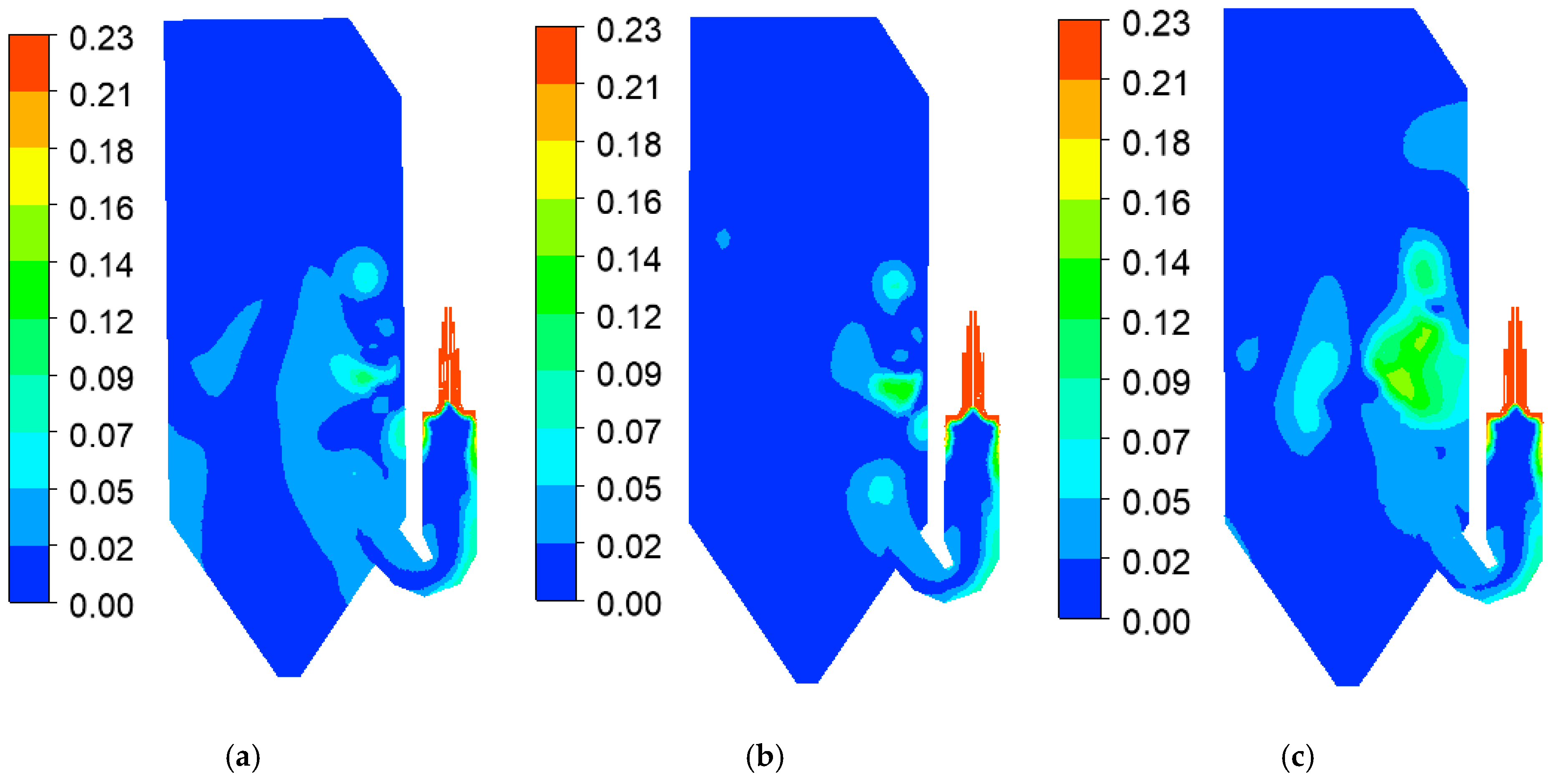
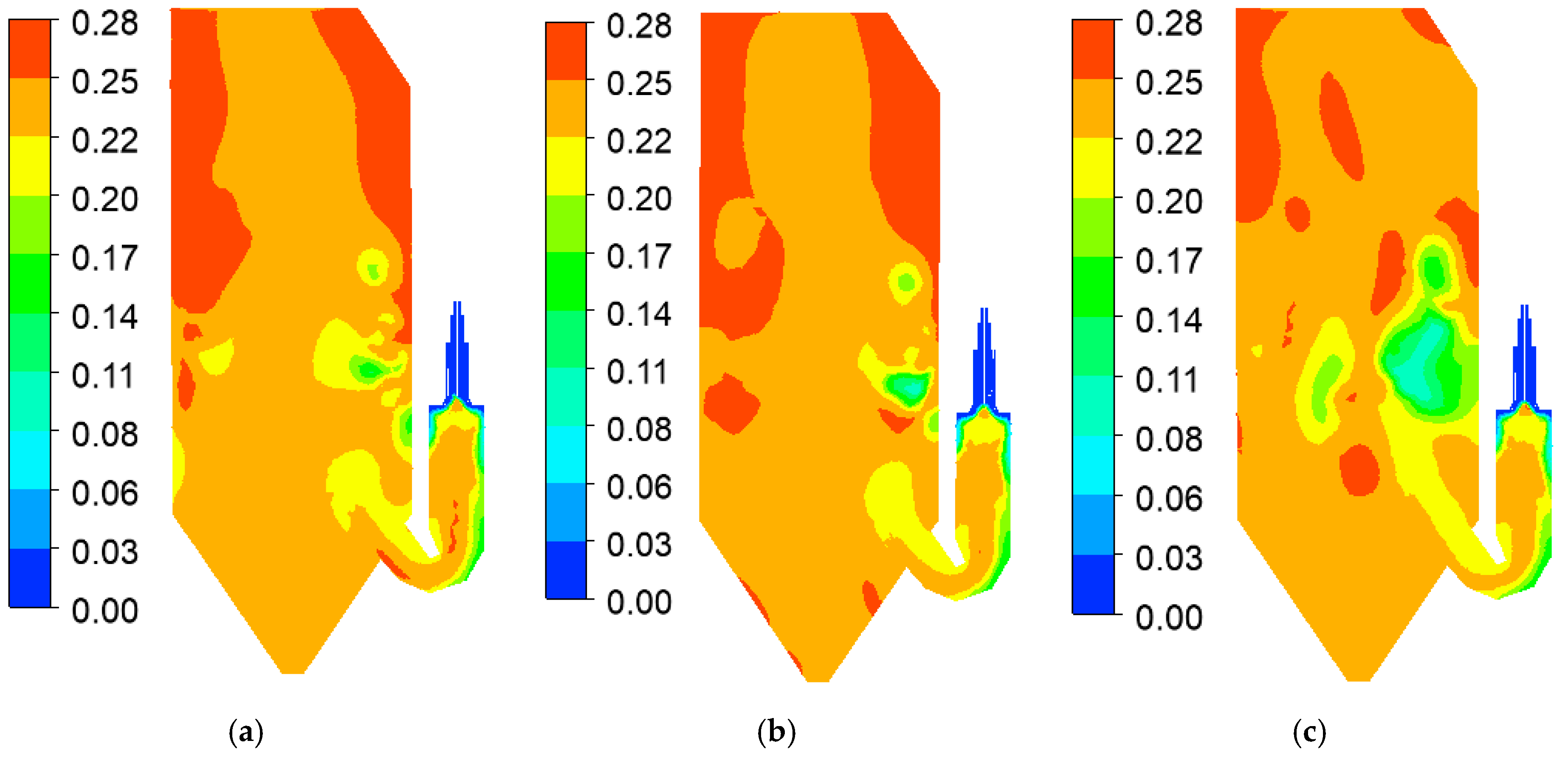
  • The retrofit effectively regulates O2 and CO2 distributions throughout the furnace, enhancing oxygen availability and CO2 formation in critical regions. This optimization improves the combustion efficiency and reduces the risk of slagging. Such improvements are critical for industrial applications where high combustion efficiency and reduced fouling are key operational objectives.
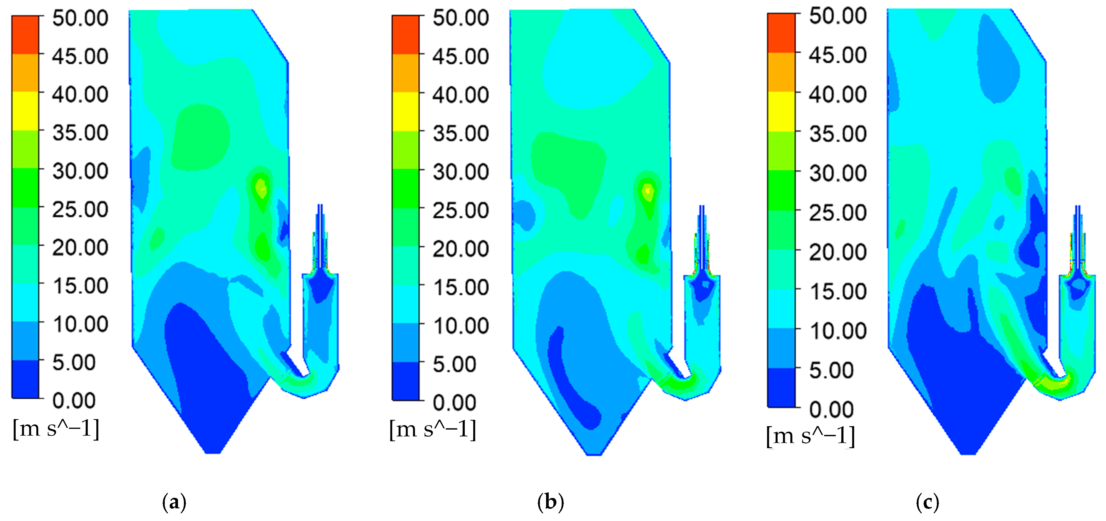
  • Higher blending ratios of Zhundong coal induce specific shifts in O2 and CO2 concentrations, particularly near the bottom burner region, indicating improved air–fuel mixing, facilitated by the retrofit. As the Zhundong coal ratio increases to 30%, the combustion chamber temperature rises by 3%, reaching approximately 2080 K, while the flow velocity in the upper and middle furnace sections decreases by up to 15%, thereby enhancing the overall combustion intensity. From an engineering perspective, this finding supports the adaptability of the retrofit for various coal blending scenarios, which is crucial for operational flexibility.
  • The temperature distribution within the furnace displays higher values at the periphery, with a peak temperature of around 2180 K in the combustion chamber center, aligning with cyclone combustion characteristics. Additionally, the O2 and CO2 mass fraction distributions confirm that the retrofit effectively manages oxygen consumption and combustion product formation, with notable changes in concentrations influenced by disturbances from the combustion chamber’s exit jet.
  • Higher blending ratios reduce the flow velocity in the upper and middle furnace sections, thereby decreasing cyclonic flow intensity. However, the exit jet from the combustion chamber significantly impacts flow dynamics, causing local temperature fluctuations of ± 5% that ultimately influence combustion efficiency. Addressing these dynamics in future designs could further optimize furnace performance.
The findings of this study highlight significant industrial implications, demonstrating that integrating a slag-tap chamber into existing tangentially fired boilers offers an economical and practical solution for efficiently utilizing high-alkali coals like Zhundong coal. This retrofit enhances combustion stability and efficiency, reduces operational costs, and mitigates environmental impacts such as slag-related maintenance and particulate emissions. To further validate these findings, future work should focus on experimental validation through pilot-scale tests, long-term performance assessment using varying coal compositions, and economic and environmental analyses. Additionally, optimization studies on design modifications, such as secondary air distribution and slag-tap chamber dimensions, will provide deeper insights and promote the industrial adoption of this technology.

Author Contributions

Conceptualization, Q.W. and F.F.; methodology, Q.W. and J.G.; validation, J.G. and L.Z.; formal analysis, Y.C.; investigation, Y.C. and L.D.; resources, L.D.; data curation, F.F.; writing—original draft preparation, Q.W.; writing—review and editing, F.F. and Y.C.; supervision, J.G.; project administration, L.D.; funding acquisition, J.G. and L.Z. All authors have read and agreed to the published version of the manuscript.

Funding

This research was funded by the project “Key Technology Development and Semi-Industrial Verification of a Slag-tap Boiler for High-Alkaline Coal in Xinjiang” (Grant No. HNKJ21-H70).

Data Availability Statement

The data presented in this study are available on request from the corresponding author. The data are not publicly available, due to privacy.

Conflicts of Interest

Authors Qinglong and Wu Fan Fang were employed by the company Xi’an Thermal Power Research Institute Co., Ltd. Authors Jingyu Guan and Lingkun Zhu were employed by the company Harbin Boiler Co., Ltd. The remaining authors declare that the research was conducted in the absence of any commercial or financial relationships that could be construed as a potential conflict of interest.

References

  1. Li, X.; Li, J.; Wu, G.G.; Bai, Z.Q.; Li, W. Clean and efficient utilization of sodium-rich Zhundong coals in China: Behaviors of sodium species during thermal conversion processes. Fuel 2018, 218, 162–173. [Google Scholar] [CrossRef]
  2. Lei, Y.; Fu, P.; Tang, S.; Yue, F.; Bie, K.; Liu, Y. Occurrence form of sodium in Zhundong coal and its evaporation and condensation characteristics. J. Combust. Sci. Technol. 2019, 25, 124–130. [Google Scholar]
  3. Wang, C.A.; Li, G.Y.; Du, Y.B.; Yan, Y.; Li, H.; Che, D.F. Ash deposition and sodium migration behaviors during combustion of Zhundong coals in a drop tube furnace. J. Energy Inst. 2018, 91, 251–261. [Google Scholar] [CrossRef]
  4. Jing, X.H.; Pu, Y.; Li, Z.Y.; Tang, Q.L.; Yao, B.; Fu, P.F.; Lou, C.; Lim, M. Experimental Investigation of Gaseous Sodium Release in Slag-Tapping Coal-Fired Furnaces by Spontaneous Emission Spectroscopy. Energies 2022, 15, 4165. [Google Scholar] [CrossRef]
  5. Hariana; Prismantoko, A.; Prabowo; Hilmawan, E.; Darmawan, A.; Aziz, M. Effectiveness of different additives on slagging and fouling tendencies of blended coal. J. Energy Inst. 2023, 107, 101192. [Google Scholar] [CrossRef]
  6. Zhu, L. Analysis and optimization of high alkali coal boiler. Boil. Technol. 2020, 51, 37–44. [Google Scholar]
  7. Guo, Y.; Bai, X.; Zhang, X.; Gao, G.; Wang, G.; Yao, W. Study on techniques for slagging prevention and ash deposition control in existing boilers burning high-alkali coal. Therm. Power Gener. 2022, 51, 131–140. [Google Scholar]
  8. Zhang, P.; Lyu, J.; Wang, H.; Xin, S.; Liang, J.; Wu, W.; Qiu, Z.; Du, J. Study kaolin on operation characteristics of a 300 MW CFB boiler burning Zhundong high-alkali coal. Boil. Technol. 2020, 51, 29–32+54. [Google Scholar]
  9. Yang, Y.; Wang, D.; Chen, X.; Yao, B. Study on comprehensive evaluation of slagging characteristics of high-alkali coal blending combustion from Hami Area. Coal Sci. Technol. 2020, 48, 207–213. [Google Scholar]
  10. Yang, Y.; Chen, C.; Chen, X.; Wang, D.; Yao, B. Experimental study on fouling characteristics for blending ratio of high alkali coal in Hami area. Coal Sci. Technol. 2019, 47, 214–219. [Google Scholar]
  11. Meng, Y.; Li, Y.; Yang, Z.; Qi, Q.; Jiang, T.; Zhao, X.; Nie, M. Adaptability research of different types of boiler burning Naomaohu high-alkali coal in one power plant. Therm. Power Gener. 2023, 52, 142–149. [Google Scholar]
  12. Huang, S.; Zhang, L.; Yan, J.; Wang, Z.; Lei, Z.; Li, Z.; Ren, S.; Wang, Z.; Shui, H. Investigation on cofiring high-alkali coal with coal gangues: SO2, NO reduction and ash slagging inhibition. CIESC J. 2022, 73, 5581–5591. [Google Scholar]
  13. Wang, Y.A.; Zou, L.; Shao, H.S.; Bai, Y.Y.; Liu, Y.; Zhao, Q.X.; Li, F.X. Co-combustion of high alkali coal with municipal sludge: Thermal behaviour, kinetic analysis, and micro characteristic. Sci. Total Environ. 2022, 838, 156489. [Google Scholar] [CrossRef] [PubMed]
  14. Li, Y.D.; Yang, D.; Zhou, X.H.; Dong, L.; Suo, L.H.; Sun, W.B. Heavy metal migration characteristics of co-combustion between sewage sludge and high alkaline coal on circulating fluidized bed. J. Therm. Sci. 2022, 31, 2178–2188. [Google Scholar] [CrossRef]
  15. Tang, C.W.; Pan, W.G.; Zhang, J.K.; Wang, W.H.; Sun, X.L. A comprehensive review on efficient utilization methods of High-alkali coals combustion in boilers. Fuel 2022, 316, 123269. [Google Scholar] [CrossRef]
  16. Liu, Y.Q.; Cheng, L.M.; Ji, J.Q.; Zhang, W.G. Ash deposition behavior in co-combusting high-alkali coal and bituminous coal in a circulating fluidized bed. Appl. Therm. Eng. 2019, 149, 520–527. [Google Scholar] [CrossRef]
  17. Wang, Y.G.; Bai, Y.Y.; Zou, L.; Liu, Y.; Li, F.X.; Zhao, Q.X. Co-combustion characteristics and ash melting behavior of sludge/high-alkali coal blends. Combust. Sci. Technol. 2024, 196, 177–194. [Google Scholar] [CrossRef]
  18. Wu, Q.; Hu, S.; Liu, J.; Zhang, Y.; Li, H.; Zhou, H. Slagging and element migration characteristics of Zhundong coal in horizontal liquid slag cyclone furnace. Clean Coal Technol. 2024, 30, 27–35. [Google Scholar]
  19. Gong, Y.; Fu, P.; Liu, Y.; Bie, K. Sintering characteristics of Zhundong coal ash and refractory material of slag tap pulverized coal boiler. J. Combust. Sci. Technol. 2021, 27, 67–73. [Google Scholar]
  20. Ren, Z.; Fan, J.; Chen, S. Numerical simulation of combustion characteristics of horizontal cyclone burner. Power Syst. Eng. 2021, 37, 25–28+32. [Google Scholar]
  21. Lan, D.; Fan, J.; Zhang, Z.; Hu, X.; Chen, S. Experimental study on combustion of high alkali coal in horizontal liquid slag cyclone furnace. Clean Coal Technol. 2020, 26, 119–126. [Google Scholar]
  22. Hu, S.H.; Ni, Y.G.; Yin, Q.; Wang, J.K.; Lv, L.Q.; Cen, K.F.; Zhou, H. Research on element migration and ash deposition characteristics of high-alkali coal in horizontal liquid slagging cyclone furnace. Fuel 2022, 308, 121962. [Google Scholar] [CrossRef]
  23. Zhu, M.X.; Lu, H.; Zhao, W.J.; Huang, S.W.; Chang, X.Q.; Dong, L.J.; Kong, D.; Jing, X.H. A numerical study of ash deposition characteristics in a 660MW supercritical tangential boiler. Adv. Theory Simul. 2023, 6, 2300133. [Google Scholar] [CrossRef]
  24. Zhong, Y.X.; Wang, X.; Xu, G.; Ning, X.Y.; Zhou, L.; Tang, W.; Wang, M.H.; Wang, T.; Xu, J.; Jiang, L.; et al. Investigation on slagging and high-temperature corrosion prevention and control of a 1000 MW ultra supercritical double tangentially fired boiler. Energy 2023, 275, 127455. [Google Scholar] [CrossRef]
  25. Liao, X.; Zhang, Q.; Yang, W.H.; Qiu, Z.Z.; Guo, R.T.; Liu, J.Q.; Li, F.Q.; Li, Y. The role of pulverized coal drying temperature in fly ash carbon content and slagging of a tangentially coal-fired boiler. Fuel 2019, 257, 115951. [Google Scholar] [CrossRef]
  26. Pei, J.J.; Zhang, Z.; You, C.F. Optimizing the combustion of low-quality coal by the wall wind auxiliary combustion method in a tangentially fired utility boiler. Combust. Sci. Technol. 2019, 191, 570–589. [Google Scholar] [CrossRef]
  27. ASTM D388-19; Standard Classification of Coals by Rank. ASTM International: West Conshohocken, PA, USA, 2019.
  28. GB/T 5751-2009; Classification of Coals in China. National Standard of the People’s Republic of China: Beijing, China, 2009.
  29. Wang, H.; Ma, X.; Deng, L.; Bai, P.; Wang, Y. Double-U-Shaped Low-Nitrogen Combustion System of Liquid Slag Discharging Boiler Containing Classified Furnace Smoke. CN112325276A, 5 February 2021. [Google Scholar]
  30. Hidki, R.; El Moutaouakil, L.; Boukendil, M.; Charqui, Z.; Jamal, B. Analysis of mixed convection and surface radiation in a horizontal channel containing different finned heat-generating blocks. Therm. Sci. Eng. Prog. 2024, 48, 102370. [Google Scholar] [CrossRef]
  31. Ma, Q.L.; Zhong, W.Q.; Chen, X.; Li, J.H.; Zhang, H. Numerical Simulation of the Effects of Oil Gun Location and Oil Feed Rate on Coal Ignition and Burner Wall Temperature in a Tiny Oil Ignition Burner. Energies 2021, 14, 7597. [Google Scholar] [CrossRef]
  32. Rachele, L.; Cristiana, B.; Marco, F.; Leonardo, T.; Chiara, G. Impact of H2-enriched natural gas on pollutant emissions from domestic condensing boilers: Numerical simulations of the combustion chamber. Int. J. Hydrog. Energy 2023, 48, 19686–19699. [Google Scholar]
  33. Nakamura, H.; Zhang, J.W.; Hirose, K.; Shimoyama, K.; Ito, T.; Kanaumi, T. Generating simplified ammonia reaction model using genetic algorithm and its integration into numerical combustion simulation of 1 MW test facility. Appl. Energy Combust. Sci. 2023, 15, 100187. [Google Scholar] [CrossRef]
  34. Zhu, B.; Shang, B.C.; Guo, X.; Wu, C.; Chen, X.Q.; Zhao, L.L. Study on Combustion Characteristics and NOx Formation in 600 MW Coal-Fired Boiler Based on Numerical Simulation. Energies 2023, 16, 262. [Google Scholar] [CrossRef]
  35. Li, Z.X.; Miao, Z.Q.; Shen, X.S.; Li, J.T. Effects of momentum ratio and velocity difference on combustion performance in lignite-fired pulverized boiler. Energy 2018, 165, 825–839. [Google Scholar] [CrossRef]
  36. Zhu, M.; Chen, L.; Zhou, L.A.; Jiang, L.; Su, S.; Hu, S.; Xu, K.; Wang, C.; Li, A.S.; Qing, H.R.; et al. Experimental test, numerical analysis and thermal calculation modeling of hundreds kWth-class supercritical CO2 fossil-fired boiler system. Energy 2023, 284, 128523. [Google Scholar] [CrossRef]
  37. Zhou, J.; Zhu, M.; Su, S.; Chen, L.; Xu, J.; Hu, S.; Wang, Y.; Jiang, L.; Zhong, W.Q.; Xiang, J. Numerical analysis and modified thermodynamic calculation methods for the furnace in the 1000 MW supercritical CO2 coal-fired boiler. Energy 2020, 212, 118735. [Google Scholar] [CrossRef]
  38. Wang, W.S.; Sun, Y.Z.; Huang, Z.H.; Liao, Y.H.; Fang, F. Numerical simulation of NOx emission characteristics of a cyclone boiler with slag-tap furnace. Acs Omega 2020, 5, 29978–29987. [Google Scholar] [CrossRef]
  39. Li, X.Y.; Li, G.Y.; Cao, Z.D.; Xu, S.S. Research on flow characteristics of slag film in a slag tapping gasifier. Energy Fuels 2010, 24, 5109–5115. [Google Scholar] [CrossRef]
  40. Karampinis, E.; Nikolopoulos, N.; Nikolopoulos, A.; Grammelis, P.; Kakaras, E. Numerical investigation Greek lignite/cardoon co-firing in a tangentially fired furnace. Appl. Energy 2012, 97, 514–524. [Google Scholar] [CrossRef]
  41. Chen, S.N.; He, B.S.; He, D.; Cao, Y.; Ding, G.C.; Liu, X.; Duan, Z.P.; Zhang, X.; Song, J.G.; Li, X.Z. Numerical investigations on different tangential arrangements of burners for a 600 MW utility boiler. Energy 2017, 122, 287–300. [Google Scholar] [CrossRef]
  42. Wang, W.; Huang, Z.; Fang, F.; Liao, Y. Effect of primary air blade inclination angle on combustion and NOx emission of a cyclone boiler with slag-tap furnace. J. Chin. Soc. Power Eng. 2021, 41, 8–13. [Google Scholar] [CrossRef]
  43. Yang, J.; Wang, J.; Ma, X.; Deng, L.; Da, Y.; Che, D. Thermal calculation and numerical simulation on double-U flame slag-tap boiler that fully burning high-alkali coal. Therm. Power Gener. 2024, 53, 38–45. [Google Scholar]
  44. Ran, J.; Liu, L.; Li, C. Study on combustion and deposition characteristics of coal particles in a cyclone burner. J. Power Eng. 2012, 32, 836–840. [Google Scholar]
  45. Zhu, T.; Tang, C.L.; Ning, X.; Wang, L.M.; Deng, L.; Che, D.F. Experimental study on NOx emission characteristics of Zhundong coal in cyclone furnace. Fuel 2022, 311, 122536. [Google Scholar] [CrossRef]
  46. Qin, S.; Du, J.; Li, C.; Zhou, Y. Numerical investigations on the aerodynamics and flue gas recirculation optimization of cyclone-fired coal boiler. Therm. Power Gener. 2024, 53, 53–63. [Google Scholar]
  47. You, M.; Chen, L.; Shang, Y.; Gao, A.; Su, S.; Xiang, J. Low load combustion characteristics of supercritical wall type tangentially fired boiler. Clean Coal Technol. 2023, 29, 145–152. [Google Scholar]
  48. Xu, C.; Shao, Y.; Lu, P.; Song, T. Numerical simulation of low NOx swirl combustor with inverse diffusion flame. J. Eng. Therm. Energy Power 2023, 38, 170–178. [Google Scholar]
  49. Wang, W.; Luo, X.; Yang, Z.; Liao, Y. Effect of excess air coefficient on combustion and NOx emission of cyclone boiler with pure high alkali coal. J. Eng. Therm. Energy Power 2021, 36, 73–79. [Google Scholar]
  50. Lv, H.; Tong, J.; Qi, X.; Hua, G. Numerical simulation on air flow distribution characteristics for 1 000 MW swirl burners. J. Eng. Therm. Energy Power 2017, 32, 86–90. [Google Scholar]
Figure 1. The structures of the tangentially fired boiler and its burners. (a) Boiler; (b) burners; (c) boiler geometry.
Energies 17 06331 g001
Figure 2. The (a) front view and (b) top view of the slag-tap boiler and its geometry structures. (a) Front view; (b) top view; (c) boiler geometry.
Energies 17 06331 g002
Figure 3. Grid diagram. (a) Front view; (b) right view.
Energies 17 06331 g003
Figure 4. Temperature distribution in the height direction with different numbers of grid cells.
Energies 17 06331 g004
Figure 5. The velocity vector in the y = 2.36 m section of the combustion chamber.
Energies 17 06331 g005
Figure 6. The velocity vector in the horizontal section of the combustion chamber: (a) z = −6 m; (b) z = −5 m.
Energies 17 06331 g006
Figure 7. The velocity vector in the horizontal section of the furnace chamber: (a) z = −10 m; (b) z = −29 m.
Energies 17 06331 g007
Figure 8. The velocity distribution in the y = 2.36 m section before and after the retrofit. (a) Before retrofit; (b) after retrofit.
Energies 17 06331 g008
Figure 9. The stream line in the cyclone burner.
Energies 17 06331 g009
Figure 10. The temperature distribution in the y = 2.36 m section before and after the retrofit. (a) Before retrofit; (b) after retrofit.
Energies 17 06331 g010
Figure 11. The temperature distribution in the z = −9 m section before and after the retrofit. (a) Before retrofit; (b) after retrofit.
Energies 17 06331 g011
Figure 12. The mass fraction distribution of air components in the y = 2.36 m section in the furnace chamber: (a) O2; (b) CO2.
Energies 17 06331 g012
Figure 13. The velocity distribution in the furnace chamber with different Zhundong coal ratios: (a) 20%; (b) 25%; (c) 30%.
Energies 17 06331 g013
Figure 14. The temperature distribution in the furnace chamber with different Zhundong coal ratios: (a) 20%; (b) 25%; (c) 30%.
Energies 17 06331 g014
Figure 15. The mass fraction distribution of O2 in the furnace chamber with different Zhundong coal ratios: (a) 20%; (b) 25%; (c) 30%.
Energies 17 06331 g015
Figure 16. The mass fraction distribution of CO2 in the furnace chamber with different Zhundong coal ratios: (a) 20%; (b) 25%; (c) 30%.
Energies 17 06331 g016
Table 1. Design parameters of the tangentially fired boiler.
ParameterSuperheated Steam Flow Rate (t h−1)Superheated Steam Temperature (K)Superheated Steam Pressure (MPa)Feed Water Temperature (K)Reheated Steam Flow Rate (t h−1)Excess Air Ratio
Value1025.0814.017.5555.3846.11.25
Table 2. Fuel property analysis of the coal under study.
Proximate Analysis (%)Ultimate Analysis (%)Qnet,ar
(MJ⋅kg−1)
MarAarVdafFCarCarHarOarNarSar
18.4015.8923.0242.6951.932.659.590.560.9819.98
Note: Mar: Moisture content on an as-received basis (%); Aar: ash content on an as-received basis (%); Vdaf: volatile matter on a dry and ash-free basis (%); FCar: fixed carbon on an as-received basis (%); Car: carbon content on an as-received basis (%); Har: hydrogen content on an as-received basis (%); Oar: oxygen content on an as-received basis (%); Nar: nitrogen content on an as-received basis (%); Sar: sulfur content on an as-received basis (%); Qnet,ar: lower heating value on an as-received basis (MJ⋅kg−1).
Table 3. The operating conditions in the numerical simulation.
ParametersBoundary Conditions
InletMass flow rate
OutletOutflow
Wall motionStationary wall
Wall shear conditionNo slip
Wall thermal conditionIsothermal
Table 4. Fuel property analysis of the Zhundong coal.
Proximate Analysis (%)Ultimate Analysis (%)Qnet,ar
(MJ⋅kg−1)
MarAarVdafFCarCarHarOarNarSar
22.6011.0230.1536.2350.463.3211.460.670.4718.80
Table 5. Coal blending ratios under different working conditions.
Working Conditions123
Coal blending ratios (%)202530
Table 6. Comparison of the thermal calculation and numerical simulation results.
ParameterThermal Calculation ResultsCFD Results
Maximum combustion temperature (K)2193.22224.7
Gas temperature at the bottom of the platen (K)1438.41468.5
Disclaimer/Publisher’s Note: The statements, opinions and data contained in all publications are solely those of the individual author(s) and contributor(s) and not of MDPI and/or the editor(s). MDPI and/or the editor(s) disclaim responsibility for any injury to people or property resulting from any ideas, methods, instructions or products referred to in the content.

