Article

Oil Cooling Method for Internal Heat Sources in the Outer Rotor Hub Motor of ElectricVehicle and Thermal Characteristics Research

1
Automotive Academy, Guangdong Mechanical and Electrical Polytechnic, Guangcong No. 9 Road, Baiyun District, Guangzhou 510550, China
2
National Engineering Laboratory for Electric Vehicles, Beijing Institute of Technology, No. 5 South Zhongguancun Street, Haidian District, Beijing 100081, China
*
Author to whom correspondence should be addressed.
Energies 2024, 17(24), 6312; https://doi.org/10.3390/en17246312
Submission received: 11 September 2024 / Revised: 5 December 2024 / Accepted: 7 December 2024 / Published: 14 December 2024
(This article belongs to the Section E: Electric Vehicles)

Abstract

:
The heat dissipation of wheel hub motors is difficult due to the limited installation space and harsh working environment, which will lead to an increase in the operating temperature of the motor. Excessive motor temperature will limit the further increase in the power density and torque density of the motor. Taking the outer rotor hub motor as the research object, a heat dissipation structure is designed by passing oil through the stator core, slot wedge, and the motor end, mainly the cooling stator core, slot winding, and the end winding from inside of the motor. The internal heat is mainly carried away through lubricating oil by convective heat transfer and heat conduction. The heat distribution model of the motor based on the new cooling structure is established using the centralized parameter heat network method. The Motor-CAD software is used to build the motor 3d model and simulate the motor temperature field, and the temperature distribution in the motor under the rated working condition is analyzed. The temperature rising test of the motor prototype are performed on a bench built in the laboratory. The experimental results are consistent with the simulation results of the temperature field, which verify the rationality of the model.

1. Introduction

Hub motors must have high power density and high thermal load due to the limitation of usage and installation space. When the temperature exceeds the heat resistance grade of the copper wire of the motor, the motor efficiency and service life are lightly affected, and cause an accident by heavily burning the motor because of the poor cooling conditions. In addition, the performance of the permanent magnets and winding resistance are closely related to the temperature. When the temperature of the motor increases, the demagnetization of the permanent magnet weakens the magnetic field, increases the working current, and increases the copper consumption, which will aggravate the demagnetization of the permanent magnet. Therefore, the cooling structure and thermal characteristics of the motor must be studied in detail [1,2].
Early oil immersion cooling of the motor stator and rotor resulted in an average cooling effect and energy loss due to oil agitation. After adopting the water jacket cooling method, Zhou Zhigang found that the maximum temperature drop of the inner rotor motor components was greater than that of the outer rotor motor, and the maximum temperature of the outer rotor hub motor components was 78.4 °C, which is 41 °C lower than the winding temperature during natural cooling [3]. CHAI Xiaohui uses water to cool the stator winding and found that increasing the inner diameter of the water channel can achieve better cooling effects under the same motor operating conditions and coolant flow rate [4]. Liu Zhuo proposed a method in which 36 U-shaped water channels are evenly distributed on the stator of the motor, and each water channel is connected through a neat U-shaped water outlet. This U-shaped structure not only connects the water pipes in each axis, but also takes into account the heat dissipation of the end winding of the wheel hub motor. The temperature rise of the internal end winding of the motor is reduced by 28.7% [5]. Li Ye wrapped the motor end winding with an ultra-thin glass fiber shell and directly cooled it with cooling oil, reducing the average temperature of the motor end winding by 40% [6,7,8,9,10]. Pia M Lindh uses stainless steel cooling pipes to directly cool the stator core inside the dual stator motor. Compared with indirect cooling methods, the stator temperature is reduced by about 50 °C [11,12,13]. Motor losses are mainly concentrated in the windings and core, so it is necessary to design the cooling structure to make the oil as close as possible to the heat source to improve the cooling effect [14,15,16,17,18,19,20,21].
Through reading the literature, the following has been found: 1. The cooling form of indirect water cooling generally has a moderate effect on reducing the temperature of the internal windings and iron cores of the motor. 2. The current cooling methods for wheel hub motors mainly focus on cooling the end windings or stator iron cores with a single heat source. The internal heating of the motor is mainly concentrated in three positions—stator core, end winding, and slot winding. Only cooling the end winding or stator core will result in an insufficient cooling effect. Thus, the new cooling structure is designed by passing the oil through the end oil cover, groove wedge, and stator core holes, and is mainly aimed at the end winding, slot winding, and stator core to improve the cooling effect, the hub motor power density, and torque density.

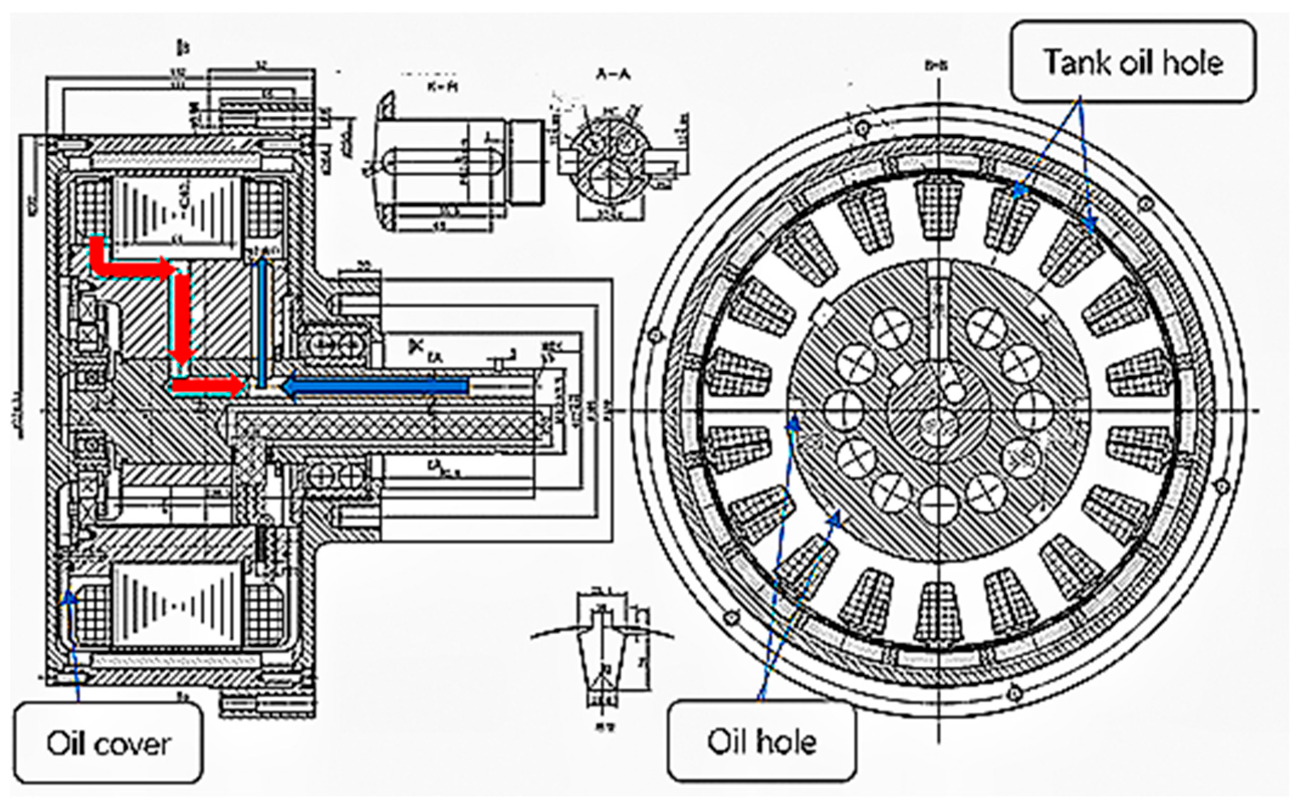
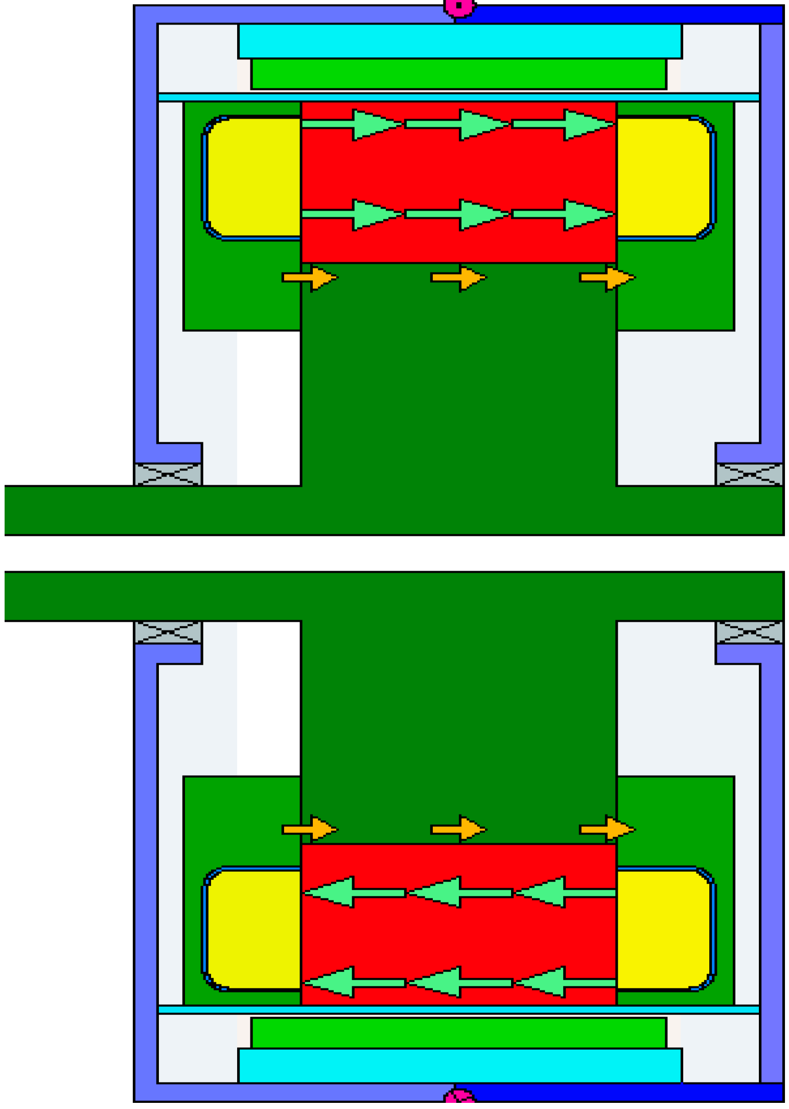
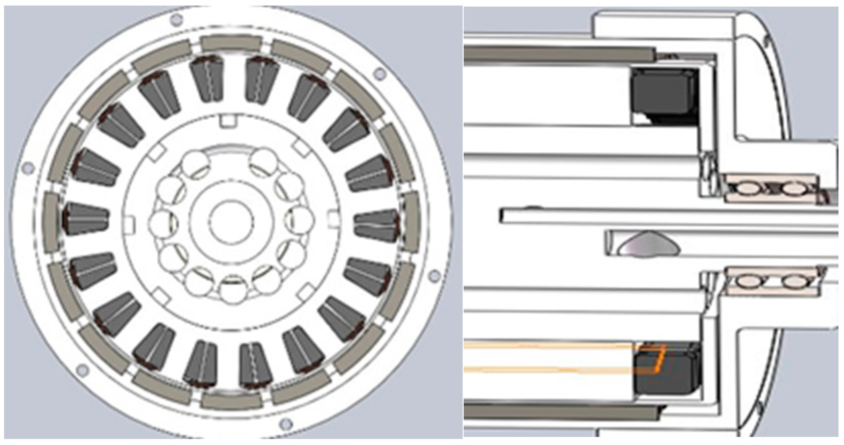
2. Oil Cooling Structure Model Inside the Outer Rotor Hub Motor

In Figure 1, the blue and red arrow indicates the oil inlet and outlet directions. The internal heat sources of the motor are mainly concentrated in the end windings, slot windings, and stator iron cores due to copper losses in the stator windings and iron losses in the stator iron cores of the motor. The heat in the motor is mainly carried away through the lubricating oil in the form of heat conduction and convection heat transfer. Then, the lubricating oil is cooled by water through a heat exchanger. A set of CAD drawings is shown in Figure 1.The motor end windings are parceled by the cover package, and oil immerses the end windings for cooling. Oil is used to cool the stator winding through the groove wedge, as shown by the light green arrow in Figure 2. The yoke of the stator is provided with eight oil passage holes in Figure 1, which can connect the front and rear oil guide hoods. Meanwhile, the stator core is cooled, as shown by the yellow arrow in Figure 2. The motor parameters are shown in Table 1.
The corresponding 3D model was established by a 3D modeling software according to the parameters in the CAD drawings, as shown in Figure 3.

3. Calculation of the Cooling Oil Distribution

Formula (1) can be used to calculate the copper loss of the hub motor within the whole operating range.
P a c = I 2 R d c R a c / R d c 1 + I 2 R d c
In Formula (1), P a c is the winding loss when passing through an AC current, I is the effective value of AC current, R a c is the equivalent AC resistance of the winding, and R d c is the winding resistance when passing through DC.
Formula (2) is improved based on the Bertotti binomial model. Ph is the hysteresis loss, Pe is the eddy current loss, Pexc is the additional loss of stator core:
p h = k = 1 N K h k f ( B k m a x + B k m i n ) p e = K e k = 1 N K e k 2 f 2 ( B k m a x 2 + B k m i n 2 ) p e x c = K e x c 1 T 0 T d B r t d t 2 + d B t t d t 2 2 d t
Br and Bt are radial and tangential flux densities in the core. Kh is the hysteresis loss coefficient, Ke is the eddy current loss coefficient, and Kexc is the additional loss coefficient of the stator core; α is the hysteresis loss calculation parameters, Bkmax is long axis magnetic flux density, and Bkmin is short axis magnetic flux density.
The heat generated during the motor operation is carried away by the fluid, and the required volume flow of the cooling medium is calculated according to the conservation of energy as follows:
q v 1 = p h 1 c a Δ τ a q v 2 = p h 2 c a Δ τ a q v n = p h n c a Δ τ a q v 1 + q v 2 + . . . + q v n = p h c a Δ τ a
Σph: loss to be carried away by the cooling medium; Ca: specific heat capacity of the cooling medium; and Δτa: temperature increase in the cooling medium after passing through the motor.
Due to different losses caused by the motor windings, iron cores, and permanent magnets, the temperature increase in each part also varies. The lubricating oil should be reasonably distributed according to the temperature increase in each part to satisfy the heat dissipation requirements of each part.

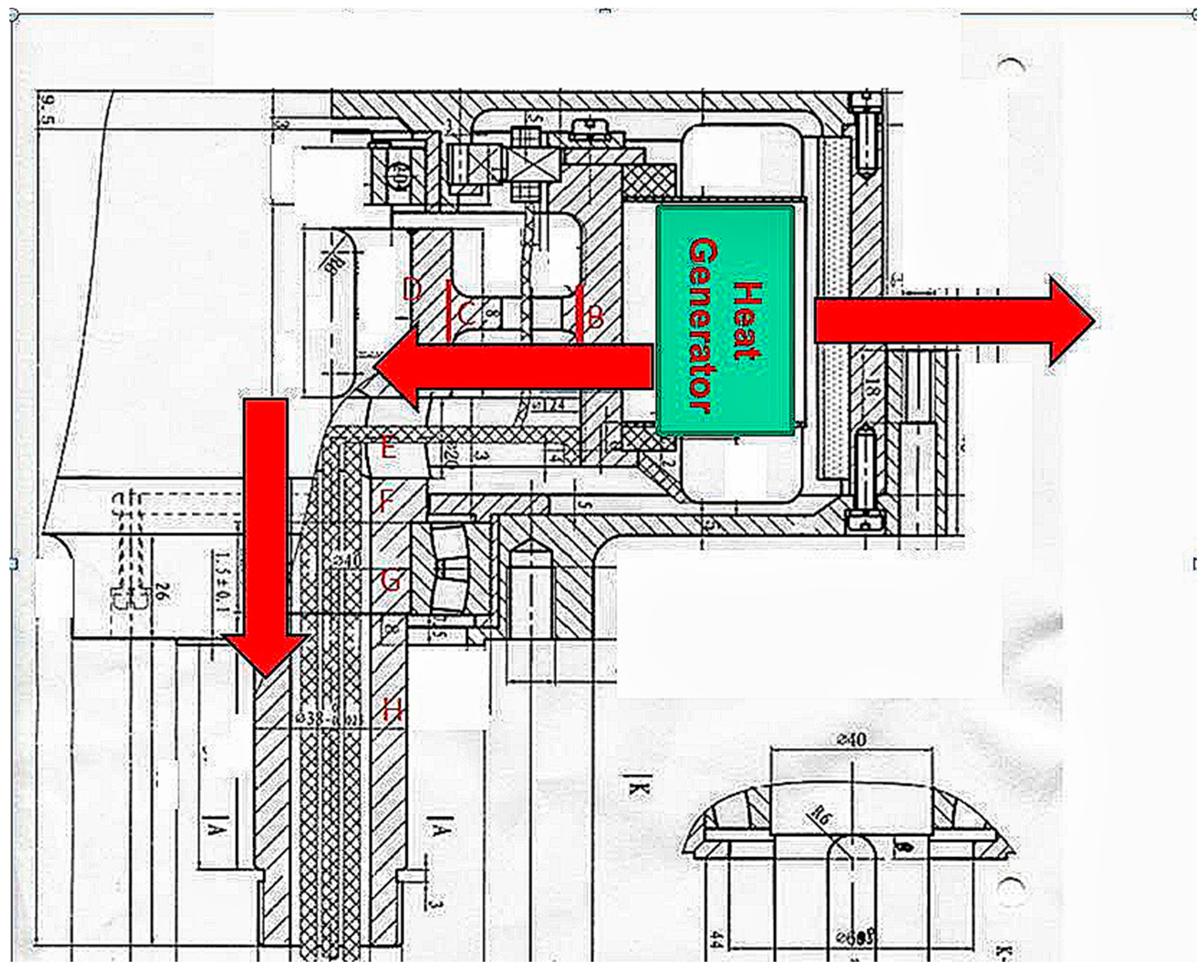
4. Motor Heat Distribution Model

In the running process of the motor, the loss of the motor is mainly generated in the stator core and stator windings of the motor. The thermal path of the motor mainly exists in two directions, transmission through the stator side of the motor, and through the air gap of the motor, which is subsequently transmitted to the air through the permanent magnet and rotor core, as shown in Figure 4. According to the traditional motor design, the thermal resistance in the air gap of the motor is generally believed to be larger than other parts, and the heat is mainly transferred to the air through the motor stator, and stator oil circuit is along the direction of BCDEFGH in Figure 4. However, the hub motor in this project is an outer rotor motor. In addition to the heat transmission through the stator axis, there is a thermal path from the motor air gap to the outer surface of the rotor [22,23,24,25].
Stator side: The stator side of the motor is divided into seven parts according to specific sizes and shapes, which are BCDEFGH. B is the hollow cylinder adjacent to the stator core, C is a hollow disk structure, D is a solid cylinder, and E, F, G, and H are hollow cylinders with different inner and outer radii, as shown in Figure 4.
Rotor side: The calculation of the air gap thermal resistance is included into the rotor side. The main medium in the air gap is air. The stator and rotor have a concentric rotating barrel. The outer wall (rotor side) of the barrel rotates while the inner wall (stator side) of the barrel is stationary. The distribution diagram of the entire thermal circuit of the motor is shown in Figure 5. In Figure 5, the stator side, rotor side, and motor end windings of the motor are labeled. The analysis of Figure 5 shows that on the stator side, the motor hollow shafts C, D, E, F, G, and H are equipped with flow channels, and the thermal resistance of the lubricating oil is 0.3799 k/W. Meanwhile, the maximum thermal resistance on the rotor side of the motor is 0.439314 k/W, which is larger than that of the lubricating oil. Therefore, the heat of the stator of the motor is mainly carried away by the cooling oil, and part of the heat is carried through the air gap of the motor. Then, the magnetic steel, rotor yoke, and motor housing are used as thermal paths to dissipate heat, as shown in Figure 4.
The thermal resistance of the hollow cylinder in the motor is shown as follows:
R j y = ln D j o D j i 2 π L j k F e
R j y : thermal resistance of hollow cylindrical components in the motor. D j 0 : the outer diameter of hollow cylindrical parts inside the motor. D j i : the inner diameter of hollow cylindrical parts inside the motor. k F e : thermal conductivity of the iron core. L j : axial length of hollow cylindrical parts in the motor.
Motor stator tooth thermal resistance:
R t h s t = 0 y d m a x 1 k F e Q s L u x d ( y )
R t h _ s t : Motor stator tooth thermal resistance. k F e : Core heat transfer coefficient. L u : Axial length of stator teeth. Q s : Stator teeth. x d ( y ) : Stator tooth width. y d m a x : Stator tooth depth.
y d m a x = y d 1 + y d 2 + y d 3 + y d 4
The geometric size diagram of the stator tooth is shown in Figure 6.
Since the shaft length is much larger than the radius of the motor shaft, it is generally believed that the main path of heat transfer in the motor shaft is along the direction of the motor shaft rather than along the direction of the motor radius [26].
R t h _ s h = L s h π r s h 2 k s h
R t h _ s h : motor shaft thermal resistance; L s h : length between two bearings of motor shaft; r s h : motor shaft radius; and k s h : thermal conductivity of motor shaft.
The following assumptions are made for stator slots: 1. all conductors in the slots are evenly arranged, and the temperature difference is ignored; 2. copper wire insulation paint is evenly distributed; and 3. winding impregnating paint is completely filled.
Under the above assumptions, all copper wires in the slot can be regarded as an equivalent heat conductor. The equivalent insulation is evenly distributed around the copper strip, as shown in Figure 7.
The calculation formula of insulation thermal conductivity in the slot is as follows:
λ = i = 1 n δ i i = 1 n δ i λ i
δ i : winding insulation paint, slot insulation, and air gap thickness (m); λ i : thermal conductivity of winding insulation paint, slot insulation, and air gap thickness (W/m·K).
The internal thermal resistance of the motor slots includes the insulation thermal resistance, the dip paint, and the air thermal resistance. The equivalent thermal resistance in the motor slot can be expressed as follows [27,28]:
R s l o t = l e q k s l o t A s l o t
l e q = S s l o t S c u l s p
l e q : equivalent slot insulation thickness; k l s o t : the equivalent thermal resistance coefficient in the slots; A s l o t : slot insulation surface area; S s l o t : cross-sectional area of stator slots; S c u : cross-sectional area of the conductor in the slot; and l s p : circumference of stator slot.
Air gap thermal resistance: the convection heat transfer coefficient of the air gap between the stator and rotor can be calculated by Nusselt Number.
h 2 = N u k a i r 2 δ
Nusselt Number is determined by Talyor Number:
N u = 2 T a 41 N u = 0.212 T a 0.63 p r 0.27 41 < T a 100 N u = 0.386 T a 0.5 p r 0.27 100 < T a
The calculation formula of Talyor number is as follows:
T a = R e δ r δ
R e = v a v δ μ
δ : the air gap length; r δ : average air gap radius; v a v : the average velocity of the flow; and μ : dynamic viscosity of the flow.
Convective heat resistance Rc is inversely proportional to convective heat transfer coefficient and contact area:
R c = 1 h A c
For the oil-cooled permanent magnet synchronous motor with an external rotor, there are four groups of convection heat transfer between the windings in the slots and lubricating oil, end winding and lubricating oil, stator core and lubricating oil, and motor stator shaft and lubricating oil.
When the motor is cooled by oil, the heat transfer coefficient of the fluid is calculated as follows:
α = 91.8 v 0.8 39.5 + θ 0.35 d e 0.2
v: velocity of flow (m/s2). θ : the average temperature of the fluid (°C). de: hydraulic diameter of the fluid (m).
There are two parts related to the thermal resistance of the oil cover. One part is the convection thermal resistance R1 between the oil cover and the lubricating oil; the other part is the contact thermal resistance R2 between the oil cover and the stator yoke. The two parts of the thermal resistance calculation formula are shown in the following formula, and the thermal resistance network is shown in Figure 8.
R 1 = 1 α h c A h c
R 2 = 1 π h c L r 1
c 1 = M e c e + 1 2 M f c f
L: stator core length. r 1 : outer diameter of the stator. M e : the quality of end cover. M f : oil shield mass. c e : specific heat capacity of end cap. c f : specific heat capacity of oil shield. h c : core contact coefficient of oil shield [29,30].
Thermal conductivity of each part of the motor material is shown in Table 2. Convective heat transfer coefficient on the cooling surface is shown in Table 3. The thermal resistance of each part of the motor is shown in Table 4.

5. Temperature Field Simulation

At present, the equivalent heat network method and finite element method are commonly used to calculate the temperature field. Although the finite element method has a high calculation accuracy and good boundary adaptability, the solution time is relatively long. The thermal network method is mature in solving technology and can obtain a higher calculation accuracy and shorter solving time under reasonable network partition and parameter settings. Therefore, the thermal network method is used in this section to analyze and calculate the motor temperature field. Motor-CAD simulation software is used to analyze the motor internal temperature distribution in different working conditions. We set the interface between the oil, air gap, and the motor as boundary conditions. The initial oil temperature is 26 °C, the oil flow is 3 m3/h, and the end cap oil transfer coefficient is 185.1 W/m2·K.

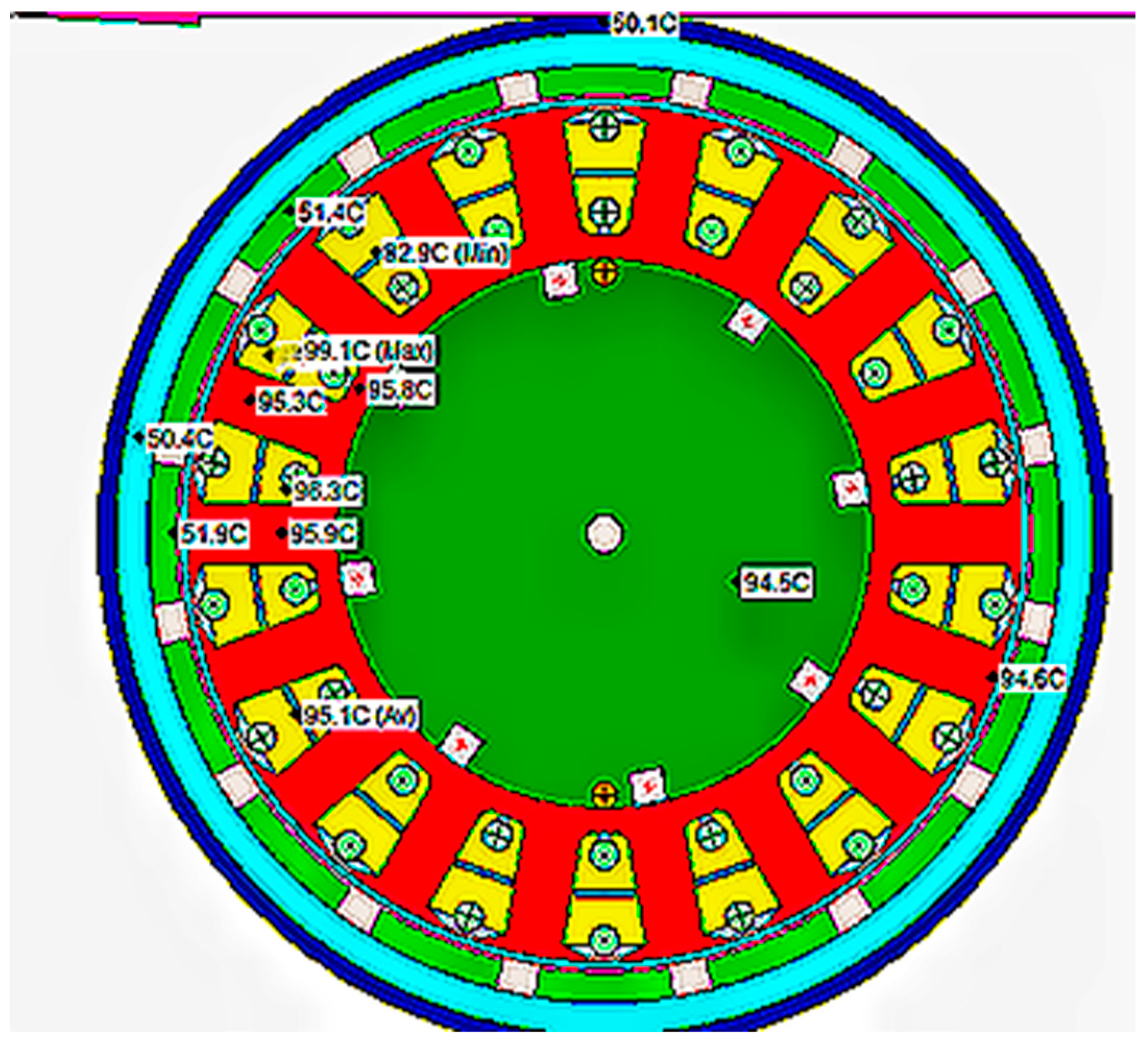
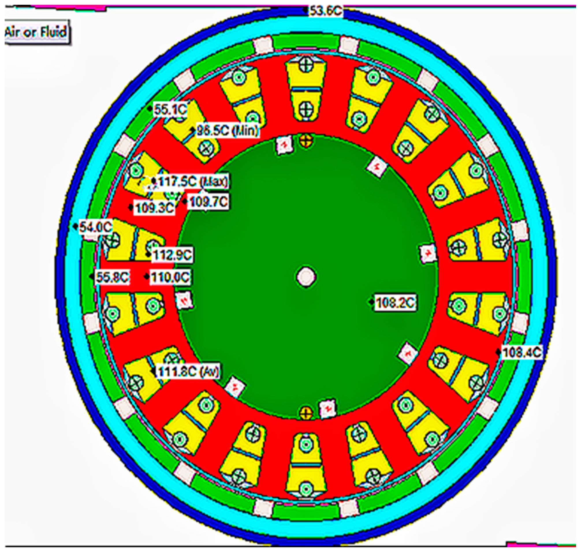
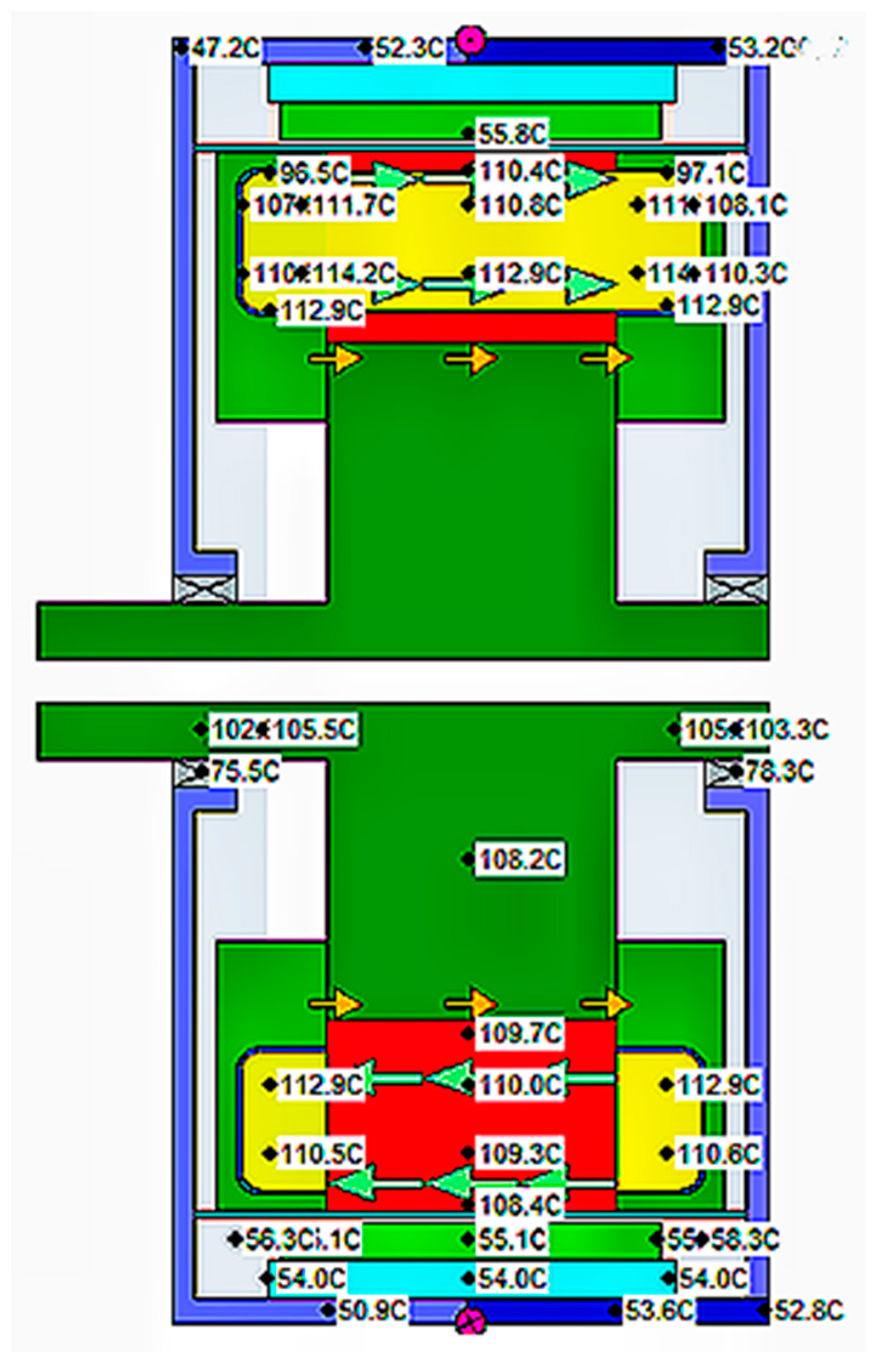
5.1. Simulation Results of the Rated Operating Conditions

The rated working condition of the motor is 10 KW and 636 r/min to obtain the loss of each part of the motor. The corresponding part of the motor thermal model is set with the loss, and the oil cooling condition is simulated by setting the boundary condition of the stator side. According to these parameters in the motor model set that correspond to the material properties and boundary conditions, the oil temperature is 34 °C, and the simulation results in the oil-cooled motor measurement under the rated conditions.
Figure 9 and Figure 10 show the oil cooling motor measurement under the rated conditions of the simulation results. The highest temperature in front of the winding is 97 °C, the average temperature of the stator internal winding is 93 °C, and the highest temperature of the stator iron core is located in the teeth of 96 °C. The stator choke with oil cooling can effectively reduce the stator core temperature.
From Figure 11 the temperature distribution diagram of the outer rotor water-cooled motor, it can be seen that the temperature in the middle and end of the motor winding is relatively high, with the highest temperature of the winding reaching 133 °C and the stator core temperature reaching 125 °C. The main reason is that the cooling medium water is a conductive medium. To ensure the insulation safety of the motor, the cooling water channel can only be arranged near the core, and the cooling area is relatively small. Compared with water cooling, oil cooling has a better cooling effect, with the highest winding temperature reduced from 133 °C to 97 °C, decreasing by 27%, and the stator core temperature was reduced from 125 °C to 94 °C, decreasing by 25%.

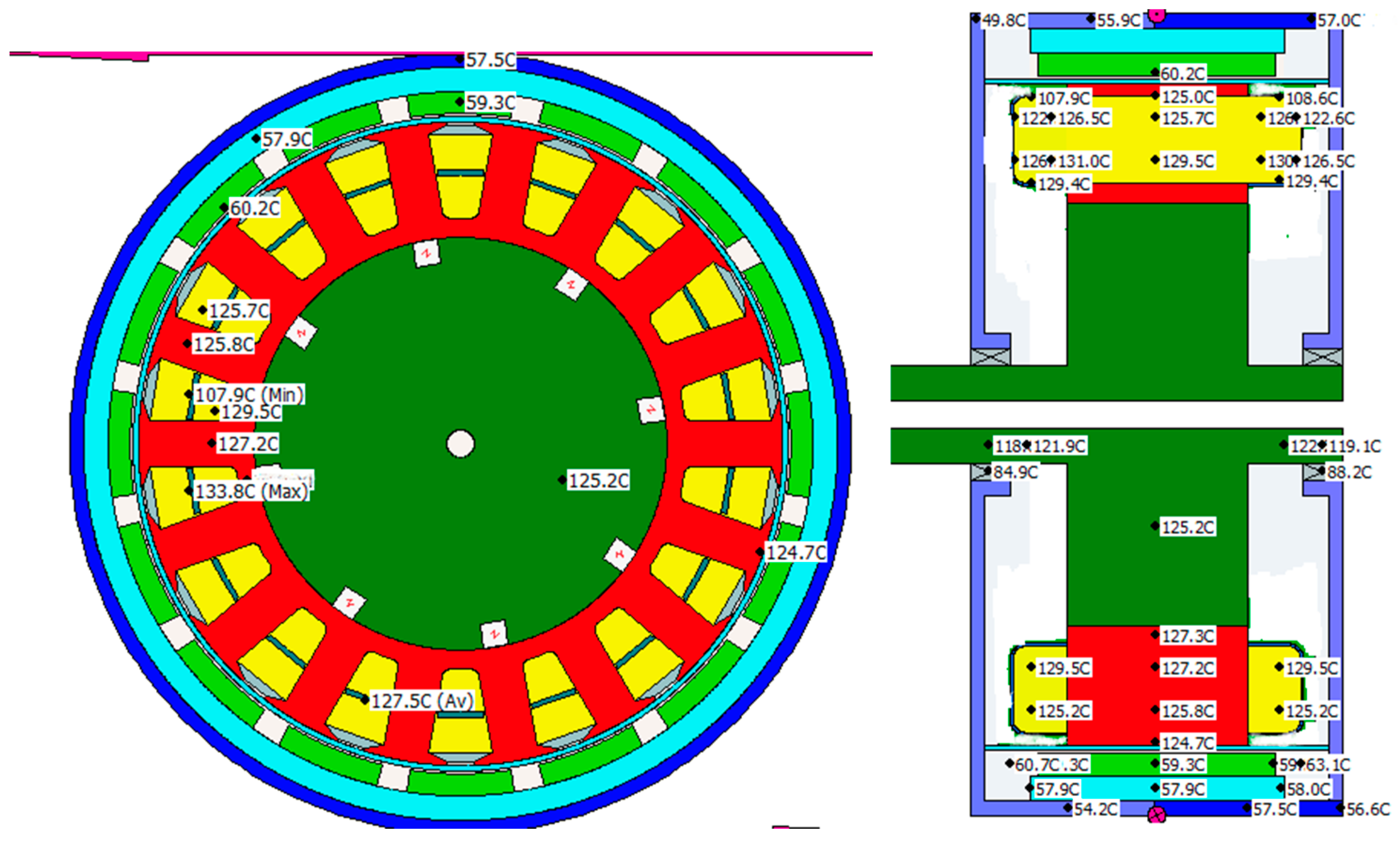
5.2. Simulation Results of Low Speed and High Torque Condition

Figure 12 and Figure 13 show the simulation results for the working condition of the low speed and high torque (189 r/min, 335.9 Nm) of the oil cooling motor. The motor efficiency in this condition is approximately 50%. The highest temperature in front of the winding is 114 °C, the average temperature of the stator internal winding is 111 °C, and the highest temperature stator core is in the teeth of 110 °C.
Through the temperature distribution, we can conclude the following: Compared with water cooling, oil cooling has a better cooling effect, with the highest winding temperature reduced from 133 °C to 97 °C, decreasing by 27%, and the stator core temperature reduced from 125 °C to 94 °C, decreasing by 25%, at the rated operating conditions. The oil cooling method can effectively reduce the temperature of the stator winding and stator core inside the motor and has a better cooling effect compared to the water cooling method. The temperature of the permanent magnet is 96 °C, thereby reducing the possibility of the demagnetization of the permanent magnet and improving the motor’s ability to adapt to high temperature working environments.

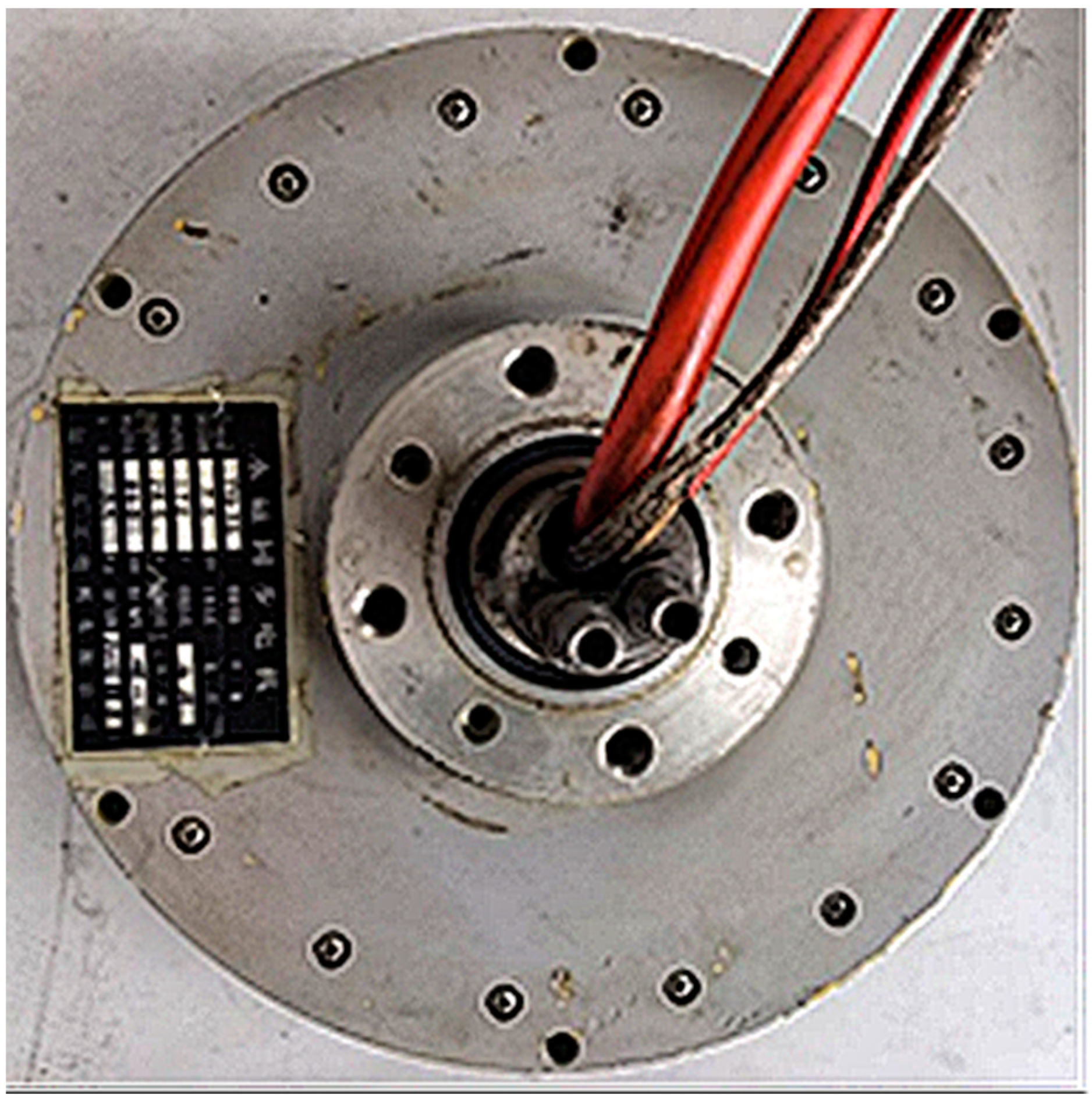
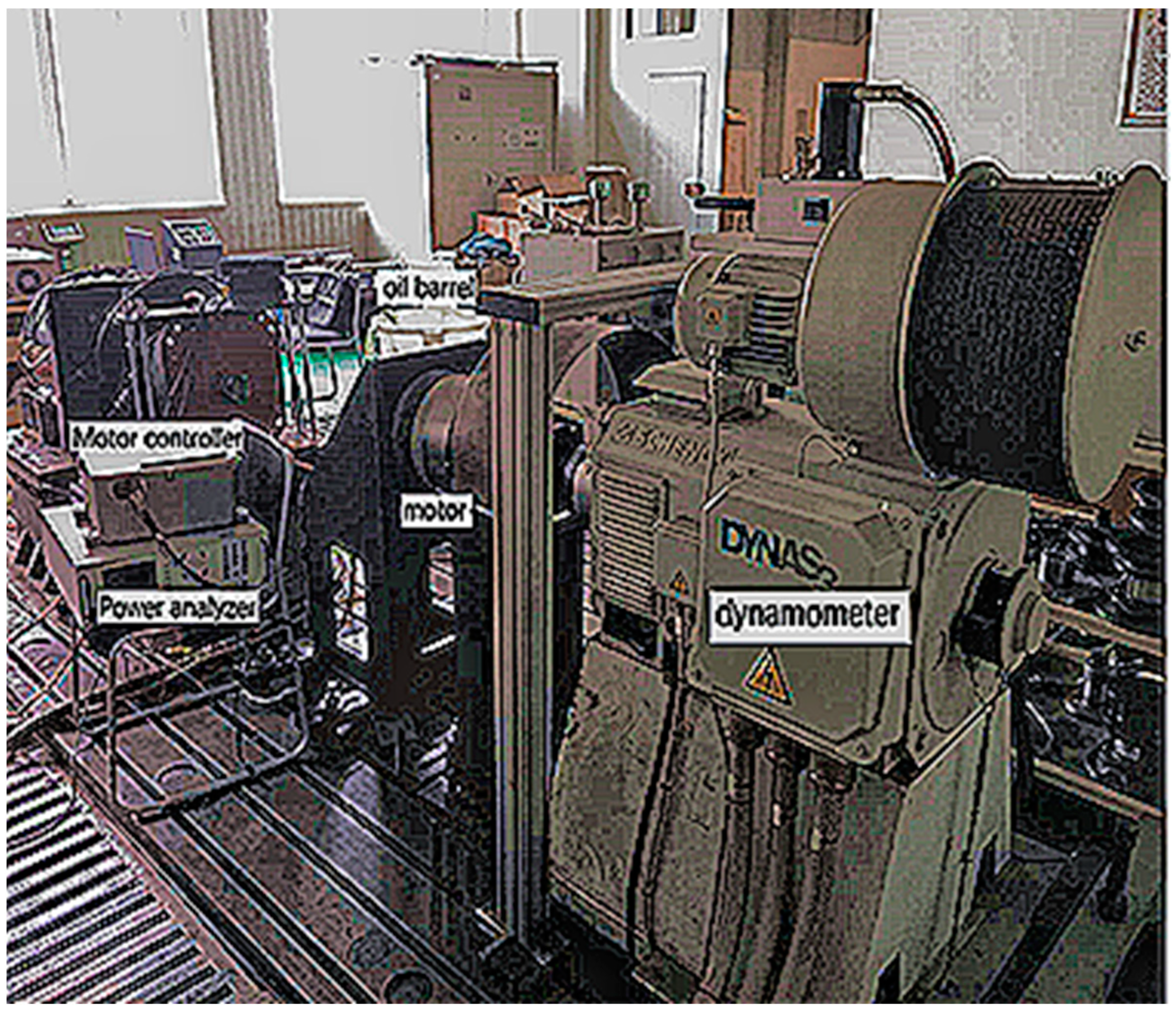
6. Motor Test Analysis

The 32 Great Wall lubricating oil can satisfy the insulation requirement. The viscosity of this lubricating oil is 33.2 mm2/s, its flash point is 230 °C, and pour point is −15 °C. Its thermal conductivity is 0.147 W/m·K. The motor does not reach the flash point temperature during operation, and this oil is not easily evaporated. At present, this oil is commonly used for lubrication in cars. Choosing this oil as a coolant is also to integrate the cooling and lubrication systems of the entire vehicle in the future, reducing the layout of the vehicle chassis pipelines. To maintain the original structural elements of the motor as much as possible, the heat transfer path is particularly best to maintain the same motor internal oil cooling technology. A PT1000 temperature sensor (Beijing Science and Technology Instrument) with a measurement accuracy of 0.1 °C is installed inside the oil outlet pipe to read the temperature at the oil port, and another PT1000 temperature sensor is installed on the oil pump side to measure the temperature at the inlet. The PT1000 temperature sensor embedded inside the motor is connected to the last temperature gauge head to measure the temperature of the motor end winding. The pump flow is 3 m3/h. The initial test environment temperature is 18.7 °C. The outer rotor hub motor operates under rated conditions, the input voltage is 355 V, the input current is 34 A, the motor speed is 800 r/min, the motor torque is 125.5 Nm, and the system efficiency is 87%.
Figure 14 shows the motor prototype. Figure 15 shows the test bench of the motor. The temperature sensor at the inlet is located inside the oil drum, the outlet temperature sensor is adhered to the outlet wall, and two temperature sensors are embedded in the motor.
Figure 16 shows the one-hour temperature increase data of the motor winding under the rated working conditions as measured in the experiment.
Figure 17 shows the one-hour temperature rise curve of the outer rotor hub motor under two cooling methods: oil cooling and water cooling. Comparing the winding temperature rise curves obtained from the experiment, it was found that the temperature rise of the water-cooled motor was significantly higher than that of the oil-cooled motor after one hour. The oil-cooled motor reached thermal equilibrium in about 20 min when running at a rated power of 10 kw, that is, the heat generated inside the motor was equal to the heat carried away by the cooling system. The winding temperature rise was 41 °C, and the temperature rise of the water-cooled motor was 65.3 °C. The temperature rise of the oil-cooled motor was significantly better than that of the water-cooled motor; the temperature of the water-cooled motor continues to rise within 1 h, indicating that the water-cooled system is not taking enough heat away, and the temperature of the motor will continue to rise as it continues to operate. So, the oil cooling method has a better cooling effect than the water cooling method.
Table 5 shows the test results of the outer rotor hub motor under low speed and high torque conditions. Under this condition, the motor efficiency is 43.7%, and the winding temperature rises from 56.3 °C to 118 °C within 30 s. The previous simulation showed that the maximum temperature of the motor winding under low speed and high torque conditions was 114 °C in Figure 11 and Figure 12. The small difference between the experimental and simulation results validates the accuracy of the simulation, indicating that the increase in internal losses of the motor leads to a rapid increase in winding temperature. Under this condition, the motor cannot operate for too long.

7. Conclusions

At present, several cooling methods for wheel hub motors mainly focus on cooling the end windings or stator iron cores with a single heat source, and the cooling effect is still insufficient. Therefore, a form of simultaneous oil cooling with multiple heat sources inside the motor was proposed, and an oil cooling structure was designed with end oil guide covers wrapped around the end windings for oil immersion cooling, stator choke openings for cooling the stator core, and reserved oil passages in the slots for cooling the windings inside the slots.
The heat dissipation methods in the literature mostly calculate the total cooling medium required by the motor based on the total loss of the motor, which can lead to an uneven distribution of the local heat source cooling medium and low cooling efficiency. The temperature rise of each part of the wheel hub motor is also different due to the different losses generated by the motor winding, iron core, and permanent magnet. Therefore, lubricating oil should be reasonably distributed according to the temperature rise of each part to meet the heat dissipation requirements of each part. A calculation method for the distribution of cooling medium inside the motor is proposed.
The temperature field simulation of the outer rotor permanent magnet synchronous wheel hub motor under low speed, high torque, and rated power conditions was carried out using the centralized parameter thermal network method, and the temperature distribution inside the motor was obtained. Through the temperature distribution, we can conclude the following: compared with water cooling, oil cooling has a better cooling effect, with the highest winding temperature reduced from 133 °C to 97 °C, decreasing by 27%, and the stator core temperature reduced from 125 °C to 94 °C, decreasing by 25%, at the rated operating conditions.
By conducting a motor temperature rise test, experimental data were obtained and compared with simulation results and experimental results under water cooling conditions. Through comparison, the following was found: 1. When the outer rotor oil-cooled wheel hub motor runs for 20 min under rated conditions, the temperature rise gradually stabilizes and reaches thermal equilibrium. The winding temperature eventually reaches 88.7 °C, while the simulation results under rated conditions show that the highest temperature of the winding is 97 °C. The temperature rise curve of the oil-cooled winding and the simulated winding temperature rise curve show good consistency. 2. The temperature rise of the winding in the water-cooled method is significantly higher than that of the oil-cooled motor within 1 h, and the temperature of the winding continues to rise within 1 h. The cooling effect of the oil cooling method was better than the water cooling method, which verifies the rationality of the oil cooling structure. 3. When the outer rotor oil-cooled wheel hub motor runs for 30 s under low speed and high torque conditions, the temperature rises from 56.3 °C to 118 °C, indicating that the increase in the internal losses of the motor leads to a rapid increase in the temperature rise of the motor winding. However, the previous simulation showed that the highest temperature of the motor winding under low speed and high torque conditions was 114 °C, which is not significantly different from the experimental results, verifying the accuracy of the simulation. The motor cannot work for a long time under the same operating conditions.

Author Contributions

Methodology, F.G.; Investigation, F.G.; Resources, C.Z. All authors have read and agreed to the published version of the manuscript.

Funding

This research was funded by [Guangdong Mechanical and electrical polytechnic] grant number [Gccrcxm-202008].

Data Availability Statement

The original contributions presented in the study are included in the article, further inquiries can be directed to the corresponding author.

Conflicts of Interest

The authors declare no conflict of interest.

References

  1. Staton, D.A.; Cavagnino, A. Convection Heat Transfer and Flow Calculations Suitable for Electric Machines Thermal Models. IEEE Trans. Ind. Electron. 2008, 55, 3509–3516. [Google Scholar] [CrossRef]
  2. Márquez-Fernández, F.; Reinap, A.; Huang, Z.; Alaküla, M. Design, optimization and construction of an electric motor for an Electric Rear Wheel Drive Unit application for a Hybrid Passenger Car. In Proceedings of the XIX International Conference on Electrical Machines-ICEM 2010, Rome, Italy, 6–8 September 2010. [Google Scholar]
  3. Zhou, Z.; Yang, W.; Li, Z. Temperature Field and Thermal Stress of External Rotor In-Wheel Motor. J. Chongqing Jiaotong Univ. (Nat. Sci.) 2022, 41, 142–150. [Google Scholar]
  4. Chai, X. Temperature Rise and Heat Dissipation Analysis of In-wheel Motor Angle Module System under the Action of Multi-physics Coupling. Automob. Appl. Technol. 2023, 48, 124–134. [Google Scholar]
  5. Liu, Z.; Yan, Y. Research on axial U-shaped water channel cooling structure of hub motor. J. Shanghai Univ. Eng. Sci. 2023, 37, 240–246. [Google Scholar]
  6. Li, Y.; Fan, T.; Wen, X.; Li, Y. Numerical research on hydraulic and thermal performance of the motor water jackets based on the orthogonal experiment. Int. Conf. Electr. Mach. Syst. 2013, 2013, 860–863. [Google Scholar]
  7. Jiao, B.F.; Li, D.S.; Du, X. Performance analysis and experimentation of a liquid-cooled eddy current retarder with a dual salient poles design. IEEE Trans. Energy Convers. 2014, 29, 84–90. [Google Scholar] [CrossRef]
  8. Lindh, P.M. Direct Liquid Cooling in Low-Power Electrical Machines: Proof-of-Concept. IEEE Trans. Energy Convers. 2016, 31, 1257–1266. [Google Scholar] [CrossRef]
  9. Liu, M.; Li, Y.; Ding, H.; Sarlioglu, B. Thermal management and cooling of windings in electrical machines for electric vehicle and traction application. In Proceedings of the 2017 IEEE Transportation Electrification Conference and Expo (ITEC), Chicago, IL, USA, 22–24 June 2017; pp. 668–673. [Google Scholar]
  10. Wu, W.; Hu, C.; Hu, J.; Yuan, S. Cooling for rolling Bearings: Flow visualization and temperature distribution. Appl. Therm. Eng. 2016, 105, 217–224. [Google Scholar] [CrossRef]
  11. Liu, C.Y.; Jiang, K.J.; Zhang, Y. Study on temperature rise performance of eddy current retarder in automobile. In Proceedings of the 2010 International Conference on Future Information Technology and Management Engineering (FITME), Changzhou, China, 9–10 October 2010; pp. 550–553. [Google Scholar]
  12. Camilleri, R. Predicting the Temperature and Flow Distribution in a Direct Oil-Cooled Electrical Machine With Segmented Stator. IEEE Trans. Ind. Electron. 2016, 63, 82–87. [Google Scholar] [CrossRef]
  13. Jungreuthmayer, C.; Bauml, T.; Winter, O.; Ganchev, M.; Kapeller, H.; Haumer, A.; Kral, C. A detailed heat and fluid flow analysis of an internal permanent magnet synchronous machine by means of computational fluid dynamics. IEEE Trans. Ind. Electron. 2012, 59, 4568–4578. [Google Scholar] [CrossRef]
  14. Wang, R.J.; Heyns, G.C. Thermal analysis of a water-cooled interior permanent magnet traction machine. In Proceedings of the 2013 IEEE International Conference on Industrial Technology (ICIT), Cape Town, South Africa, 25–28 February 2013; pp. 416–421. [Google Scholar]
  15. Rashid, M.I.M.; Daniyal, H.; Mohamed, D. Comparison performance of split plug-in hybrid electric vehicle and hybrid electric vehicle using ADVISOR. In Proceedings of the 2nd International Conference on Automotive Innovation and Green Vehicle (AIGEV 2016), Cyberjaya, Malaysia, 2–3 August 2016. [Google Scholar]
  16. Qu, H.; Li, J.; Wang, Y.; Li, Z. Semi-Closed Type Oil Cooling System for Motor for Compressor. CN104467288, 31 December 2014. [Google Scholar]
  17. Wang, K.; Zhu, Z.Q.; Ombach, G. Synthesis of high performance fractional-slot permanent-magnet machines with coil-pitch of two slotpitches. IEEE Trans. Energy Convers. 2014, 29, 758–770. [Google Scholar] [CrossRef]
  18. Ping, Z.; Liu, R.; Thelin, P.; Nordlund, E.; Sadarangani, C. Research on the cooling system of a 4QT prototype machine used for HEV. IEEE Trans. Energy Convers. 2008, 23, 61–67. [Google Scholar]
  19. Polikarpova, M. Liquid Cooling Solutions for Rotating Permanent Magnet Synchronous Machines. Ph.D. Thesis, Lappeenranta University Technology, Lappeenranta, Finland, 2014. [Google Scholar]
  20. Li, Q.; Fan, T.; Wen, X.; Ning, P. An Analytical Approach to Magnet Eddy-Current Losses for Interior Permanent-Magnet Synchronous Machines During Flux Weakening. IEEE Trans. Magn. 2015, 51, 8107109. [Google Scholar]
  21. Caricchi, F.; Crescimbini, F.; Di Napoli, A. Prototype of innovative wheel direct drive with water-cooled axial-flux PM motor for electric vehicle applications. In Proceedings of the IEEE Applied Power Electronics Conference, San Jose, CA, USA, 3–7 March 1996; pp. 764–770. [Google Scholar]
  22. Ulbrich, S.; Kopte, J.; Proske, J. Cooling Fin Optimization on a TEFC Electrical Machine Housing Using a 2-D Conjugate Heat Transfer Model. IEEE Trans. Ind. Electron. 2018, 65, 1711–1718. [Google Scholar] [CrossRef]
  23. Ishak, D.; Zhu, Z.Q.; Howe, D. Eddy-current loss in the rotor magnets of permanent-magnet brushless machines having a fractional number of slots per pole. Magnetics. IEEE Trans. Magn. 2005, 41, 2462–2469. [Google Scholar] [CrossRef]
  24. JMAG Version 10 -User’s Manual Solver; JSOL Corporation: Tokyo, Japan, 2010.
  25. Eason, G.; Noble, B.; Sneddon, I.N. On certain integrals of Lipschitz-Hankel type involving products of Bessel functions. Phil. Trans. Roy. Soc. 1955, A247, 529–551. [Google Scholar]
  26. Liu, R.; Zheng, P.; Xie, D.; Wang, L. Research on the High Power Density Electromagnetic Propeller. IEEE Trans. Magn. 2007, 43, 355–358. [Google Scholar] [CrossRef]
  27. Janna, W.S. Engineering Heat Transfer; Van Nostrand: New York, NY, USA, 1988. [Google Scholar]
  28. Boglietti, A.; Cavagnino, A.; Lazzari, M. A simplified thermal model for variable-speed self-cooled industrial induction motor. IEEE Trans. Ind. Appl. 2003, 39, 945–952. [Google Scholar] [CrossRef]
  29. Staton, D.; Boglietti, A.; Cavagnino, A. Solving the More Difficult Aspects of Electric Motor Thermal Analysis in Small and Medium Size Industrial Induction Motors. IEEE Trans. Energy Convers. 2005, 20, 620–628. [Google Scholar] [CrossRef]
  30. Boglietti, A.; Cavagnino, A. Analysis of the Endwinding Cooling Effects in TEFC InductionMotors. In Proceedings of the IEEE Conference on Industry Applications Conference, Tampa, FL, USA, 8–12 October 2006; pp. 797–804. [Google Scholar]
Figure 1. CAD drawing of the oil-cooled hub motor.
Energies 17 06312 g001
Figure 2. Oil flow diagram of the oil-cooled hub motor.
Energies 17 06312 g002
Figure 3. 3D model drawing of hub oil-cooled motor.
Energies 17 06312 g003
Figure 4. Motor heat generation and transfer path diagram.
Energies 17 06312 g004
Figure 5. Overall thermal circuit diagram of the motor.
Energies 17 06312 g005
Figure 6. Schematic diagram of geometric dimensions of motor teeth.
Energies 17 06312 g006
Figure 7. Equivalent diagram of stator slot winding.
Energies 17 06312 g007
Figure 8. Oil shield thermal resistance network.
Energies 17 06312 g008
Figure 9. Cross-section temperature profile of the oil-cooled motor.
Energies 17 06312 g009
Figure 10. Temperature distribution diagram of the axial section of the oil-cooled motor.
Energies 17 06312 g010
Figure 11. Temperature distribution diagram of the water-cooled motor.
Energies 17 06312 g011
Figure 12. Temperature distribution diagram of the axial section of the oil-cooled motor.
Energies 17 06312 g012
Figure 13. Temperature distribution diagram of the axial section of the oil-cooled motor.
Energies 17 06312 g013
Figure 14. Motor prototype.
Energies 17 06312 g014
Figure 15. Test diagram of the oil-cooled motor bench.
Energies 17 06312 g015
Figure 16. One-hour temperature increase curve of the oil-cooled motor.
Energies 17 06312 g016
Figure 17. One-hour temperature increase curve of the oil-cooled motor and water-cooled motor.
Energies 17 06312 g017
Table 1. Oil-cooled hub motor parameters.
Oil-Cooled Hub Motor ParametersParameters
Highest speed (r/min)1400
Rated power (kw)10
Peak power (30 s)20
Rated torque (Nm)150
Peak torque (30 s)335
Motor quality (kg)35
Table 2. Material and thermal conductivity of each part of the motor.
Motor StructureMaterialThermal Conductivity (W/m·K)Specific Heat Capacity (J/kg·°C)
stator coreDW-46540426
conductorcopper386383
insulation in slotsinsulation paint, slot insulation, air gap0.31340
permanent magnetNdFeB9420
air gapair0.028992
cooling oillubricating oil0.1471796
Table 3. Coefficient of convection heat transfer on cooling surface of motor.
Cooling PositionConvective Heat Transfer Coefficient (W/m2·K)
Oil in stator shaft and iron core23284.1
Oil in slot wedge92401.1
End cap oil185.1
Air gap0.0262
Table 4. Thermal resistance of each part of the motor.
Motor PartsThermal Resistance (k/W)
slot insulation0.012
air gap0.439314
end winding0.52854
stator tooth0.03217
stator reactance0.0205
stator B0.0054
stator C0.176
stator D0.176
stator E + F0.2349
stator G0.305
stator H1.258
permanent magnet0.0126
rotor reactance0.002703
right side shell0.000509
left side shell0.0003685
shell-convection resistance0.27087
copper wire from stator16.375
oil-convection resistance stator core0.37993
oil-convection resistance groove wedge0.4399
oil-convection resistance end cap0.2196
core and oil shield contacts thermal resistance0.562
Table 5. Test data of low speed and high torque operating conditions for external rotor oil-cooled wheel hub motor.
Time
(s)
Torque
(Nm)
Motor Speed
(r/min)
Initial Winding
Temperature (°C)
Terminal Winding
Temperature (°C)
Input DC Voltage (V)Input DC Current (A)System Efficiency
30335.918956.311835546.340%
Disclaimer/Publisher’s Note: The statements, opinions and data contained in all publications are solely those of the individual author(s) and contributor(s) and not of MDPI and/or the editor(s). MDPI and/or the editor(s) disclaim responsibility for any injury to people or property resulting from any ideas, methods, instructions or products referred to in the content.

