Abstract
Post-industrial sites are a part of many cities. The impacts of industrial activities are not only evident in the area where the activity took place, but also affect the buildings within these areas. Buildings that served the industry in the past were built mainly by mass construction methods. From today’s point of view, these buildings are unsatisfactory in terms of typology, operation, and energy. In particular, energy rehabilitation is a way to restore industrial buildings and bring them to a full-fledged state. This issue is documented in a case study of a city affected by underground mining activity and on a selected skeleton construction. Given that industrial buildings have heavy or mass structures where some elements like beams and columns are damaged, it is crucial to consider not only energy solutions, but also the structural and architectural aspects of these buildings. In terms of thermal engineering and energy, including the renovation of structures, a software-supported evaluation of three material variants for the envelope walls of the skeleton construction from the 1970s was conducted. This study evaluates the thermal performance of conventional, proposed, and traditional wall designs by analysing their U-values, thermal resistance, and structural advantages. The results reveal that the conventional wall, featuring a 150 mm EPS 70 NEO insulation layer, achieves the lowest U-value, outperforming the proposed wall by a factor of 1.2 in thermal resistance. Both designs significantly reduce U-values compared to traditional walls, by factors of 6.55 and 5.40, respectively. Despite a 23% reduction in thickness relative to the conventional wall (and 44% compared to traditional walls), the proposed wall demonstrates robust thermal performance. Further benefits include reduced structural dead load, with the conventional and proposed walls being 3.70 times lighter per square meter than traditional walls. This reduction can decrease foundation, column, and beam dimensions, optimizing building design. Thermal bridging analysis highlights superior corner insulation in conventional walls due to higher surface temperatures, while the proposed wall maintains effective insulation with surface temperatures close to indoor conditions. Overall, the findings underscore the importance of advanced materials in achieving efficient thermal performance while balancing architectural and structural demands. The results achieved from the experimental work show that industrial buildings can be effectively energy-renovated in a way that complies with legislative documents, successfully extends the physical life of the frame structures, and contributes to carbon neutrality.
1. Introduction
The post-industrial area is the legacy of industrial sites that are found in many places around the world. As a result of the restructuring measures of industrial locations, which began to take place from around the second half of the last century practically all over the world, the question arose of how to proceed with the industrial heritage and how to solve the post-industrial area [1,2,3,4]. A territory that has been damaged by industrial activity is characterised by a number of specific attributes that need to be addressed. Many authors have drawn attention to this fact [5]. The territory also includes a number of buildings that have lost their original purpose and are looking for a new use. It is no different in Europe, namely in the countries of Eastern Europe [6,7,8,9,10].
When determining the solution concept for how to proceed with post-industrial territory and how to solve abandoned industrial sites, it is necessary to take an integrated approach that focuses on the environmental, social, cultural, technical, and economic areas [11]. The integration of these areas leads to the principles of sustainability. Careful attention needs to be paid to the energy aspect of buildings in post-industrial locations, which has become increasingly important in recent decades. This is justified because the European Union (EU), including the countries of Eastern Europe, has pledged to pursue a course towards climate neutrality [12,13,14,15]. The EU has ambitious goals in this regard and, within the framework of the “Green Deal” [16] and the European “Climate Act” [17], has set itself the goal of reducing greenhouse gas (GHG) emissions by at least 55% by 2030 compared to 1990 levels and becoming climate-neutral by 2050. The “Climate Act” includes, among other things, building renovations and green investments. A strategic follow-up document related to buildings is the EPBD (Energy Performance Buildings Directive [18]), which supports significant reductions in energy consumption in buildings across the EU. The EPBD series directive represents a solid framework for the decarbonisation of buildings for the community of EU countries, introduces national renovation schemes for EU member states, and simultaneously sets goals for the introduction of solar energy. The framework of this directive places emphasis on cost-effectiveness in the reconstruction and modernisation of buildings. This results in requirements for the modernisation and reconstruction of all buildings, including buildings that are located in post-industrial locations and are looking for a new use.
Post-industrial locations are home to buildings that, in many cases, were built using prefabricated skeleton construction systems. Prefabricated skeletons found their application in industrial construction, especially in the second half of the last century [19]. For example, in the Czech Republic (CZ), the types of prefabricated skeletons used for the construction of not only industrial buildings, but also for the construction of civil facilities for the city, spread very quickly.
These were, for example, type Assembled Skeletons of Civic Amenities with assembled perimeter walls (known under the abbreviation MSOB in CZ; in the English version, under the abbreviation ASCA) [20]. Other skeleton systems that were implemented in the Czech Republic included Structural Element Skeletons; skeletons of industrial construction; Constructive Prague skeletons; Integro skeletons; and type series of assembled skeletons marked S1.1., S1.2., and S1.3. from State Technical Institute [21,22].
After the decline in industrial activity, the skeleton structures remain abandoned, dilapidated, and have lost their original purpose. If we are to regenerate post-industrial localities aiming towards sustainability, industrial buildings in the framework construction system and buildings (also in the framework construction system) that form an integral typological part of post-industrial areas are an essential part of those regenerations. Before starting renovation work, with regard to the new energy concept, it is advisable to focus on mapping the current state of the buildings as a whole, while at the same time developing a strategy for achieving energy savings [23]. We want to document the aforementioned strategy with the example of a building built in the 1970s and 1980s of the last century on the territory of the Ostrava-Karvina region in CZ as a prefabricated skeleton structure of the ASCA type series. We characterise the territory of the Ostrava-Karvina region as an area affected by increased industrial activity, i.e., metallurgy, energy, mining of minerals, chemical industry, and coke plants. With regard to the breadth of the issue, we focused on the external wall of the selected skeleton structure. New designs and new conceptual solutions for perimeter walls linked to energy savings and climate neutrality strategy include wall insulation, air tightness membrane/seals, automated blinds, glazing, cooling, and covering. These measures are in line with the concept of Efficient Building Europe [24].
Walls play a crucial role in reducing a buildings’ energy consumption and thereby cutting energy costs. Choosing the right wall materials can significantly decrease energy usage. Moreover, the demand for and consumption of energy lead to a significant environmental problem. In addition, building energy consumption accounts for 28% of energy savings related to CO2 emissions. The energy renovation of buildings’ perimeter walls in post-industrial locations, for which society is seeking a new and functional purpose, is very important and has its own justification. Energy renovation not only improves the energy portfolio of these buildings, but, with the right design, also contributes to carbon neutrality.
Despite the wealth of literature dealing with the issue of external walls, it is a fact that with the current EU strategy, aiming at energy efficiency of buildings and climate neutrality by 2050, knowledge is generally limited in the area of effective material solutions for the wall cladding of prefabricated post-frame industrial locations that would contribute to the fulfilment of the ambitious goal of climate neutrality in solution. It should be emphasized that skeletons from the second half of the last century, especially in Eastern European countries, are characteristic of post-industrial localities and have great potential for renovations.
Industrial estate buildings are typologically divided into single-purpose production buildings and multi-purpose production buildings [25]. Single-purpose buildings have limited layout and operational variability for new functional use because they were purposefully focused on, for example, one production process. In contrast, multi-purpose skeletons are highly variable. These skeletons allow for very good solutions for new spatial arrangements and have a sufficiently large potential for other various uses; they are spatially flexible. A typical example of a multi-purpose skeleton is the ASCA type series mentioned above. In the second half of the 20th century, this system was used in the Ostrava-Karvina region (CZ) for the construction of light industry buildings and service facilities and was widely used in the construction of civic buildings.
In many cases, the revitalization of industrial estate buildings, part of the external envelope, is achieved by complete dismantling the original external envelope with the subsequent implementation of a new external envelope. The original envelopes of the skeletons are usually significantly degraded, without maintenance, and completely unsatisfactory from a thermal technical point of view; therefore, dismantling the external envelope is a logical path of reconstruction. Variant solutions for the new external envelope are usually available as part of the reconstruction. The aim is to select a solution that can significantly change the balance of heat losses and gains, which leads to a reduction in the need for heat [26,27]. With regard to the above-mentioned legislative sources and strategic measures by the EU, when reconstructing energy-inefficient buildings of post-industrial estates, it is necessary not only to take into account better energy efficiency, but also to support such reconstruction measures that lead to decarbonised buildings [28]. Such reconstructions can then be considered successful, and also make sense from an economic point of view. In terms of replacing the external envelopes of skeleton buildings of post-industrial estates, a number of material solutions are currently available. It is therefore necessary to choose a material solution for the reconstruction of the building’s external envelope that minimizes environmental impacts, is energy efficient throughout its life cycle, is durable, and is aesthetic.
There is a research gap in post-industrial settlement frame buildings and their renovations that would demonstrate that these frame buildings can be successfully renovated and their lifespan can be extended, thus allowing them to contribute to the EU’s ambitious climate neutrality goal.
It can be assumed that, as a result of dynamically developing society and new technologies, there will be requirements for the flexibility of structures and flexibility of use of buildings in post-industrial settlements, including their reconstruction. Successfully reconstructed skeleton buildings in post-industrial settlements will be an interesting investment for many investors. The strategy, which is the path of reconstruction, will avoid the demanding demolition of skeletons, and in many cases the loss of their physical viability. As stated in [29,30], premature demolition and failure to use the physical lifespan of facilities gradually increase the “…debt of society…” to the environment. The supporting skeleton systems of facilities reach a standard lifespan of 50 years [31]. If a successful reconstruction is carried out, the lifespan can be extended by another 30–40 years. This is very similar to the case of panel residential construction (Appendix A). It is also necessary to mention that the distinctive features of skeletons in comparison with masonry structures are significantly smaller cross-sectional dimensions of load-bearing elements, as well as integrity and connectivity of mechanical and physical properties of the structure such as: greater shape, dimension, and spatial adaptability to functional and static requirements. These advantages of skeletons lead to their ability to adapt over time.
The aim of the work is to present the possible variability of material solutions for the perimeter wall by decreasing the mechanical load on the structures during the renovation of prefabricated skeletons, which supports energy savings and, at the same time, contributes to climate neutrality. At the same time, we seek to fill the gap in research on skeleton buildings in post-industrial settlements and support the prediction of their lifespan.
2. Materials and Methods
Using the example of a case study of a post-industrial locality in the Ostrava-Karvina region (Figure 1a,b), we analysed a new conceptual design of a building perimeter wall for a prefabricated structural skeleton system (case study findings are supported by the project “Energy efficient solutions and strategies for different types of buildings”).
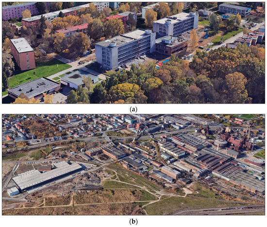
Figure 1.
Post-industrial locality and area for monitoring: (a) monitored building in a skeleton construction system, part of case study; (b) broader situation in the neighbourhood [32].
This is a ASCA type series skeleton, which is characteristic of the territory of the Ostrava-Karvina region (CZ). This skeleton was developed in the years 1973–1983 by the Research and Development Institute of Civil Engineering in Ostrava (CZ). These skeletons were very widespread, especially in the locality of the Ostrava-Karvina region, characterised today as a post-industrial locality, where extensive deep coal mining took place. A characteristic feature of ASCA type series skeletons is that they were used for the construction of both civic buildings of the city and industrial buildings. In the second half of the last century, it was a very excellent, economically advantageous construction strategy which not only prioritised the speed of construction (advantage in applying the seriality of structural elements), but also made it possible to build industrial buildings (warehouses, production halls, etc.) and administrative buildings, buildings of social facilities, etc. These buildings suitably complemented the industrial location. An axonometric view of the ASCA skeleton structure is shown in Figure 2. Currently, these skeleton buildings are either completely abandoned or in a state of disrepair. Figure 3 shows the significant degradation of the skeleton, and it is also apparent that the original perimeter wall based on the material of light concrete is completely inadequate for the current conditions and energy strategies. Energy-efficient solutions and strategies for different types of buildings are needed.
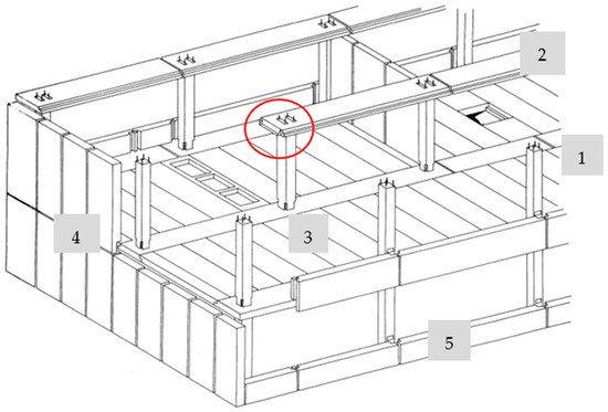
Figure 2.
Prefabricated assembled skeleton of the ASCA type series from 1970–1980 (structural elements: 1 column, 2 purlins (sometimes also called “flat purlins”, because they created a straight view in the lower face of the ceiling structure), 3 ceiling panels, 4 external wall panels (in the gable), 5 windowsill panel. Note: The frame was often called a “frame without joists” because it had a flat soffit on both the upper and lower faces of the supporting ceiling structure with the same thickness of ceiling panels and joists (see red circle) [20].
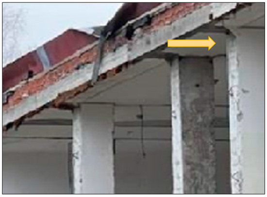
Figure 3.
Considerable dilapidation of the perimeter wall of the frame building (photo: Kubečková, D.).
2.1. Characteristics of a Post-Industrial Locality—Case Study
The Ostrava-Karvina region has an area of more than 170 km2. Regular black coal mining was initiated as early as 1787 by the “Wilczk” brothers. The first deep coal mine in the Ostrava-Karvina region was founded in 1852 by S.M. Rothschild (the mine is called “Hlubina” (Deep) in Czech and has been a national cultural monument of the Czech Republic since 2002). Further heavy industry was developed here, including coke plants, iron works, smelting, and chemical industries. After 1990, there was a decline in heavy industry in the CZ, with the closing of mines and related industries. Many premises and buildings remained without further use.
2.2. Characteristics of the Prefabricated Assembled Skeleton—Type Series ASCA
The prefabricated skeleton of the ASCA type series was used from the 1970s to 1989. After that year, major construction was no longer carried out.
The structure of the perimeter wall was composed of elements consisting of prefabricated parapet panels and prefabricated gable panels for the entire floor height. Panels based on lightweight concrete, aerated concrete panels, or slag concrete panels were used as material variants. The external wall was very often supplemented with tiles (ceramic brick tiles were often used). Lightweight concretes were typical for the Ostrava-Karvina region, because slag, as a waste material in the production of iron, was widely used in construction. The external prefabricated panels were th. 270–300 mm (in the gable and parapet), and their heat transfer coefficient reached values of 0.89 to 0.46 [W/(m2·K)]. According to the current requirements in 2024, the heat transfer coefficient requirement is 0.30 [W/(m2·K)] for the perimeter wall. It is clear that the perimeter walls of the ASCA skeletons are completely unsatisfactory (see Table 1).

Table 1.
Development of requirements for the heat transfer coefficient of walls [33].
2.3. Theoretical Starting Point for Renovations of the Perimeter Wall of Skeleton Structures
The main factor that contributes to thermal load in the building is the penetration of heat losses through its envelope elements. The thermal performance of the building and the amount of heat loss through its components depend on factors such as the details of the building envelope, thermal bridges and bonds, interfaces, materials used, and quality of insulation. Thermal insulation is essential to increase the energy efficiency of a building and reduce costs related to heating, ventilation, and air conditioning. An effective combination of high-tech design, taking into account the location and orientation of objects in space, the use of materials with unique properties, and modern technologies such as renewable energy systems and “smart” control systems, enables the construction of buildings with high energy efficiency and a small carbon footprint.
Today’s society is increasingly focused on the impact of buildings in relation to the environment, especially when it comes to the materials used. By incorporating ecologically clean and environmentally friendly building materials, we can achieve improved thermal and hygienic comfort, contributing to better environmental protection An energy-efficient building is designed to provide the necessary functions, comfort, and convenience with the least possible energy consumption. The entire building design process must strictly prioritize the achievement of the building’s specified energy efficiency.
Perimeter walls are an important part of the building envelope, providing users with thermal as well as acoustic comfort.
Perimeter walls have been divided into many types that can improve the energy efficiency of buildings according to the materials used. During the day, the temperature of the outer walls is significantly affected by the changing temperature of the outside air and solar radiation. This leads to fluctuations in the heat flux passing through the walls, which can ultimately affect the indoor environment. Improving insulation and optimizing wall and roof thickness can reduce energy consumption by up to 40%.
The improved thermal performance of building envelope can be achieved by increasing insulation, using high-performance products, and applying efficient designs [34]. The rate and direction of heat exchange through a building’s envelope depend on various factors, such as solar gain, indoor and outdoor temperatures, the thermophysical properties of materials, and the exposed surface area. The thermophysical properties of a material that affect the heat transfer rate include density, thermal conductivity, heat capacity, thermal resistance, thermal transmittance, and surface characteristics. In addition to the thermophysical properties, the thickness of the material used to construct the walls can also impact their heat storage capacity [35,36]. The algorithm for the thermal process calculations in this study is shown in Figure 4.
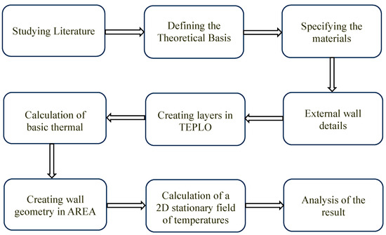
Figure 4.
The algorithm for thermal process calculations in this study.
The original external perimeter walls of skeleton structures are quite outdated, degraded, and completely unsatisfactory from the point of view of normative indicators in the field of thermal technology. Points of contact are always verified by diagnostics before designing a new external envelope (see Figure 5a). If the supporting structure of the skeleton is significantly degraded or in a state of emergency, we will decide based on the result of the static assessment and a complete renovation including the supporting structure or demolition. Figure 5b documents the energetic renovation of the perimeter wall.
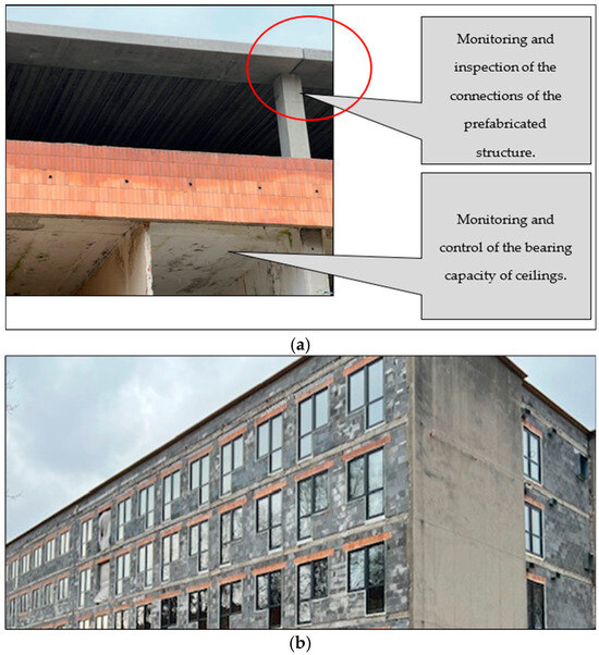
Figure 5.
A view of the renovation of the perimeter wall of the skeleton structure: (a) original outer shell (parapet panel with brick cladding); (b) new material variant (photo: Kubečková, D.).
Heat Transfer Conduction in Multilayered Walls
The external envelope of buildings consists of multilayered walls of different materials. The rate of steady heat transfer through composite walls can still be determined using the thermal resistance concept. Equivalent thermal circuits can be used for composite walls. Such walls may involve any number of series and parallel thermal resistances due to layers of different materials [37] (see Figure 6a,b). The general form of the heat equation, under steady-state conditions (there can be no change in the amount of energy storage), after additional simplifications of the general form, is given as follows (1) [37,38,39]:
where the terms , and are related to the net conduction heat flux into the control volume for the x, y, and z-coordinate directions. Also, is the rate at which energy is generated per unit volume of the medium (W/m3).
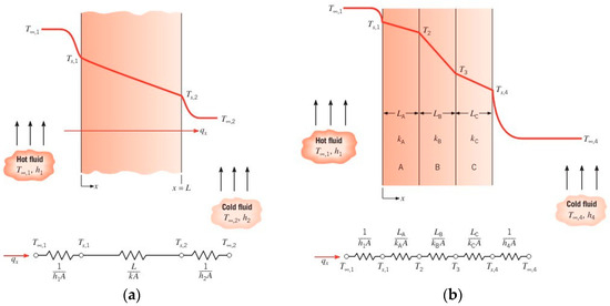
Figure 6.
Heat transfer process: (a) equivalent thermal circuit for a plane wall, (b) equivalent thermal circuit for a series composite wall [39].
The one-dimensional heat transfer rate for composite walls is given as follows (2) [39]:
the overall temperature difference, and the summation includes all thermal resistances; hence, (3) [39]:
where A is the area of the wall normal to the direction of heat transfer, L represents the length of each material in the wall, and k is the thermal conductivity (characteristic of the wall material) [W/(m·K)]. Also, the parameter h [W/(m2·K)] is the convection heat transfer coefficient. Alternatively, the heat transfer rate can be related to the temperature difference and resistance associated with each element (4) [39]:
With composite systems, it is often convenient to work with an overall heat transfer coefficient U with the unit [W/(m2·K)], which is defined by an expression analogous to Newton’s law of cooling. According to (5), there is a heat transfer area [m2], and is the temperature difference across the composite system [39]:
In some cases, the temperature in a medium varies mainly in two primary directions, and the variation in temperature in the third direction (and, thus, heat transfer in that direction) is negligible. For two-dimensional, steady-state conditions with no generation and constant thermal conductivity, this form is, from Equation (1) [39], Figure 7a for two-dimensional conduction and Figure 7b for two-dimensional heat transfer in a long rectangular bar (6).
and represent the changes in the heat flux gradient in the x-direction and y-direction.
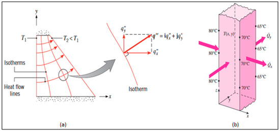
Figure 7.
Model situation: (a) two-dimensional conduction [37]; (b) two-dimensional heat transfer in a long rectangular bar [40,41].
According to Fourier’s law (Constitutive Equation), heat flux is proportional to the negative temperature gradient (7) [42]:
The heat flux/temperature gradient according to a 2D finite element for heat transfer problems is given as follows (9) [42]:
In Equations (7)–(9), Kxx, Kxy, and Kyy represent the thermal conductivities. For isotropic materials, Kxx = Kyy = K and Kxy = 0. The matrix [K] denotes the conductivity matrix.
2.4. External Wall
The case study focuses on heat transfer through different types of external walls (perimeter walls) and comparative thermal analyses of walls made of traditional and alternative building materials. Figure 8a–c and Table 2, Table 3 and Table 4 illustrate and present the characteristics of the wall materials. They are:
- Massive brick perimeter walls (variant 1);
- Perimeter wall composed of two or more layers (variant 2);
- Multi-layer perimeter walls (variant 3).
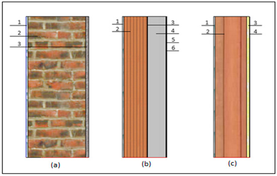
Figure 8.
The three basic configurations used for modelling the walls: (a) traditional external envelope (single-layer construction based on ceramic material); (b) conventional external envelope (composite construction, two or more layers); (c) proposed external envelope (composite structure, multi-layered). See also Table 2, Table 3 and Table 4.
Figure 9 provides an overview of building structures in CZ during the last century, with an example of the post-industrial locality Ostrava. A field observation of post-industrial areas indicates that the structures of the buildings and their envelopes of walls are generally similar, with solid brick walls of significant thickness. Table 2 documents the characteristics of the selected building’s physical parameters.
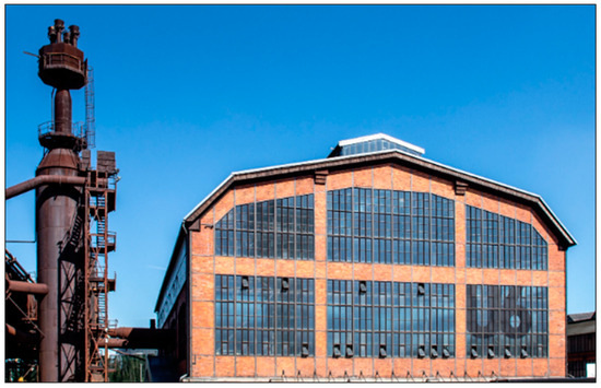
Figure 9.
A building of a post-industrial location from the beginning of the last century, based on the example of the city of Ostrava (CZ) and a characteristic brick outer shell [43].
Table 2.
Characteristics of traditional massive external wall materials (in the last century, CZ), V1.
Table 2.
Characteristics of traditional massive external wall materials (in the last century, CZ), V1.
| NO. | Wall Material Layers | Thickness d [m] | Density ρ [kg/m3] | Thermal Conductivity [W/m·K] | [m2·K/W] |
|---|---|---|---|---|---|
| 1 | Internal lime plaster | 0.015 | 1600 | 0.870 | 0.0172 |
| 2 | Solid bricks | 0.440 | 1700 | 0.800 | 0.5500 |
| 3 | External lime–cement plaster | 0.025 | 2000 | 0.990 | 0.0253 |
Figure 10 documents the variants of the perimeter wall for residential housing projects and for buildings of civic amenities of the city. This variant is among the technologies often used after 2000. The application of the ETICS composite is widespread. Table 3 documents the characteristics of the selected building’s physical parameters.
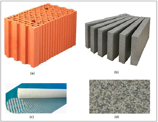
Figure 10.
Component layers of the ETICS facade system for residential buildings in CZ: (a) product for external perimeter masonry with marking Porotherm 24 Profi; (b) thermal insulation from facade polystyrene gray with marking EPS 70 NEO; (c) reinforcement layer; (d) mosaic plaster [44,45,46,47].
Table 3.
Characteristics of conventional external wall materials for residential buildings and civic amenity buildings in CZ, V2.
Table 3.
Characteristics of conventional external wall materials for residential buildings and civic amenity buildings in CZ, V2.
| NO. | Wall Material Layers | Thickness d [m] | Density ρ [kg/m3] | Thermal Conductivity [W/m·K] | [m2·K/W] |
|---|---|---|---|---|---|
| 1 | Internal lime plaster | 0.010 | 1600 | 0.716 | 0.0140 |
| 2 | Masonry From Porotherm 24 Profi Blocks | 0.240 | 800 | 0.290 | 0.8276 |
| 3 | ETICS adhesive layer | 0.003 | 1300 | 0.700 | 0.0043 |
| 4 | EPS 70 NEO | 0.150 | 16.00 | 0.033 | 4.5455 |
| 5 | ETICS reinforcement layer | 0.003 | 1000 | 0.750 | 0.0040 |
| 6 | Penetration + Mosaic plaster | 0.003 | 1750 | 0.700 | 0.0043 |
Figure 11 documents the multi-layer composite construction of the perimeter wall based on heat-insulating materials, perlite and aerogel. Table 4 documents the characteristics of the selected building’s physical parameters.
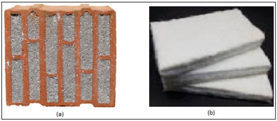
Figure 11.
Component layers of the proposed external wall: (a) hollow brick unit filled with perlite insulation; (b) aerogel fibrous composite (AFC) [44,45,46,47].
Table 4.
Characteristics of proposed external wall material using aerogel fibrous composites and hollow brick filled with perlite insulation—example of a variable solution, V3.
Table 4.
Characteristics of proposed external wall material using aerogel fibrous composites and hollow brick filled with perlite insulation—example of a variable solution, V3.
| NO | Wall Material Layers | Thickness d [m] | Density ρ [kg/m3] | Thermal Conductivity [W/m·K] | [m2·K/W] |
|---|---|---|---|---|---|
| 1 | Internal lime plaster | 0.010 | 1600 | 0.7160 | 0.0140 |
| 2 | Hollow brick filled with perlite | 0.300 | 653.15 | 0.0900 | 3.3333 |
| 3 | AFC | 0.020 | 266.20 | 0.0208 | 0.9615 |
| 4 | Penetration + Mosaic plaster | 0.003 | 1750 | 0.7000 | 0.0043 |
The comparison indicates (Table 2, Table 3 and Table 4) that, in terms of the energy renovation of buildings, an important aspect is the physical value of the coefficient of thermal conductivity λ [W/mK]. It expresses the ability of an isotropic material to retain heat at a given temperature. The coefficient of thermal conductivity depends on several factors (for example, dependence on humidity, bulk density, and thickness of the material). In current energy-efficient building renovations, we mainly apply polystyrene or mineral wool. Both materials achieve relatively effective values of the coefficient of thermal conductivity, around 0.030 [W/m·K] to 0.035 [W/m·K]. However, these insulating materials age over time and can create various defects in the perimeter walls. As reported by [48,49,50,51,52], among the defects of buildings for housing and civic equipment of the city which have undergone energy rehabilitation approximately 20 years after the application of ETICS with thermal insulation based on polystyrene or mineral wool, defects related to the moisture issue of ETICS appear. These manifest as, for example, leakage through leaks in ETICS (shrinkage of the insulator occurs over time, and cyclic stressing, formation of micromud, and biodegradation manifestations in ETICS are obvious).
Aerogels are another option for energy renovations. Aerogel is widely recognised as a highly effective insulating material with the potential to greatly enhance the thermal insulation performance of building walls. It can be utilised in different forms, such as aerogel plasters (AP), aerogel fibrous composites (AFC), and aerogel concrete (AC), in practical engineering applications [53]. Hollow bricks filled with perlite insulation are used in this study. This helps to increase the thermal resistance of the vertically perforated bricks by filling the spaces with perlite insulation. As a result of this process, a very low thermal conductivity value is achieved [54]. For documentation: hollow bricks filled with perlite insulation are used for the external wall, and to increase the thermal resistance of this vertically perforated brick, the spaces are filled with perlite insulation. Thanks to this process, a very low value of thermal conductivity is obtained. The indisputable advantage of aerogel is the achievement of thermal insulation efficiency at a minimum thickness; the coefficient of thermal conductivity reaches λ = 0.016 [W/m·K]. Aerogel is also technologically comfortable, it is easy to work with, and we can glue it, although on larger surfaces we prefer anchoring with dowels. However, the price of airgel significantly exceeds the price of thermal insulation on the construction market, such as facade polystyrene, facade polyurethane boards, facade phenolic boards, and foam glass. Therefore, with airgel, we prefer to apply it to critical places, such as thermal bridges, joints, etc.
Variant Solution of the Perimeter Wall for the ASCA Skeleton
The TEPLO 2017 (Heat) and AREA 2017 modules from SVOBODA software (Version 2017.3) are used to assess the thermal performance of building envelope details in this study. The TEPLO 2017 program allows for the calculation of basic thermal technical parameters of building structures in compliance with EN ISO 6946 [53], EN ISO 13788 [54], ČSN 730540 [55], and STN 730540 [56]. The program calculates the thermal resistance, heat transfer coefficient, internal surface temperature, temperature factor, thermal attenuation, drop in contact temperature of the floor structure, and the annual balance of condensed and evaporated water vapor.
The AREA 2017 program allows for the calculation of a two-dimensional stationary field of temperatures and partial pressures of water vapor, as well as the approximate annual balance of water vapor in two-dimensional building details. The results also encompass the lowest internal surface temperatures, temperature factors, and heat flows. The program also provides additional calculation modules for calculating the heat transfer coefficient of window constructions and lightweight external surfaces according to EN ISO 10077 and EN 12631, for calculating linear heat transfer factors according to EN ISO 10211, and for calculating the temperature factor of 3D thermal bridges and connections according to EN ISO 10211-2 (2002) and according to the manual [57,58], standards, and code [55,56,59,60,61,62].
The finite element method (FEM) is utilized to calculate the stationary two-dimensional field of temperatures and partial pressures of water vapor. It is possible to solve the details:
- (A)
- Details covered by a mesh of up to 200 × 200 axes, containing a maximum of 40,000 unknowns, which are composed of a maximum of 200 rectangular homogeneous regions and have a maximum of 200 boundary conditions.
- (B)
- Details with a generally curvilinear boundary containing up to 40,000 unknowns, up to 200 different materials, and 200 different boundary conditions.
Figure 12 depicts the energy loss of multilayered walls. Walls typically consist of three layers: internal plaster, a solid wall, and an external wall. To minimise energy loss, an insulation layer should be added, which can be composed of different layers. Additionally, Figure 9 specifies the boundary conditions: Ti represents the inside temperature (20 °C), to represents the outside temperature Te (−16 °C), Rsi is the thermal contact resistance inside (0.13 [m2·K/W]) according to DIN 6946 and ČSN 730540-3 (CZ Code), and Rse is the thermal contact resistance outside (0.04 [m2·K/W]) according to DIN 6946 (DIN Code) and ČSN 73 0540-3 (CZ Code).
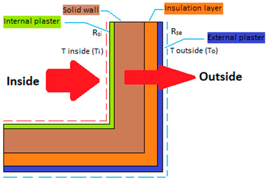
Figure 12.
Schematic view of boundary condition.
3. Results and Discussion
This case study analyses three multilayered walls according to the climate of the Czech Republic. The primary indicators of wall structures include the resistance to heat transfer and the heat transfer coefficient, which determine the energy efficiency of buildings. The results of the simulation model were determined using the algorithm in Figure 13, Figure 14 and Figure 15 and are displayed in Figure 16.
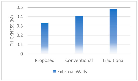
Figure 13.
Thickness [m] of various types of walls.
Figure 13 illustrates that one of the primary benefits of the proposed wall is the reduction in wall thickness, which is crucial in terms of the architectural and structural aspects of buildings. The thickness of the proposed walls is 23% lower compared to the conventional wall, and this value is 44% lower than that of traditional walls. Figure 14 shows that proposed and conventional walls reduce the dead load of the structure, potentially leading to a decrease in the size of the foundation, supporting columns, and beams. The proposed and conventional walls weigh the same per square meter. Their weight is 3.70 times less than traditional walls.
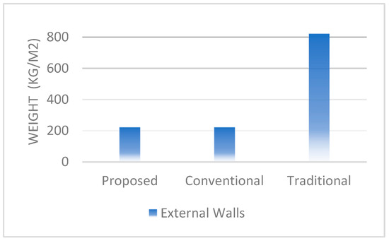
Figure 14.
Weight [kg/m2] of various types of walls.
In Figure 15, the U-value represents the inverse sum of the resistances of each building material and surface resistances to the outer and inner faces of the material build-up of the element. The analysis shows that the conventional wall with a 150 mm layer of EPS 70 NEO thermal insulation achieves a lower U-value compared to the proposed wall. This indicates that the conventional wall provides better thermal resistance and reduces heat transfer more effectively. Despite this, the proposed wall—with its smaller thickness—also demonstrates strong thermal performance, achieving a U-value only 1.2 times higher than the conventional wall, which utilizes a 6-layer system. Both the conventional and proposed walls significantly outperform traditional walls, with U-values reduced by factors of 6.55 and 5.40, respectively. This substantial improvement highlights the critical role of advanced insulation materials in enhancing thermal performance. The impact of U-value and thickness on heat distribution is significant:
- Thermal comfort: walls with lower U-values create a more consistent and stable indoor environment by minimizing heat loss in cold conditions and heat gain during warmer periods. This helps to maintain a uniform temperature throughout the building.
- Thermal resistance and material efficiency: the proposed wall achieves relatively low U-values despite its reduced thickness, highlighting the efficiency of advanced insulation materials. The balance between material innovation and wall thickness directly affects thermal performance.
- Energy efficiency: Lower U-values reduce the demand on heating and cooling systems, leading to reduced energy consumption and operational costs. Lower U-values in both designs reduce energy consumption, but the proposed wall’s thinner structure offers additional benefits, such as material savings and space optimization, while maintaining satisfactory thermal resistance.
- Heat distribution uniformity: improved insulation ensures even heat distribution within the building, avoiding localized cold or hot spots that can occur with poorly insulated walls. Both designs effectively limit heat transfer, contributing to more stable indoor temperatures and reducing the likelihood of cold or hot spots.
By effectively reducing the U-value, modern insulation techniques not only improve energy efficiency, but also enhance thermal comfort and heat distribution, making them a cornerstone of sustainable and efficient building design. Furthermore, while wall thickness is a key factor in reducing U-values and improving thermal performance, advancements in insulation materials enable even thinner walls, such as those of the proposed design, to achieve competitive U-values and ensure energy-efficient, uniform heat distribution. This balance between thickness and material innovation is crucial for sustainable building design.
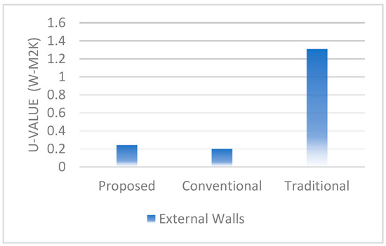
Figure 15.
U-value [W/(m2·K)] of various types of walls.
Figure 16a–c illustrate the temperature distribution within three different walls. The temperature gradient varies within each layer as a result of changes in conductivity. Increasing conductivity results in a decreased temperature gradient. The conventional and proposed walls have greater thermal resistance compared to traditional walls, and this leads to less transfer of heat and cold. The traditional wall in the corner region exhibits significant thermal bridging, characterized by lower temperature zones. In contrast, the conventional wall displays higher surface temperatures at the corner, suggesting marginally better insulation at the junction. The proposed wall, despite its thinner design, demonstrates effective insulation performance, as the inner surface temperature remains closely aligned with the indoor environment’s temperature. However, the conventional wall’s higher surface temperatures at the corner further indicate superior thermal resistance compared to the proposed design.
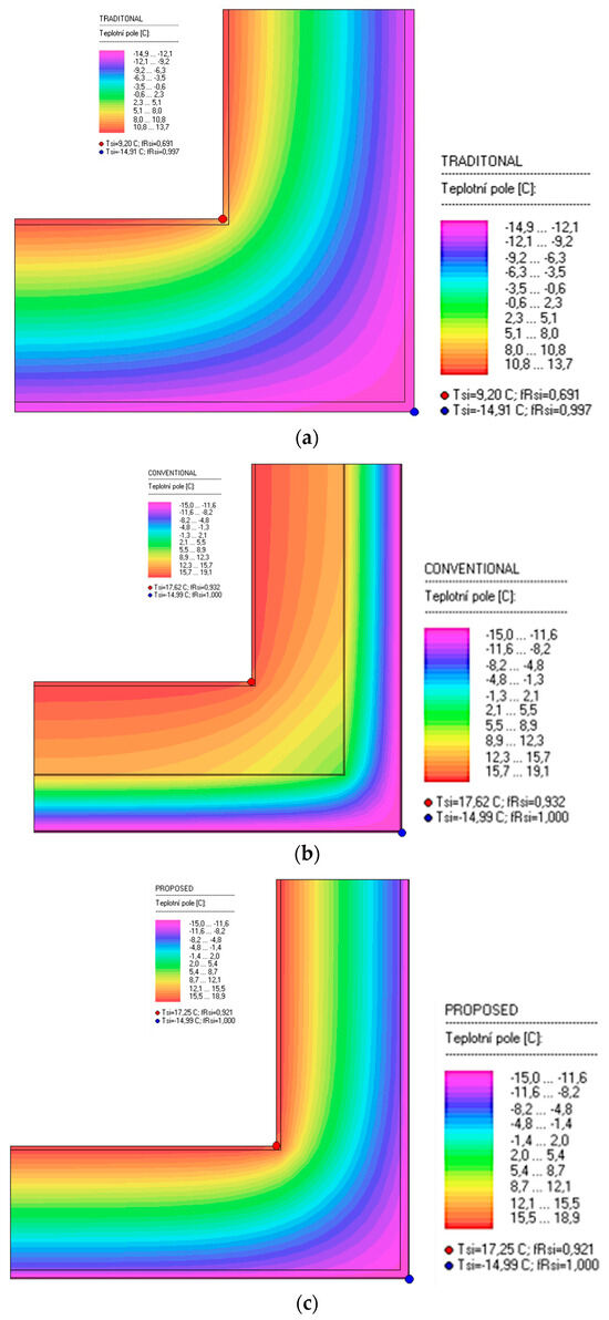
Figure 16.
Temperature distribution: (a) for the traditional wall; (b) for the conventional wall; (c) for proposed wall. (Note: Evaluation of the critical part of the perimeter structure by the 2D temperature field allows us to present the least favourable technological tolerances of the shape and material solution).
The results show that the variability of the material solution for the perimeter walls of ASCA-type buildings in post-industrial areas can differ with a link to the energy rehabilitation of these buildings. However, provided that the results comply with standard regulations and legislation. Variant material solutions and compositions 2 and 3 meet this requirement. From a cost and economic perspective, variant 2 (V2) is better because it is more affordable. For example, the price of 1 XPS board (dimensions: 30–120 × 600 × 1250 mm) for 1 m2 is CZK 30–120 (EUR 1.2–4.8), and the price of 1 board of aerogel (dimensions: 40 × 100 × 1500 mm) is around CZK 2800 (EUR 112).
This supports the EU strategy, which states that older buildings need to undergo energy rehabilitation based on the result of a passport in an economically efficient manner. Variant 3 (V3) would also be a positive benefit. But here, the cost aspect of energy rehabilitation is far greater.
A major advantage is that both variant solutions (V2, V3) are suitable for the ASCA-type skeletons, which are widespread in the post-industrial territory of the Ostrava-Karvina region. The variability of this skeleton in terms of the structural arrangement (column–beam–ceiling slabs) is highly favourable for various new typological uses. This gives added value to these skeletons. They can be used especially as administrative buildings during energy renovations.
It is impossible to evaluate ASCA-type series skeletons separately with regard to the potential for achieving climate neutrality. These skeletons currently have a lifespan of more than 50 years. Concrete mixes with reinforcement have been used for the production of prefabricated elements in the last century (production of prefabricated elements column–beam–ceiling slab perimeter panels). However, if we remove the original prefabricated perimeter wall and replace it with a new perimeter shell (in the V2 or V3 variant) as part of energy renovations, we will achieve energy savings and also contribute to reducing the carbon footprint because we understand the improvement of the energy performance of buildings as one of the aspects that contribute to the solution of reducing carbon emissions. A similar positive solution can be found in the energy rehabilitation of the panel residential housing in the CZ from the second half of the last century (Appendix A).
Our effort within the framework of our research task [63] and our results also support the results of studies by other authors. The fact that skeletal structures of post-industrial settlements are desirable to reconstruct is supported, for example, by reference [64]. The results of this work show that skeletal structures from the 2nd half of the last century are often neglected for reconstruction. This is regardless of the fact that skeletal spatial structure is highly modular and usable. In post-industrial areas, it can become an element that, after reconstruction, becomes part of the meaning of cultural heritage. This study concludes with the sentiment: “…skeletal spatial structures can meet many basic building requirements of modern societies, especially those facing environmental problems, all while allowing for design flexibility and mass customization…”.
Other studies address the issue of skeletal structures historically based on stone, wood, or masonry structures, which bear the characteristics of skeletal systems [65].
The fact that the European building stock was mostly built in the 20th century and is characterized by, among other things, high energy demands is highlighted in the new study [66]. Integrated modernization interventions are, therefore, urgently needed and desirable. In this interesting study, renovation interventions for reinforced concrete buildings are proposed in order to improve their energy efficiency and their structural performance (e.g., in the area of seismicity). The aim of the reconstruction work is an integrated reconstruction which is focused on structural, architectural and energy improvements. With regard to the energy area and the replacement of the external envelope, energy retrofitting with multifunctional prefabricated modular facades based on wood was presented, which was evaluated as being able to reduce heat consumption by an average of 84% in different climate zones. The proposed integrated solution is presented in the study as a promising alternative to demolition and reconstruction, providing deep energy renovation and structural modernization; avoiding unavoidable waste production, additional energy consumption, and CO2 emissions; and enabling sustainable renovation of the existing building stock. The results support our argument that contemporary society is increasingly emphasizing the environmental impact of buildings.
It is clear that current trends in building external envelopes, both for new buildings and for buildings intended for renovation, will be directed towards integrated facades. For example, ref. [67] defines areas for the energy performance of buildings using the integration of energy systems into the building structure, with the aim of advantageous prefabrication for production (production of prefab). The approach is based on the principle of sustainable construction. A new approach to the design, implementation, and operation of buildings and urban areas is proposed in such a way as to achieve a wide spectrum of functional, economic, environmental, social, and cultural requirements.
However, our argumentation based on simulation results suggests that the envelopes of frame structures can be successfully reconstructed with multi-layer walls in a suitable composition, and energy efficiency of the envelope can be achieved. This is in accordance with legislative documents in the Czech Republic. The Building Act [68] states, among other things, that energy reconstructions should be carried out in an appropriate and economically and technologically acceptable manner. The presented solution may be a promising alternative to the demolition of the entire structure, which would inevitably lead to excessive waste production, additional energy consumption, and CO2 emissions. This would contradict the EU strategic documents that emphasize climate neutrality by 2050.
4. Conclusions
There are numerous abandoned buildings which present a unique opportunity for conversion into residential or administrative premises due to their potential for revival after the winding down of industrial activities. The conversion of these properties for residential or administrative use is a way to increase housing supply, administrative buildings, and zero-emissions buildings; reduce long-term energy costs and volatility; improve affordability; and ultimately create efficiency, thereby contributing to climate goals.
The results show that the conventional and proposed walls have greater thermal resistance compared to traditional walls, leading to lower heat and cold transfer. Due to the greater thickness of conventional walls compared to those proposed, there is slightly less heat transfer, but this difference is insignificant. The proposed insulation materials decrease heat transfer because of low thermal conductivity and also have lower weight, density, and lower thickness, which can be a major priority when converting industrial buildings into residential or administrative buildings.
In terms of heat transfer, the proposed walls, composed of hollow bricks filled with perlite and AFC, have almost the same characteristics as conventional walls. Another of the main advantages of the proposed wall is the reduction in wall thickness, which is crucial for the architectural and structural aspects of buildings.
The thickness of the proposed walls is 23% lower compared to the conventional walls and 44% lower compared to traditional walls. Also, the proposed and conventional walls reduce the structural dead load. The weight of these walls is 3.77 times less than that of traditional walls.
The conventional wall with a 15 cm thick layer of EPS insulation has a slightly lower U-value in comparison with the proposed wall, but the difference is insignificant, and it should be considered that the separate layer of insulation of the proposed wall is 2 cm. Both the proposed and conventional walls have U-values approximately 2.5 times lower than traditional walls.
The proposed wall, due to its light weight and reduced thickness, as well as its excellent thermal insulation performance, can be a suitable choice for external walls in the post-industrial locality region.
From the aforementioned experimental activity, it follows that buildings in the skeleton construction system from the 1970s that were used for industrial operation can very well be energetically rehabilitated. Reorganizations have a positive impact on the company and can be a very good motivation for new investors.
A set of recommendations can be applied for the new use of buildings (frame construction type) in post-industrial locations:
- Impact of the wall, roof, and window material on reducing energy costs in buildings in brownfields compared to the original state.
- Research on new innovative building materials and wall construction that can reduce energy consumption.
- Impact of the new building material on thermal bridge and system identification process for building energy simulation.
At the same time, it turns out that, for buildings in post-industrial locations and their energy renovations, it is necessary to consider the motivation to undertake reconstruction works, taking into account the value of the industrial heritage of both the area and the building. The time frame will encompass post-industrial cities and buildings that have a contextual overlap with the transformative years of the 1990s. And that post-industrial location is the Ostrava-Karvina region. Our effort leads, within the framework of our research task to the definition of meaningful energy-efficient renovations that relate to industrial buildings of typical character, whereby prefabricated skeletons from the 2nd half of the last century are assembled.
Author Contributions
H.A.: writing—original draft, project administration, methodology, investigation, visualization, data curation, software, validation. D.K.: writing—review and editing, formal analysis. O.K.M.: resources. K.M.: resources. All authors have read and agreed to the published version of the manuscript.
Funding
This work was supported by the Student Grant Competition VSB-TUO. The registration number of the project is [SP2024/011] and Institutional support FCE VSB-TUO n. 1101, 2104 for year 2024.
Data Availability Statement
The raw data supporting the conclusions of this article will be made available by the authors on request.
Conflicts of Interest
The authors declare the following financial interests/personal relationships which may be considered as potential competing interests: Hamed Afsoosbiria et al. report that article publishing charges were provided by VSB-TUO. Darja Kubečková reports a work relationship with VSB-TUO. All authors declare that they have no known competing financial interests or personal relationships that could have appeared to influence the work reported in this paper.
Appendix A
- (a)
- Kubečková, D.: Regeneration of Panel Housing Estates from the Perspective of Thermal Technology, Sustainability and Environment Cotext (Case Study of the City of Ostrava, Czech Republic). Sustainability 2023. Vol. 15 (11), 8449. pp. 1–25. DOI: https://doi.org/10.3390/su15118449. ISSN 2071-1050. (Article. Special Issue: Sustainability Energy Systems in Buildings).
- (b)
- Kubečková, D.: The Quality of ETICS in the Context of Energy and Social Changes (Case study). Sustainability 2022. Vol. 14 (6), 3135. pp. 1–21. Article. DOI: https://doi.org/10.3390/su14063135.
- (c)
- Kubečková, D., Vrbová, M.: Historical Development of Thermal Protection of Prefab Residential Housing and Its Future, an Example of the Czech Republic. Energies 2021. Vol. 14 (9). pp. 1–21. Article. DOI: https://doi.org/10.3390/en14092623.
References
- Beran, L.; Kristian, M. Industrial Architecture, Designer and Plans Beran; Research Centre for Industrial Heritage: Prague, Czech Republic, 2021; ISBN 978-80-01-06890-8. [Google Scholar]
- Fragner, B.; Zikmund, J.; Červinka, J. Industrial Contexts/Place_Form_Programme: The Architecture of Conversion 1990–2005–2015–2020; Research Centre for Industrial Heritage: Prague, Czech Republic, 2021; ISBN 978-80-01-06807-6. [Google Scholar]
- Charlson, J. The Introduction of Brownfield Land Registers in England. Plan. Pract. Res. 2020, 36, 216–229. [Google Scholar] [CrossRef]
- Wan, Y.S.; Chen, S.; Liu, J.; Jin, L. Brownfield-related studies in the contex’t of climate change: A comprehensive review and futurés prospects. Helion 2024, 10, e25784. [Google Scholar] [CrossRef] [PubMed]
- Kolejka, J.; Klimánek, M. Vymezení a typologie postindustriální krajiny Česka. Gegrafie 2012, 117, 289–293. [Google Scholar] [CrossRef]
- Ruelle, C.; Halleux, J.-M.; Teller, J. Landscape Quality and Grownfiled Regenration: A Community Investigation Approach Inspired by Landscape Preference Studies. Landsc. Res. 2013, 38, 75–99. [Google Scholar] [CrossRef]
- Brownfields. Available online: https://www.brownfieldy.cz/app/uploads/2024/10/sbornik-brownfieldy-2024.pdf (accessed on 30 October 2024).
- Kubeckova, D. Member of CEZ J17/98271200018 “Research Methods of Regeneration of the Devastated Industrial Areas”, Co-Research of “Methodology of Evaluation Objects on the Industrial Areas Devastated” (1994–2004), Research Project. Available online: www.vsb.cz (accessed on 8 December 2024).
- Kadár, K. Brownfield Cities in Hungary; Regional Science Association of Subotica: Subotica, Serbia, 2011; Volume 3, pp. 123–141. [Google Scholar]
- Rebenik, L.; Vojvodíková, B.; Lampic, B. Brownfield Data and Database Management-The Key to Address Land Recycling. Land 2023, 12, 252. [Google Scholar] [CrossRef]
- Kubečková, D.; Kubenková, K.; Galda, Z. Technical Sheets CIDEAS (2004–2011). FCE VSB-TUO. Available online: https://www.fast.vsb.cz/en/search?query=Technical%20Sheets%20CIDEAS (accessed on 8 December 2024).
- Buildings in the Fit for 55 Package for a Climate Neutral Economy in 2050. Euroace, Energy Efficient Buildings (Last Update May 2023). Available online: https://efficientbuildings.eu/buildings-in-the-fit-for-55-package-for-a-climate-neutral-economy-in-2050/ (accessed on 28 July 2024).
- Energy Performance of Buildings Directive (EPBD), Implementation Guide. Available online: https://efficientbuildings.eu/wp-content/uploads/2024/10/Efficient-Buildings-Europe-Implementation-Guide-2024_online-1.pdf (accessed on 30 October 2024).
- Energy Efficiency. Council Directive of the European Parliament 2012/27/EU z 25.10.2012. 2012. Available online: https://eur-lex.europa.eu/legal-content/EN/NIM/?uri=celex:32012L0027 (accessed on 1 March 2021).
- Directive no. 264/2020, on the Energy Performance of Buildings. 2020. Available online: https://energy.ec.europa.eu/topics/energy-efficiency/energy-efficient-buildings/energy-performance-buildings-directive_en (accessed on 8 December 2024).
- Delivering the European Green Deal. 2021. Available online: http://energy.ec.europa.eu (accessed on 28 July 2024).
- Regulation of the European Parliament and the Council (EU) 2021/1119 (“Climate Law”). Available online: https://eur-lex.europa.eu/legal-content/EN/TXT/?uri=CELEX%3A32021R1119 (accessed on 8 December 2024).
- EPBD Energy Performance of Buildings Directive (Include Recast). Commission Proposal. Available online: https://www.eurovent.eu/issues/energyperformanceofbuildings/ (accessed on 28 July 2024).
- Hajek, P. Structures of Civil Engineering II; CTU: Prague, Czech Republic, 2002. [Google Scholar]
- Type Basis of the Structural System of the Assembled Skeleton MS-OB; Research and Development Institute of Civil Engineering in Ostrava: Ostrava, Czech Republic, 1983; Volume IV.
- Jirka, V. Ground Construction II, Structural Systems of Multi-Storey Buildings, Column Structures; CTU: Prague, Czech Republic, 2016. [Google Scholar]
- Čapek, M.; Růžička, M. Assembled Concrete Structures; SNTL: Prague, Czech Republic, 1976. [Google Scholar]
- Tywoniak, J. Construction-Energy Concepts of Buildings in Social Contexts. Available online: https://stavba.tzb-info.cz/nizkoenergeticke-stavby/21825-stavebne-energeticke-koncepce-budov-ve-spolecenskych-souvislostech (accessed on 8 December 2024).
- Efficient Building Europe. Implement, Industrialise, Imagine the Future of Building Renovation. Available online: www.efficientbuildings.eu (accessed on 21 May 2019).
- Hlaváček, E. Architecture of Movement and Transformation; Odeon: Prague, Czech Republic, 1985. [Google Scholar]
- Řehánek, J. Thermal and Energy Properties of Buildings; Grada: Prague, Czech Republic, 2002. [Google Scholar]
- Šála, J.; Keim, L.; Svoboda, Z.; Tywoniak, Z. Thermal Protection of Buildings; IC ČKAIT: Prague, Czech Republic, 2008. [Google Scholar]
- EPBD-Implementation Guide. Available online: www.efficientbuildings.eu (accessed on 20 November 2024).
- Witzany, J. Concept of the further direction of building construction. Buildings 2021, 11, 16–22. [Google Scholar]
- Witzany, J. Construction and Technology for the Completion of Cities and Municipalities; Report for the Ministry of Industry CZ; FCE CTU: Prague, Czech Republic, 1990. [Google Scholar]
- Horáček, M. Prefab Buildings; Publishing House of Technical Literature Prague: Prague, Czech Republic, 1997. [Google Scholar]
- Map Documents. Available online: http://www.mapy.cz (accessed on 30 October 2024).
- Kubečková, D.; Vrbová, M. Historical Development of Thermal Protection of Prefab Residential Housing and Its Future, an Example of the Czech Republic. Energies 2021, 14, 2623. [Google Scholar] [CrossRef]
- Vaseghi, A.; Capano, C.D. Comparative analysis of insulation strategies for improving the thermal performance of wall to parkade suspended slab. Energy Built Environ. 2023, 6, 147–160. [Google Scholar] [CrossRef]
- Denmukhammadiev, A.; Pardaev, A.; Kucharov, F.; Nasimova, L. Electronic-physical model that determines thermal conductivity of walls made of various materials. In E3S Web of Conferences; EDP Sciences: Les Ulis, France, 2023; Volume 401. [Google Scholar]
- Toure, P.M.; Dieye, Y.; Gueye, P.M.; Faye, M.; Sambou, V. Influence of envelope thickness and solar absorptivity of a test cell on time lag and decrement factor. J. Build. Phys. 2020, 43, 338–350. [Google Scholar] [CrossRef]
- Bergman, T.L.; Lavine, A.S.; Incropera, F.P.; DeWitt, D.P. Fundamentals of Heat and Mass Transfer, 8th ed.; Wiley: Hoboken, NJ, USA, 2018; ISBN 978-1-119-35388-1. [Google Scholar]
- Çengel, Y.A. Chapter 3, Steady Heat Conduction. In Heat Transfer: A Practical Approach, 2nd ed.; McGraw-Hill: New York, NY, USA, 2003. [Google Scholar]
- Çengel, Y.A. Chapter 2, Heat Conduction Equation. In Heat Transfer: A Practical Approach, 2nd ed.; McGraw-Hill: New York, NY, USA, 2003. [Google Scholar]
- Steady Heat Conduction, Wright State University. Available online: http://cecs.wright.edu/~sthomas/htchapter03.pdf (accessed on 30 September 2024).
- Heat Conduction Equation, Wright State University. Available online: https://cecs.wright.edu/~sthomas/htchapter02.pdf (accessed on 30 September 2024).
- Finite Elements for Heat Transfer Problems, University of Florida. Available online: https://www.wiley.com/en-us/The+Finite+Element+Method+in+Heat+Transfer+Analysis+-p-9780471943624 (accessed on 30 September 2024).
- Photo. Available online: http://www.investicniostrava.cz (accessed on 3 November 2024).
- Radoslav, P.; Ján, R. Study of Summer Overheating the New Masonry Self-Insulating Block. In Proceedings of the EnviBUILD 2019, Bratislava, Slovakia, 7 November 2019; pp. 134–139. [Google Scholar]
- Available online: https://www.tenapors.lv/en/product/tenapors-neo-eps-70-en (accessed on 30 September 2024).
- Available online: https://www.fiberglassscreen.org/fiberglassmesh/fiber-mesh-reinforcing.htm (accessed on 30 September 2024).
- Available online: https://baumaster.eu/en/products/thermal-insulation/mosaic-plaster (accessed on 30 September 2024).
- Yang, J.; Wu, H.; Liang, Y.; Cen, J.; Zhang, X. A Comparative Assessment of Different Aerogel-Insulated Building Walls for Enhanced Thermal Insulation Performance. Gels 2023, 9, 943. [Google Scholar] [CrossRef] [PubMed]
- Zukowski, M.; Haese, G. Experimental and numerical investigation of a hollow brick filled with perlite insulation. Energy Build. 2010, 42, 1402–1408. [Google Scholar] [CrossRef]
- Kubečková, D. Perspectives and sustainable urban development of panel housing estates in industrial areas. In Proceedings of the 6th International Multidisciplinary Scientific Conferences on Social Science & ART SGEM 2019, Vienna, Austria, 11–14 April 2019; Conference Proceedings. Volume 6, pp. 455–465. [Google Scholar] [CrossRef]
- Jasiczak, J.; Girus, K. Maintenance and durability of the concrete externl layer of curtain walls in prefabricated technological Poznan large panel system. World Multidisciplinary Civil Engineering-Architecture-Urban Planning Symposium (WMCAUS 2018). IOP Conf. Ser. Mater. Sci. Eng. 2018, 245, 032015. [Google Scholar] [CrossRef]
- Kubečková, D. Expert’s Archive (Own). 2015–2023. Available online: http://www.justice.cz (accessed on 20 October 2024).
- ČSN EN ISO 6946; Tepelné Vlastnosti Konstrukcí a Budov—Tepelný Odpor a Součinitel Prostupu Tepla—Výpočtová Metod. ČNI Praha: Prague, Czech Republic, 2008.
- ČSN EN ISO 13788; Tepelně Vlhkostní Chování Konstrukcí—Stanovení Vnitřní Povrchové Teploty pro Vyloučení Kritické Povrchové Vlhkosti a Určení Rizika Vnitřní Kondenzace. ČNI Praha: Prague, Czech Republic, 2013.
- ČSN 730540; Thermal Protection of Buildings, Part 1, 3 and 4. Czech Technical Standard: Prague, Czech Republic, 2007.
- STN 730540; Thermal Protection of Buildings, Part 2 and 3. Slovak Office of Standards Metrology & Testing (UNMS): Bratislava, Slovakia, 2012.
- Manual for TEPLO 2017 Program. Available online: http://www.vsb.cz/fast (accessed on 30 October 2024).
- Manual for AREA 2017 Program. Available online: http://www.vsb.cz/fast (accessed on 30 October 2024).
- ČSN EN ISO 10077-1; Thermal Behavior of Windows, Doors and Shutters—Calculation of the Heat Transfer Coefficient—Part 1. Czech Technical Standard: Prague, Czech Republic, 2007.
- ČSN EN ISO 10077-2; Thermal Behavior of Windows, Doors and Shutters—Calculation of the Heat Transfer Coefficient. Czech Technical Standard: Prague, Czech Republic, 2012.
- ČSN EN ISO 12631; Thermal Behavior of Light Outer Skins—Calculation of the Heat Transfer Coefficient—ČSN. Czech Technical Standard: Prague, Czech Republic, 2012.
- ČSN EN ISO 10211; Thermal Bridges in Building Structures—Heat Flows and Surface Temperatures—Detailed Calculations. Czech Technical Standard: Prague, Czech Republic, 2009.
- Afsoosbiria, H.; Kambole Musenda, O. Energy Efficient Solutions and Strategies for Different Types of Buildings. VSB-TU Ostrava, Research Work, n. SP2024/011. 2024. Available online: https://www.fast.vsb.cz/en/research/projects/2020-2024/?projectDetailId=679035383&fromPage=/en/research/projects/2020-2024/index.html (accessed on 8 December 2024).
- Maalek, S.; Maalek, R.; Maalek, B. Skeletal Space Sturctures Systems: Select Areas of Opportunity to Achieve Sustainability in Construction. Sustainability 2024, 15, 13288. [Google Scholar] [CrossRef]
- Alioglu, E.F.; Alper, B. The skeletal and heaped characteristic of traditional masonry structure. Int. Conf. Struct. Stud. Repairs Maintenace Herit. Archit. XI 2009, 109, 151–159. [Google Scholar] [CrossRef]
- Sebastiani, I.; D’Amore, S.; Pinotti, R.; Pampanin, S. Integrated rehabilitation of reinforced concrete buildings: Combining seismic retrofit by means of low-demage exoskeleton and energy refurbishment using multi-functional prefabricated facade. J. Build. Eng. 2024, 95, 110368. [Google Scholar] [CrossRef]
- Sustainable Construction, Buildings and Energy. Available online: https://www.cvut.cz/en/university-centre-for-energy-efficient-buildings (accessed on 20 November 2024).
- Building Code n.283/2021 (CZ), as Amended (Regulation 1 January 2024). Available online: https://www.zakonyprolidi.cz/cs/2021-283 (accessed on 8 December 2024).
Disclaimer/Publisher’s Note: The statements, opinions and data contained in all publications are solely those of the individual author(s) and contributor(s) and not of MDPI and/or the editor(s). MDPI and/or the editor(s) disclaim responsibility for any injury to people or property resulting from any ideas, methods, instructions or products referred to in the content. |
© 2024 by the authors. Licensee MDPI, Basel, Switzerland. This article is an open access article distributed under the terms and conditions of the Creative Commons Attribution (CC BY) license (https://creativecommons.org/licenses/by/4.0/).