Article

Heat Transfer in Annular Channels with the Inner Rotating Cylinder and the Radial Array of Cylinders

by
Aidar Hayrullin
1,*,
Alex Sinyavin
1,
Aigul Haibullina
1,
Margarita Khusnutdinova
1,
Veronika Bronskaya
2,
Dmitry Bashkirov
2,
Ilnur Gilmutdinov
2 and
Tatyana Ignashina
2
1
Energy Supply of Enterprises, Construction of Buildings and Structures, Kazan State Power Engineering University, 51 Krasnoselskaya Street, 420066 Kazan, Russia
2
Institute of Mechanical Engineering for Chemical and Petrochemical Industry, Kazan National Research Technological University, 68 Karl Marx Street, 420015 Kazan, Russia
*
Author to whom correspondence should be addressed.
Energies 2024, 17(23), 6047; https://doi.org/10.3390/en17236047
Submission received: 11 November 2024 / Revised: 26 November 2024 / Accepted: 28 November 2024 / Published: 1 December 2024
(This article belongs to the Special Issue Numerical Heat Transfer and Fluid Flow 2024)

Abstract

:
Numerical investigations of heat transfer for forced, mixed, and natural convection conditions within an annular channel are carried out. The main objective was to investigate, for the first time, the effect of the radial cylinder array on heat transfer in the annular channel with the rotating cylinder. The governing equations for velocity and temperature with the Boussinesq approximation were solved using the finite-volume method. The heat transfer quantities were obtained for different Rayleigh numbers (104–106), the radius ratios (1.4–2.6), the radial cylinder spacing, and for different rotating velocities in the form of the Richardson number (10−2–104). The Prandtl number was 0.7. It has been shown that radial cylinders do not influence significantly the intensity and the local distribution of heat transfer on the inner rotating cylinder. The Nusselt number was 1.4–2.0 times higher on the radial cylinder array for all convection modes relative to the outer flat surface. For all annuli gaps with radial cylinders, the maximal values of the Nusselt number were observed with an increase of the radial spacing of cylinders.

1. Introduction

The importance of researching heat transport in systems with a rotating cylinder is complex, including both theoretical and practical applications. Research in this area is critical for a variety of technical applications, including thermal energy storage systems, electronic component cooling, and nuclear reactors [1]. Understanding heat transfer in these systems may enhance efficiency and safety. The study of mixed convection in variant enclosures with rotating cylinders helps to understand the complex interactions between buoyancy forces and rotational effects. This knowledge has significance for improving processes in industries such as food manufacturing, chemical technologies, and energy generation [2].
In free conditions, the rotation of the cylinder influences heat transfer by altering flow dynamics, transitioning from natural to forced convection, and enhancing heat transfer coefficients. Farouk and Ball [3] investigated mixed convective flows around a rotating isothermal cylinder. They found significant differences in heat transfer characteristics compared to stationary cylinders, with the flow becoming three-dimensional at higher rotational speeds. This complexity in flow patterns leads to enhanced heat transfer rates, demonstrating the importance of rotation in thermal management applications. Ozerdem [4] measured the average convective heat transfer coefficients for a rotating horizontal cylinder in quiescent air. The results showed that the average Nusselt number increased with the rotational speed and that rotation enhances heat transfer efficiency, particularly at higher speeds. Ma et al. [5,6] conducted experiments on a large diameter horizontal rotating cylinder, observing that as the rotational speed increases, the trailing vortex deflects in the direction of rotation. As the Reynolds number increases, the mode of heat transfer changes from pure natural convection to mixed convection and then to forced convection. In the study, a critical Reynolds number, at which the heat transfer mechanism changes, was defined. At higher speeds, the heat transfer can be regarded as purely rotational forced convection.
The location of a rotating heated cylinder in an enclosure changes the effect of rotation on heat transfer. A numerical investigation of laminar two-dimensional natural convection heat transfer from a rotating heated horizontal cylinder in an isothermal rectangular enclosure was carried out using the spectral element method in the study of Ghaddar and Thiele [7]. The rotation results in more uniform temperature and shear stress distributions over the cylinder surface; however, at large Rayleigh numbers, the increased rotation reduces the cylinder mean Nusselt number by 2–10%, in regards to the fixed cylinder. Costa and Raimundo [8] numerically studied mixed convection in a square enclosure with a rotating cylinder. Research has demonstrated that the rotation velocity has a significant impact on the overall Nusselt number. Higher rotation velocities lead to a strong dependence of the Nusselt number on the rotation speed, thereby enhancing heat transfer due to increased fluid motion and mixing. Hussain and Hussein [9] carried out a numerical simulation utilizing a finite volume method to solve a laminar stable mixed convection problem in a two-dimensional square enclosure. The results show that the average Nusselt number value increases with increasing Reynolds and Richardson numbers, and the convection phenomenon is strongly affected by these parameters. Liao and Lin used an immersed boundary method to simulate natural and mixed convection with stationary and rotating cylinders [10]. Simulations were conducted for the range of Richardson numbers from 0.1 to 100 and Prandtl numbers from 0.07 to 7. The study underscores the significant impact of cylinder rotation on reducing heat transfer efficiency, particularly at higher Rayleigh numbers and varying aspect ratios. Khanafer and Aithal [10] conducted numerical investigations for many parameters, including the Rayleigh number and the direction and amplitude of the cylinder’s rotational speed. The results of the research show that, in comparison to a case without a cylinder, the average Nusselt number increases when a cylinder is added. There is a critical rotational speed that can impact the average Nusselt number with a combination of Richardson number and rotational speed. Alsabery et al. [11] numerically investigated mixed convection in a nanofluid-filled 3D wavy tank containing a rotating cylinder. The FEM simulations have shown that, with an increase in the Richardson number from 0.01 to 100, the heat transfer intensity decreases. For all values of the Richardson number, the heat transfer enhancement can be achieved only by increasing the nanoparticle volume fraction. Hassen et al. [12] conducted numerical simulations of mixed convection in a partitioned porous cavity with double inner rotating cylinders under a magnetic field. Due to the complex interaction between the natural convection, moving wall, and rotational effects of inner cylinders complicated flow field with multicellular structures was observed. In comparison with the case of motionless cylinders, rotational effects of the cylinders provided an enhancement of heat-transfer approximately 5 and 5.9 times with nondimensional rotational speeds of 5 and −5, respectively.
Studies of heat transfer in narrow annular channels at a high rotational rate of the inner cylinder are mainly associated with the development of electric motors [13]. Most investigations on annular channels with a wide gap and a lower inner cylinder rotation velocity were conducted in the 1990s. In order to investigate the effects of rotation on the mixed convection of low-Prandtl number fluids confined between the annulus of concentric and eccentric horizontal cylinders, Lee [14,15] has carried out a number of numerical experiments. Results showed that when the inner cylinder is rotating, the multicellular flow patterns are observed in a manner depending on the Prandtl number. For the Prandtl numbers ranging from 0.01 to 0.1, the mean Nusselt number remains fairly constant. However, above a critical Rayleigh number, for the Prandtl number of order 1.0, the mean Nusselt number decreases throughout the flow. Mixed convection in a fluid-filled annular region with boundaries rotating at the same angular velocity was studied analytically and numerically by Prud’homme et al. [16]. It was found that, in the case of a sufficiently high Rayleigh number, bifurcation may take place. The heat transfer process then returns to pure conduction, the shear regime abruptly ends, and the entire fluid mass rotates like a solid body. For a wide range of the Rayleigh number, from 107 to 1010, and the Reynolds number, from 0 to 105, Char [2] performed numerical computations for turbulent mixed convection of air in a horizontal concentric annulus between a cooled outer cylinder and a heated rotating inner cylinder. Results noted that the mean Nusselt number increases with an increase in the Rayleigh number, although decreases with an increase in the Reynolds number or radius ratio. Yoo [1] has performed a numerical investigation of the mixed convection of air between two horizontal concentric cylinders at different temperatures with a cooled rotating outer cylinder. For various combinations of the Rayleigh number, the Reynolds number, and radius ratio, three basic flow patterns were found: two-eddy, one-eddy, and no-eddy flows. Overall heat transfer at the wall is rapidly decreasing as the Reynolds number approaches a transitional value between two- and one-eddy flows. Schneider et al. [17] reported results from large-eddy simulations of the flow and heat transfer in the annular gap between two concentric cylinders, with the outer cylinder stationary and the inner cylinder rotating about its longitudinal axis. It was found that rotation has the effect of destabilizing the turbulence, which enhances mixing and significantly raises the Nusselt number and wall shear stress. The presence of obstacles in the annular gap affects the flow patterns and natural convection regimes. Yang et al. [18] have carried out numerical simulations based on the control volume approach for conjugate natural convection within a horizontal cylindrical annulus with the purpose of studying the possible suppression of convection by azimuthal baffles. The results showed that, when the baffle limits direct flow onto the inner and outer cylinders, heat transfer is reduced; conversely, when the baffle is positioned where the crescent-shaped streamlines are extended, heat transfer is increased.
Heat transfer in an array of tubes under natural convection conditions depends on the relative position of the tubes. In an experimental study, Kitamura et al. [19] investigated the natural convective heat transfer from a horizontal array of heated circular cylinders. It is shown that, in comparison to a single cylinder, the heat transfer intensity drops as the tube spacing is reduced below the critical value. The optimum value is found when the tube spacing is increased, at which point the heat transfer coefficient reaches its maximum; when the tube spacing is increased even further, the heat transfer intensity falls to the same value as in the single-cylinder state. Kitamura et al. [20] investigated experimentally also natural convective flow and heat transfer induced around a vertical row of heated horizontal cylinders. Experiments have shown that, with increasing gaps, the flow regime around the cylinders changes from laminar to turbulent, and the Nusselt number reaches its maximum at the critical spacing value and does not change further. Ashjaee and Yousefi [21] investigated laminar free convection heat transfer from vertical and inclined arrays of horizontal isothermal cylinders experimentally using a Mach–Zehnder interferometer. Data have shown that convection heat transfer from any individual cylinder in the array depends on its position relative to the others. The average Nusselt number of the inclined array increases relative to that of the vertical array. Heat transfer with natural convection conditions in arrays of cylinders placed in a closed space also depends on the shape of the enclosure and the location of the cylinders relative to its walls. Numerical simulations of natural convection in a cold enclosure with four hot inner cylinders in a diamond array for various configurations were conducted by Mun et al. [22,23]. It was shown that the Nusselt number on walls and cylinder surfaces generally increased with increasing the distance between the cylinder surfaces and the walls. With increasing the Rayleigh number, the geometrical arrangement of the cylinders has little effect on the heat transfer.
The most related to the subject of the presented article is research of heat transfer in a vessel-tube array with a rotating baffle by Abd Al-Hasan et al. [24]. The study investigated the effect of a rotating baffle on heat transfer dynamics within a circular enclosure with a radial arrangement of hot and cold tubes. The research examines various parameters, like the number, size, and radial position of the tubes, as well as the rotational speed. The study, using the finite element method with rotating meshes, showed that the Nusselt number increases significantly with higher rotational speeds and Rayleigh numbers. Baffles and grooved cylinders have a more mixing effect because of their shape. Therefore, with an increase in rotation velocity, heat transfer increases in contrast to smooth cylinders.
A review of the literature shows that heat transfer from a rotating cylinder in various enclosures has been studied sufficiently, including in an annular channel. At the same time, there are few investigations of heat transfer from cylinder arrays under natural convection, especially in closed spaces. At present, there are no studies of heat transfer between a rotating cylinder in an annulus and a radial array of cylinders. To address this gap, the current study numerically simulates the fluid dynamics and heat transfer between a centrally rotating cylinder and a surrounding radial cylinder array in an annular channel. A wide range of parameters useful for engineering applications is considered. The main objective of this research was the evaluation of the influence of the rotation velocity, natural convection conditions, and outer cylinder spacing on heat transfer in the annular channel.

2. Mathematical Formulation

A schematic description of the physical problem of the annular channel with a rotating cylinder and the radial array of cylinders is provided in Figure 1. The flow inside the channel with an outer radius ro is assumed to be laminar and two-dimensional, similar to [1,15]. A work fluid is presumed to be incompressible, as the pressure is approximately equal to the atmospheric pressure. A rotating with a constant rotational rate of ω (in an anticlockwise direction) circular cylinder of radius ri is placed at the center. Around it, cylinders with a radius rc are placed in a radial arrangement. The distance from radial cylinder centers to the annular channel center is rcc. The radial spacing of cylinders is determined with a distance pc = 2πrcc/nc, where nc is a cylinder number. For the outer wall of the annulus, two cases are considered. In the first case, the outer wall is isolated, and in the second case it is isothermal with a temperature of to. The inner cylinder surface is maintained at a hotter temperature ti than the radial cylinders’ surfaces with a temperature of tc, or than the outer surface. The thermo-physical properties of a working fluid (density ρ, viscosity ν, thermal conductivity λ, specific heat Cp, and thermal expansion factor β) are kept constant at temperature ti. To account for the buoyancy effect, the Boussinesq approximation was used. Based on the above considerations, the following dimensionless variables and the non-dimensionalized governing equations for velocity and temperature are expressed as shown below [1,25]:
L = r o r i ,   X = x / L , Y = y / L ,   U = u / r i ω , V = v / r i ω
R r = r o / r i , R i = 1 / ( R r 1 ) ,   R o = R r / ( R r 1 ) ,
Θ = ( t t c ) / t i t c , P = p + ρ g y / ρ r i ω 2 , τ = T r i ω / L ,
R e = r i ω L / ν ,   P r = ν ρ C p / λ ,   G r = g β t i t c , o L 3 / ν ,   R a = G r P r ,   R i = G r / R e 2 = R a / R e 2 P r
U X + V Y = 0 ,
U τ + U U X + V U Y = P X + 1 R a / R i P r 1 / 2 2 U ,
V τ + U V X + V V Y = P Y + 1 Ra / Ri P r 1 / 2 2 V + Ri Θ ,
Θ τ + U Θ X + V Θ Y = 1 Ra P r / Ri 1 / 2 2 Θ ,
where L is characteristic length; Rr is a radius ratio; Ri,o,c are dimensionless radii of the model; u, v, U, V are velocity vector projections; Θ, P, τ are dimensionless temperature, pressure and time, respectively; and Re, Pr, Gr, Ra, Ri are the Reynolds number, the Prandtl number, the Grashof number, the Rayleigh number, and the Richardson number, respectively.
The system of governing equations is closed by the following dimensionless boundary conditions. On the outer surface of the annulus:
U = 0 , V = 0 , for   insulated   wall :   Θ = 0 ,   for   isothermal   wall :   Θ = 0 .
On   the   surfaces   of   radial   cylinders :   U = 0 , V = 0 , Θ = 0 .
On the surface of the inner rotating cylinder:
U = Re ν L 2 cos ( φ ) ,   V = Re ν L 2 sin ( φ ) ,   Θ = 1
Heat transfer intensity was estimated as follows:
N u i , c , o l = 0 T p Θ S i , c , o d T T p 1 Θ b
N u i i = 1 S i S i Θ d s 1 Θ b ,
N u c i = 1 S c S c Θ d s Θ b ,
N u o i = 1 S o S o Θ d s Θ b ,
N u i , c , o = 0 T p N u i , c , o i d T T p ,
where Θb is dimensionless bulk temperature of air; N u i , c , o l , N u i , c , o i , N u c , i , o are the local time-average, instantaneous surface-average, surface-time-average Nusselt numbers, respectively; Si, Sc and So are the surfaces of the inner cylinder, radial cylinders, and the outer wall, respectively; and Tp is an averaging period.

3. Numerical Procedure

3.1. Computational Details

Using the finite volume method [26], the unsteady governing equations in conservative form were solved by the computational fluid dynamic software ANSYS FLUENT 19.2. The annulus geometry was meshed by dividing it into several control volumes, and the governing equations integrated over them. The “Coupled scheme” was used for pressure–velocity coupling to solve the momentum equations. The “second-order” for the pressure, the “second-order-upwind” for momentum and energy equations, and “least-squares-cell-based” for gradient discretization were used for the spatial discretization. The iterative numerical solution method had, for each time step, the normalized residuals for the energy equation of 10 8 , and for the other equations, of 10 6 . After several time-step independence tests, the time step for numerical simulation ( Δ T ) was being chosen as follows [27]:
Δ T = 0.01 , r i ω < 0.25 0.01 r o / r i ω , otherwise .
Each simulation case was continuing through time T p until the following condition:
N u i , c , o i N u i , c , o N u i , c , o 5 10 3 .

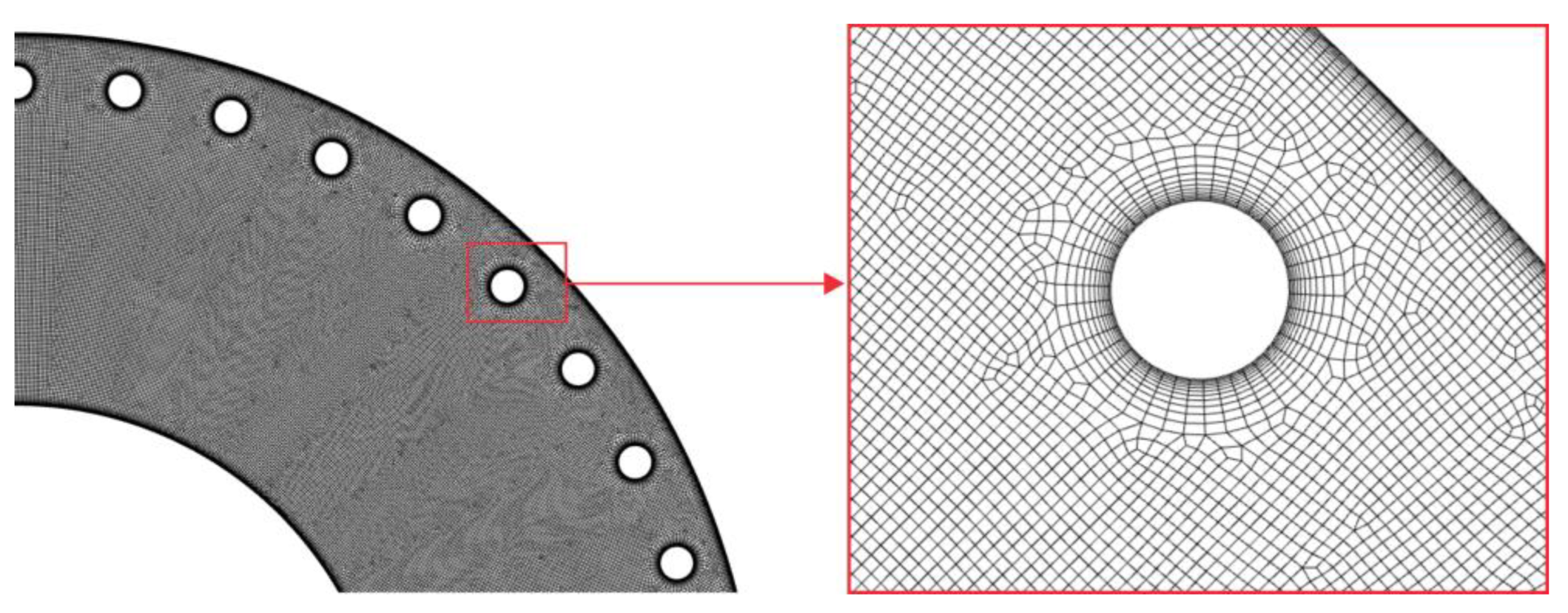
3.2. Grid Independency Test

To generate a computational mesh, the ANSYS meshing 19.2 software was used. A meshing strategy was based on a ratio of the radial cylinder’s radius to its near-wall cell’s height. The number of inflation layers near all walls in the radial direction was 12, with an expansion factor of 1.22. The default size of other cells was equaled to the height of the last inflation layer. In Table 1 six mesh configurations with varied cell heights are provided. To get an optimal grid distribution for a minimal computing time and a reasonable computational accuracy, several tests with Ra = 106, Ri = [10−2, 104] and Rr = 2.0 were conducted. The meshing relative error was calculated as follows:
N u i , c , o f N u i , c , o N u i , c , o × 100 % ,
where N u i , c , o f is the Nusselt number obtained in the test with the finest mesh. Results of the tests are provided in Table 2. Although Mesh#4 already had an acceptable error (no more 0.87%), for further calculations, Mesh#5 was chosen to increase the accuracy of calculations with Ri < 10−1. Here, the calculation time of one case was approximately 10 CPU hour, and up to 100 CPU hours for stable and unstable modes, respectively. The calculation time depended on the number of elements by a factor of approximately 1.5–2. Figure 2 shows the selected mesh geometry for the annulus with Rr = 2.0.

3.3. Validation of the Model

To verify the accuracy of the numerical solution, several tests for mixed convection inside the annular channel were performed. The most related studies of heat transfer in an annulus with a stationary and rotating cylinder were considered. For heat transfer between concentric cylinders, Raithby and Hollands [28,29] provided a correlation of heat flux per unit length of annular channel. Table 3 shows results of a comparative analysis between linear heat fluxes calculated with this correlation and the numerical model without radial cylinders. The comparison was carried out under the following conditions: Re = 0 (Ri = () and Pr = 0.7. For the steady inner cylinder, the numerical simulation results had good agreement with the average error of no more than 5%. To verify the reliability of the model to simulate heat transfer with the rotating cylinder, several tests with Pr = 1.0, Ra = 104, 105 and Rr = 2.6 were carried out and Lee’s data [14,15] compared. In this case, the Nusselt number was adapted similar to his and other authors studies [1,2] as follows:
N u i = R i ln ( R r ) S i T p 0 T p S i Θ d s d T .
As can be seen from Figure 3, the curves have the identical tendency and good agreement, the average deviation between simulations is no more than 4.5%. This means that the current model and computational approach have sufficient precision and accuracy for further investigation.

4. Results and Discussion

4.1. The Aim and Constraints of the Parametric Research

A wide range of parametric conditions has been explored to study heat transfer in the annular channel with the inner rotating cylinder in the presence of the radial cylinder array. The working fluid was air with the Prandtl number of 0.7. The present study is concerned with mixed convection. The Rayleigh number and the Richardson number are two dimensionless parameters used to evaluate the relative importance of the natural or forced convection. To account for all possible regimes of convection, Ri was varied from 10−2 to 104, and for the motionless inner cylinder, Ri = ∞ (a total of 12 values). The values of Ra were 104, 105, and 106. The direction of rotation of the inner cylinder was always counterclockwise (Figure 1). Radius ratios Rr were 1.4, 2.0, and 2.6. The dimensionless radius of radial cylinders was fixed Rc = 0.022(2)Ro, and the distance from their centers to the origin was Rcc = Ro − 3Rc = 0.934Ro. Three radial spacings were analyzed, namely a uniform distribution of 23, 30, and 40 cylinders that is equal to the dimensionless distance between their centers of Pc = 11Rc, Pc = 8.8Rc and Pc = 6.6Rc, respectively. In addition, for comparative analysis, the simulations without radial cylinders with all Ri, Ra, and Rr combinations were also conducted. Thus, the total number of cases in the full factor experiment was 432. Influences of every parameter on heat transfer in the following chapters are analyzed with isotherms, streamlines, and Nusselt number curves.

4.2. Influences of the Rayleigh and the Richardson Numbers

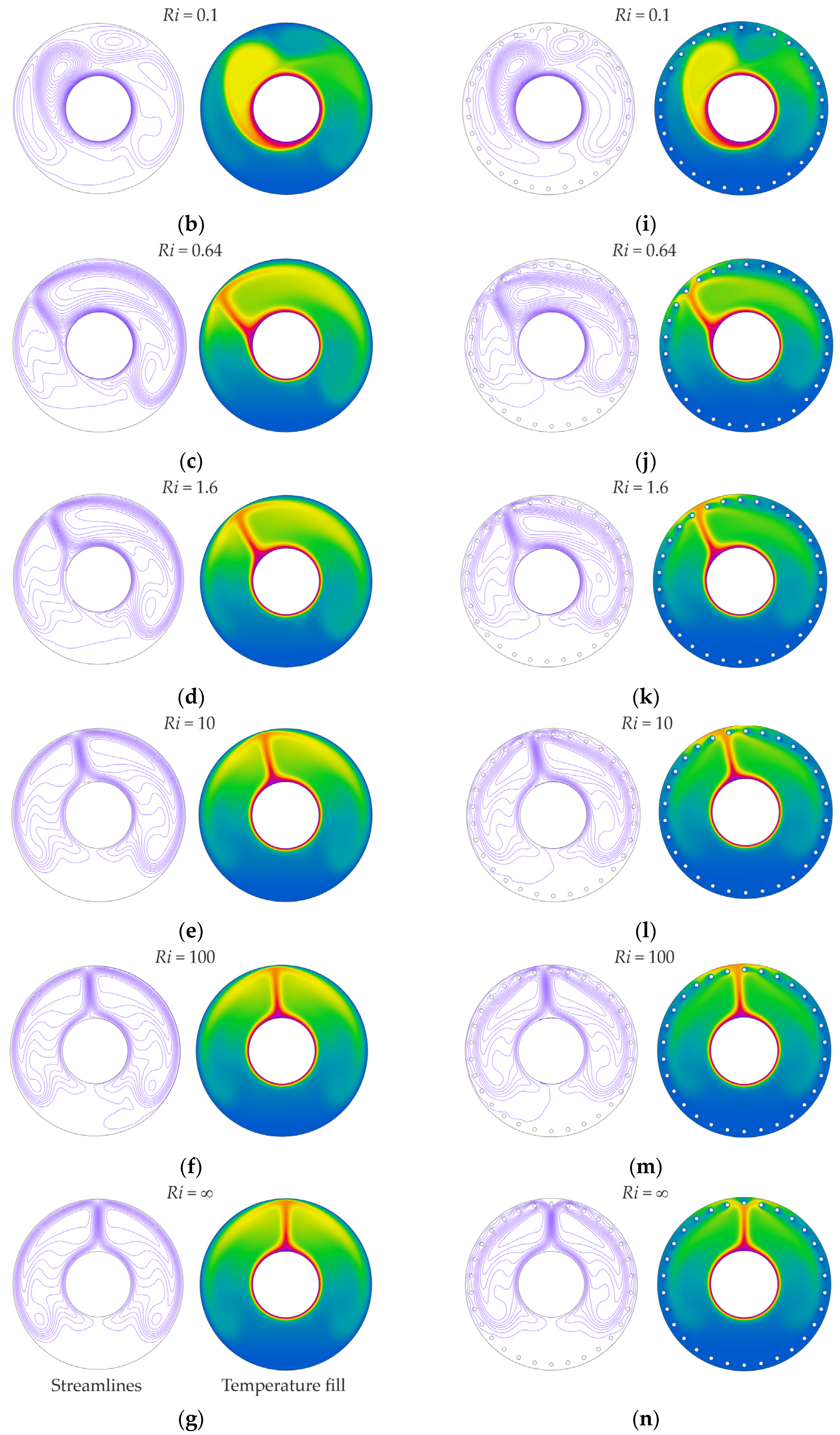
The effect of rotating the inner cylinder on the flow and temperature fields for different Ri is investigated first. The steady state (time-averaged) streamlines and temperature fills for different Ri, when Ra = 106, Rr = 2.6, and Pc = 8.8Rc, are depicted in Figure 4. To compare, on the left side of the figure, a state without radial cylinders was also added. When the Richardson number tends to minimum (Ri = 0.01) i.e., at the high angular velocity of the inner cylinder, there is an annular uniform forced counterclockwise flow, as shown in similar studies [2,16]. When Ri increases to 0.1, the mixed convection begins. This is because the angular velocity is no longer sufficient to maintain the annular flow. Consequently, several vortices warped in rotation direction formed in the top-left area of the enclosure. When the value Ri exceeds 10, natural convection prevails, and a formation of two symmetrical vortexes on both inner cylinder’s sides begins. At this point, the rotation has almost no effect on the flow. Such flow patterns in empty annuli were shown also in the study [2]. The increased free space around the rotating cylinder is characterized by the appearance of a plume of hotter fluid on top of the cylinder and by a displacement of the plume in the direction of rotation [3]. Radial cylinders somewhat change the nature of the flow. The differences are more noticeable only when Ri is greater than 0.1. A narrower plume penetrates between the upper cylinders, and it is more noticeably divided (more suppressed). The return flow from the plume along the outer wall and around the radial cylinders generates vortex fluxes around them. The radial cylinders reduce global vortices and generate small ones around them (Figure 4i–n, streamlines). The bulk temperature in the upper area of the annulus and around the radial cylinders decreases and becomes more uniform, which indicates an increase in heat transfer intensity.
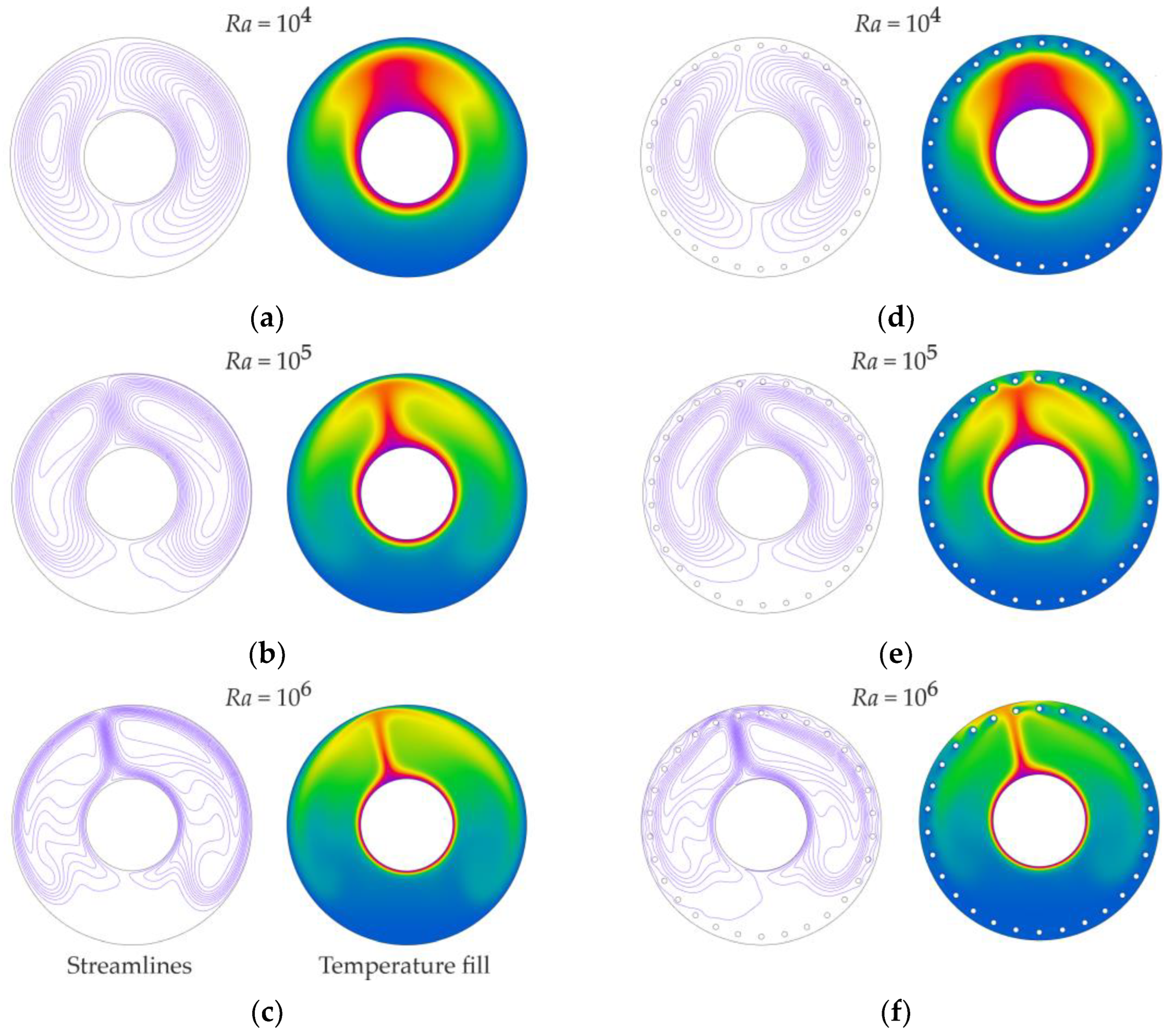
The Richardson number characterizes only the ratio of inertial forces and lift, which is not enough to unambiguously determine the flow regime. To do this, it is also necessary to take into account the relationship between friction forces (viscosity) and lift, for example, in the form of the Rayleigh number. The steady state (time-averaged) streamlines and temperature fills with Rr = 2.6, Pc = 8.8Rc for different Ra and Ri are depicted in Figure 5 and Figure 6. On the left side of the figures, a state with the empty annulus was also added. With Ra = 106, there is the distinct plume rotated in the direction of the inner cylinder rotation (with larger Ri by a minor rotation angle (Figure 6)). There is also a stable two-vortex structure of the flow. With Ra = 105, the patterns correlate with data [15]. When Ra decreases, the frictional forces dominate, and the plume expands (“washes out”) over the cylinder in the opposite to its rotation direction (clockwise). Similar behavior is compatible with the study [16] for Ra = 104 and Rr = 2. Thus, forced convection begins to prevail. The presence of radial cylinders does not make significant changes in the overall flow pattern at wider gaps. At the same time, they limit the size of global vortices, which leads to the decrease and homogenization of temperature in the area around radial cylinders and near the outer channel wall.
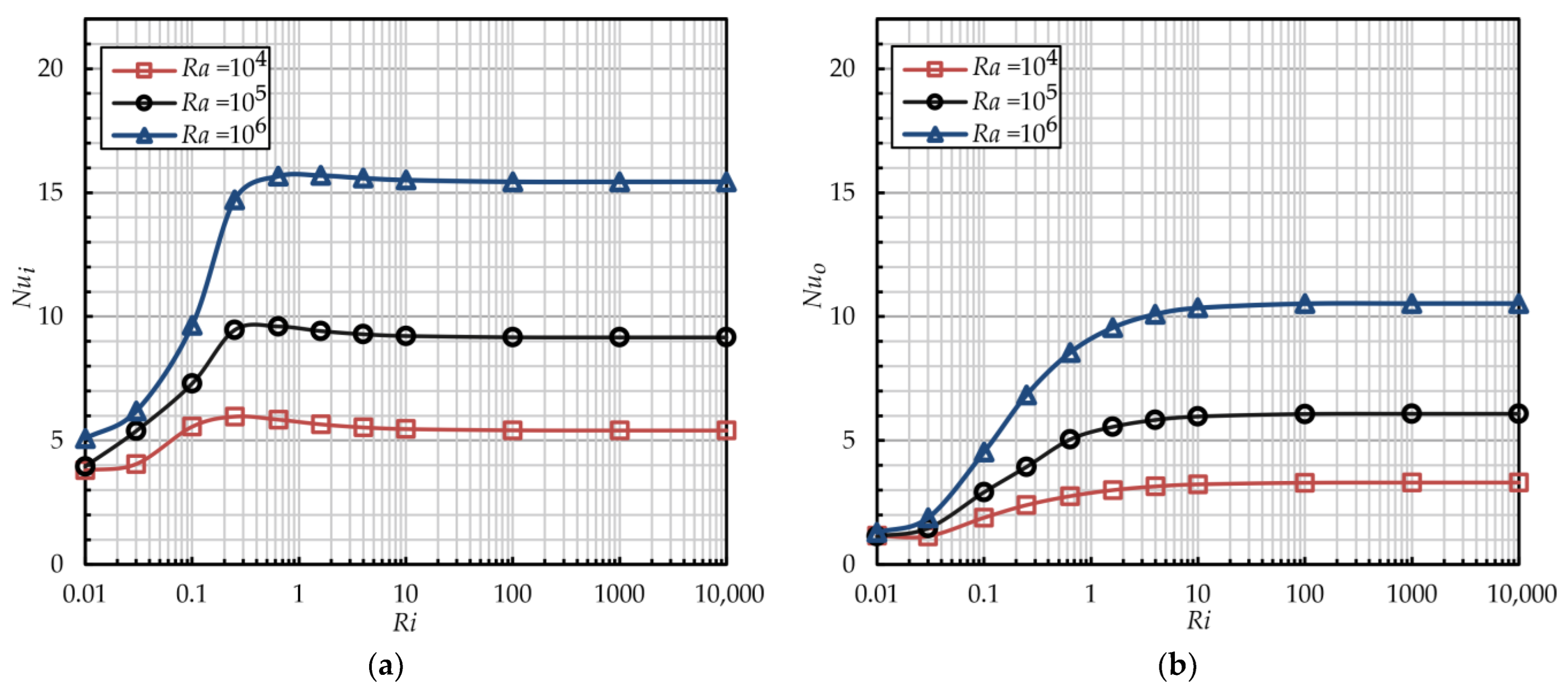
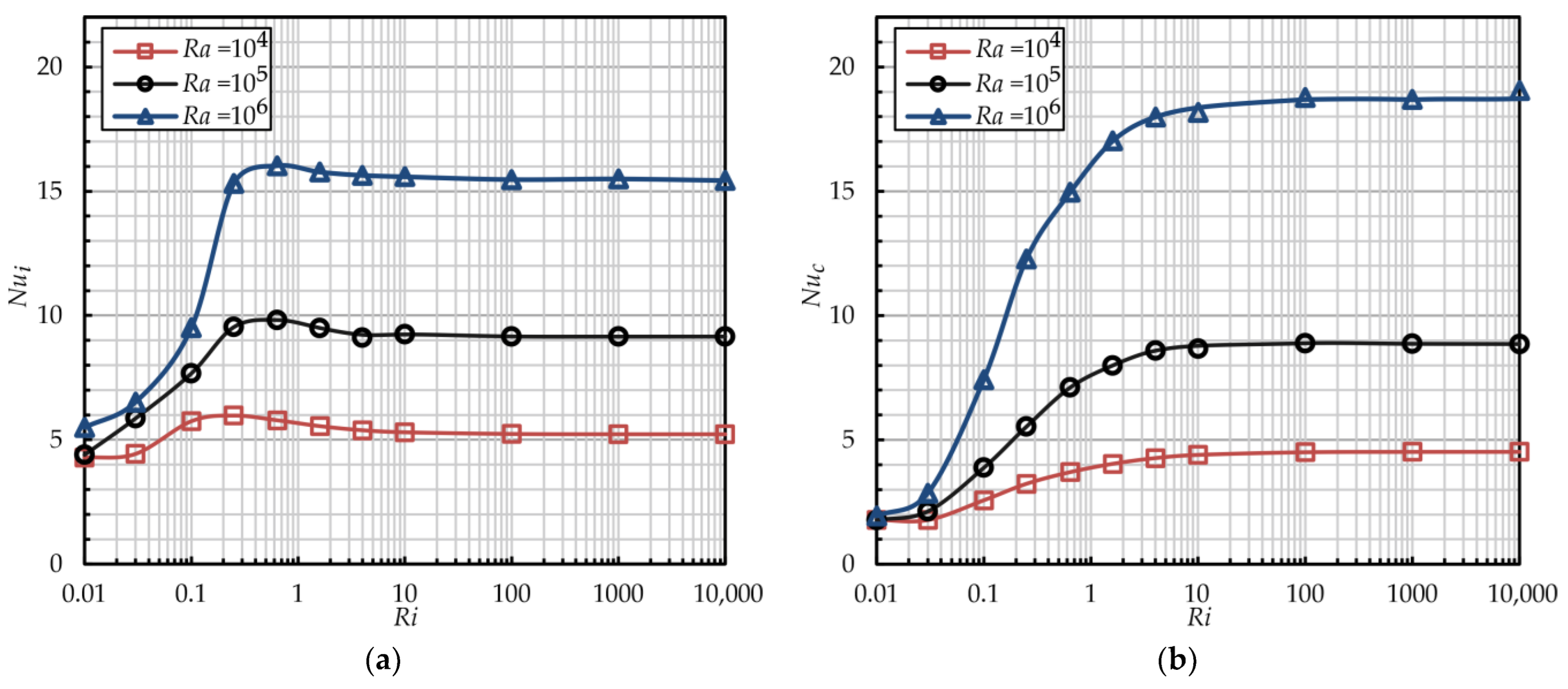
Figure 7 shows the dependencies of the Nusselt numbers on the Richardson number with Rr = 2.6 and the various Rayleigh numbers without radial cylinders. There are two main critical Richardson numbers (Rimin, Rimax). Below Rimin, the forced convection prevails (see flow pattern on Figure 4a), and heat is transferred almost with thermal conduction, because the radial mixing is minimal. Above Rimax, free convection prevails (Figure 4e–g), and a forced movement of air by the inner cylinder does not influence convection. For the inner cylinder, the dependence of the minimal critical Richardson number on the Rayleigh number is more noticeable: as Ra increases, Rimin reduces from 0.03 below 0.01. For the outer wall, Rimin is constant and equal to 0.01 for all Ra. In the mode below Rimin, the Nusselt numbers are the same and unaffected by Ra. In mixed convection mode, the influence of Ri on heat transfer for the inner cylinder and the outer wall is different. Although for both walls Rimax = 10, for the outer wall, the Nusselt number smoothly decreases with a decreasing of Ri below Rimax. For the inner cylinder, first, a minor increase of Nui on 1–2 is seen, although it falls abruptly to Rimin (Figure 7a). The Ri for this inflection point increases from 0.1 to 0.6 with the increase of Ra from 104 to 106, respectively. The shift of Rimin and the inflection point to smaller values with increasing Ra is associated with the growth of the lifting force, for the balance of which a higher rotation speed of the cylinder (lower Ri) is required. This is more noticeable for the inner cylinder, since, due to the low Pr and sheer stresses, disturbances from the moving wall of the inner cylinder do not reach the outer surface, and a more active interaction of forced and free convections occurs approximately in the region of its near-wall layer. It is similar to the study [25] with a square enclosure. In the inflection point, a formation of the two-vortex structure and the narrow plume is ended (Figure 4c). In free convection mode, Nusselt numbers are defined only by the Rayleigh number. When Ra increases from 104 to 106, the values of Nusselt numbers are increased from 5 to 15 for the inner wall, and from 3 to 10 for the outer wall. During the transition from the forced to the free convection mode, the increment in the Nusselt number increases also with the increase of Ra. For example, when Ra changes from 104 to 106, the Nusselt number increases 1.4 and 4 times, and 3 and 10 times on the inner and outer walls, respectively. Moreover, the heat transfer intensity on the outer wall of the empty annulus is 1.5 times lower than that of the inner cylinder.
Figure 8 shows the dependencies of the Nusselt numbers on the Richardson number with Rr = 2.6 and the various Rayleigh numbers with radial cylinders (Pc = 8.8Rc). The addition of cylinders in the channel does not lead to significant changes in the critical Ri or to a change in the intensity of heat transfer on the inner rotating cylinder. However, an exchange of the outer flat surface to the radial cylinder array increases the Nusselt number. In the free convection regime, Nuc increases 1.4 times (from 3.1 to 4.5) and 1.8 times (from 10.5 to 19) with Ra = 104 and Ra = 106, respectively. And even in the forced convection regime, Nuc increases 2 times (from 1 to 2). At the same time, the heat transfer intensity on the outer and inner surfaces is getting closer, and with Ra = 106 Nuc is higher just by 20% than on the inner cylinder. Nuc is higher because the cylinders act as an obstacle to the flow. They create additional mixing by increasing the vortex flow around them, compared to the more stagnant flow at the flat outer surface without radial cylinders (for example, the flows in Figure 4e,l can be compared). At the same time, heat transfer on the inner rotating cylinder remains relatively unchanged. This is especially true when the radius ratios are large, as the radial cylinders have a minimal impact on the flow structure near the inner cylinder.
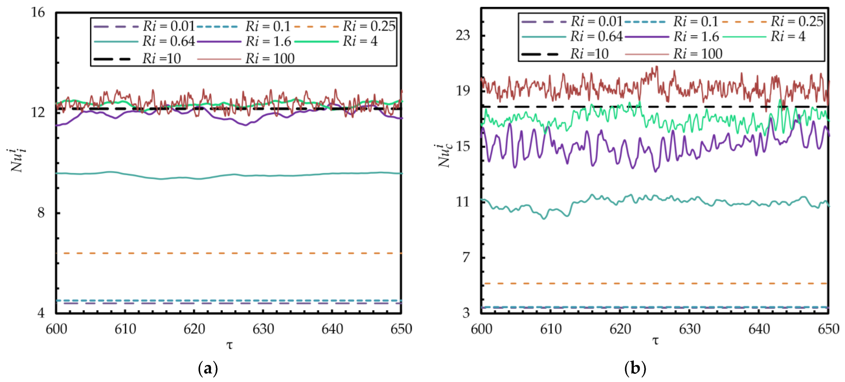
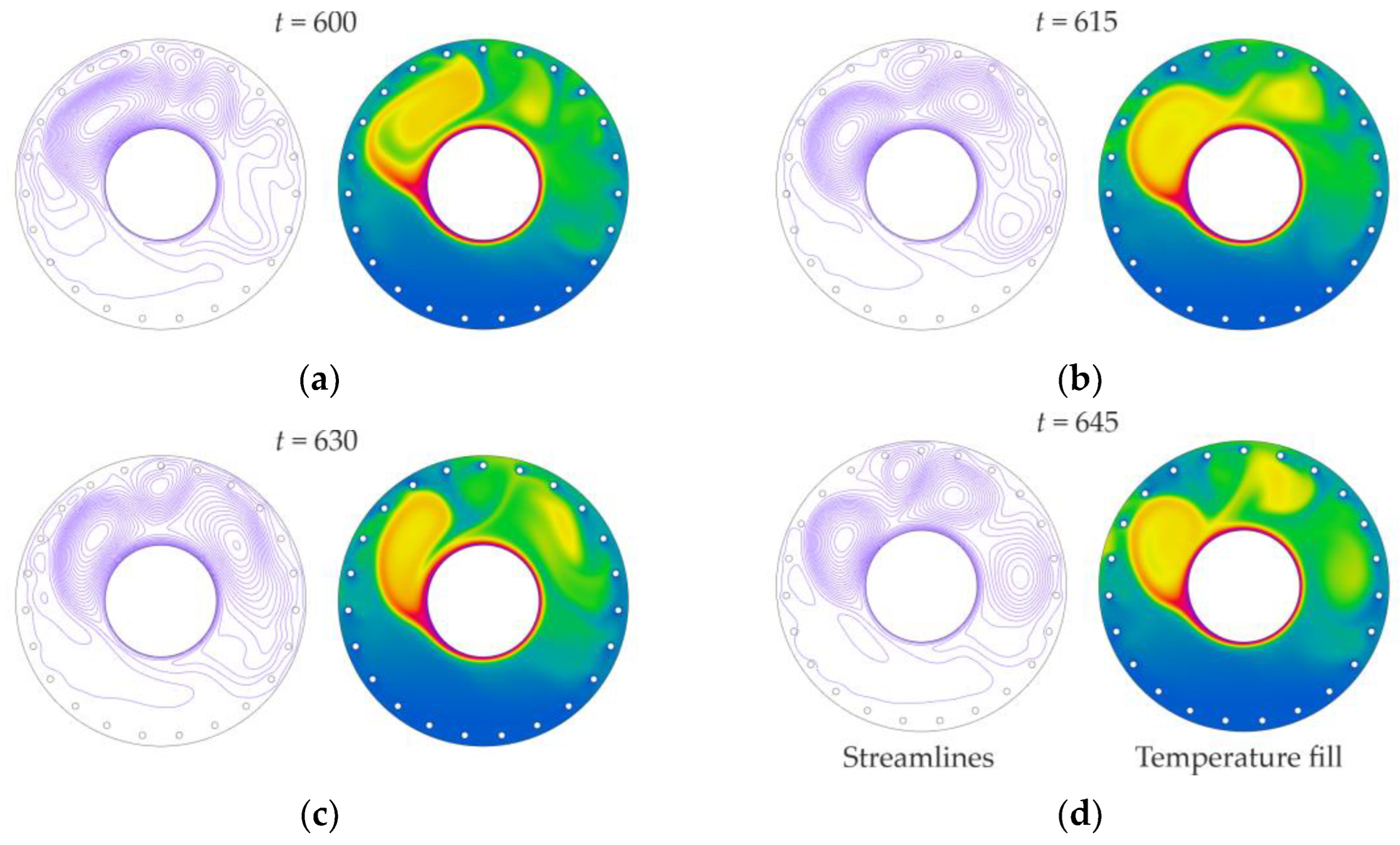
As noted in the study [25], depending on the regime and geometric parameters, when Ri increases, the flow in an enclosure can alternate between a more stable (“steady”) or a strongly destabilized (“unsteady”) one. Figure 9 shows a time dependence of instantaneous values of surface-average Nusselt numbers with different Richardson numbers and the radius ratio Rr = 1.4. It is shown that with Ri from 0.64 to 4 and more than 100, the values of the Nusselt number oscillate, and with other Ri the steady mode takes place. This fact can be explained by the vortex shedding that occurs in the channel, which is seen on several instantaneous flow patterns provided in Figure 10 (also see Figures S1–S4 of streamlines and temperature fills of the annulus for Ra = 106 in the Supplementary Materials). In this case, the radial cylinders act as an additional disturbance which prevents the oscillations from damping. When the radius ratio is 2.6 (Figure 11), unsteady modes with a lower frequency occur only at the beginning of the mixed convection mode with Ri from 0.1 to 0.25. This can be explained by the appearance in wider gaps of larger vortices, which fade with an increase in the Richardson number more quickly (Figure 12) (also see Figures S5 and S6 of streamlines and temperature fills of the annulus for Ra = 106 in the Supplementary Materials). In Choi and Kimt study [28] for Rr = 2.6, the destabilization effect was observed with Ri < 0.31. In most cases, the intensity of oscillations on the outer wall is higher than on the inner cylinder. The probability of the occurrence of unsteady modes increases with an increase in Ra above 104. A more detailed investigation of non-stationary effects necessitates a separate study, such as one similar to [30].

4.3. Influence of Radius Ratio Rr

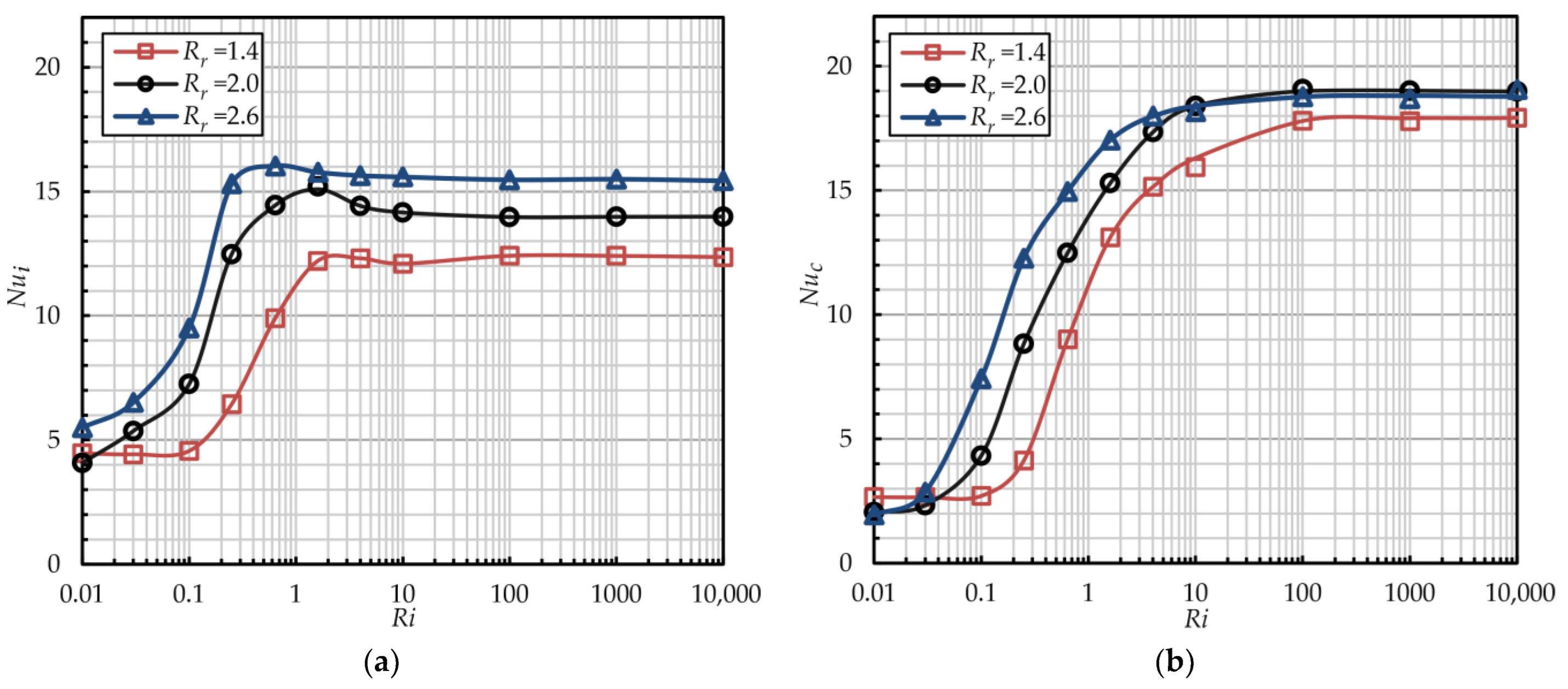
The steady state (time-averaged) streamlines and temperature fills for Ri = 1.6, Ra = 106 with radial cylinders (Pc = 8.8Rc) and different radius ratios are depicted in Figure 13. In narrow gaps, the flow is less stable, as larger vortices break down into smaller ones, leading to wave-like flows (see Figure 13a). The instability is further increased by the vortices generated behind the radial cylinders. For Rr > 2.0, the flow stabilizes in the form of two large symmetrical vortices. For the same conditions, Figure 14 shows the dependencies of the Nusselt number on the Richardson number with different radius ratios. For the inner cylinder, the critical value of Rimax is 10 for all ratios Rr. The values of Rimin decrease from 0.1 to below 0.01. Meanwhile, the values of Ri at the inflection point decrease from 1.6 to 0.25 as the ratio Rr increases from 1.4 to 2.6. Thus, the mixed convection zone expands as the ratio Rr increases. For the inner cylinder, Nui increases with the ratio Rr for all Ri. As the gap increases, the intensity of natural convection increases (the Rayleigh number grows faster than the Reynolds number), and the two-vortex global structure is forming. In the right area (Figure 13b,c), the reverse flow of a vortex, coinciding with the direction of the cylinder’s movement, increases the air velocity around the inner cylinder. The reverse flow of the vortex in the left area, moving in the opposite direction, increases the shear mixing of the boundary layer around the inner cylinder. This leads to an increase in the intensity of heat transfer with an increase in the ratio Rr. Increased vortex formation causes a slight increase in heat transfer intensity at the inflection point, as illustrated in Figure 13a,b.
For radial cylinders, the values of Rimin remain constant, while the values of Rimax increase to 100 for Rr < 2.0. Therefore, in narrow gaps with obstacles such as rows of cylinders, the mixed convection range widens significantly (see Figure 14a). In both mixed and free convection modes, the heat transfer intensity of radial cylinders increases with the radius ratio Rr. However, for Rr > 2.0, further increases in the gap do not significantly affect Nuc, regardless of the Ri values. At the same time, in the forced convection mode, the Nusselt number is higher for Rr = 1.4 compared to wider gaps. As the system transitions from forced to free convection mode, the increment in Nuc also rises with an increase in the radius ratio Rr. For example, when Rr changes from 1.4 to 2.6, Nuc increases 2.6 and 2.8 times and 6.8 and 9.5 times on the inner cylinder and on radial cylinders, respectively. In all gap configurations, the heat transfer intensity on the radial cylinders is greater than that on the inner cylinder. As the radius ratio increases, the ratio of Nuc to Nui decreases from 1.4 to 1.2.
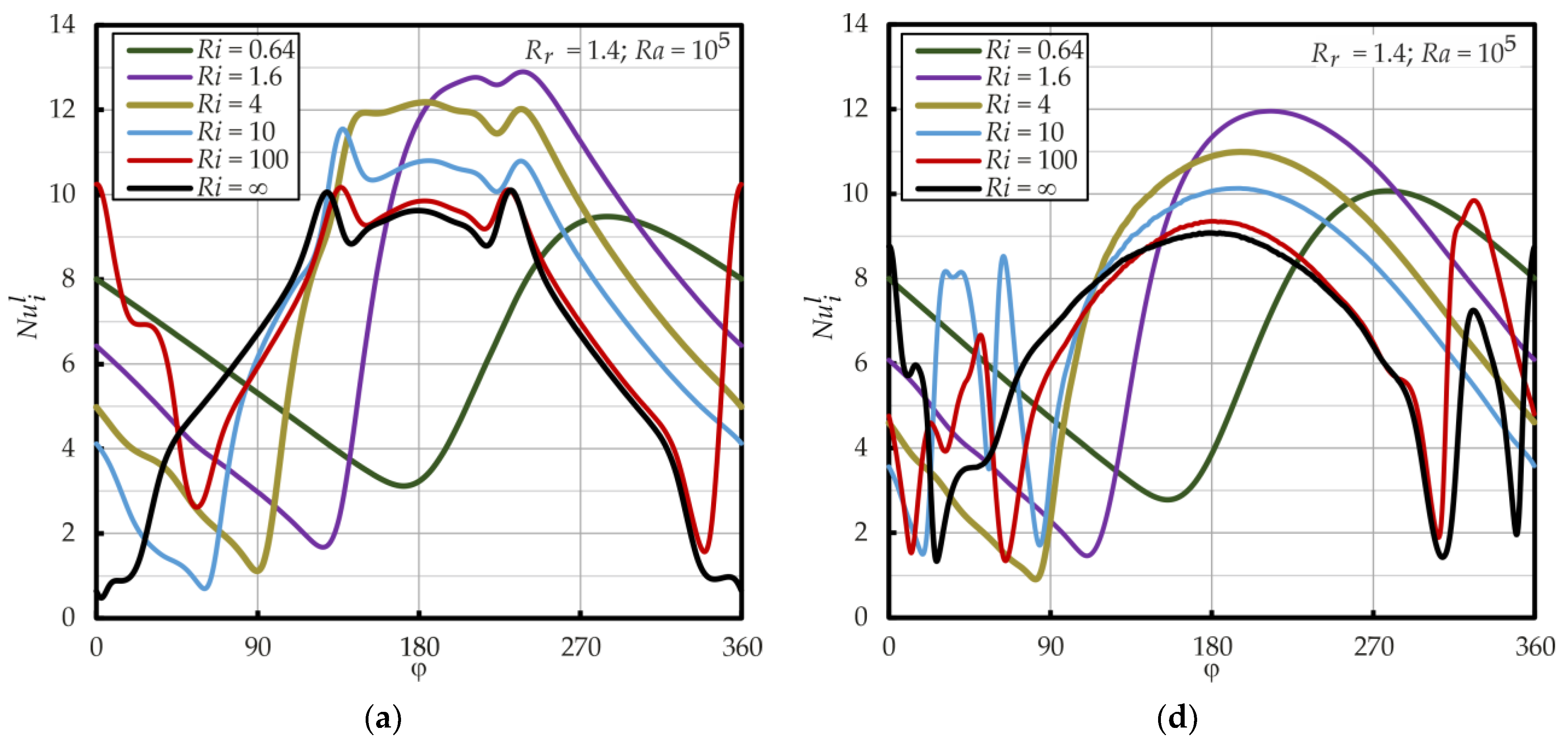
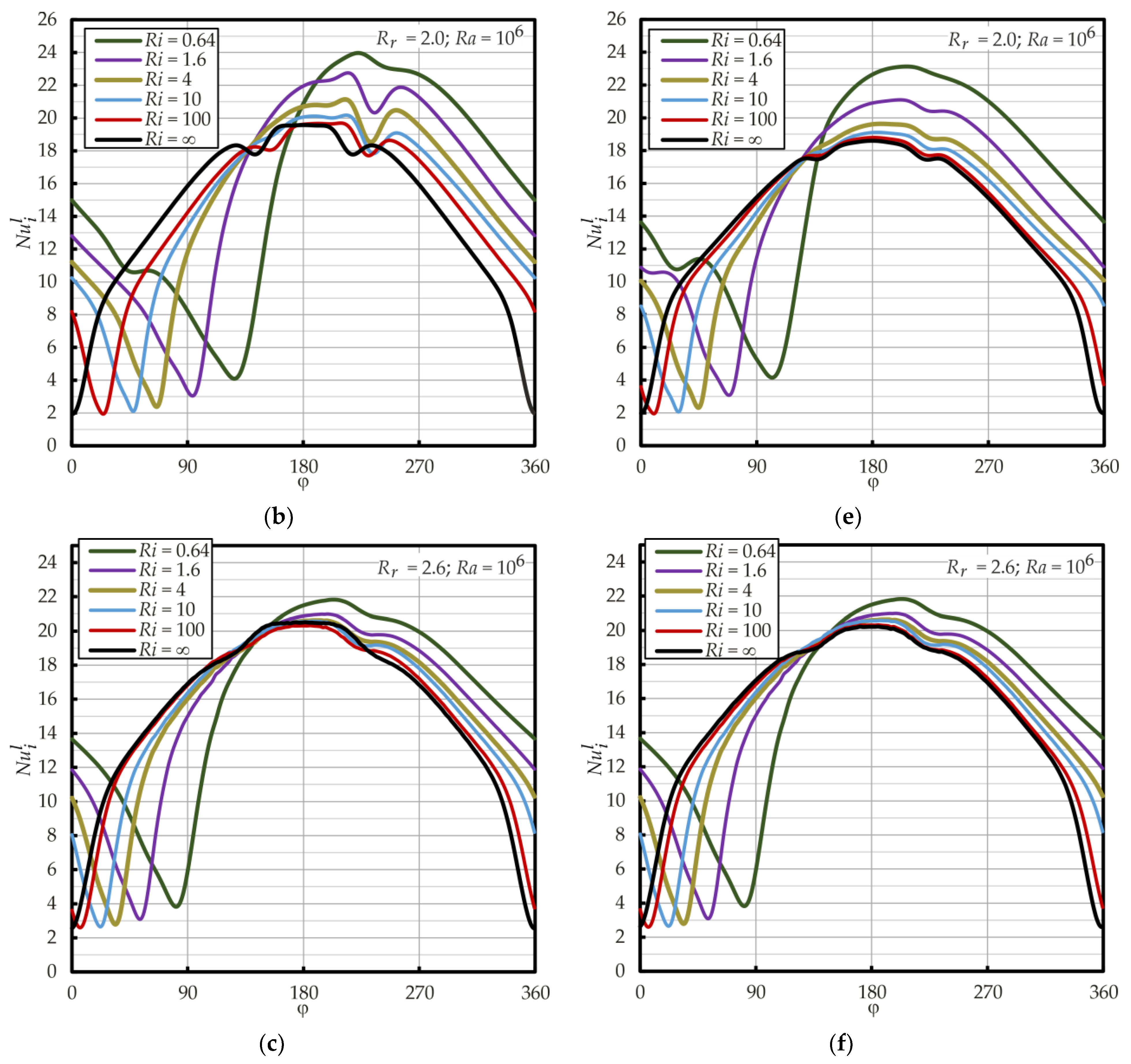
For a local heat transfer analysis, a distribution of the Nusselt number on the inner cylinder surface for different values of Ra and radius ratio Rr is provided in Figure 15. In all cases for the motionless cylinder, a local symmetrical maximum on the Nusselt number is observed at an angle of 180 degrees and a local minimum at 0 degrees. With a decrease in the Ri number (the increase in the rotation velocity), the values of maximum and minimum shift (‘turn’) in the direction of rotation. For annuli with smaller gaps and lower Ra values, this ‘turn’ occurs more rapidly and noticeably. For instance, at Ri = 1.6 and Rr = 1.4, the shift can reach up to 50 degrees, while for Rr = 2.6, it is only approximately 10 degrees. Thus, with an increase in the radius ratio, the shift of the local distribution tends toward the minimal angle. This is because with the Rr grow, the natural convection prevails and the influence of rotational effects on the local distribution decreases. With the decrease in Ri from Rimax to the inflection point, an increase in the local maximum and minimum values of the Nusselt numbers occurs, which leads to a slight increase in the surface-averaged Nusselt number (Figure 14a). With a further decrease in Ri, the abrupt drop in the maximum value of Nuil occurs, and the distribution begins to “compress” and tends to be linear (Figure 15a Ri = 0.64). Similar curves were obtained by Lee [13] for Rr = 2.6, Ra = 105, and Ri = [30, 0.3]. Radial cylinders cause a more pronounced change in the local distribution of heat transfer intensity in annuli with Rr < 2.0, especially with Ri > 4 (Figure 15d). Under these conditions, the distribution is less uniform compared to the empty annulus, as several segments with local maxima and minima of the Nusselt number emerge.

4.4. Effect of the Radial Cylinder Spacing

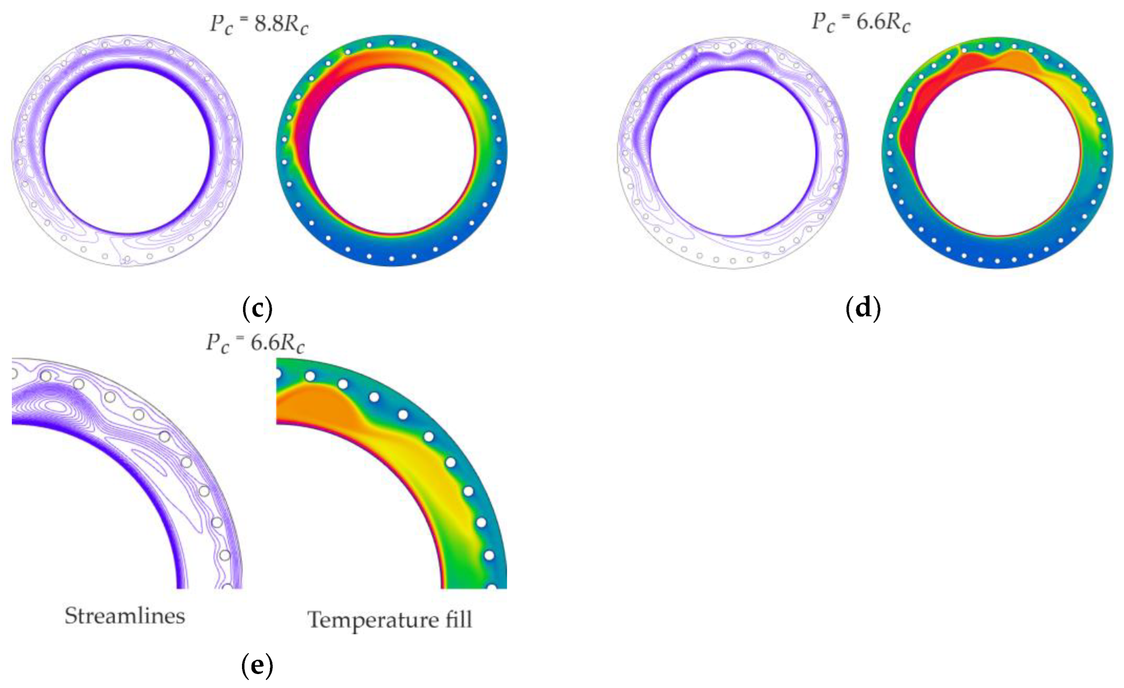
The steady state (time-averaged) streamlines and temperature fills for Ri = 1.6, Ra = 105 with the radius ration Rr = 2.6 and different pitches are depicted in Figure 16. Introducing radial cylinders creates flow disturbances along the outer flat surface of the annulus. The increased heat transfer intensity on the radial cylinders results in the formation of a low-temperature area around them and along the outer wall of the channel. As the number of cylinders increases (the pitch decreases), it becomes more difficult for the lifting plume of hotter air to penetrate through their row. As a result, with minimal cylinder spacing, warm air is “locked” in the upper part of the channel due to restricted circulation. For the same conditions, Figure 17 shows the dependencies of the Nusselt numbers on the Richardson number with different radial cylinder spacings (Pc). For the inner cylinder in wide gaps, for all values of Pc, the critical values of Rimin and Rimax are below 0.01 and 10, respectively. The inflection points are similar for all pitches, occurring at approximately Ri = 0.8. In general, heat transfer on the inner cylinder is independent of pitches Pc, and during the transition from the forced to the free convection mode, Nui increases from approximately 4 to 9. For radial cylinders, the pitches do not influence the values of Rimin and Rimax, which are approximately 0.03 and 10, respectively. At the same time, the pitch of cylinders significantly influences the heat transfer’s intensity. In wide gaps, the maximum values of Nuc (approximately 12) occur at the maximum pitch (Pc = 11Rc). As Pc decreases, the heat transfer intensity drops to levels similar to those in annuli without radial cylinders (approximately half). The decrease in heat transfer intensity in cylinder rows with decreasing pitch was also demonstrated in the studies of Kitamura et al. [19,20]. This is due to the fact that, when the cylinders approach each other, they enter each other’s stagnant zones, which suppresses convective heat transfer (Figure 16e). The ratio of inner and outer surface Nusselt numbers also depends on pitch: as Pc decreases from 11Rc to 6.6Rc, this ratio decreases from approximately 1.2 to 0.7.
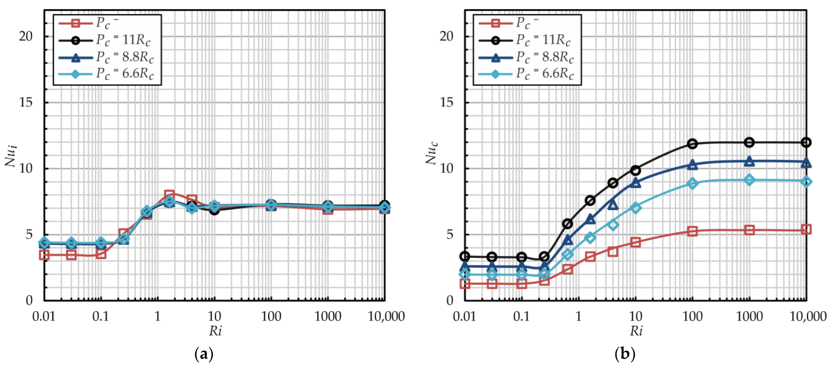
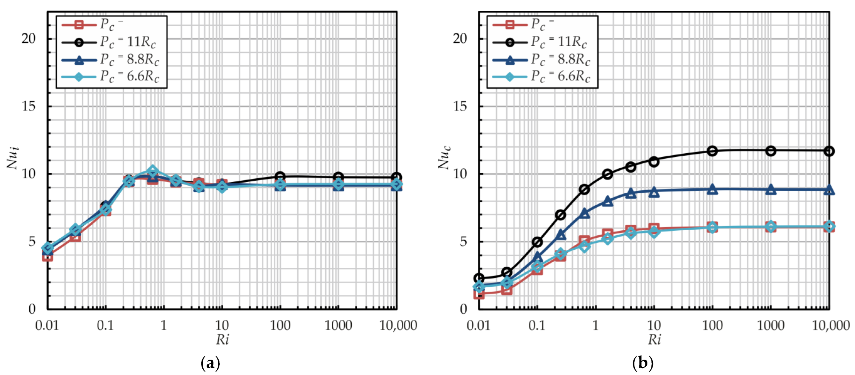
The pitches of radial cylinders have a more significant influence on flow and heat transfer in annular channels with smaller radius ratios. The steady state (time-averaged) streamlines and temperature fills for Ri = 1.6, Ra = 105, Rr = 1.4 and different pitches are depicted in Figure 18. Because the radial cylinders in the narrow channel are positioned closer to the inner cylinder, they introduce flow disturbances throughout the entire flow, which increases resistance to air movement. In contrast to annuli with wide gaps, the wave-like flow in the narrow gaps impacts both the inner cylinder and the radial cylinders. Moreover, when the cylinder pitches decrease, the wave flow is “pressed” against the inner cylinder. For the same conditions, Figure 19 shows the dependencies of the Nusselt numbers on the Richardson number with different radial cylinder spacings (Pc). In narrow gaps, as in wide gaps, the critical values of Rimin, Rimax, and the inflection points are consistent across all pitches Pc for both the inner and radial cylinders. The intensity of heat transfer on the inner cylinder is also independent of pitches Pc, and during the transition from the forced to the free convection mode, Nui increases from approximately 4 to 7. At the same time, the heat transfer intensity on radial cylinders depends significantly on their pitch. The maximal values of Nuc (approximately 12) are observed with the maximal pitch (Pc = 11Rc). As Pc decreases, the heat transfer intensity drops to 9 (a reduction of 1.3 times). However, in narrow gaps, Nuc is approximately 1.8 times higher than in annuli without radial cylinders. The smaller drop in heat transfer intensity in radial cylinders with decreasing pitch is associated with increased transverse oscillations between the cylinders, which are generated by the wave flow around the inner rotating cylinder (Figure 18e). The ratio of inner and outer surface Nusselt numbers also depends on pitch: when Pc decreases from 11Rc to 6.6Rc, this ratio decreases approximately from 1.7 to 1.3, respectively.
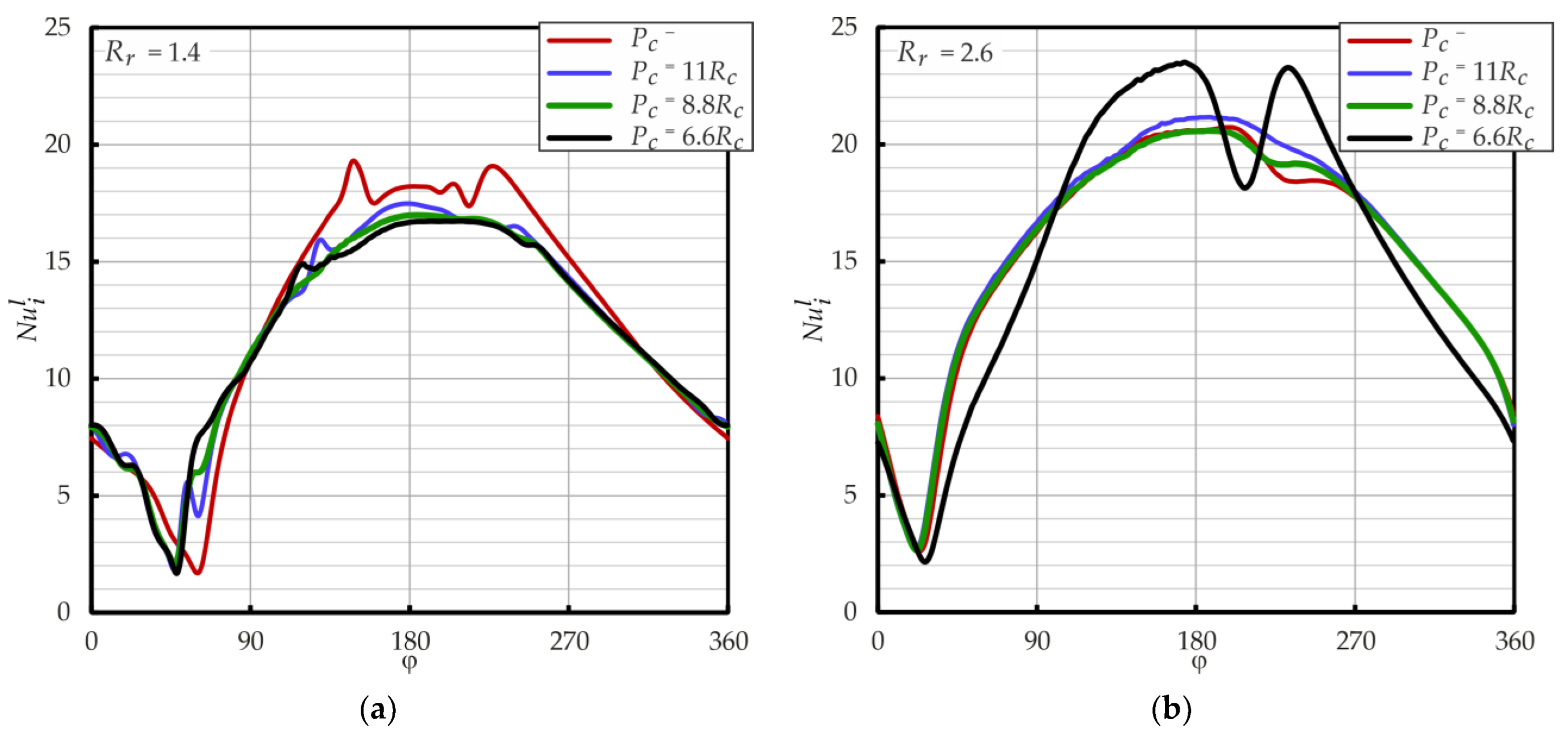
To estimate the influence of the radial cylinder spacing on the distribution of the local heat transfer intensity on the inner cylinder surface, the Nusselt numbers’ curves for different values of radius ratio are provided in Figure 20. As can be seen, for the radius ratio of 1.4, the distribution of Nuil along the circumference of the inner cylinder has a smooth profile with a symmetrical maximum at approximately 180 degrees and a minimum (sharp reverse peak) at 0 to 90 degrees, depending on Ri. It can be noted that, in annular channels with radial cylinders, compared to the empty annulus, the maximum values of the Nusselt number are slightly reduced, and the distribution becomes more uniform. At the same time, a change in the pitches does not lead to significant changes in the local distribution of Nuil. For annuli with wide gaps, in general, the profile of Nuil remains the same. Only when the pitch is reduced from 8.8Rc to 6.6Rc does a noticeable change in the distribution curve occur. On angles from 180 to 250 degrees, Nuil increases with the appearance of two local maxima. Increasing the pitch by more than 8.8Rc does not lead to noticeable changes in the profile.

5. Conclusions

Numerical investigations of heat transfer, from forced to free convection regimes, within the annular channel with and without radial cylinders with a rotating inner cylinder, using the finite-volume method, are carried out for the first time. The heat transfer quantities are obtained for different Rayleigh numbers (104–106), radius ratios (1.4–2.6), radial cylinder spacing (11Rc–6.6Rc), and rotating velocities in the form of the Richardson number (10−2–104). Based on the results, the following main conclusions can be summarized:
  • The addition of radial cylinders does not result in significant changes in the critical Ri, nor does it alter the intensity or local distribution of the heat transfer on the inner rotating cylinder. The Nusselt number increases when the outer flat surface is replaced by the radial cylinder array: in the free convection regime, 1.4 times and 1.8 times with Ra = 104 and Ra > 105, respectively, and in the forced convection regime, two times. In the forced regime, the intensity of heat transfer on the inner and radial cylinders varies only minimally. With Ra = 106, the Nusselt number for the radial cylinders is 20% higher than that of the inner cylinder.
  • For wide annuli gaps Rr > 2.0 with radial cylinders, the maximal values of the Nusselt number are observed with the maximal pitch (Pc = 11Rc), and with the minimal pitch (Pc = 3.3Rc), the heat transfer intensity falls to the same level as for annuli without radial cylinders (approximately 2 times lower). In narrow gaps Rr < 2.0, the maximal Nusselt number is also observed with the maximal pitch; however, with the minimal pitch, the heat transfer intensity is still approximately 1.8 times higher than for the flat outer wall.
Investigations of the influence of other parameters of the radial cylinder arrangement on heat transfer (a distance to the outer wall, a relative position, a radius of cylinders, etc.) should be continued. Also, a more detailed study of non-stationary effects requires additional studies.

Supplementary Materials

The following supporting information can be downloaded at: https://www.mdpi.com/article/10.3390/en17236047/s1, Figure S1: Streamlines and temperature fills of the annulus with Ri = 0.64, Ra = 106, Rr = 1.4, Pc = 11Rc. Figure S2: Streamlines and temperature fills of the annulus with Ri = 1.6, Ra = 106, Rr = 1.4, Pc = 11Rc. Figure S3: Streamlines and temperature fills of the annulus with Ri = 4, Ra = 106, Rr = 1.4, Pc = 11Rc. Figure S4: Streamlines and temperature fills of the annulus with Ri = 100, Ra = 106, Rr = 1.4, Pc = 11Rc. Figure S5: Streamlines and temperature fills of the annulus with Ri = 0.1, Ra = 106, Rr = 2.6, Pc = 11Rc. Figure S6: Streamlines and temperature fills of the annulus with Ri = 0.25, Ra = 106, Rr = 2.6, Pc = 11Rc.

Author Contributions

Conceptualization, A.S. and A.H. (Aigul Haibullina); methodology, D.B., I.G., T.I. and V.B.; software, A.H. (Aidar Hayrullin) and A.S.; validation, M.K. and A.H. (Aidar Hayrullin); investigation, A.H. (Aigul Haibullina) and M.K.; resources, D.B., I.G., T.I. and V.B.; formal analysis, A.H. (Aigul Haibullina), A.H. (Aidar Hayrullin), A.S. and M.K.; writing—original draft preparation, A.H. (Aidar Hayrullin) and A.S.; writing—review and editing, A.H. (Aidar Hayrullin), A.H. (Aigul Haibullina) and A.S.; visualization, A.H. (Aidar Hayrullin); supervision, A.H. (Aidar Hayrullin); project administration, A.H. (Aidar Hayrullin) All authors have read and agreed to the published version of the manuscript.

Funding

We would like to acknowledge financial supports for this work provided by the Russian Science Foundation, grant number 24-29-00461, https://rscf.ru/en/project/24-29-00461/, accessed on 29 November 2024.

Data Availability Statement

The data presented in this study are available on request from the corresponding author.

Conflicts of Interest

The authors declare no conflicts of interest.

Nomenclature

Nomenclature
Cpspecific heat, J∙(kgK)−1
ggravitational acceleration, 9.81 m∙s−2
GrGrashof number
L = ro − richaracteristic length (annuli gap width), m
ncnumber of radial cylinders
NuNusselt number
p, Ppressure, Pa, dimensionless pressure
pc, Pcradial spacing of radial cylinders (pitch), m, dimensionless spacing
PrPrandtl number
r, Rradius, m, dimensionless radius
RaRayleigh number
rcc, Rccdistance from radial cylinder centers to the annular channel center, m, dimensionless distance
ReReynolds number
RiRichardson number
Rrradius ratio
Sarea of surface, m2
t, Θtemperature, K, dimensionless temperature
T, τtime, s, dimensionless time
Tpaveraging period
u,v; U,Vvelocity components in x and y directions, m∙s−1; dimensionless velocity components
x, y; X,YCartesian coordinates, m; dimensionless coordinates
Greek symbols
βthermal expansion factor, K−1
φangle
λthermal conductivity, W∙(m∙K)−1
νkinematic viscosity, m2∙s−1
ρdensity, kg∙m−3
ωrotational rate, s−1
Subscripts
cradial cylinders
iinner cylinder
oouter wall
bbulk
Supersubscripts
ffinest mesh
iinstantaneous
llocal

References

  1. Yoo, J.-S. Mixed Convection of Air between Two Horizontal Concentric Cylinders with a Cooled Rotating Outer Cylinder. Int. J. Heat Mass Transf. 1998, 41, 293–302. [Google Scholar] [CrossRef]
  2. Chart, M. Numerical Prediction of Turbulent Mixed Convection in a Concentric Horizontal Rotating Annulus with Low-Re Two-Equation Models. Int. J. Heat Mass Transf. 1998, 41, 1633–1643. [Google Scholar] [CrossRef]
  3. Farouk, B.; Ball, K.S. Convective Flows around a Rotating Isothermal Cylinder. Int. J. Heat Mass Transf. 1985, 28, 1921–1935. [Google Scholar] [CrossRef]
  4. Ozerdem, B. Measurement of Convective Heat Transfer Coefficient for a Horizontal Cylinder Rotating in Quiescent Air. Int. Commun. Heat Mass Transf. 2000, 27, 389–395. [Google Scholar] [CrossRef]
  5. Ma, H.; Xia, W.; Zhou, W.; Liu, W.; Guo, Z.; Zhang, C.; Zhang, Y.; Deng, N. Experimental Investigation on the Steady, External Laminar Mixed Convection Heat Transfer Characteristics around a Large Diameter Horizontal Rotating Cylinder. Int. Commun. Heat Mass Transf. 2014, 57, 239–246. [Google Scholar] [CrossRef]
  6. Ma, H.; Lu, W.; Zhou, W.; Ding, Z.; Lü, X.; Cao, Y.; Zhang, Y.; Deng, N. Effects of Rotation on the Trailing Vortex and Heat Transfer from a Horizontal Rotating Cylinder at Higher Grashof Number. Int. Commun. Heat Mass Transf. 2015, 68, 20–26. [Google Scholar] [CrossRef]
  7. Ghaddar, N.K.; Thiele, F. Natural Convection over a Rotating Cylindrical Heat Source in a Rectangular Enclosure. Numer. Heat Transf. Part A Appl. 1994, 26, 701–719. [Google Scholar] [CrossRef]
  8. Costa, V.A.F.; Raimundo, A.M. Steady Mixed Convection in a Differentially Heated Square Enclosure with an Active Rotating Circular Cylinder. Int. J. Heat Mass Transf. 2010, 53, 1208–1219. [Google Scholar] [CrossRef]
  9. Hussain, S.H.; Hussein, A.K. Mixed Convection Heat Transfer in a Differentially Heated Square Enclosure with a Conductive Rotating Circular Cylinder at Different Vertical Locations. Int. Commun. Heat Mass Transf. 2011, 38, 263–274. [Google Scholar] [CrossRef]
  10. Khanafer, K.; Aithal, S.M. Mixed Convection Heat Transfer in a Lid-Driven Cavity with a Rotating Circular Cylinder. Int. Commun. Heat Mass Transf. 2017, 86, 131–142. [Google Scholar] [CrossRef]
  11. Alsabery, A.I.; Alshukri, M.J.; Jabbar, N.A.; Eidan, A.A.; Hashim, I. Entropy Generation and Mixed Convection of a Nanofluid in a 3D Wave Tank with Rotating Inner Cylinder. Energies 2022, 16, 244. [Google Scholar] [CrossRef]
  12. Hassen, W.; Selimefendigil, F.; Ben Khedher, N.; Kolsi, L.; Borjini, M.N.; Alresheedi, F. Control of Magnetohydrodynamic Mixed Convection and Entropy Generation in a Porous Cavity by Using Double Rotating Cylinders and Curved Partition. ACS Omega 2021, 6, 35607–35618. [Google Scholar] [CrossRef] [PubMed]
  13. Fénot, M.; Bertin, Y.; Dorignac, E.; Lalizel, G. A Review of Heat Transfer between Concentric Rotating Cylinders with or without Axial Flow. Int. J. Therm. Sci. 2011, 50, 1138–1155. [Google Scholar] [CrossRef]
  14. Lee, T.S. Laminar Fluid Convection between Concentric and Eccentric Heated Horizontal Rotating Cylinders for Low-Prandtl-Number Fluids. Int. J. Numer. Methods Fluids 1992, 4, 1037–1062. [Google Scholar] [CrossRef]
  15. Lee, T.S. Numerical Study of Mixed Heat and Fluid Flow in Annuli of Heated Rotating Cylinders. Int. J. Comput. Fluid Dyn. 1998, 9, 151–163. [Google Scholar] [CrossRef]
  16. Prud’homme, M.; Robillard, L.; Hilal, M. Natural Convection in an Annular Fluid Layer Rotating at Weak Angular Velocity. Int. J. Heat Mass Transf. 1993, 36, 1529–1539. [Google Scholar] [CrossRef]
  17. Schneider, M.; Younis, B.A.; Weigand, B. Large-Eddy Simulations of Flow and Heat Transfer in Heated Concentric Annulus with Inner Cylinder Rotation. Int. J. Heat Mass Transf. 2017, 114, 1248–1262. [Google Scholar] [CrossRef]
  18. Yang, H.Q.; Yang, K.T.; Lloyd, J.R. Natural Convection Suppression in Horizontal Annuli by Azimuthal Baffles. Int. J. Heat Mass Transf. 1988, 31, 2123–2135. [Google Scholar] [CrossRef]
  19. Kitamura, K.; Mitsuishi, A.; Suzuki, T. Natural Convection Heat Transfer from Horizontal Array of Heated Cylinders. Trans. JSME 2014, 80, TEP0201. (In Japanese) [Google Scholar] [CrossRef]
  20. Kitamura, K.; Mitsuishi, A.; Suzuki, T.; Kimura, F. Fluid Flow and Heat Transfer of Natural Convection Induced around a Vertical Row of Heated Horizontal Cylinders. Int. J. Heat Mass Transf. 2016, 92, 414–429. [Google Scholar] [CrossRef]
  21. Ashjaee, M.; Yousefi, T. Experimental Study of Free Convection Heat Transfer from Horizontal Isothermal Cylinders Arranged in Vertical and Inclined Arrays. Heat Transf. Eng. 2007, 28, 460–471. [Google Scholar] [CrossRef]
  22. Mun, G.S.; Park, Y.G.; Yoon, H.S.; Kim, M.; Yeong Ha, M. Natural Convection in a Cold Enclosure with Four Hot Inner Cylinders Based on Diamond Arrays (Part-I: Effect of Horizontal and Vertical Equal Distance of Inner Cylinders). Int. J. Heat Mass Transf. 2017, 111, 755–770. [Google Scholar] [CrossRef]
  23. Mun, G.S.; Seo, Y.M.; Park, Y.G.; Ha, M.Y. Natural Convection in a Cold Enclosure with Four Hot Inner Cylinders in a Diamond Array (Part-II: Effect of Unequal Horizontal and Vertical Distances of Inner Cylinders). Int. J. Heat Mass Transf. 2018, 120, 1365–1373. [Google Scholar] [CrossRef]
  24. Abd Al-Hasan, A.Q.; Ismael, M.A.; Ghalambaz, M. Heat Transfer in a Vessel-Tubes Array with a Rotating Baffle: A Rotating Frame Modeling Approach. Int. J. Thermofluids 2024, 22, 100659. [Google Scholar] [CrossRef]
  25. Liao, C.C.; Lin, C.A. Mixed Convection of a Heated Rotating Cylinder in a Square Enclosure. Int. J. Heat Mass Transf. 2014, 72, 9–22. [Google Scholar] [CrossRef]
  26. Patankar, S.V. Numerical Heat Transfer and Fluid Flow; Electro Skills Series; Hemisphere Publishing Corporation: London, UK, 1980; ISBN 978-0-07-048740-6. [Google Scholar]
  27. Yang, H.; Zhang, W.; Zhu, Z. Unsteady Mixed Convection in a Square Enclosure with an Inner Cylinder Rotating in a Bi-Directional and Time-Periodic Mode. Int. J. Heat Mass Transf. 2019, 136, 563–580. [Google Scholar] [CrossRef]
  28. Raithby, G.D.; Hollands, K.G.T. A General Method of Obtaining Approximate Solutions to Laminar and Turbulent Free Convection Problems. Adv. Heat Transf. 1975, 11, 265–315. [Google Scholar] [CrossRef]
  29. Kuehn, T.H.; Goldstein, R.J. An Experimental Study of Natural Convection Heat Transfer in Concentric and Eccentric Horizontal Cylindrical Annuli. J. Heat Transf. 1978, 100, 635–640. [Google Scholar] [CrossRef]
  30. Choi, J.Y.; Kimt, M.-U. Three-Dimensional Linear Stability of Mixed-Convective Flow between Rotating Horizontal Concentric Cylinders. Int. J. Heat Mass Transf. 1995, 38, 27–285. [Google Scholar] [CrossRef]
Figure 1. Schematic configuration of the model (the number of outer cylinders is shown conditionally).
Energies 17 06047 g001
Figure 2. The optimal mesh of the annular channel with Rr = 2.0.
Energies 17 06047 g002
Figure 3. The validation model results: 1—Ra = 104 [14,15]; 2—Ra = 105 [14,15]; 3—the present study for Ra = 104, 4—the present study for Ra = 105.
Energies 17 06047 g003
Figure 4. Streamlines (left) and temperature fills (right) of the annulus without (ag) and with radial cylinders (hn) with Ra = 106, Rr = 2.6, Pc = 8.8Rc, and different values of Ri.
Energies 17 06047 g004aEnergies 17 06047 g004b
Figure 5. Streamlines (left) and temperature fills (right) of the annulus without (ac) and with radial cylinders (df) with Ri = 0.64, Rr = 2.6, Pc = 8.8Rc, and different values of Ra.
Energies 17 06047 g005
Figure 6. Streamlines (left) and temperature fills (right) of the annulus without (ac) and with radial cylinders (df) with Ri = 10, Rr = 2.6, Pc = 8.8Rc and different values of Ra.
Energies 17 06047 g006
Figure 7. The Nusselt number vs. the Richardson number with Rr = 2.6 and different Rayleigh numbers without radial cylinders: (a) the inner cylinder; (b) the outer wall.
Energies 17 06047 g007
Figure 8. The Nusselt number vs. the Richardson number with Rr = 2.6 and different Rayleigh numbers with radial cylinders (Pc = 8.8Rc): (a) the inner cylinder; (b) radial cylinders.
Energies 17 06047 g008
Figure 9. Instantaneous Nusselt number vs. time with Ra = 106, Rr = 1.4, Pc = 11Rc for different Ri: (a) the inner cylinder; (b) radial cylinders.
Energies 17 06047 g009
Figure 10. Instantaneous streamlines (left) and temperature fills (right) of the annulus with Ra = 106, Ri = 0.64, Rr = 1.4, Pc = 11Rc and different times: (a) 600 s; (b) 615 s; (c) 630 s; (d) 645 s.
Energies 17 06047 g010
Figure 11. Instantaneous Nusselt number vs. time with Ra = 106, Rr = 2.6, Pc = 11Rc for different Ri: (a) the inner cylinder; (b) radial cylinders.
Energies 17 06047 g011
Figure 12. Instantaneous streamlines (left) and temperature fills (right) of the annulus with Ra = 106, Ri = 0.25, Rr = 2.6, and Pc = 11Rc at different times: (a) 600 s; (b) 615 s; (c) 630 s; (d) 645 s.
Energies 17 06047 g012
Figure 13. Streamlines (left) and temperature fills (right) of the annulus with radial cylinders with Ra = 106, Ri = 1.6, Pc = 8.8Rc and different values of Rr: (a) 1.4; (b) 2.0; (c) 2.6.
Energies 17 06047 g013
Figure 14. The Nusselt number vs. the Richardson number with Ra = 106, Pc = 8.8Rc and different Rr: (a) the inner cylinder; (b) radial cylinders.
Energies 17 06047 g014
Figure 15. Distribution of the Nusselt number on the inner cylinder surface in annulus without (ac) and with radial cylinders (Pc = 8.8Rc) (df) for different values of Ra and Rr.
Energies 17 06047 g015aEnergies 17 06047 g015b
Figure 16. Streamlines (left) and temperature fills (right) of the annulus with radial cylinders with Ra = 105, Ri = 1.6, Rr = 2.6, and different values of Pc: (a) - ; (b) 11Rc; (c) 8.8Rc; (d) 6.6Rc; (e) 6.6Rc.
Energies 17 06047 g016
Figure 17. The Nusselt number vs. the Richardson number with Ra = 105, Rr = 2.6 and different Pc: (a) the inner cylinder; (b) radial cylinders.
Energies 17 06047 g017
Figure 18. Streamlines (left) and temperature fills (right) of the annulus with radial cylinders with Ra = 105, Ri = 1.6, Rr = 1.4, and different values of Pc: (a) - ; (b) 11Rc; (c) 8.8Rc; (d) 6.6Rc; (e) 6.6Rc.
Energies 17 06047 g018aEnergies 17 06047 g018b
Figure 19. The Nusselt number vs. the Richardson number with Ra = 105, Rr = 1.4 and different Pc: (a) the inner cylinder; (b) radial cylinders.
Energies 17 06047 g019
Figure 20. Distribution of the Nusselt number on the inner cylinder surface in annulus with Ra = 106, Ri = 10 and different radial cylinder spacing for radius ratios Rr = 1.4 (a) and Rr = 2 (b).
Energies 17 06047 g020
Table 1. Configurations of test meshes.
Meshrc/Near-Wall Cell HeightElements
Mesh#13565,163
Mesh#24285,414
Mesh#350116,428
Mesh#460171,362
Mesh#572240,216
Table 2. Results of mesh tests.
Error, %
Ri  10−210−11.6010102103104
Mesh#1Nui1.172.071.191.120.901.021.05
Nuc2.431.611.031.631.211.531.59
Mesh#2Nui3.970.510.610.620.610.590.57
Nuc3.320.130.580.840.930.870.84
Mesh#3Nui4.380.510.400.430.440.480.49
Nuc3.430.010.300.530.620.680.71
Mesh#4Nui0.690.090.020.080.040.080.07
Nuc0.870.130.110.090.030.140.10
Table 3. The comparison of linear heat flux (W/m) in annular channels.
RaRrPresentRaithby and Hollands [27]Error, %
1041.40.700.657.29
1051.411.8811.513.14
1061.4210.64204.602.87
1041.70.160.152.62
1051.72.562.695.34
1061.744.6947.867.10
1042.00.060.076.81
1052.01.251.213.53
1062.021.8221.501.46
1042.60.030.033.39
1052.60.470.495.17
1062.67.958.749.89
Average4.88
Disclaimer/Publisher’s Note: The statements, opinions and data contained in all publications are solely those of the individual author(s) and contributor(s) and not of MDPI and/or the editor(s). MDPI and/or the editor(s) disclaim responsibility for any injury to people or property resulting from any ideas, methods, instructions or products referred to in the content.