
Calculation of Crude Oil Processes Using Simplified Model Mixture


Abstract
1. Introduction
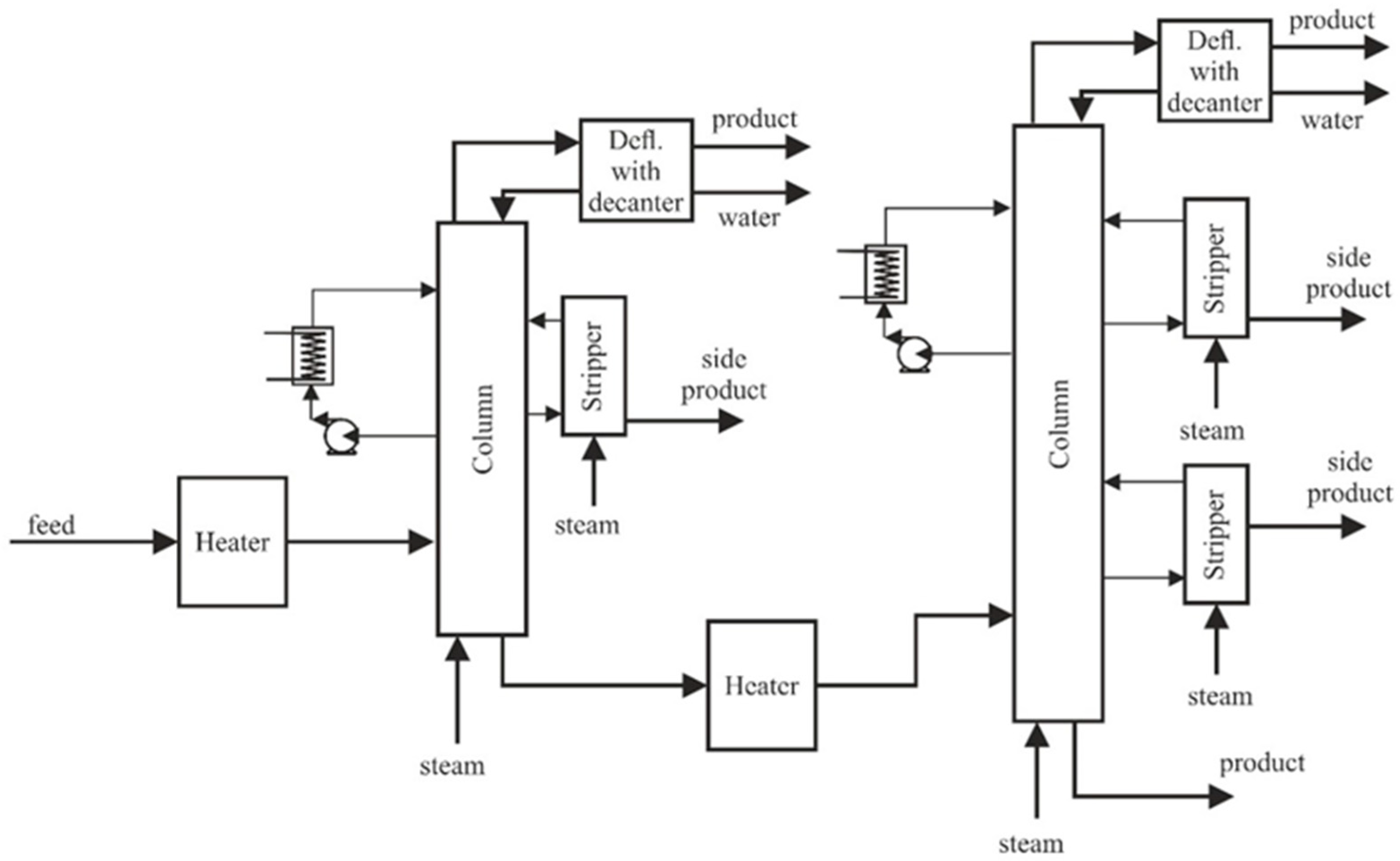
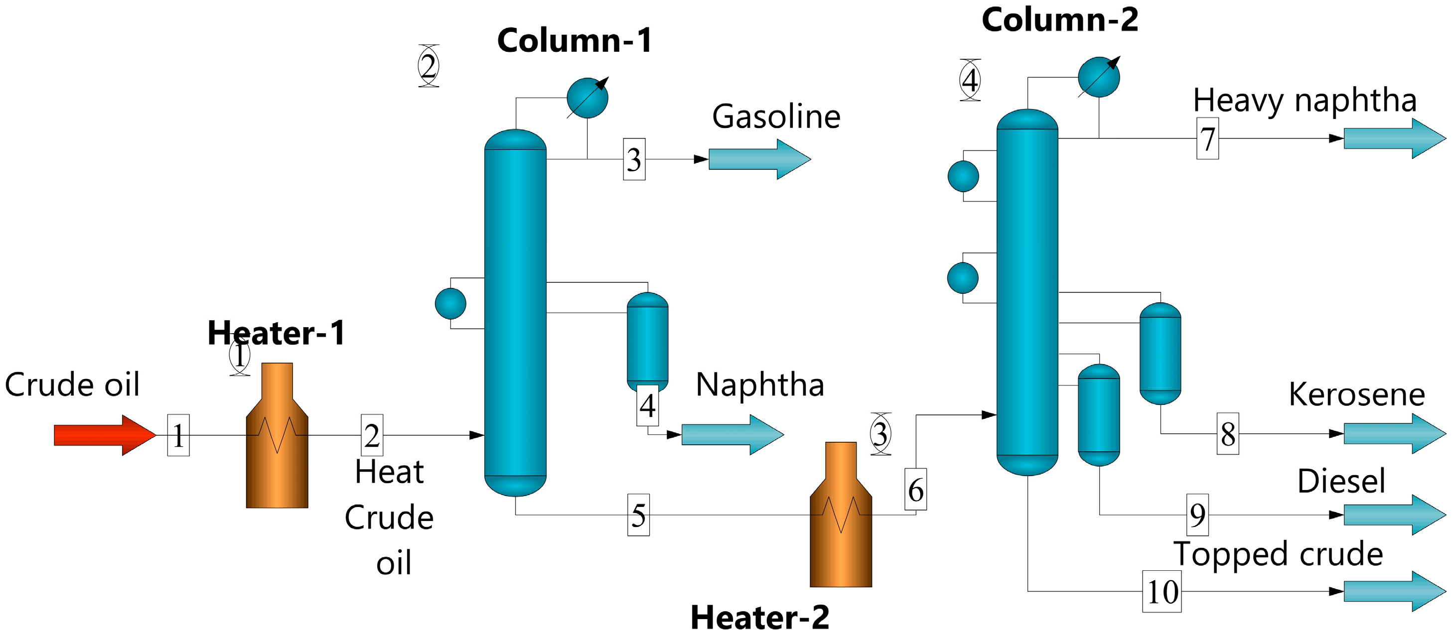
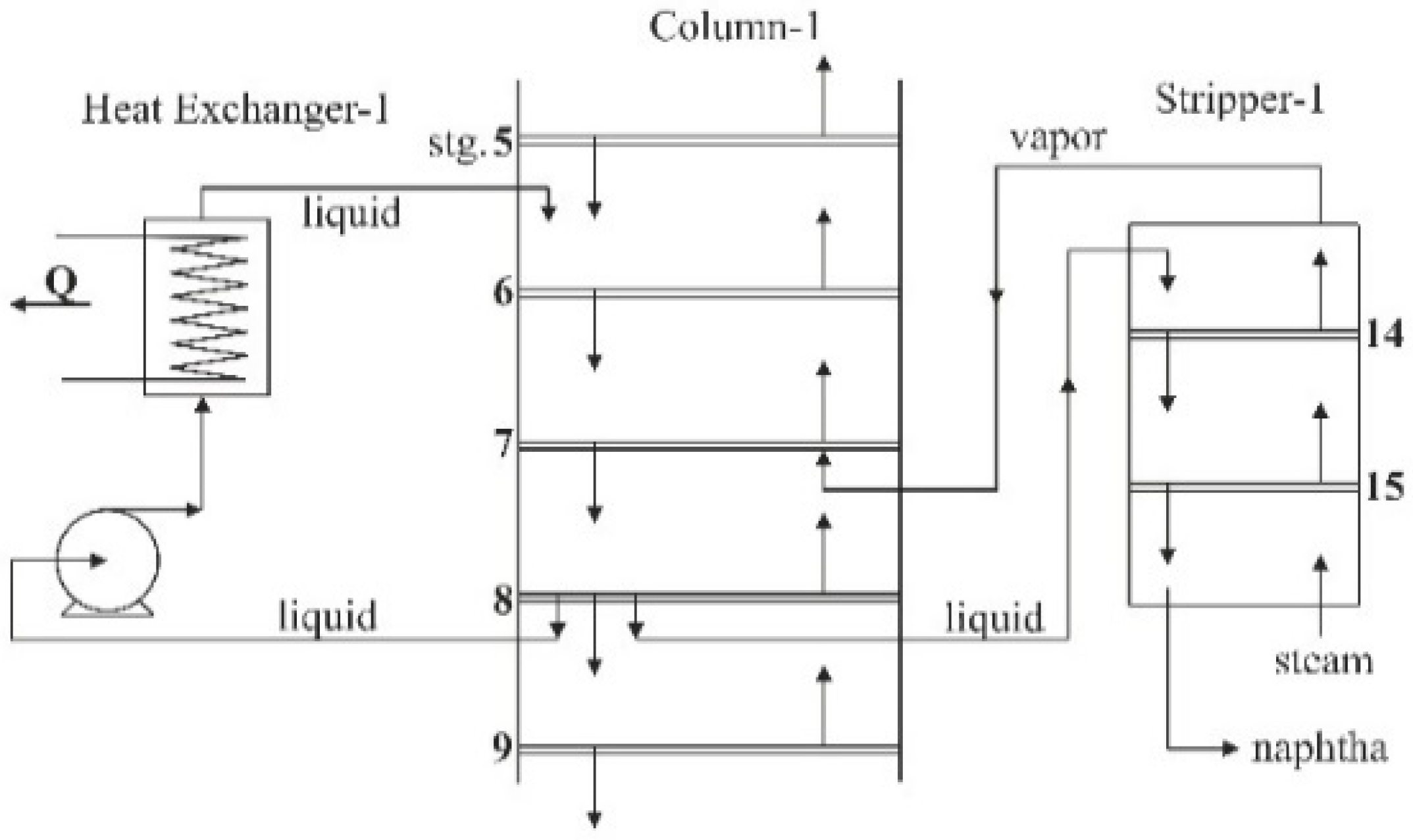
2. Modelling
- A poorly specified feed will result in instabilities in the distillation model. A feed that is very hot will greatly increase the vapor flows on trays above the feed point. On the other hand, a cool feed will increase liquid flows on lower trays. In extreme cases, these conditions can make convergence impossible.
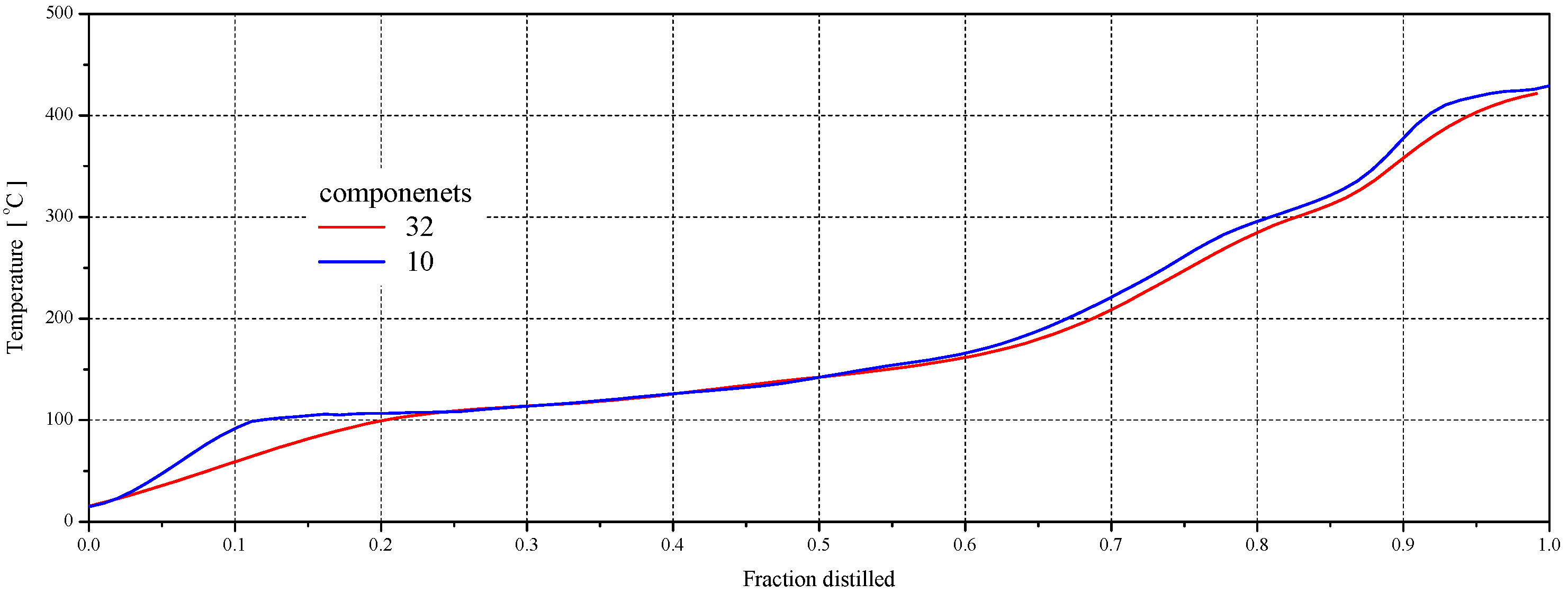
- The poor selection of components for a feed can also cause problems. If components with large differences in volatilities are present (in high concentrations), the distillation model may not give realistic results. The thermodynamic models have difficulty predicting equilibrium conditions under these conditions.
- Fixing the parameters of the reboiler and the condenser (vapor pressures and liquid distillate, efficiencies, reflux ratio, liquid subcooling, bottom’s product rate);
- An increase/decrease in the number of trays;
- Specification of the stream flow and its composition for a given tray;
- Specification of the parameters of each of the trays (pressure, vapor product flow rate, liquid product flow rate, interheater duty, Murphree vapor efficiency).
- For the whole column: tray number, temperature, liquid and vapor flow rate, liquid and vapor enthalpy, reboiler and condenser duty (that is, the value of heat absorbed or desorbed in a period of time);
- For each of the trays: temperature, pressure, liquid and vapor composition, flow rate and enthalpy of internal liquid and vapor, optional feed stream, optional side-stream of liquid and vapor (that is, the flow rate of liquid and vapor products derived from a given tray).
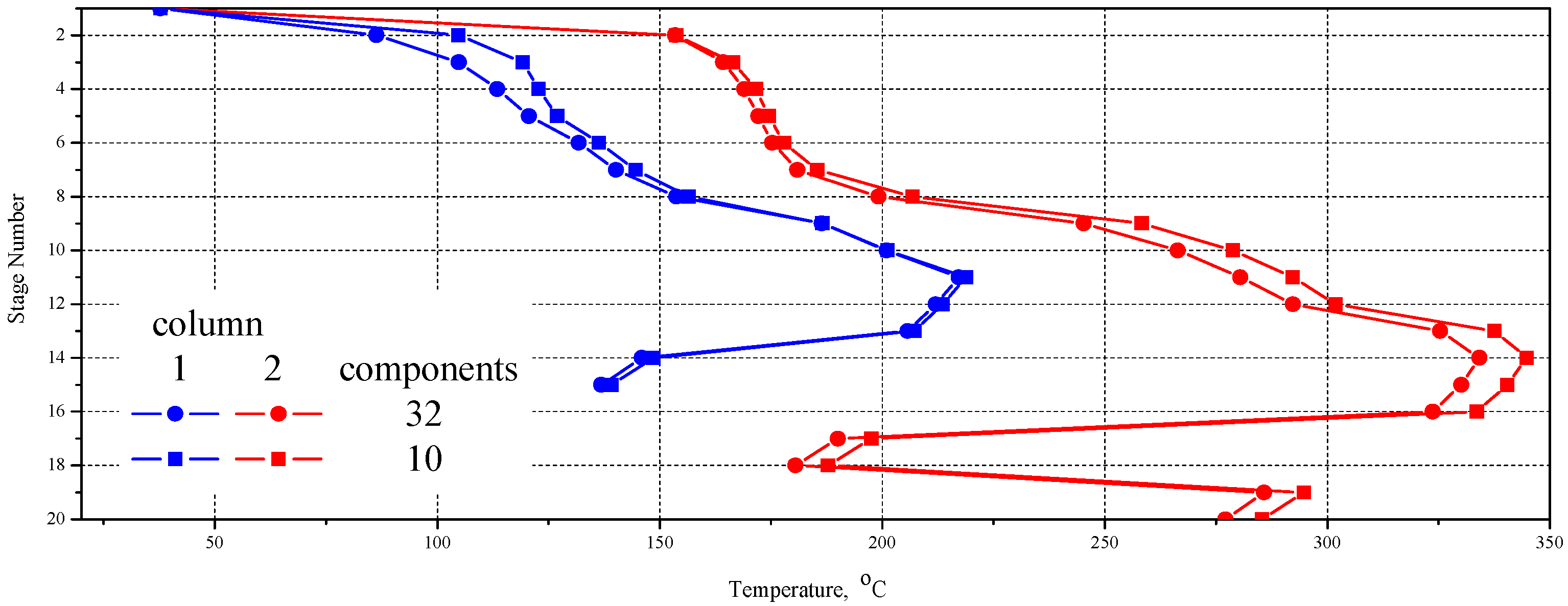
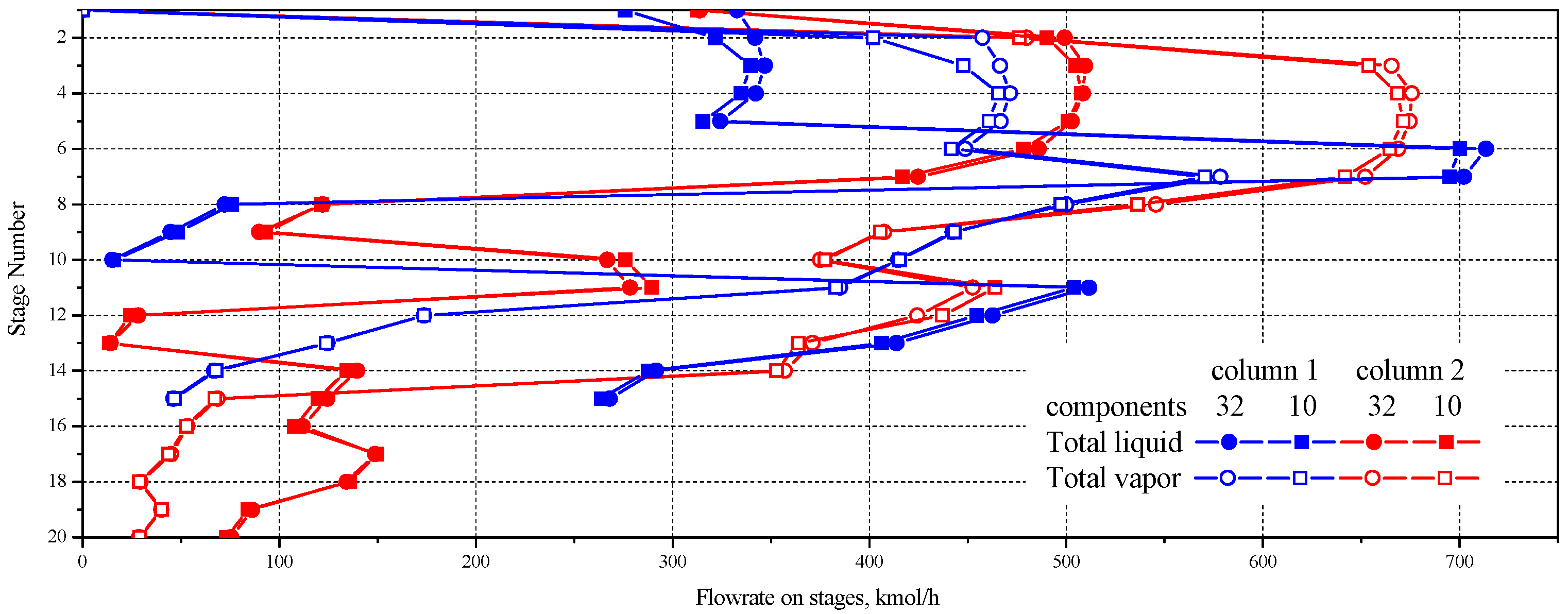
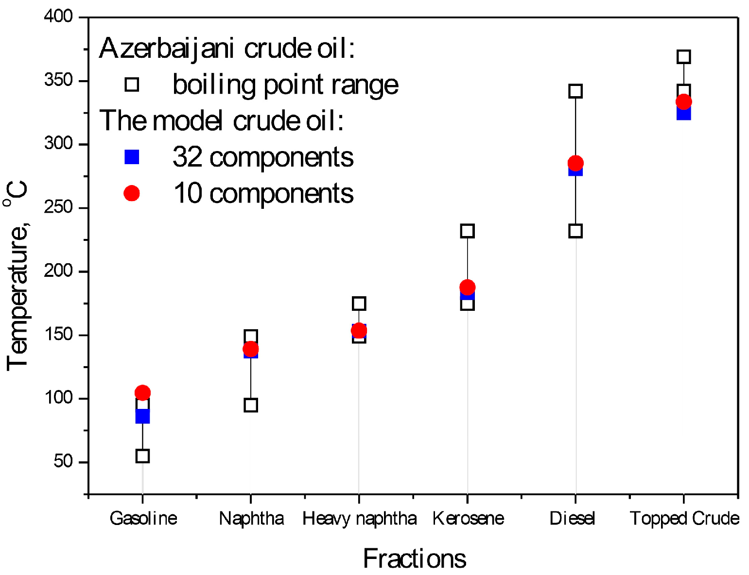
3. Results
4. Conclusions
Author Contributions
Funding
Data Availability Statement
Conflicts of Interest
References
- Li, Q.; Li, Q.; Han, Y. A Numerical Investigation on Kick Control with the Displacement Kill Method during a Well Test in a Deep-Water Gas Reservoir: A Case Study. Processes 2024, 12, 2090. [Google Scholar] [CrossRef]
- Li, Q.; Li, Q.; Wang, F. The Carrying Behavior of Water-Based Fracturing Fluid in Shale Reservoir Fractures and Molecular Dynamics of Sand-Carrying Mechanism. Processes 2024, 12, 2051. [Google Scholar] [CrossRef]
- Vilmar, S.; da Silva, E.A. Steady-State, Modeling of Equilibrium Distillation. In Distillation—Innovative Applications and Modeling; Mendes, M.F., Ed.; InTech: London, UK, 2017. [Google Scholar] [CrossRef]
- Sorel, E. La Rectification de l’Alcohol; Gauthiers-Villard: Paris, France, 1983. [Google Scholar]
- Hausbrand, E. Die Wirkungsweise der Rectifier and Distiller Apparate; Springer Verlag: Berlin, Germany, 1983. [Google Scholar]
- Hanson, N.; Duffin, J.H.; Sommerville, G.F. Computation of Multistage Separation Processes; Reinhold: New York, NY, USA, 1962. [Google Scholar] [CrossRef]
- Holland, C.D. Multicomponent Distillation; Prentice Hall: Engelwood Cliffs, NJ, USA, 1963. [Google Scholar]
- Renon, H.; Asselineau, L.; Cohen, G.; Raimbault, C. Calcul sur Ordinateur des Equilibres Liquid-Vapeur et Liquid-Liquide; Editions Technip: Paris, France, 1971. [Google Scholar]
- Malanowski, S. Równowaga Ciecz-Para; PWN: Warsaw, Poland, 1974. [Google Scholar]
- Renon, H.; Prausnitz, J.M. Local Compositions in Thermodynamic Excess Functions for Liquid Mixtures. AIChE J. 1968, 14, 135–144. [Google Scholar] [CrossRef]
- Chemstations Inc. Houston, TX, USA. Available online: https://chemstations.com/ (accessed on 26 September 2024).
- AspenTech UK Ltd. Sheraton House, Castle Park, Cambridge, UK. Available online: https://www.aspentech.com/en/ (accessed on 26 September 2024).
- Malanowski, S.; Gierycz, P.; Rauk, J.; Wiśniewska, B. Pakiet Programów Komputerowych do Modelowania i Optymalizacji Procesu Destylacji [A Package of Programs for Calculating Distillation Processes]. Przem. Chem. 1990, 69, 342–346. [Google Scholar]
- Mittal, V.; Zhang, J.; Yang, X.; Xu, Q. E3 analysis for crude and vacuum distillation system. Chem. Eng. Technol. 2011, 34, 1854–1863. [Google Scholar] [CrossRef]
- Gu, W.; Huang, Y.; Wang, K.; Zhang, B.; Chen, Q.; Hui, C.W. Comparative analysis and evaluation of three crude oil vacuum distillation processes for process selection. Energy 2014, 76, 559–571. [Google Scholar] [CrossRef]
- Seo, J.W.; Oh, M.; Lee, T.H. Design optimisation of crude oil distillation. Chem. Eng. Technol. 2000, 23, 157–164. [Google Scholar] [CrossRef]
- Gu, W.; Wang, K.; Huang, Y.; Zhang, B.; Chen, Q.; Hui, C.W. Energy optimization for a multistage crude oil distillation process. Chem. Eng. Technol. 2015, 38, 1243–1253. [Google Scholar] [CrossRef]
- Inamdar, S.V.; Gupta, S.K.; Saraf, D.N. Multi-objective optimization of an industrial crude distillation unit using the elitist non-dominated sorting genetic algorithm. Chem. Eng. Res. Des. 2004, 82, 611–623. [Google Scholar] [CrossRef]
- Ibrahim, D.; Jobson, M.; Li, J.; Guill, G. Optimal design of flexible heat-integrated crude oil distillation units using surrogate models. Chem. Eng. Res. Des. 2020, 165, 280–297. [Google Scholar] [CrossRef]
- Motlaghi, S.; Jalali, F.; Ahmadabadi, M.N. An expert system design for a crude oil distillation column with the neural networks model and the process optimization using genetic algorithm framework. Expert Syst. Appl. 2008, 35, 1540–1545. [Google Scholar] [CrossRef]
- Ochoa-Estopier, L.M.; Jobson, M.; Smith, R. Operational optimization of crude oil distillation systems using artificial neural networks. Comput. Chem. Eng. 2013, 59, 178–185. [Google Scholar] [CrossRef]
- Osuolale, F.N.; Zhang, J. Energy efficiency optimization for distillation column using artificial neural network models energy efficiency optimization for distillation column using artificial neural network models. Energy 2016, 106, 562–578. [Google Scholar] [CrossRef]
- Basak, K.; Abhilash, K.S.; Ganguly, S.; Saraf, D.N. On-line optimization of a crude distillation unit with constraints on product properties. Ind. Eng. Chem. Res. 2002, 41, 1557–1568. [Google Scholar] [CrossRef]
- Huang, X.; Zhao, T.; Li, N.; Ma, Z.; Song, L.; Li, J. Emission-reductive and multi-objective coordinative optimization of binary feed for atmospheric and vacuum distillation unit. China Pet. Process. Petrochem. Technol. 2017, 19, 101–112. [Google Scholar]
- Foo, D.C.Y.; Chemmangattuvalappil, N.; Ng, D.K.S.; Elyas, R.; Chen, C.-L.; Elms, R.D.; Lee, H.-Y.; Chien, I.-L.; Chong, S.; Chong, C.H. Chemical Engineering Process Simulation, 2nd ed.; Elsevier: Amsterdam, The Netherlands, 2022. [Google Scholar] [CrossRef]
- More, R.K.; Bulasara, V.K.; Uppaluri, R.; Banjara, V.R. Optimization of crude distillation system using Aspen Plus: Effect of binary feed selection on grass-root design. Chem. Eng. Res. Des. 2010, 88, 121–134. [Google Scholar] [CrossRef]
- Ibrahim, D.; Jobson, M.; Guille, G. Optimization-based design of crude oil distillation units using rigorous simulation models. Ind. Eng. Chem. Res. 2017, 56, 6728–6740. [Google Scholar] [CrossRef]
- Loper, M.L. Modeling and Simulation in the Systems Engineering Life Cycle: Core Concepts and Accompanying Lectures, 9th ed.; Springer: London, UK, 2015. [Google Scholar] [CrossRef]
- Denimal, E.; Nechak, L.; Sinou, J.; Nacivet, S. Kriging surrogate models for predicting the complex eigenvalues of mechanical systems subjected to friction-induced vibration. Shock Vib. 2016, 1–22. [Google Scholar] [CrossRef]
- H’ng, S.X.; Ng, L.Y.; Ng, D.K.S.; Andiappan, V. Optimisation of Vacuum Distillation Units in Oil Refineries Using Surrogate Models. Process. Integr. Optim. Sustain. 2024, 8, 351–373. [Google Scholar] [CrossRef]
- Gierycz, P. Calculation of petroleum processes using the modified distillation package. Polish J. Chem. 2006, 80, 13–25. [Google Scholar]


| No. | 32 Component Mixture | 10 Component Mixture | ||||
|---|---|---|---|---|---|---|
| Component Name | Mass Fraction | Boiling Point | Component Name | Mass Fraction | Boiling Point | |
| 1 | Isobutane | 0.004682 | −11.7 | Isobutane | 0.004682 | −11.72 |
| 2 | Cyclopentane | 0.008477 | 49.25 | |||
| 3 | Benzene | 0.009462 | 80.1 | |||
| 4 | Cyclohexane | 0.024641 | 80.72 | Cyclohexane | 0.057759 | 80.7 |
| 5 | 1,1-Dimethylcyclopentane | 0.024641 | 87.85 | |||
| 6 | 2,2-Dimethylhexane | 0.024641 | 106.89 | |||
| 7 | Toluene | 0.024641 | 110.63 | Toluene | 0.034103 | 110.63 |
| 8 | n-Octane | 0.024641 | 125.7 | n-Octane | 0.119611 | 125.68 |
| 9 | Ethylcyclohexane | 0.024641 | 131.8 | |||
| 10 | m-Xylene | 0.024641 | 139.12 | |||
| 11 | Styrene | 0.024641 | 145.16 | |||
| 12 | n-Nonane | 0.024641 | 150.82 | |||
| 13 | n-Propylbenzene | 0.024641 | 159.24 | |||
| 14 | 1-Ethyl-3-Methylbenzene | 0.030520 | 161.33 | |||
| 15 | 1-Ethyl-4-Methylbenzene | 0.020668 | 162.01 | 1-Ethyl-4-Methylbenzene | 0.121138 | 162.01 |
| 16 | 1,2,4-Trimethylbenzene | 0.020668 | 169.38 | |||
| 17 | 1-Decene | 0.021047 | 170.6 | 1-Decene | 0.021047 | 170.6 |
| 18 | n-Decane | 0.021047 | 174.15 | |||
| 19 | Naphthalene | 0.054674 | 217.99 | Naphthalene | 0.079315 | 217.99 |
| 20 | n-Pentadecane | 0.056662 | 270.75 | |||
| 21 | n-Hexadecane | 0.057657 | 286.9 | |||
| 22 | n-Heptadecane | 0.056662 | 302.15 | n-Heptadecane | 0.221346 | 302.15 |
| 23 | n-Octadecane | 0.030092 | 317.0 | |||
| 24 | n-Nonadecane | 0.020274 | 330.0 | |||
| 25 | Eicosane | 0.020274 | 343.0 | |||
| 26 | n-Tetracosane | 0.045817 | 391.0 | |||
| 27 | n-Pentacosane | 0.045817 | 401.9 | |||
| 28 | n-Hexacosane | 0.045818 | 412.2 | |||
| 29 | n-Heptacosane | 0.045818 | 422.1 | n-Heptacosane | 0.295181 | 422.1 |
| 30 | n-Octacosane | 0.045818 | 435.6 | |||
| 31 | n-Nonacosane | 0.045818 | 440.9 | |||
| 32 | Triacontane | 0.045818 | 449.7 | Triacontane | 0.045818 | 449.7 |
| Configuration | Process Parameters | |
|---|---|---|
| Column-1 | Number of trays (including a dephlegmator—tray no. 1)—13 | Pressure at the top of the column 3.65 bar, pressure drop in the column 0.14 bar |
| Feed tray no. 11 | Feed stream (29.7% vapor, 70.3% liquid): total flow 121,171 kg/h (813 kmol/h), temperature before heater 20.0 °C, temperature after heater 204.4 °C, pressure 3999 bar | |
| Tray no. 10 | Flow of liquid 2.65 m3/h | |
| Tray no. 13 | Flow of liquid 11.3 m3/h | |
| Column bottom fed with steam | Steam: total flow 1362.32 kg/h (75.6 kmol/h), temperature 168.3 °C, pressure 7.9 bar | |
| Dephlegmator | Fully condensing with decantation | Cooling to temperature 37.8 °C Pressure 3.3 bar |
| Stripper-1 | Number of trays 2 | |
| Powered (liquid) from tray no. 8; Returned vapors to tray no. 7 | Flow of exhausted liquid 35.9 m3/h | |
| Stripper bottom fed with steam | Steam: total flow 408.69 kg/h (22.7 kmol/h), temperature 168.3 °C, pressure 7.9 bar | |
| Pump with the Heat Exchanger-1 | Liquid withdrawn from tray no. 8, Liquid returned to tray no. 6, | Flow 34.3 m3/h |
| Heat duty (heat flux received) | −5275.3 MJ/h |
| Configuration | Process Parameters | |
|---|---|---|
| Column-2 | Number of trays (including a dephlegmator—tray no. 1)–16 | Pressure at the top of the column 1.59 bar, pressure drop in the column 0.14 bar |
| Feed tray no. 14 | Feed stream (34.8% vapor, 65.2% liquid): total flow 90,401.66 kg/h (421 kmol/h), temperature before heater 205.7 °C, temperature after heater 315.6 °C, pressure 1.59 bar | |
| Tray no. 13 | Flow of liquid 48.6 m3/h | |
| Column bottom fed with steam | Steam: total flow 735.64 kg/h (40.8 kmol/h), temperature 168.3 °C, pressure 7.9 bar | |
| Dephlegmator | Fully condensing with decantation | Cooling to temperature 37.8 °C Pressure 1.38 bar |
| Upper Stripper | Number of trays 2 | |
| Powered (liquid) from tray no. 8 Returned vapors to tray no. 7 | Flow of exhausted liquid 25.04 m3/h | |
| Stripper bottom fed with steam | Steam: total flow 272.46 kg/h (15.1 kmol/h), temperature 168.3 °C, pressure 7.9 bar | |
| Lower Stripper | Number of trays 2 | |
| Powered (liquid) from tray no. 12; Returned vapors to tray no.11 | Flow of exhausted liquid 24.09 m3/h | |
| Stripper bottom fed with steam | Steam: total flow 326.95 kg/h (18.1 kmol/h), temperature 168.3 °C, pressure 7.9 bar | |
| Pump with the Heat Exchanger-2 | Liquid withdrawn from tray no. 12; Liquid returned to tray no. 10 | Flow 31.1 m3/h |
| Heat duty (heat flux received) | −7712.5 MJ/h |
| Stg | Temp | Pres | Liquid | Vapor | Feeds | Product | Duties |
|---|---|---|---|---|---|---|---|
| °C | bar | kg/h | kg/h | kg/h | kg/h | MJ/h | |
| 1 | 37.8 | 3.31 | 22,974.77 | 1963.75 | −15,330 | ||
| 1730.71 (1) | |||||||
| 2 | 86.3 | 3.65 | 26,320.90 | 26,668.78 | |||
| 3 | 104.8 | 3.67 | 28,311.44 | 30,014.92 | |||
| 4 | 113.5 | 3.68 | 29,203.78 | 32,005.46 | |||
| 5 | 120.6 | 3.69 | 29,060.35 | 32,897.75 | |||
| 6 | 131.8 | 3.70 | 69,313.23 | 32,754.35 | −5275 | ||
| 67.5 | 27,584.07 (2) | ||||||
| 7 | 140.2 | 3.72 | 70,300.00 | 45,423.29 | 4728.94 (3) | ||
| 8 | 153.7 | 3.73 | 7690.67 | 41,681.16 | 27,584.07 (4) | ||
| 33,166.14 (5) | |||||||
| 9 | 186.4 | 3.74 | 5490.96 | 39,821.95 | |||
| 10 | 201.0 | 3.75 | 2179.25 | 37,622.23 | |||
| 11 | 217.2 | 3.77 | 101,358.00 | 34,310.51 | 121,171.00 (6) | 8709 | |
| 12 | 212.0 | 3.78 | 96,027.38 | 12,318.19 | |||
| 13 | 205.7 | 3.75 | 6987.65 | 1362.32 (7) | 90,401.66 | ||
| Stripper-1 | |||||||
| 14 | 146.0 | 3.73 | 31,165.39 | 33,166.14 (5) | 4728.94 (3) | ||
| 15 | 136. 9 | 3.73 | 2728.13 | 408.69 (8) | 28,845.83 | ||
| Stg | Temp | Pres | Liquid | Vapor | Feeds | Product | Duties |
|---|---|---|---|---|---|---|---|
| °C | bar | kg/h | kg/h | kg/h | kg/h | MJ/h | |
| 1 | 37.8 | 3.31 | 20,863.00 | 2245.03 | 1736.67 (1) | −15,190 | |
| 2 | 104.8 | 3.65 | 26,865.29 | 24,844.24 | |||
| 3 | 119.2 | 3.67 | 28,848.87 | 30,846.51 | |||
| 4 | 122.7 | 3.68 | 28,891.03 | 32,830.09 | |||
| 5 | 127.0 | 3.69 | 28,266.12 | 32,872.25 | |||
| 6 | 136.4 | 3.70 | 67,901.73 | 32,247.34 | 27,116.26 (2) | −5275 | |
| 7 | 144.6 | 3.72 | 69,452.30 | 44,766.87 | 4804.15 (3) | ||
| 8 | 156.5 | 3.73 | 8061.24 | 41,513.29 | 27,116.26 (4) | ||
| 32,733.00 (5) | |||||||
| 9 | 186.6 | 3.74 | 5832.61 | 39,971.43 | |||
| 10 | 201.2 | 3.75 | 2231.77 | 37,742.80 | |||
| 11 | 218.8 | 3.77 | 101,364.61 | 34,141.96 | 121,000.00 (6) | 9280 | |
| 12 | 213.5 | 3.78 | 95,970.49 | 12,274.79 | |||
| 13 | 207.2 | 3.79 | 6880.67 | 90,451.76 | 1362.32 (7) | ||
| Stripper-1 | |||||||
| 14 | 148.5 | 3.73 | 30,690.70 | 32,733.00 (5) | 4804.15 (3) | ||
| 15 | 139.2 | 3.73 | 2761.72 | 408.69 (8) | 28,337.55 | ||
| Stg | Temp | Pres | Liquid | Vapor | Feeds | Product | Duties |
|---|---|---|---|---|---|---|---|
| °C | bar | kg/h | kg/h | kg/h | kg/h | M J/h | |
| 1 | 37.8 | 1.38 | 35,162.28 | 10,248.66 | −29,230 | ||
| 1345.15 (1) | |||||||
| 2 | 153.5 | 1.59 | 58,822.68 | 46,755.74 | |||
| 3 | 164.2 | 1.60 | 61,566.38 | 70,416.13 | |||
| 4 | 169.0 | 1.61 | 62,408.21 | 73,159.84 | |||
| 5 | 172.1 | 1.62 | 62,402.53 | 74,001.67 | |||
| 6 | 175.3 | 1.63 | 60,882.52 | 73,996.00 | |||
| 7 | 180.9 | 1.64 | 54,422.75 | 72,476.00 | 4069.95 (2) | ||
| 8 | 199.2 | 1.64 | 13,387.77 | 61,946.29 | 24,739.74 (3) | ||
| 9 | 245.2 | 1.65 | 13,208.92 | 50,651.14 | |||
| 10 | 266.4 | 1.66 | 59,971.93 | 50,472.29 | 24,513.83 (4) | −7712 | |
| 11 | 280.5 | 1.67 | 64,499.00 | 67,716.34 | 4722.86 (5) | ||
| 12 | 292.3 | 1.68 | 6995.73 | 67,520.58 | 24,513.83 (6) | ||
| 24,013.42 (7) | |||||||
| 13 | 325.4 | 1.69 | 4494.16 | 58,549.20 | |||
| 14 | 334.2 | 1.70 | 45,812.93 | 56,047.64 | 90,401.66 (8) | 10,570 | |
| 15 | 330.1 | 1.71 | 42,775.86 | 6964.74 | |||
| 16 | 323.7 | 1.72 | 3927.67 | 735.64 (9) | 39,583.62 | ||
| Upper Stripper | |||||||
| 17 | 190.0 | 1.64 | 22,779.93 | 24,739.74 (3) | 4069.95 (2) | ||
| 18 | 180.5 | 1.64 | 2110.03 | 272.46 (11) | 20,942.28 (10) | ||
| Lower Stripper | |||||||
| 19 | 235.8 | 1.68 | 21,920.12 | 24,013.42 (7) | 4722.86 (5) | ||
| 20 | 277.1 | 1.68 | 2630.02 | 326.95 (13) | 19,616.96 (12) | ||
| Stg | Temp | Pres | Liquid | Vapor | Feeds | Product | Duties |
|---|---|---|---|---|---|---|---|
| °C | bar | kg/h | kg/h | kg/h | kg/h | M J/h | |
| 1 | 37.8 | 1.38 | 35,228.52 | 10,007.69 | −29,200 | ||
| 1344.91 (1) | |||||||
| 2 | 153.6 | 1.59 | 58,325.00 | 46,580.76 | |||
| 3 | 166.5 | 1.60 | 61,388.17 | 69,677.28 | |||
| 4 | 171.6 | 1.61 | 62,317.86 | 72,740.41 | |||
| 5 | 174.5 | 1.62 | 61,825.65 | 73,670.11 | |||
| 6 | 177.9 | 1.63 | 59,331.65 | 73,177.90 | |||
| 7 | 185.4 | 1.64 | 52,836.81 | 70,683.89 | 3888.88 (2) | ||
| 8 | 206.8 | 1.64 | 18,595.05 | 60,300.18 | 25,230.26 (3) | ||
| 9 | 259.3 | 1.65 | 19,984.38 | 51,288.73 | |||
| 10 | 278.8 | 1.66 | 64,602.48 | 52,678.07 | 24,510.45 (4) | −7712 | |
| 11 | 292.2 | 1.67 | 69,126.58 | 72,785.78 | 4950.83 (5) | ||
| 12 | 301.9 | 1.63 | 6227.98 | 72,359.00 | 24,510.45 (6) | ||
| 24,210.37 (7) | |||||||
| 13 | 337.6 | 1.69 | 4469.91 | 58,181.18 | |||
| 14 | 344.8 | 1.70 | 45,398.63 | 56,423.11 | 90,451.76 (8) | 14,570 | |
| 15 | 340.4 | 1.71 | 42,399.59 | 6900.08 | |||
| 16 | 333.6 | 1.72 | 3901.03 | 735.64 (9) | 39,234.00 | ||
| Upper Stripper | |||||||
| 17 | 197.5 | 1.64 | 23,364.50 | 25,230.26 (3) | 3888.88 (2) | ||
| 18 | 187.8 | 1.64 | 2023.06 | 272.46 (11) | 21,613.82 (10) | ||
| Lower Stripper | |||||||
| 19 | 294.7 | 1.68 | 22,047.92 | 24,210.37 (7) | 4950.83 (5) | ||
| 20 | 235.3 | 1.68 | 2788.40 | 326.95 (13) | 19,586.38 (12) | ||
| Equip. No. | 1 | 3 | |
| Name | Heater-1 | Heater-2 | |
| Temperature out | °C | 204.44 | 315.56 |
| Heat absorbed | MJ/h | 55,339.07 | 35,896.19 |
| Fueal usage (SCF) | 77,705.35 | 50,404.28 |
Disclaimer/Publisher’s Note: The statements, opinions and data contained in all publications are solely those of the individual author(s) and contributor(s) and not of MDPI and/or the editor(s). MDPI and/or the editor(s) disclaim responsibility for any injury to people or property resulting from any ideas, methods, instructions or products referred to in the content. |
© 2024 by the authors. Licensee MDPI, Basel, Switzerland. This article is an open access article distributed under the terms and conditions of the Creative Commons Attribution (CC BY) license (https://creativecommons.org/licenses/by/4.0/).
Share and Cite
Krzywda, R.; Gierycz, P.; Makowski, Ł.; Poświata, A. Calculation of Crude Oil Processes Using Simplified Model Mixture. Energies 2024, 17, 6025. https://doi.org/10.3390/en17236025
Krzywda R, Gierycz P, Makowski Ł, Poświata A. Calculation of Crude Oil Processes Using Simplified Model Mixture. Energies. 2024; 17(23):6025. https://doi.org/10.3390/en17236025
Chicago/Turabian StyleKrzywda, Roman, Paweł Gierycz, Łukasz Makowski, and Artur Poświata. 2024. "Calculation of Crude Oil Processes Using Simplified Model Mixture" Energies 17, no. 23: 6025. https://doi.org/10.3390/en17236025
APA StyleKrzywda, R., Gierycz, P., Makowski, Ł., & Poświata, A. (2024). Calculation of Crude Oil Processes Using Simplified Model Mixture. Energies, 17(23), 6025. https://doi.org/10.3390/en17236025