Article

High-Capacity Energy Storage Devices Designed for Use in Railway Applications

1
Łukasiewicz Research Network, Electrotechnical Testing Laboratory, Institute of Technology, Warszawska 181, 61055 Poznan, Poland
2
Faculty of Civil and Transport Engineering, Doctoral School, Poznan University of Technology, Piotrowo 3, 60965 Poznan, Poland
3
Faculty of Chemical Technology, Institute of Chemistry and Electrochemistry, Poznan University of Technology, Berdychowo 4, 60965 Poznan, Poland
4
Faculty of Civil Engineering and Transport, Institute of Powertrains and Aviation, Poznan University of Technology, Piotrowo 3, 60965 Poznan, Poland
*
Author to whom correspondence should be addressed.
Energies 2024, 17(23), 5904; https://doi.org/10.3390/en17235904
Submission received: 31 October 2024 / Revised: 21 November 2024 / Accepted: 22 November 2024 / Published: 25 November 2024

Abstract

:
This paper investigates the application of high-capacity supercapacitors in railway systems, with a particular focus on their role in energy recovery during braking processes. The study highlights the potential for significant energy savings by capturing and storing energy generated through electrodynamic braking. Experimental measurements conducted on a diesel–electric multiple unit revealed that approximately 28.3% to 30.5% of the energy could be recovered from the traction network, regardless of the type of drive used—whether electric or diesel. This research also explores the integration of starch-based carbon as an electrode material in supercapacitors, offering an innovative, sustainable alternative to traditional graphite or graphene electrodes. The carbon material was obtained through a simple carbonization process, with experimental results demonstrating a material capacity of approximately 130 F/g. To quantify the energy recovery, calculations were made regarding the mass and power requirements of the supercapacitors. For the tested vehicle, it was estimated that around 28.7% of the energy could be recovered during the braking process. To store 15 kWh of energy, the total mass of the capacitors required is approximately 245.1 kg. The study emphasizes the importance of increasing voltage levels in railway systems, which can enhance energy transmission and utilization efficiency. Additionally, the paper discusses the necessity of controlled energy discharge, allowing for the flexible management of energy release to meet the varying power demands of trains. By integrating high-voltage supercapacitors and advanced materials like starch-based carbon, this research paves the way for more sustainable and efficient railway systems, contributing to the industry’s goals of reducing emissions and improving operational performance. The findings underscore the crucial role of these capacitors in modernizing railway infrastructure and promoting environmentally responsible transportation solutions.

1. Introduction

1.1. Possibility of Energy Saving in Transport

The environment when it comes to vehicles is a major challenge in the development of transport. Manufacturers of machines and vehicles are constantly taking steps to minimize adverse effects on the environment. A helpful tool in this type of work are tests involving real operation conditions, which concern various groups of vehicles [1,2,3]. Determining energy consumption in real test conditions provides reliable results regarding the energy flow and operation of individual elements of the drive system [4,5]. One of the most promising solutions is regenerative braking. The use of braking energy can relieve the load on the electric motors in the drive or the combustion engine. The combustion engine produces emissions that affect and pollute the environment [6,7,8]. These capacitors also support power quality by stabilizing voltage levels, reducing voltage sags and surges, and minimizing harmonic distortion. This ensures a stable power supply for train systems, improving both operational reliability and safety [9,10,11,12].
As railway electrification expands, the integration of high-voltage supercapacitors is crucial for optimizing energy use, promoting environmental sustainability, and driving innovation in the rail industry. Their role in energy storage and power management will continue to support the development of efficient and eco-friendly rail transportation systems [13,14,15,16,17].

1.2. Materials Used in Supercapacitors

Supercapacitors, also known as ultracapacitors or electric double-layer capacitors (EDLCs), store energy through electrostatic charge accumulation rather than electrochemical reactions. The efficiency and performance of a supercapacitor are largely determined by the materials used for the electrodes, as well as the electrolyte that separates them. The basic characteristics of an ideal electrode material include high surface area, good electrical conductivity, and stability under cyclic conditions. Activated carbon is one of the most commonly used electrode materials for supercapacitors due to its high surface area and porosity. Its porous structure allows for maximum charge accumulation on the electrode surface. However, its relatively low conductivity and moderate energy density limit its performance compared to other materials.
Carbon nanotubes (CNTs) are another common electrode material due to their exceptional electrical conductivity, high surface area, and mechanical strength. CNTs enable faster charging and discharging, which is crucial for some high-power applications. However, their high production costs and challenges in scaling up the synthesis are significant drawbacks [18,19,20].
Graphene is a promising material for supercapacitors due to its excellent electrical conductivity, large surface area, and mechanical strength. It allows for both high energy and power densities. Despite these advantages, graphene synthesis can be expensive, and large-scale production remains a challenge [21,22,23,24,25].
Recently, starch-based carbon materials have gained attention as a potential alternative to conventional carbon materials. These materials are synthesized via starch carbonization, offering an environmentally friendly, low-cost option for electrode production. They can offer good electrochemical performance, although their energy and power densities are still being optimized for practical applications [26].
The pressing issue of increases in worldwide use of fossil fuels, in spite of environmental pollution has led to a growing need for solutions. For this reason, rapid growth concerning renewable energy sources and efficient energy storages has started. These include highly effective energy storage devices such as supercapacitors. These are used in everyday electronics as well as in military devices. Evaluating the performance of supercapacitors involves examining their electrochemical properties, which depend on the materials used for the electrodes and electrolytes [27]. The recent advancements in supercapacitor technology focus on charge storage mechanisms and materials for electrodes and electrolytes. The main takeaway is the inclusion of biomaterials in energy storing technologies due to their sustainability, eco-friendliness, degradability, cost-effectiveness, and promising potential (Figure 1).
Biomaterials have emerged as a promising and environmentally friendly option when it comes to developing supercapacitors, providing a contribution to the energy storage technology. These natural or synthetic materials, often derived from living organisms or inspired by biological systems, offer unique structural and chemical properties that make them attractive for use in supercapacitors [28].
One key advantage of biomaterials in supercapacitors is their sustainability. As renewable resources, they can be sourced in an eco-friendly manner, reducing ecological impact in comparison with traditional materials. Additionally, the implementation of biomaterials fits the global trends highlighting green and sustainable energy solutions.
Biomaterials also exhibit remarkable properties that can enhance the performance of supercapacitors. Their high surface area and porosity allow for efficient ion adsorption and charge storage, leading to improved energy storage capabilities. Moreover, some biomaterials possess excellent electrical conductivity and stability, further enhancing the overall efficiency and lifespan of supercapacitor devices. Their ability to break down naturally after their useful life reduces the burden of electronic waste.
The motivation for using starch as a material for supercapacitor electrodes lies not primarily in energy density, but rather in its sustainability, cost-effectiveness, and availability. Although starch does have a lower energy density compared to some conventional electrode materials, it offers several advantages:
Eco-friendliness and renewability—starch is a biodegradable, renewable material, making it an environmentally friendly choice. This is particularly valuable in reducing the ecological impact of energy storage devices, which is a growing concern in material science and engineering.
High power density—starch-derived materials can deliver high power density, which is advantageous in applications where rapid charging and discharging are more critical than overall energy storage capacity.
Cost-effectiveness—starch is an abundant and low-cost material. This can reduce the overall production cost of supercapacitors, making them more accessible for broader applications.
In summary, while starch may have limitations in terms of energy density, it brings unique benefits that align with the goals of sustainability, affordability, and high power output. These qualities make starch a promising candidate for specific supercapacitor applications where these factors outweigh the need for higher energy density.
Metal oxides (e.g., manganese dioxide, nickel oxide) and conductive polymers (e.g., polyaniline, polypyrrole) are also used in hybrid supercapacitors to enhance capacitance and energy density. While these materials provide improved energy storage, they often suffer from limited cycle life and lower power densities than carbon-based electrodes.

1.3. Challenges of Using Supercapacitors in Transport, Particularly Rail

While supercapacitors offer great potential for energy storage in transportation systems, especially in applications such as regenerative braking, there are several challenges that arise when implementing them in rail transportation.
Energy density limitations
Supercapacitors typically have a lower energy density compared to batteries. This means that while they can charge and discharge quickly, they cannot store as much energy in a given volume or weight. For rail applications where large amounts of energy need to be stored and delivered (especially in long trains or heavy operations), this limitation may require the use of additional energy storage systems, such as batteries, in addition to supercapacitors [29].
Cost
While supercapacitors are efficient and have a long cycle life, their cost can be prohibitive, especially for large-scale transportation systems. The use of advanced materials such as graphene or carbon nanotubes can further increase the cost of production. In addition, the need for a large number of capacitors to store sufficient energy for transportation applications increases the initial investment, which can be a barrier to widespread adoption [30,31,32].
Voltage balancing
Supercapacitors often need to be connected in series to achieve higher voltage levels. However, when connected in series, individual capacitors can become unbalanced, reducing the overall system efficiency and lifespan. To address this problem, effective voltage equalization systems are required, which increases the complexity and cost of the system [33].
Temperature sensitivity
Supercapacitors, like all electronic components, are sensitive to extreme temperatures. High temperatures can increase the rate of degradation and shorten the life cycle of supercapacitors, while very low temperatures can affect their performance. Rail transportation systems often operate under variable environmental conditions, making temperature stability a critical issue for the reliability and longevity of supercapacitors [34].
Energy recovery efficiency
While supercapacitors are very efficient at recovering energy, the overall system efficiency is affected by the regenerative braking technology and the type of power conversion systems used. In rail systems, this can be complicated by the need to adapt supercapacitors to both electric and diesel–electric drives with different energy characteristics [35].
Space and weight considerations
In rail transport, space and weight are often at a premium. The use of supercapacitors requires significant installation space, and the weight of the capacitors can also become a factor, especially in heavy trains where large amounts of energy need to be stored. In addition, large capacitors can affect the design of trains, especially in urban transit systems where space is limited [36].
Integration with existing infrastructure
Rail networks are often built on older infrastructure, which may not be optimized for the integration of modern energy storage systems. Integrating supercapacitors into existing rail systems can require significant upgrades to both the electrical systems and control software, which can increase costs and require additional planning and testing.
Controlled energy discharge
Supercapacitors discharge energy very quickly, which makes them ideal for short bursts of power, such as during braking. However, controlled and efficient energy discharge is crucial, particularly in rail systems, where trains have varying energy demands depending on acceleration, speed, and braking conditions. Without sophisticated energy management systems, ensuring that stored energy is effectively used or released back into the grid can be challenging.
While supercapacitors have significant potential for energy recovery and storage in rail transport, they pose a number of challenges that need to be addressed to optimize their performance. Selecting the right electrode materials, such as activated carbon, carbon nanotubes, or starch-based carbon, plays a key role in determining their performance. However, issues such as limited energy density, cost, temperature sensitivity, and integration with existing infrastructure need to be carefully managed. With ongoing advances in materials science and systems engineering, supercapacitors could play an increasingly important role in the future of sustainable rail transport.

2. Methods and Materials

2.1. Synthesis of Carbon Material from Starch

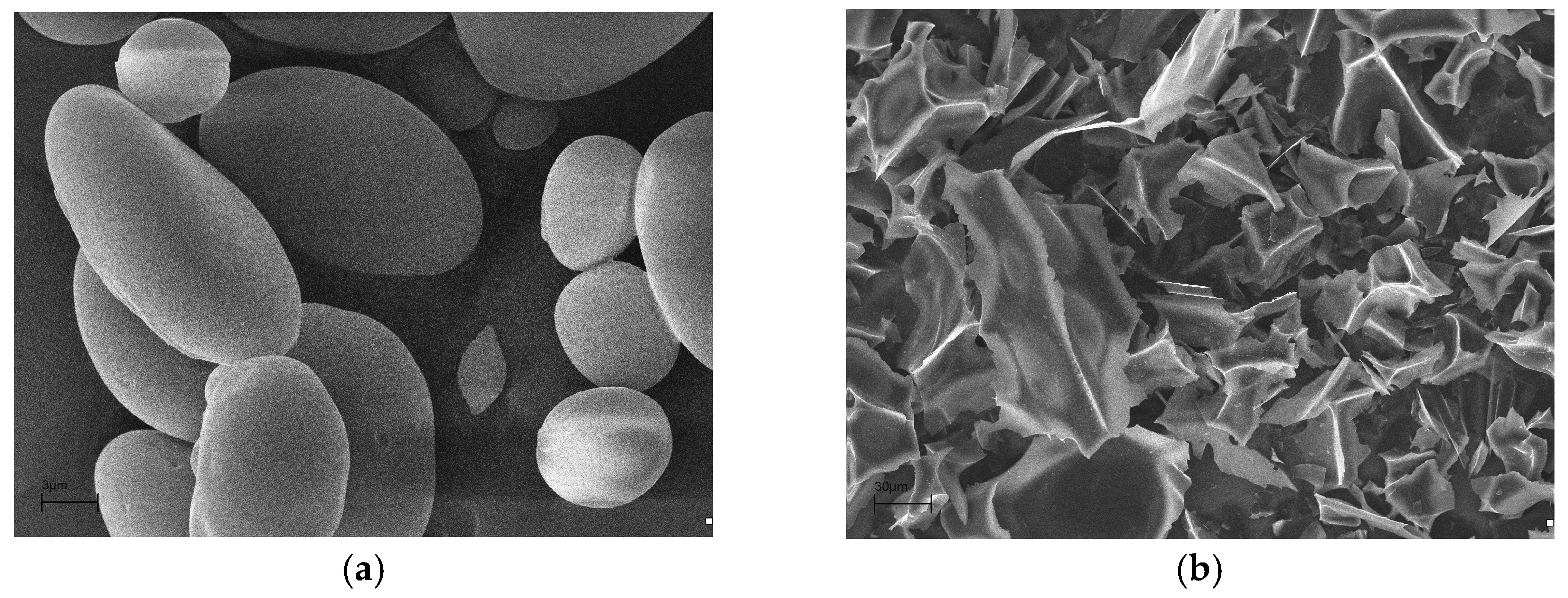
Starch-derived carbonaceous materials are obtained by the carbonisation process. The synthesis takes place in an environment of inert gas such as nitrogen by using a Nabertherm pipe furnace. The obtaining procedure starts with heating the furnace and then carbonisation takes 4 h. Every hour the temperature is increased by 300 °C. The whole process takes just over 6 h. During carbonization, usage of nitrogen gas reaches 50 L/h. In addition, the air in the chamber is replaced by an inert gas before the process begins. A measuring system indicated that technical gas stood for 99.998% of atmosphere during the process. The illustration (Figure 2) depicts the actual structure of the carbon material produced post-starch carbonization, as well as the appearance of the tube after the completion of the process.

2.2. Research Object

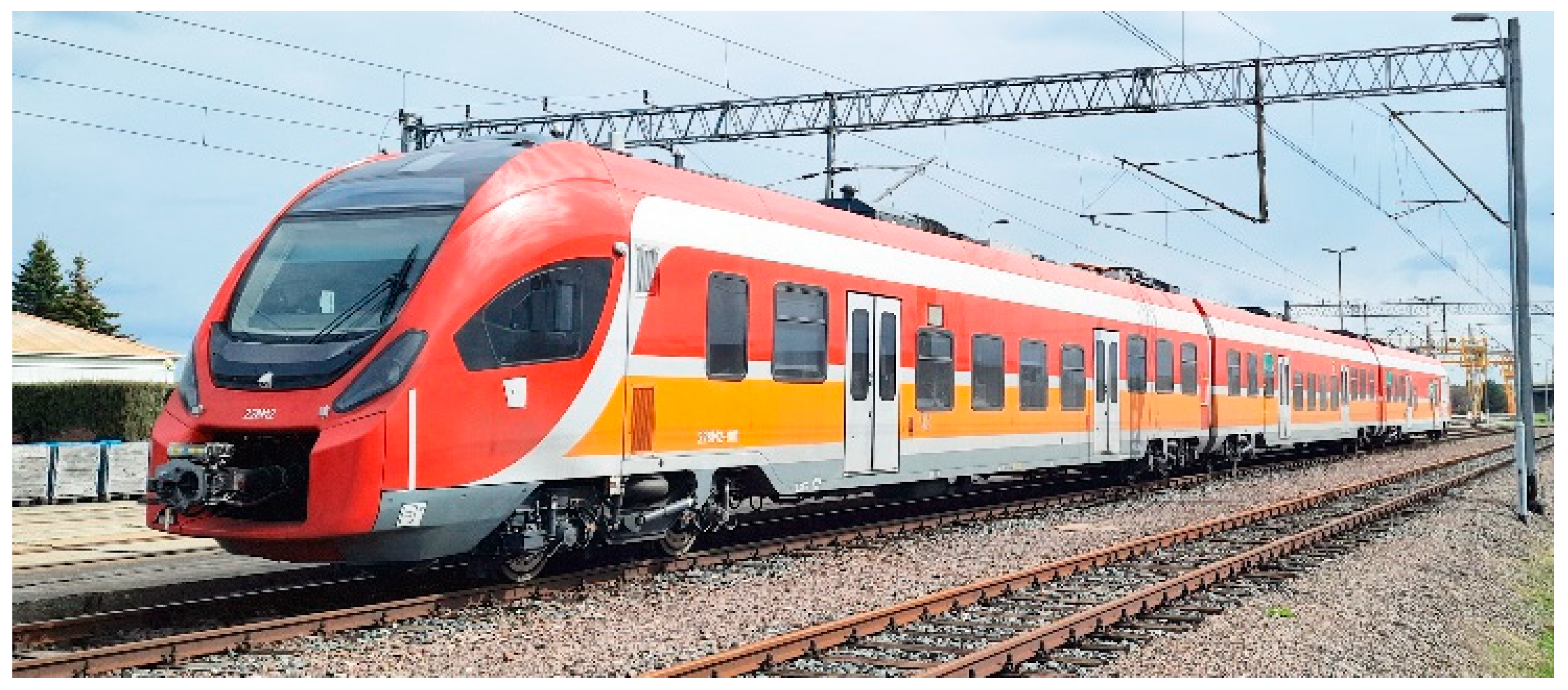
The estimation of the volume of electric energy recoverable by electrodynamic braking was taken on actual runs on the test track. A diesel–electric multiple unit, shown in Figure 3, was chosen for testing. The general characteristics and selected parameters of the test vehicle are shown in Table 1.
The test was performed in real operating conditions on the test track. Based on the tests performed, the necessary data for the selection of supercapacitors were defined. The tests were carried out on the experimental track of the Railway Institute in Zmigrod. Tests were carried out for electric traction up to 160 km/h and diesel traction up to 120 km/h. During each test, the vehicle accelerated at maximum power and then decelerated with maximum braking force to a stop. This provided information on the volume of electrical energy drawn from the overhead line and the energy that could be recovered during electrodynamic braking. The energy recovered in the braking process was transferred to the braking resistors and converted to heat. The recuperation of electrical energy into the overhead line was blocked. The measuring system consisted of current and voltage transducers connected to digital recorders prod. DEWESoft DewesoftX 2024.4. The measuring system included the following:
  • Current and voltage at the pantograph before the main switch;
  • Current and voltage at braking resistors;
  • Current and voltage at the output of traction rectifier;
  • Speed from the GPS device and from sensors installed on the axles.

2.3. Electrochemical Properties

The following components were used to form carbon electrodes: carbon material, binder: polyvinylidene fluoride (PVdF—Sigma Aldrich—St. Louis, MO, USA), acetylene black (Sigma Aldrich—USA). To obtain equal electrode masses, the mixture is formed in an agate mortar. The next step is to transfer the mass to copper interceptors with a unit weight of 4 mg. The electrodes are subjected to a temperature of 105 °C and paired together according to the criterion of the nearest mass value.
To prepare the supercapacitor, the samples were placed in a Swagelok® (Solon, OH, USA) measuring cell. In order to ease electrolyte (2 M Na2SO4—Sigma Aldrich) distribution by gravity flow, a working electrode with lower mass was placed in the position of the lower collector. To avoid unwanted contact between the electrodes a glass fibre isolator is used. After topping up with electrolyte, the system is sealed by adding and using the current collector of the counter electrode [37]. The components of the cell were connected using a dedicated Swagelok® connector.
Using a multi-channel Potentiostat/Galvanostat ZRA 6750 from Gamry Industries (Warminster, PA, USA), the electrochemical properties were assessed. In addition to the conventional method of assessing electrochemical properties by cyclic voltammetry, the equipment also offers other methods such as: linear voltammetry, stripping voltammetry, pulsed voltammetry, chronoamperometry, and more. A two-electrode symmetric system using processed starch was used to determine the results [37].
Cyclic voltammetry serves as a valuable tool to assess the reversibility of a redox reaction, categorizing it as either fully reversible, partially reversible, or irreversible. A fully reversible system is typically indicated when each successive measurement’s current-versus-voltage graph aligns with the previous one. Conversely, when this alignment is absent, it suggests a partially reversible or irreversible reaction. Cyclic voltammetry finds extensive utility in various applications, including the following:
  • Identifying surface contaminants.
  • Estimating the relative specific surface area and surface roughness.
  • Determining the potential at which oxidation–reduction reactions take place.
  • Qualitatively analyzing specific substances.
  • Assessing the capacitance of the electrode.
  • Evaluating the kinetics of electron transfer.
Scanning electron microscopy is used to determine the morphological microstructure of grains. The studies were performed using an EVO40 (scanning electron microscope) (Zeiss, Jena, Germany). The microscope accelerates electrons in the range of 0.2 to 30 kV, allowing for a satisfactory distribution of the substance being scanned.

2.4. Supercapacitor Energy and Power

Supercapacitor energy refers to the stored energy in an electrical supercapacitor, a fundamental component in electronic circuits capable of storing and releasing electrical charge. The energy deposited in a condenser is a function of the electric charge it can hold and the voltage applied across its terminals. This energy storage capability makes capacitors essential in various electronic applications, including power supply filtering, energy storage, and signal coupling.
The energy required to charge a supercapacitor can be quantified as the work done in transferring the charge. Since the charge is transferred incrementally (from zero to the final charge, q), the differential component of the supercapacitor charging energy, dG, can be expressed as follows:
d G = α q C   · d q
where αq is the portion of charge accumulated in a given stage of charging the supercapacitor cell (0 < α < 1), and C—the capacitance of the supercapacitor.
Taking into account that
d q = q · d α
the charging energy G (Gibbs energy) is equal to the following:
Δ G = 0 q d G = C α q q d α
Δ G = q 2 C 0 1 α   ·   d α
where the energy is equal to (ΔG = EMAX).
E = 1 2 q 2 C
The capacitance of the supercapacitor (C) is as follows:
C = d Q d U     or   q U
where U—voltage between the electrodes [V].
Transforming Equation (6) and substituting it into Equation (5), we obtain the following:
E = 1 2 C U
The power (P) in an electrical circuit containing a supercapacitor can be described as the rate of change of energy stored in the supercapacitor with respect to time.
P = U   · I
The studied system was composed of two electrodes with an electrolyte between them; therefore, the supercapacitor cell can be considered a system of two series-connected supercapacitors, the capacity of which is expressed by the following formula:
1 C = 1 C 1 + 1 C 2
where C1 and C2 are the capacities of individual electrodes.
Assuming that C1 = C2 = Celectrode and after substituting into Formula (9), the following relationship is obtained:
C e l e c t r o d e = 2 C
The specific capacity per unit mass of activated carbon can be calculated from the following formula:
C s p = C e l e c t r o d e m
where m—mass of a single electrode (mass of activated carbon) [g].
The capacity of a condenser cell is given by the following equation:
C = I d U d t
where C—capacitance of the supercapacitor [F], I—current [mA], and dU/dt—voltage change over time [mV/s].
This formula indicates that the power in a capacitor circuit is directly proportional to the rate of change of charge with respect to time. Capacitors store energy in an electric field and this is associated with the flow of energy into or out of the capacitor over time. However, it is important to note that while capacitors store energy in an electric field, they cannot retain electrical energy for extended periods. Supercapacitors, on the other hand, operate on a different principle, generating charge through the formation of a double-electric layer. This distinction highlights the different mechanisms of charge accumulation and storage between capacitors and supercapacitors.
The data obtained from voltametric measurements were analyzed using Equations (10)–(12). In the capacitance calculations, consideration was given to the current value in the circuit being tested once the potential reached the midpoint of the predetermined level.
In a parallel supercapacitor setup, all supercapacitors share the same voltage across them, denoted as follows:
V 1 = V 2 = = V n
where V1 to Vn—the voltage at each respective condenser.
This voltage equals the input voltage that is applied to the parallel supercapacitor arrangement via the input wiring. Nevertheless, the charge stored in every supercapacitor varies and is contingent upon the capacitance of each supercapacitor, following the following formula:
Q n = C n + V n
where Qn—accumulated load in a condenser, Cn—the capacity of the condenser, and Vn stands for the voltage applied to the supercapacitor, equivalent to the voltage applied to the entire parallel supercapacitor block.
The total stored charge in the supercapacitor block, represented by Q, is distributed among all supercapacitors within the circuit:
Q = Q 1 + Q 2 + + Q n
The equation used to ascertain the equivalent capacity for a parallel arrangement of several supercapacitors is as follows:
C e q = Q V = C 1 + C 2 + + C n
where Ceq—equivalent capacitance of the parallel supercapacitor arrangement, V—voltage applied to the supercapacitors via the input wires, and Q1 to Qn—the charges kept at each respective supercapacitor.
This leads to a pivotal point, which is the following:
C e q = C 1 + C 2 + + C n
This implies that the equivalent capacitance of a parallel supercapacitor connection is equal the total of the respective capacitances. This outcome makes intuitive sense, as supercapacitors in parallel can be conceptualized as a singular supercapacitor with a plate area equivalent to the sum of individual plate areas.

3. Results and Discussion

3.1. Measurement Results of Railway Vehicle Electricity Consumption Estimation

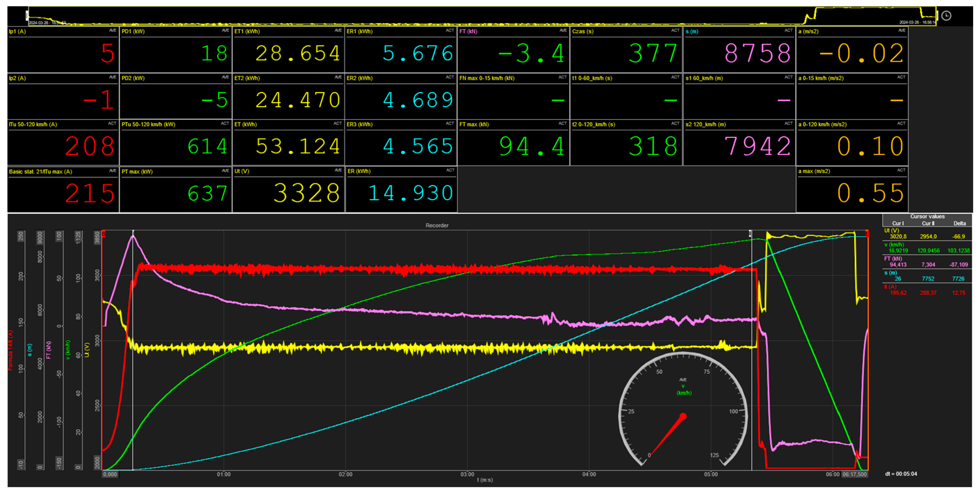
The test results are presented in Table 2 and Figure 4. The purpose of the measurements is to estimate the energy consumption that can be recovered during electrodynamic braking for a single cycle, consisting in accelerating a stopped vehicle to the maximum speed and stopping it using electrodynamic braking.
The total electrical energy ET was the energy consumed by the vehicle from the traction network ET and ER released during the recuperation process. Based on experimental measurements, the volume of energy that could be recovered in the electrodynamic braking process was estimated. In the case of the tested vehicle, regardless of the type of electric or diesel drive used, it was possible to recover approximately 15 kWh of the energy taken from the traction network in the electrodynamic braking process. Measurements carried out for a two-unit diesel–electric multiple unit according to the described methodology produced similar results. The energy recoverable through electrodynamic braking was 28.5%.

3.2. Development of Electrode Material from Starch

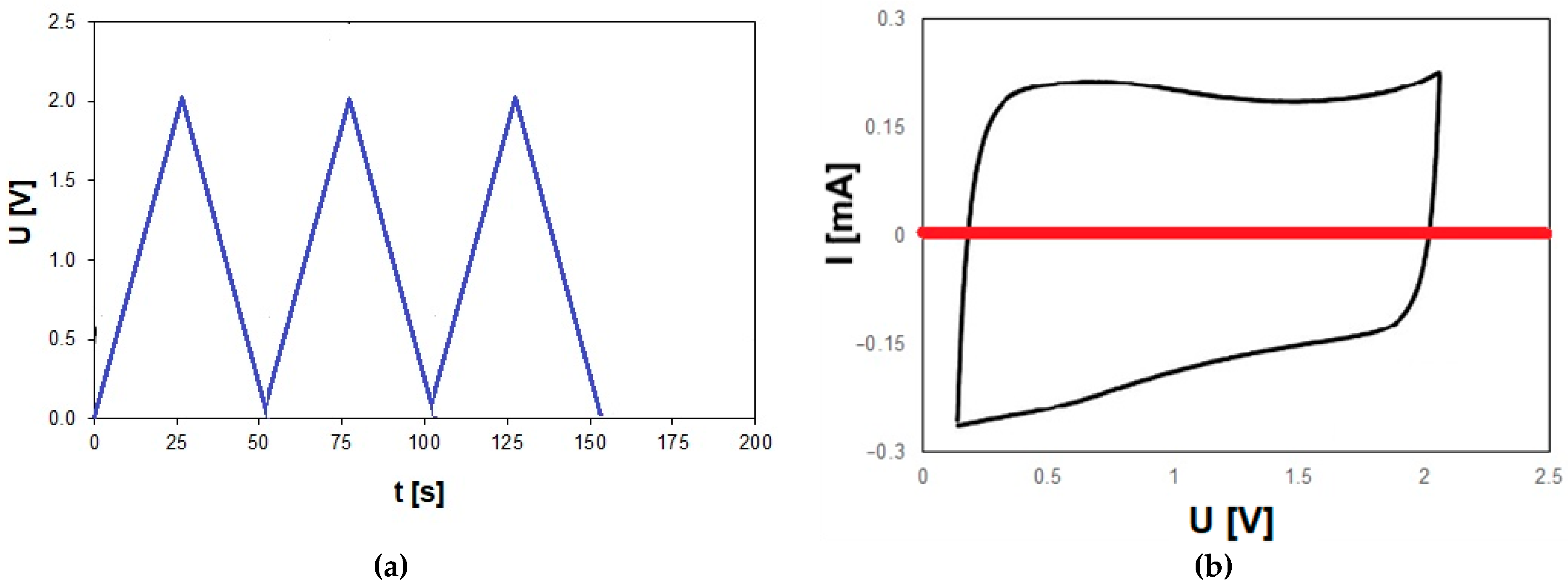
Devices featuring starch-based electrodes, much like their carbon–graphite counterparts, exhibit operational capabilities up to a maximum voltage of 2 V [38,39,40,41]. Notably, a distinct alteration in the cyclic voltammetry (CV) curves of supercapacitors employing starch-based electrodes becomes evident, clearly signifying an enhancement in charge propagation within each device following the introduction of acetonitrile into the electrolyte (Figure 5).
This observable change in the CV curves is indicative of an improved charge transfer process within these devices. Furthermore, the incorporation of ionic liquid leads to an augmentation in the capacity of these devices and a noticeable enhancement in their charge retention capabilities at higher potential cycling rates.
The obtained material has a capacity of up to 130 F/g. Activated carbons, especially commercial ones, are attractive electrode materials for EDLC supercapacitors due to economic reasons and the possibility of obtaining a highly developed internal surface with a controlled pore size distribution. Depending on the porous texture and chemical nature of the surface—factors influenced by the type of raw material and preparation conditions—the relative capacity of the electrical double layer of activated carbons varies widely, within the range of 15–50 μF/cm2. Assuming a theoretical mean level of 25 μF/cm2 and an internal surface area of 1000 m2/g, it should be possible to achieve a capacity of 250 F/g. In practice, however, much lower values are obtained because of the limited availability of the largely microporous carbon surface for the electrolyte.
The internal area determined by the gas sorption method is very different compared to the electrochemically reactive surface accessible to electrolyte ions. For aqueous electrolytes, it can be assumed that pores are greater than 0.5 nm, determined by the nitrogen sorption method, and should be electrochemically accessible. This is due to the similar average (thermodynamic) size of the nitrogen molecule at 77 K and the hydrated ions (e.g., H+, OH, and K+). For aprotic media, such as propylene carbonate, the dimensions of the solvated ions are much larger, e.g., ~2 nm for BF4 or ~5 nm for (C2H5)4N+, and the micropores do not contribute to the capacity of the bi-layer. Therefore, the type of electrolyte must be matched to the pore characteristics of the material (or vice versa).
In practice, the situation is more complicated. The porous texture of the material, in addition to the “molecular sieve” effect described above, affects the overall ionic conductivity of the system. The movement capacity of ions in the pores (electrochemically accessible) varies from their mobility in the electrolyte volume. The mobility of ions in narrow pores is problematic. The most significant improvements are observed in devices utilizing electrolytes derived from ionic liquids, which inherently possess the higher specific conductivity in their pure form.
Supercapacitors can be connected with other components in series or in parallel. At times, it proves beneficial to join multiple supercapacitors in parallel to create a functional unit, as illustrated in the diagram. In such scenarios, it is crucial to understand the equivalent capacity of the parallel arrangement. This discussion is going to delve into the analysis of parallel supercapacitor connections and explore potential applications for such configurations.
Electrical energy is stored in supercapacitors in the form of electrical charge. By paralleling multiple supercapacitors, the resultant circuit can store greater amount of energy [42,43,44,45], given that the equivalent capacitance is the sum of the individual capacitances of all involved capacitors. This principle finds application in various scenarios:
  • DC supplies may incorporate multiple parallel supercapacitors to enhance signal filtration and eliminate AC ripple. This method enables the utilization of smaller supercapacitors with superior ripple characteristics while achieving higher capacitance values.
  • Certain applications demand capacity rates surpassing those offered by commercially available supercapacitors. Supercapacitor banks address this need, such as those employed for power factor correction with inductive loads or energy storage in automotive applications like KERS (Kinetic Energy Recovery System) for regenerative braking.
When connecting supercapacitors in parallel, it must be taken into account that the maximum rated voltage of the parallel connection of supercapacitors is equal to the lowest rated voltage of all supercapacitors involved. Therefore, care must be taken to ensure system compatibility and security. To determine how many supercapacitors are needed to store a total energy of 15 kWh, we can follow these steps:
  • 1 kWh = 3600 kJ
  • Therefore, 15 kWh = 15 × 360,015 × 3600 kJ = 54,000 kJ = 54,000,000 J.
  • The energy stored in a supercapacitor is given by Equation (7), where E is the energy, C is the capacitance, and U is the voltage.
  • Given that the capacitance C is 130 F/g, we need to know the voltage U at which the supercapacitors operate.
  • The energy stored in one supercapacitor E = 1/2 × 130 F × U2; U = 1.8 V
  • Simplifying, E = 65 × 1.82 = 220.32 J/g.
  • To determine the number of supercapacitors needed, we carry out the following:
    • Total energy required = 54,000,000 J
    • Energy per supercapacitor = 65 × U2  J (assuming 1 g per capacitor)
    • Number of supercapacitors N:
N = 54,000,000 65   U 2   = 54,000,000 65   1.8 2 = 256,041
Thus, approximately 256,410 supercapacitors, each with a capacity of 130 F/g at 1.8 V, are needed to store 15 kWh of energy.
  • To determine the total mass of supercapacitors, we consider the following:
    • Total energy = 54,000,000 J
    • Energy stored per gram = 220.32 J/g
    • Total mass M:
M = 54,000,000   J 220.32 J g M = 245,098.04   g = 245.1   kg
The total mass of the supercapacitors required to store 15 kWh of energy is approximately 245.1 kg.

4. Conclusions

This study presents a comprehensive exploration of energy storage using starch-derived carbon materials for supercapacitors, along with an analysis of energy recovery systems in railway vehicles and their potential applications. Starch carbonization provides an economical and efficient route to the production of carbon materials with favourable properties for energy storage applications.
The resulting materials exhibit capacitances of up to 130 F/g, making them competitive for use in supercapacitors. Starch-derived carbon materials show significant improvements in charge transfer and retention when combined with ionic liquids and optimized electrolytes. This indicates the importance of tailoring the electrolytes to the porous structure of the material. The internal surface area and pore size distribution play a key role in determining the specific capacitance, with changes in material processing and electrolyte selection required to maximize performance.
Measurements from electrodynamic braking tests in diesel–electric trains reveal that about 28.8% of the consumed energy can be recovered during braking. This highlights the potential of regenerative systems to improve energy efficiency. Supercapacitors are a viable solution for storing this recovered energy due to their rapid charge and discharge capabilities and long lifetime. This study found that approximately 256,041 supercapacitors (each with a capacitance of 130 F/g at 1.8 V) would be required to store 15 kWh of energy. This would correspond to a total mass of 245.1 kg. Parallel connections of supercapacitors enable capacitance aggregation, enabling practical applications such as DC signal filtering, power factor correction, and kinetic energy recovery systems.
While starch-derived materials are promising, the discrepancy between theoretical and practical capacitance values highlights the need for further research into optimizing pore accessibility and electrolyte compatibility. Further research should focus on increasing the energy density of supercapacitors to reduce the total mass and volume required for large-scale energy storage applications.
This study highlights the feasibility of integrating supercapacitor technologies into renewable energy systems and regenerative braking applications. Future work should investigate the scaling of these technologies and the development of hybrid systems combining supercapacitors with other energy storage technologies to address diverse application needs.

Author Contributions

Conceptualization, K.W., B.K., Ł.R. and N.S.; methodology, K.W. and B.K.; software, K.W. and B.K.; validation, formal analysis, K.W., B.K., Ł.R. and N.S.; investigation, B.K., J.S. and P.P.; data curation, K.W., B.K. and Ł.R.; writing—original draft preparation, K.W., B.K. and Ł.R.; writing—review and editing, N.S., J.S. and P.P.; visualization, K.W. and B.K.; supervision, Ł.R. and N.S.; project administration, K.W., B.K. and Ł.R.; funding acquisition, Ł.R. and N.S. All authors have read and agreed to the published version of the manuscript.

Funding

The study presented in this article was performed within statutory research (No. 0415/SBAD/0351).

Data Availability Statement

The original contributions presented in the study are included in the article. Further inquiries can be directed to the corresponding authors.

Conflicts of Interest

The authors declare no conflict of interest.

References

  1. Andrych-Zalewska, M.; Chłopek, Z.; Merkisz, J.; Pielecha, J. Research on the Results of the WLTP Procedure for a Passenger Vehicle. Maint. Reliab./Eksploat. I Niezawodn. 2024, 26, 1–15. [Google Scholar] [CrossRef]
  2. Rymaniak, Ł.; Merkisz, J.; Szymlet, N.; Kamińska, M.; Weymann, S. Use of Emission Indicators Related to CO2 Emissions in the Ecological Assessment of an Agricultural Tractor. Eksploat. I Niezawodn. 2021, 23, 605–611. [Google Scholar] [CrossRef]
  3. Ziółkowski, A.; Fuć, P.; Jagielski, A.; Bednarek, M.; Konieczka, S. Comparison of the Energy Consumption and Exhaust Emissions between Hybrid and Conventional Vehicles, as Well as Electric Vehicles Fitted with a Range Extender. Energies 2023, 16, 4669. [Google Scholar] [CrossRef]
  4. Pielecha, I.; PIelecha, J. Simulation Analysis of Electric Vehicles Energy Consumption in Driving Tests. Eksploat. I Niezawodn. 2020, 22, 130–137. [Google Scholar] [CrossRef]
  5. Pielecha, I.; Szwajca, F. Cooperation of a PEM Fuel Cell and a NiMH Battery at Various States of Its Charge in a FCHEV Drive. Eksploat. I Niezawodn. 2021, 23, 468–475. [Google Scholar] [CrossRef]
  6. Kęska, A. The Actual Toxicity of Engine Exhaust Gases Emitted from Vehicles: The Development and Perspectives of Biological and Chemical Measurement Methods. ACS Omega 2023, 8, 24718–24726. [Google Scholar] [CrossRef]
  7. Merkisz, J.; Pielecha, J. Nanoparticle Emissions from Combustion Engines; Springer: Berlin/Heidelberg, Germany, 2015; ISBN 3-319-15928-3. [Google Scholar]
  8. Ziółkowski, A.; Fuć, P.; Lijewski, P.; Jagielski, A.; Bednarek, M.; Kusiak, W. Analysis of Exhaust Emissions from Heavy-Duty Vehicles on Different Applications. Energies 2022, 15, 7886. [Google Scholar] [CrossRef]
  9. Conzen, J.; Lakshmipathy, S.; Kapahi, A.; Kraft, S.; DiDomizio, M. Lithium Ion Battery Energy Storage Systems (BESS) Hazards. J. Loss Prev. Process Ind. 2023, 81, 104932. [Google Scholar] [CrossRef]
  10. Gao, Z.; Zhang, Y.; Song, N.; Li, X. Biomass-Derived Renewable Carbon Materials for Electrochemical Energy Storage. Mater. Res. Lett. 2017, 5, 69–88. [Google Scholar] [CrossRef]
  11. Kim, B.K.; Sy, S.; Yu, A.; Zhang, J. Electrochemical Supercapacitors for Energy Storage and Conversion. Handb. Clean Energy Syst. 2015, 1–25. [Google Scholar] [CrossRef]
  12. Ranaweera, C.; Kahol, P.; Ghimire, M.; Mishra, S.; Gupta, R.K. Orange-Peel-Derived Carbon: Designing Sustainable and High-Performance Supercapacitor Electrodes. C 2017, 3, 25. [Google Scholar] [CrossRef]
  13. Qi, M.; Liu, Y.; Landon, R.S.; Liu, Y.; Moon, I. Assessing and Mitigating Potential Hazards of Emerging Grid-Scale Electrical Energy Storage Systems. Process Saf. Environ. Prot. 2021, 149, 994–1016. [Google Scholar] [CrossRef]
  14. Rosewater, D.; Williams, A. Analyzing System Safety in Lithium-Ion Grid Energy Storage. J. Power Sources 2015, 300, 460–471. [Google Scholar] [CrossRef]
  15. Wu, Y.; Zhang, T. Risk Assessment of Offshore Wave-Wind-Solar-Compressed Air Energy Storage Power Plant through Fuzzy Comprehensive Evaluation Model. Energy 2021, 223, 120057. [Google Scholar] [CrossRef]
  16. Sawczuk, W.; Jüngst, M.; Ulbrich, D.; Kowalczyk, J. Modeling the Depth of Surface Cracks in Brake Disc. Materials 2021, 14, 3890. [Google Scholar] [CrossRef]
  17. Sawczuk, W.; Merkisz-Guranowska, A.; Ulbrich, D.; Kowalczyk, J.; Cañás, A.-M.R. Investigation and Modelling of the Weight Wear of Friction Pads of a Railway Disc Brake. Materials 2022, 15, 6312. [Google Scholar] [CrossRef]
  18. Dai, H. Carbon Nanotubes: Opportunities and Challenges. Surf. Sci. 2002, 500, 218–241. [Google Scholar] [CrossRef]
  19. Frackowiak, E.; Gautier, S.; Gaucher, H.; Bonnamy, S.; Beguin, F. Electrochemical Storage of Lithium in Multiwalled Carbon Nanotubes. Carbon 1999, 37, 61–69. [Google Scholar] [CrossRef]
  20. Wang, X.; Sun, L.; Susantyoko, R.A.; Fan, Y.; Zhang, Q. Ultrahigh Volumetric Capacity Lithium Ion Battery Anodes with CNT–Si Film. Nano Energy 2014, 8, 71–77. [Google Scholar] [CrossRef]
  21. Wong, S.I.; Sunarso, J.; Wong, B.T.; Lin, H.; Yu, A.; Jia, B. Towards Enhanced Energy Density of Graphene-Based Supercapacitors: Current Status, Approaches, and Future Directions. J. Power Sources 2018, 396, 182–206. [Google Scholar] [CrossRef]
  22. Ke, Q.; Wang, J. Graphene-Based Materials for Supercapacitor Electrodes—A Review. J. Mater. 2016, 2, 37–54. [Google Scholar] [CrossRef]
  23. Chen, C.-M.; Zhang, Q.; Yang, M.-G.; Huang, C.-H.; Yang, Y.-G.; Wang, M.-Z. Structural Evolution during Annealing of Thermally Reduced Graphene Nanosheets for Application in Supercapacitors. Carbon 2012, 50, 3572–3584. [Google Scholar] [CrossRef]
  24. Fan, Z.; Zhao, Q.; Li, T.; Yan, J.; Ren, Y.; Feng, J.; Wei, T. Easy Synthesis of Porous Graphene Nanosheets and Their Use in Supercapacitors. Carbon 2012, 50, 1699–1703. [Google Scholar] [CrossRef]
  25. Li, C.; Zhang, X.; Wang, K.; Zhang, H.; Sun, X.; Ma, Y. Three Dimensional Graphene Networks for Supercapacitor Electrode Materials. New Carbon Mater. 2015, 30, 193–206. [Google Scholar] [CrossRef]
  26. Rudge, A.; Davey, J.; Raistrick, I.; Gottesfeld, S.; Ferraris, J.P. Conducting Polymers as Active Materials in Electrochemical Capacitors. J. Power Sources 1994, 47, 89–107. [Google Scholar] [CrossRef]
  27. Pigłowska, M.; Kurc, B.; Galiński, M.; Fuć, P.; Kamińska, M.; Szymlet, N.; Daszkiewicz, P. Challenges for Safe Electrolytes Applied in Lithium-Ion Cells—A Review. Materials 2021, 14, 6783. [Google Scholar] [CrossRef]
  28. Kurc, B.; Pigłowska, M.; Rymaniak, Ł.; Fuć, P. Modern Nanocomposites and Hybrids as Electrode Materials Used in Energy Carriers. Nanomaterials 2021, 11, 538. [Google Scholar] [CrossRef]
  29. Zhang, J.; Gu, M.; Chen, X. Supercapacitors for Renewable Energy Applications: A Review. Micro Nano Eng. 2023, 21, 100229. [Google Scholar] [CrossRef]
  30. Gifford, P.; Adams, J.; Corrigan, D.; Venkatesan, S. Development of Advanced Nickel/Metal Hydride Batteries for Electric and Hybrid Vehicles. J. Power Sources 1999, 80, 157–163. [Google Scholar] [CrossRef]
  31. Kouchachvili, L.; Yaïci, W.; Entchev, E. Hybrid Battery/Supercapacitor Energy Storage System for the Electric Vehicles. J. Power Sources 2018, 374, 237–248. [Google Scholar] [CrossRef]
  32. Muhiuddin, M.; Khan, A.Z.; Devi, N.A.; Bharadishettar, N.; Meti, S.; Siddique, A.B.; Bhat, K.U.; Akhtar, W.; Rahman, M.R. Cost Effective Synthesis of Sulfur and Nitrogen Co-Doped Graphene Aerogel and Application in Binder Free Supercapacitor. J. Appl. Phys. 2024, 136, 034901. [Google Scholar] [CrossRef]
  33. Barić, T.; Glavaš, H.; Barukčić, M. Impact of Balance Resistor Uncertainty on Voltages across Supercapacitors. J. Energy Storage 2019, 22, 131–136. [Google Scholar] [CrossRef]
  34. Xiong, G.; Kundu, A.; Fisher, T.S. Influence of Temperature on Supercapacitor Performance. In Thermal Effects in Supercapacitors; Xiong, G., Kundu, A., Fisher, T.S., Eds.; Springer International Publishing: Cham, Switzerland, 2015; pp. 71–114. ISBN 978-3-319-20242-6. [Google Scholar]
  35. Zou, Z.; Cao, J.; Cao, B.; Chen, W. Evaluation Strategy of Regenerative Braking Energy for Supercapacitor Vehicle. ISA Trans. 2015, 55, 234–240. [Google Scholar] [CrossRef] [PubMed]
  36. Adeyemo, A.A.; Alves, E.; Marra, F.; Brandao, D.; Tedeschi, E. Suitability Assessment of High-Power Energy Storage Technologies for Offshore Oil and Gas Platforms: A Life Cycle Cost Perspective. J. Energy Storage 2023, 61, 106643. [Google Scholar] [CrossRef]
  37. Kurc, B.; Lijewski, P.; Rymaniak, Ł.; Fuć, P.; Pigłowska, M.; Urbaniak, R.; Ciupek, B. High-Energy Solid Fuel Obtained from Carbonized Rice Starch. Energies 2020, 13, 4096. [Google Scholar] [CrossRef]
  38. Liu, Y.; Chen, J.; Cui, B.; Yin, P.; Zhang, C. Design and Preparation of Biomass-Derived Carbon Materials for Supercapacitors: A Review. C 2018, 4, 53. [Google Scholar] [CrossRef]
  39. Wang, X.; Xie, X.; Xie, K.; Liu, Q.; Li, Y.; Tan, X.; Dong, H.; Li, X.; Dong, Z.; Xia, Q. Chitin and Cuticle Proteins Form the Cuticular Layer in the Spinning Duct of Silkworm. Acta Biomater. 2022, 145, 260–271. [Google Scholar] [CrossRef]
  40. Yang, X.; Fei, B.; Ma, J.; Liu, X.; Yang, S.; Tian, G.; Jiang, Z. Porous Nanoplatelets Wrapped Carbon Aerogels by Pyrolysis of Regenerated Bamboo Cellulose Aerogels as Supercapacitor Electrodes. Carbohydr. Polym. 2018, 180, 385–392. [Google Scholar] [CrossRef]
  41. Zhuo, H.; Hu, Y.; Chen, Z.; Zhong, L. Cellulose Carbon Aerogel/PPy Composites for High-Performance Supercapacitor. Carbohydr. Polym. 2019, 215, 322–329. [Google Scholar] [CrossRef]
  42. Cáceres, G.; Fullenkamp, K.; Montané, M.; Naplocha, K.; Dmitruk, A. Encapsulated Nitrates Phase Change Material Selection for Use as Thermal Storage and Heat Transfer Materials at High Temperature in Concentrated Solar Power Plants. Energies 2017, 10, 1318. [Google Scholar] [CrossRef]
  43. Nazir, H.; Batool, M.; Osorio, F.J.B.; Isaza-Ruiz, M.; Xu, X.; Vignarooban, K.; Phelan, P.; Kannan, A.M. Recent Developments in Phase Change Materials for Energy Storage Applications: A Review. Int. J. Heat Mass Transf. 2019, 129, 491–523. [Google Scholar] [CrossRef]
  44. Wang, Z.; Sun, S.; Lin, X.; Liu, C.; Tong, N.; Sui, Q.; Li, Z. A Remote Integrated Energy System Based on Cogeneration of a Concentrating Solar Power Plant and Buildings with Phase Change Materials. Energy Convers. Manag. 2019, 187, 472–485. [Google Scholar] [CrossRef]
  45. Zhao, B.; Cheng, M.; Liu, C.; Dai, Z. Thermal Performance and Cost Analysis of a Multi-Layered Solid-PCM Thermocline Thermal Energy Storage for CSP Tower Plants. Appl. Energy 2016, 178, 784–799. [Google Scholar] [CrossRef]
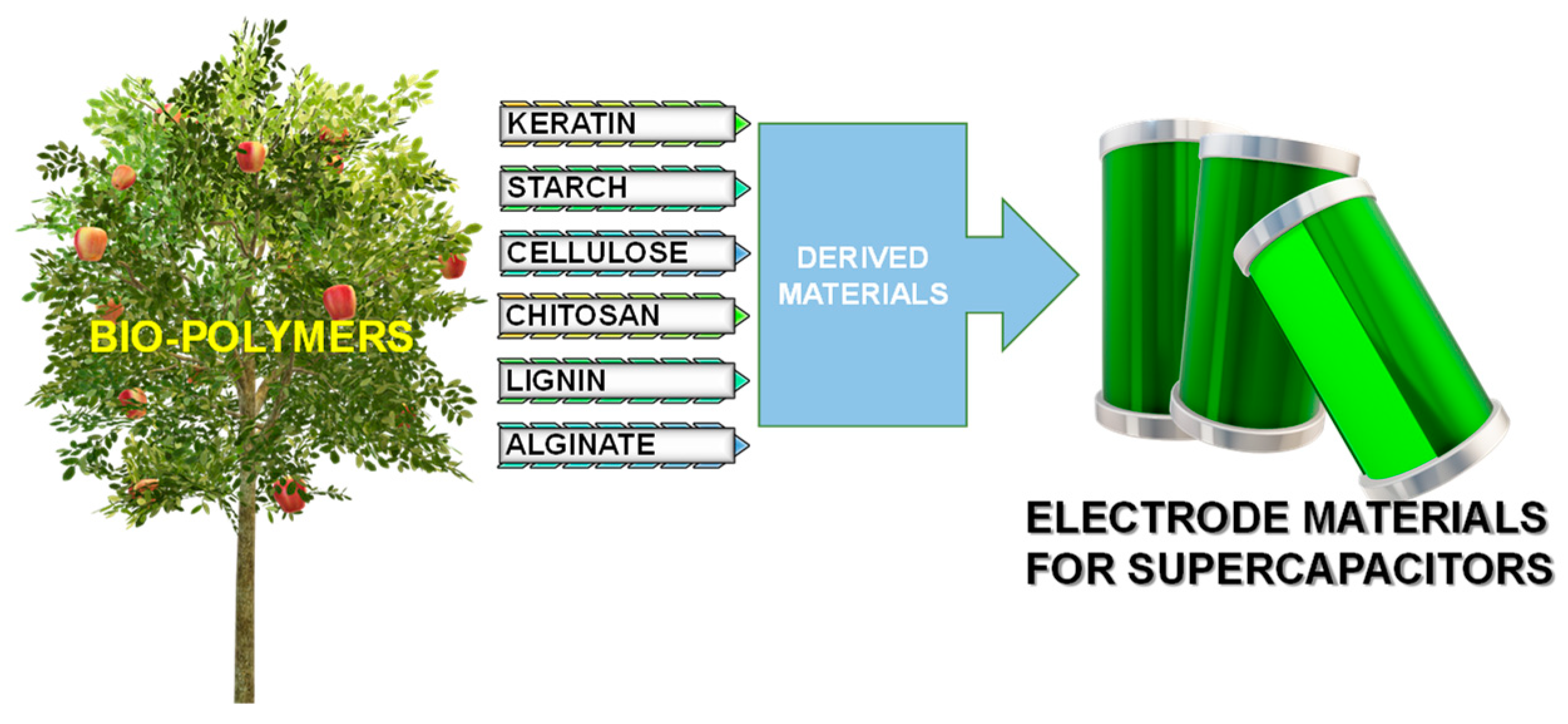
Figure 1. Application directions for biomass in a broad sense.
Energies 17 05904 g001
Figure 2. SEM of starch: (a) before, (b) after carbonization.
Energies 17 05904 g002
Figure 3. Three car body diesel–electric multiple unit.
Energies 17 05904 g003
Figure 4. Measurement results for sample.
Energies 17 05904 g004
Figure 5. Electrochemical characterization of the supercapacitors. (a) Galvanostatic charging and discharging curves of the supercapacitor measured at current density from 100 mA/g. (b) Cyclic voltammogram curves measured at a scan rate of 100 mV/s (c). (d) SEM images of carbon materials.
Energies 17 05904 g005aEnergies 17 05904 g005b
Table 1. Technical characteristics selected for testing.
Technical DataValue
Track width [mm]1435
Overall length with bumpers [mm]78,600
Top speed—electric drive [km/h]160
Top speed—diesel drive [km/h]120
Axle arrangement2’Bo’ + Bo’2’+ Bo’2’
Traction motor power [kW]6 × 300
Total power of combustion engine power [kW]900
Braking resistors maximum power (RH1, RH2, RH3) [kW]3 × 1000
Number of seats for passengers156
Mass of vehicle [kg]171,332
Table 2. Traction parameters for load condition.
No.Specific ParametersTime (t) and Distance (s)Total
Distance
Energy Consumed by the Vehicle ET and Returned to the Braking Resistors
ER1 + ER3 + ER3 = ER
Brake Setting “P”—Passanger
60 km/h120 km/h
ITu(1)PTmax(2)PTu(3)FNmax(4)amax(5)av(6)av(7)t1s1t2s2sETER1ER2ER3ERET – ERER/ET
AkWkWkNm/s2m/s2m/s2smsmmkWhkWhkWhkWhkWhkWh%
1208636612960.560.300.11545133067 5188 52250.725.834.894.6315.3535.3730.27
2207636611950.550.280.10555133187 8398 77652.295.744.834.6415.2137.0729.09
3208646616960.560.300.10565283248 1208 93853.955.704.804.5315.0238.9327.84
4208640615940.550.290.11565213137 8698 66951.915.814.874.5915.2736.6429.41
5208642613920.530.300.10575633197 7908 73153.665.664.904.6415.2038.4728.32
6208637614940.550.300.10575503187 7428 75853.124.694.574.5713.8239.3126.01
7208640613950.550.300.11565333177 7438 74752.795.654.824.5715.0337.7528.48
Av.
values
208640613950.550.300.10565323167 8038 73452.635.584.814.6014.9837.6528.49
(1) Average current during start-up (for speed 50 ÷ 120 km/h); (2) the maximum value of the power consumed by the vehicle during starting (for speed 0 ÷ 120 km/h); (3) average power value during start-up (for speed 50 ÷ 120 km/h); (4) maximum value of the driving force during the start-up (for speed 0 ÷ 120 km/h); (5) maximum acceleration value during start-up (for speed 0 ÷ 120 km/h); (6) average acceleration value during start-up (for speed 0 ÷ 15 km/h); (7) average acceleration value during start-up (for speed 0 ÷ 120 km/h).
Disclaimer/Publisher’s Note: The statements, opinions and data contained in all publications are solely those of the individual author(s) and contributor(s) and not of MDPI and/or the editor(s). MDPI and/or the editor(s) disclaim responsibility for any injury to people or property resulting from any ideas, methods, instructions or products referred to in the content.