Review

The Generation Methods and Applications of Cavitating Jet by Using Bubble Collapse Energy

1
Hubei Key Laboratory of Waterjet Theory and New Technology, Wuhan University, Wuhan 430072, China
2
School of Power and Mechanical Engineering, Wuhan University, Wuhan 430072, China
*
Author to whom correspondence should be addressed.
Energies 2024, 17(23), 5902; https://doi.org/10.3390/en17235902
Submission received: 30 October 2024 / Revised: 15 November 2024 / Accepted: 20 November 2024 / Published: 25 November 2024
(This article belongs to the Section K: State-of-the-Art Energy Related Technologies)

Abstract

:
Cavitation is a dynamic process characterized by the formation, growth, and collapse of vapor or gas vacuoles in liquids or at the liquid–solid interface, initiated by a local pressure drop. This phenomenon releases concentrated energy through microjet impacts and shock waves, leading to a violent exchange of energy with the surrounding environment. While cavitation is often perceived as detrimental, certain aspects can be harnessed for practical applications. Relevant studies have shown that cavitating jets provide high operating efficiencies, reduce energy consumption per unit, and have the potential for waste treatment. This paper presents three types of cavitating jets: central body cavitation, oscillatory cavitation, and shear cavitation. Additionally, the formation process of a cavitating jet and the effects of various factors on jet performance are discussed. Following an in-depth examination of the cavitation phenomena, subsequent chapters explore the applications of cavitating jets in material surface enhancement, cleaning, and energy exploration. Furthermore, recommendations for future research on cavitating jets are provided. This paper provides a comprehensive literature review on cavitating jets.

1. Introduction

In 1897, S. W. Barnaby and C. A. Parsons were the first to recognize the hazards of bubble collapse in water from steam turbine propellers [1], introducing the concept of “cavitation”. While cavitation can significantly damage hydraulic machinery, reduce efficiency, strip material, and generate vibration and noise, it also has useful applications. As research progressed, Johanson and Kohl et al. [2] introduced cavitation to water jet technology, leading to the development of cavitating jets. Studies have demonstrated that cavitating jets offer advantages such as high operational efficiency, low specific energy consumption, and cleaner processes. Researchers are currently investigating methods to improve the efficiency and practicality of cavitating jets while expanding their applications across various fields to fully exploit their potential.
A cavitating jet consists of artificially generated bubbles that enhance the jet’s impact capability by harnessing the significant energy released during bubble collapse. The fundamental principle involves using nozzles with specialized structures or external factors to induce cavitation in the jet. As the jet progresses, these bubbles develop, grow, and eventually collapse. During collapse, the energy released becomes highly concentrated, resulting in extremely high localized impact pressure and stress concentration, which can rapidly damage the surface of the affected object. Johnson et al. [2] and Conn et al. [3] introduced the concept of the cavitating jet and demonstrated that, under equivalent conditions, the impact pressure of a cavitating jet is 8.6 to 124 times greater than that of a continuous jet.
This paper discusses three types of cavitating jet and their generation methods: central body cavitation, oscillatory cavitation, and shear cavitation [4,5]. In 1968, Johnson et al. [2] developed the rotary vane and central body type nozzles, elucidating the principle of cavitation. When water passes through the specialized nozzle structure, the local pressure of the jet is reduced, altering the flow conditions and inducing cavitation. In the early 1980s, Johnson et al. [6,7] introduced the concept of self-excited cavitation water jets based on hydroacoustic principles, subsequently constructing acoustic resonance self-excited cavitating jets. The two typical structures are the organ pipe nozzle and the Helmholtz oscillatory chamber nozzle. Lichtarowicz’s research [8] suggests that submerged jets can achieve improved cavitation effects through shear effects. Following this, many researchers have investigated the jet performance of various nozzle types under submerged conditions. Tavoularis et al. [9] and Soyama et al. [10,11,12] progressively employed annular sleeves around nozzles or low-pressure, low-speed circulation techniques (i.e., coaxial overlapping nozzles) to create artificial submerged conditions. This boundary induces a shearing effect, leading to cavitation and expanding the application range of the cavitating jet. Continuous research has contributed to the widespread applications of cavitating jets in cleaning, surface enhancement, cutting, energy exploration, etc.

2. Generation Methods of Cavitating Jets

2.1. Cavitation Formation, Growth and Collapse

A cavitating jet is defined as a jet in which cavitation bubbles are generated either naturally or artificially within the jet stream. Cavitation bubbles are typically generated through submersion, employing various methods to create a region within the fluid where the pressure is lower than the local saturated vapor pressure, thus resulting in bubble formation [13]. These bubbles become entrained in the jet’s further growth and expansion until they approach the surface to be cleaned or cut, influenced by the stagnation pressure caused by their rupture. During this rupture process, extremely high transient pressures and micro-jets are generated; the potential energy stored in the bubbles is instantaneously converted into the kinetic energy of the surrounding liquid, which is violently exchanged with the environment. The order of magnitude of the generated shock pressure is greater than 1 GPa and the microjet can reach very high local velocities (several 100 m/s) [14,15,16,17,18,19,20,21,22], and some other effects such as luminescence may occur during the process [23]. Due to the difficulty of directly measuring the pressure peak caused by bubble implosion, the energy release mechanism of cavitating jet is now often clarified indirectly by means of vibration measurements or by evaluating the number and shape of craters caused by cavitating bubbles on the surface of the material [24,25]. Furthermore, the process of bubble rupture has been shown to be accompanied by the formation of shock waves [26,27,28,29], as illustrated in Figure 1. These shock waves are generated at the moment of cavitation cloud collapse, and their formation range closely aligns with the erosion area of the cavitating jet on the wall material, indicating that shock wave formation plays a critical role in cavitation erosion.
Countless bubbles form cavitation clouds, and the formation, growth and collapse of cavitation clouds is a periodic process, which has been verified in previous studies [30,31,32,33,34,35,36]. The shape of the cavitation cloud is often irregular and asymmetric. Figure 2 demonstrates the full-cycle process of cavitation cloud development through experiments and numerical simulations, where the dashed line represents the cavitation cloud front. Before the cavitation cloud collapses, there is a shedding process, such as the contraction of cavitation cloud D at the nozzle in Figure 2, which is attributed to the ‘re-entrant motion’ of the cavitation cloud [31,37]. The development of the cavitation cloud is influenced by the jet core [38,39,40] and the vortex [41,42,43]. During the initial phase of cavitation cloud formation, its volume is sustained by the associated vortex structure. The shedding of the cavitation cloud correlates with the instability of the jet core, while the jet core’s kinetic energy is expended to preserve the cavitation cloud’s structure. Currently, there are two primary methods to form a cavitating jet: utilizing the nozzle’s own structure and applying external excitation. According to the mechanism of occurrence, cavitation can be classified into center body cavitation, oscillatory cavitation, shear cavitation, ultrasonic cavitation and laser-induced cavitation, etc. Table 1 gives an overview of the features and the scope of application of various types of cavitation.

2.2. Central Body Cavitation

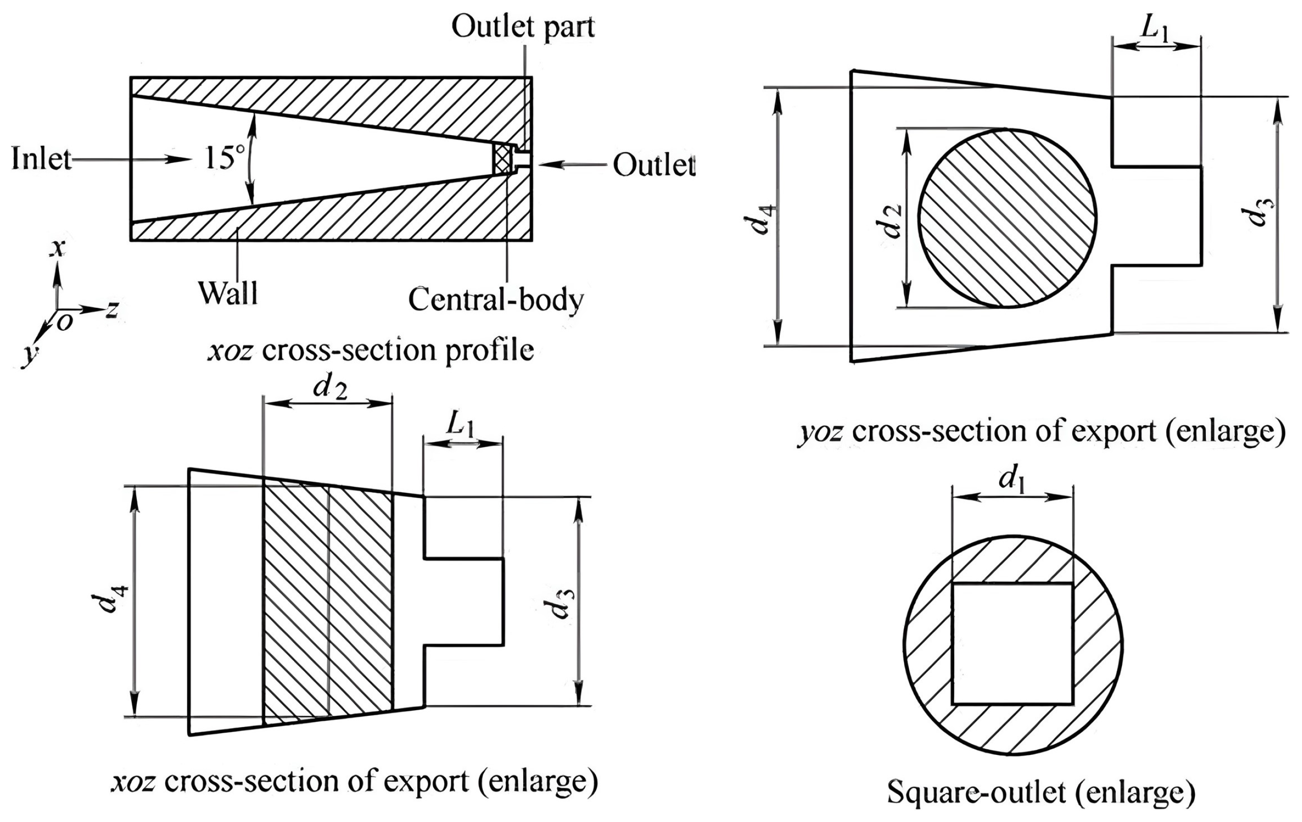
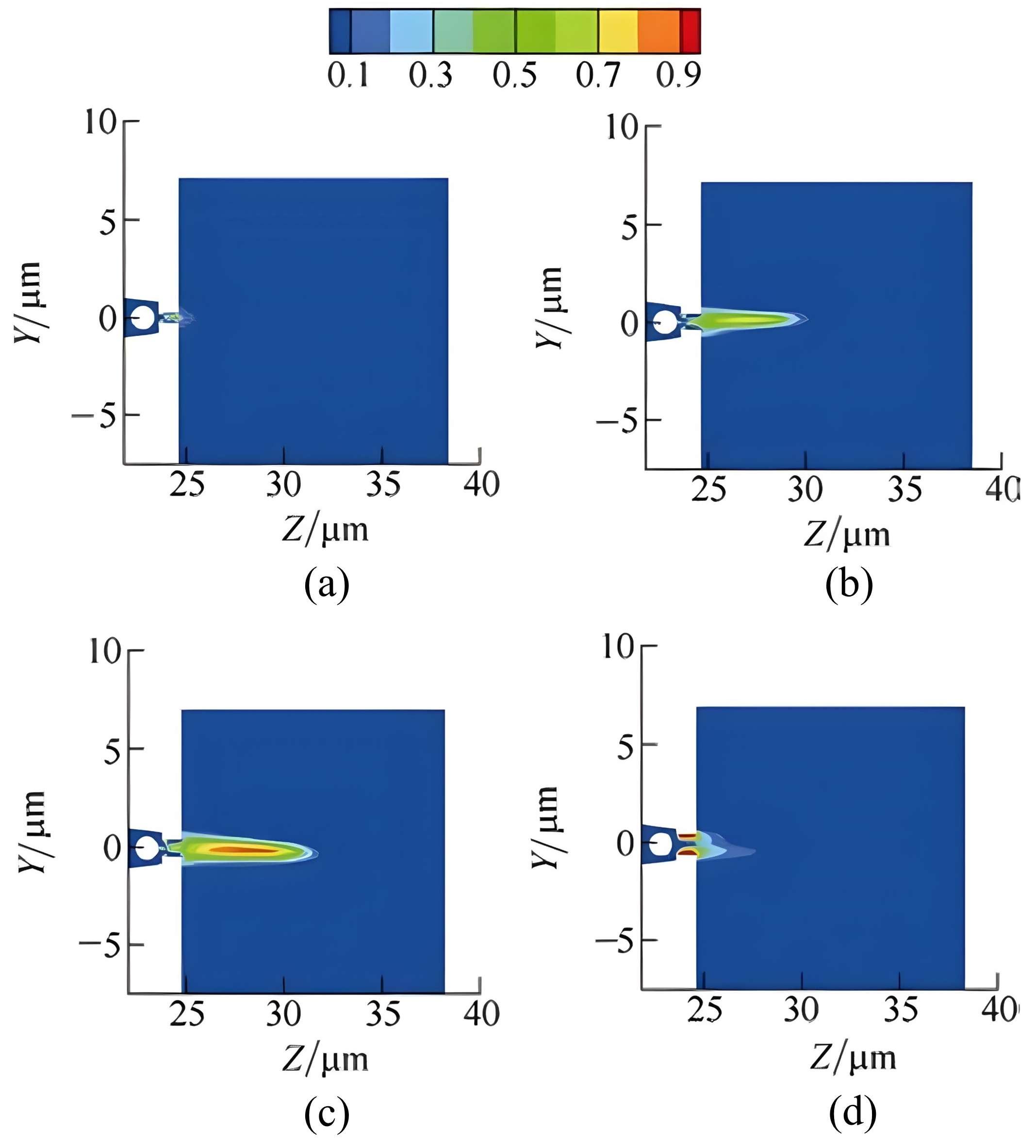
The typical cavitation nozzle is based on the Kármán vortex street, a fluid mechanics phenomenon. Specifically, a central body is incorporated into the nozzle to induce circumfluence. The structure of the central body nozzle is illustrated in Figure 3. As the fluid flows around the central body, liquid separation occurs, creating a wake filled with vortices downstream of the nozzle exit. Cavities develop within the center of the vortex, and the volume fraction of bubbles in the central body nozzle is depicted in Figure 4. Within a certain range, vacuoles form and grow. The central body nozzle is the primary component responsible for generating bypass-type cavitation. Both the constricted design of the nozzle and the tail of the central body contribute to cavitation generation, although the effect is more pronounced near the tail of the central body [52].
According to this principle, many studies have been conducted. Kang et al. [44] set the center body with the axis direction perpendicular to the direction of the jet within the nozzle flow channel, constituting an embedded center body nozzle. Under different relative diameter conditions, the cavitation water jet nozzle embedded in the center body was experimentally studied and it was found that the cavitation effect was related to the relative diameter of the center body, and as the relative diameter increased, the degree of cavitation became higher. Deng et al. [53] combined the shaped central body with a conical nozzle for numerical study and established three central body nozzle models containing a flat-headed column, a 90° conical column and a hemispherical column. The research result is shown in Table 2; conical nozzle designs tend to provide higher jet velocity and stability, making them ideal for applications requiring sustained cavitation effects. In contrast, flat-headed designs achieve higher cavitation intensity but suffer from reduced stability, indicating their suitability for applications where peak intensity is prioritized over prolonged jet stability. Liu et al. [45] found that the center body nozzles with diffusion angles induced cavitation significantly better than the center body nozzles without diffusion angles at a pressure inlet of 15 MPa, and the center body nozzles induced cavitation best when the diffusion angle was 15°. Yang et al. [54] proposed the idea of combining a central body nozzle with a shaped nozzle to produce a better cavitating jet effect and found that the cavitating jet effect is better in the flow field generated by a central body nozzle with a shaped outlet, where the air bubble phase extends over a longer distance. It can be presumed that the center body-shaped nozzle can increase the striking target distance of the cavitating jet [54].
Figure 3. Structure diagram of center body nozzle [55].
Energies 17 05902 g003
Figure 4. Bubble volume fraction of central-body nozzle with different contraction degrees [55]. (a) A = 0.12; (b) A = 0.32; (c) A = 0.39; (d) A = 0.60.
Energies 17 05902 g004
Some studies have indicated that the outreach central body nozzle can effectively mitigate the limitations of conventional cavitating jets at short distances [52]. Yang et al. [55] investigated a novel type of central body nozzle (Figure 3) and analyzed the impact of nozzle configuration on jet performance. The results demonstrate that when the relative diameter of the central body remains constant, there is an optimal reduction in the nozzle outlet size that promotes strong cavitation within the jet. Additionally, the relative diameter of the central body influences the jet profile. With a relatively large central body, most bubbles settle in the jet core; conversely, a smaller relative diameter leads to bubble concentration at the interface between the jet and the surrounding fluid. Furthermore, a shorter outlet section allows the cavitation zone to extend further in both axial and radial directions.
In recent studies on central body cavitation, researchers have investigated the effects of various central body geometries and configurations, highlighting differences in cavitation intensity and jet stability. Researchers have increasingly focused on enhancing cavitation initiation at lower pressures, reflecting the widespread interest in improving energy efficiency. However, center body cavitation is still limited by its effective range, particularly over short distances, suggesting that future research directions could explore ways to extend cavitation stability without compromising efficiency.

2.3. Oscillatory Cavitation

The oscillating cavitating jet is a novel high-efficiency jet developed in the early 1980s [56,57]. The destructive potential of the cavitating jet is primarily determined by the initial collapse of the bubble, followed by a rapid decrease in collapse intensity. The self-excited effect significantly enhances cavitation intensity by increasing collapse pressure and prolonging action duration [58]. Consequently, among various nozzles designed to improve cavitation intensity, self-excited nozzles—such as organ-pipe and Helmholtz nozzles—are widely utilized. These nozzles acoustically stimulate the jet, resulting in the periodic release of large vortex structures and cavitation clouds. This mechanism significantly increases cavitation intensity, particularly under elevated submersion conditions [59]. Furthermore, self-excited pulsed cavitating jet nozzles can convert continuous energy into pulsed energy through energy storage and release phases, resulting in an instantaneous peak force of the pulsed jet that exceeds that of the continuous jet. The maximum striking force is reported to be 1.6 to 1.7 times greater than that of the continuous cylindrical jet [60].

2.3.1. Helmholtz Type Self-Excited Cavitating Jet

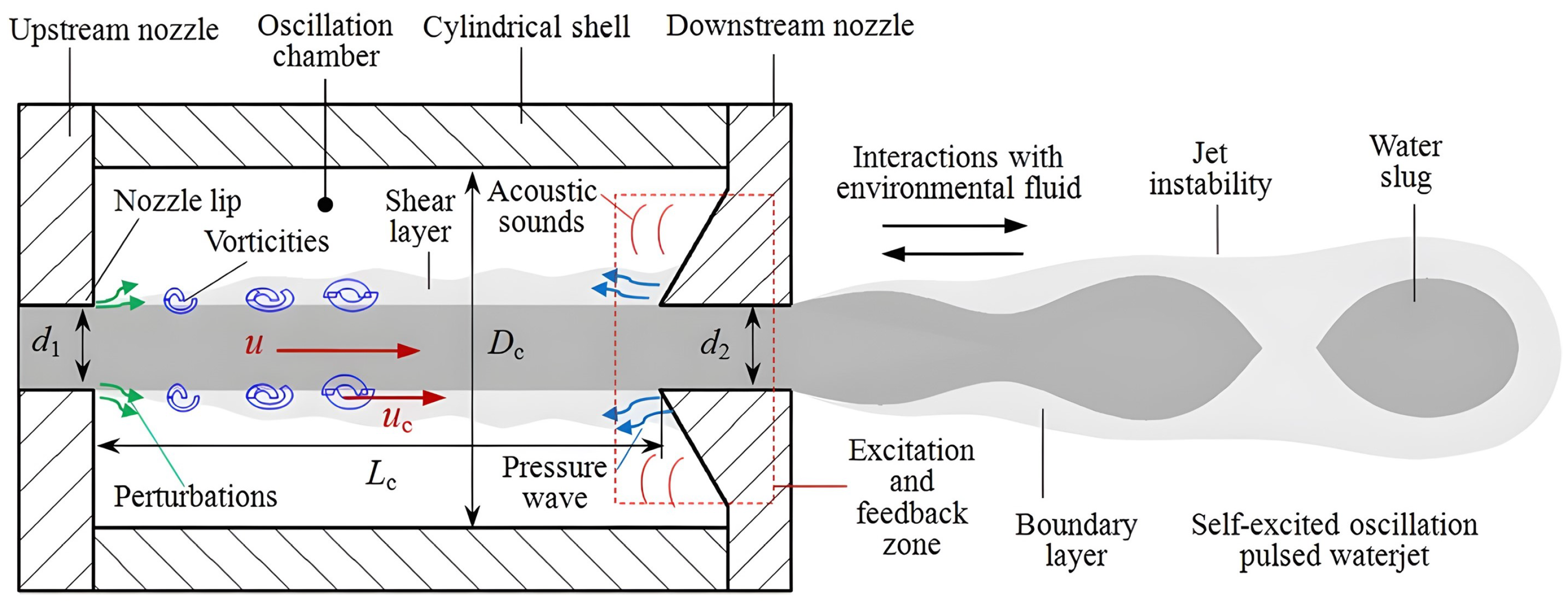
Liao et al. [46] proposed the Helmholtz self-excited pulse nozzle in 1986 based on Johnson’s research using the instability of the shear flow and based on the boundary layer theory and the vortex theory. The structure of the nozzle is shown in Figure 5, including the upstream nozzle, parts such as the upper oscillating cavity wall, oscillating cavity, lower oscillating cavity wall, lower nozzle and so on. The upper nozzle is connected with the incoming flow and flows out from the lower nozzle through the oscillation cavity. As the jet fluid passes through the outlet section of the upstream nozzle, initial disturbances arise from the sensitive regions of the jet, affecting the shear layer near the nozzle lips. These disturbances generate localized vorticity fluctuations within the shear layer. The induced vortex moves downstream while being selectively amplified by the inherent instability of the jet’s shear layer. The amplified shear layer then impacts the impingement edge, producing an organized disturbance wave near this edge. These waves propagate upstream and are further amplified through Helmholtz resonance. Upon reaching the nozzle tip, the disturbances are significantly intensified, leading to high-intensity vorticity fluctuations that initiate the next cycle. When the jet’s structural frequency aligns with both the natural frequency of the Helmholtz oscillation nozzle and the dominant disturbance wave frequency, resonance occurs, resulting in the strongest periodic disturbances within the chamber. Thus, the interplay between strong disturbances, jet shear layer instabilities, and the interaction between the jet and the surrounding fluid forms a large-scale vortex ring and a high-intensity cavitating jet. To better understand the resonance mechanism, the mathematical representations of the three relevant frequencies are provided below. The structuring frequency of the jet, f s , is defined as follows:
f s = S t u d 1
Typically, the Strouhal number S t is 0.2–1.0. According to the previous studies, the natural frequency of the Helmholtz oscillation nozzle f n can be obtained by [61,62]
f n = c 2 π A 0 V l 0 + δ d 0
where c is the local sound speeds, A 0 is the cross-section area of the Helmholtz nozzle inlet, V is the volume of the chamber, l 0 is the length of the Helmholtz nozzle inlet, and δ is the frequency correction factor, 0.6. For the frequency of disturbance waves, f w it can be written as follows:
f w = N L c 1 c + + 1 c
where c + and c are the sound velocity traveling upwards and downwards, respectively, and can be written as follows:
c + = c + u
c = c u

2.3.2. Organ Pipe Type Self-Excited Cavitating Jet

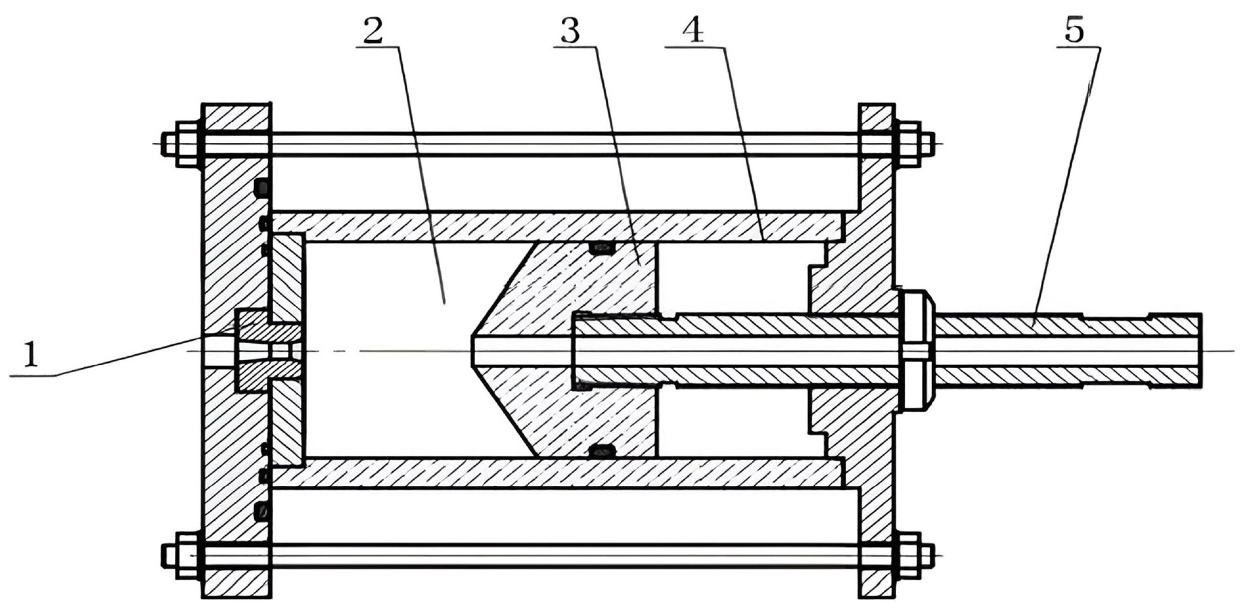
The organ-pipe type self-excited jet is based on fluid transients and hydro-acoustic theory [63]. It offers advantages such as a simple structure, non-thermal operation, and environmental protection [64]. The working principle of the organ-pipe self-oscillating pulse jet nozzle is illustrated in Figure 6. The system uses an organ-pipe excited cavity, with a length L and diameter D, as the excitation amplifier. The inlet of the excited cavity connects to the incoming flow pipe, which has a diameter D s , forming the upper constricted section. The outlet of the excited cavity connects to the jet outlet, which has a diameter d, forming the lower constricted section. The lower constricted section acts as the excitation generation mechanism, while both the upper and lower constricted sections serve as excitation feedback mechanisms.
As the fluid passes through the lower constricted section from the excited cavity, a pressure wave is generated due to the sudden change in fluid pressure and velocity. This wave propagates upstream, reflects off the upper constricted section, and superimposes with the incident wave. When the wavelength of the superimposed wave matches the conditions of the excited cavity’s length, a standing wave forms. If the frequency of the standing wave coincides with the frequency at which the jet naturally tends to structure itself, the vortex in the jet’s shear layer is excited, forming a large-scale vortex ring, significantly enhancing the jet’s cavitation ability.
Furthermore, the generation, growth, and collapse of these large-scale vortex rings induce strong jet flow and pressure pulsations. These pulsations, coupled with the pressure fluctuations caused by standing waves in the excited cavity, amplify each other, leading to large-scale pulsation and the formation of a self-excited oscillating pulsed water jet. Peak resonance is achieved when the acoustic natural frequency of the excited cavity closely matches the self-excited frequency [56]. The fundamental self-excited frequency, f * , generated by vortex shedding, can be expressed as follows:
f * = S t v d
where, d and v are the diameter and velocity of the jet, respectively, and S t is the Strouhal number.
The organ pipe’s acoustic natural frequency f n is primarily determined by the chamber length L, and can be expressed as follows:
f n = K n c L
For D s d > 1 , the “mode parameter” K n is given by the following:
K n = n 2 , 2 n 1 4 , D d < 1 M ; D d < 1 M ;
where M is the Mach number.
For the two mechanisms of oscillatory cavitation: Helmholtz type self-excited cavitating jet and organ pipe type self-excited cavitating jet, comparative studies demonstrate that, under specific conditions, one mechanism may outperform others, especially in terms of achieving a balanced cavitation distribution. A recent trend in oscillatory cavitation research focuses on self-excited pulsed jets, which convert continuous jet energy into high-impact pulses, effectively increasing localized impact pressures for applications such as surface treatment. Nonetheless, achieving uniform cavitation distribution remains a challenge, and future studies could benefit from exploring the stabilization techniques for oscillatory jets to enhance their efficacy in larger-scale applications.

2.3.3. Dual-Chamber Self-Excited Oscillating Pulsed Nozzles

Although significant research has been conducted on self-excited oscillatory cavitating jets, particularly on organ-pipe and Helmholtz nozzles, it remains challenging to substantially enhance the pulsation performance of certain nozzles by adjusting key design parameters. At an international conference held in the United States in 2007, Hlavac introduced a composite nozzle design combining an organ pipe and a Helmholtz chamber [65,66], utilizing two chambers to produce a self-excited oscillating pulsed water jet. The study demonstrated that the effective coordination of the two excited chambers could significantly enhance fluid resonance, leading to improved performance. However, to date, the literature on this composite nozzle is limited, and the flow field structure and pressure pulsation patterns within the nozzle have been rarely examined.
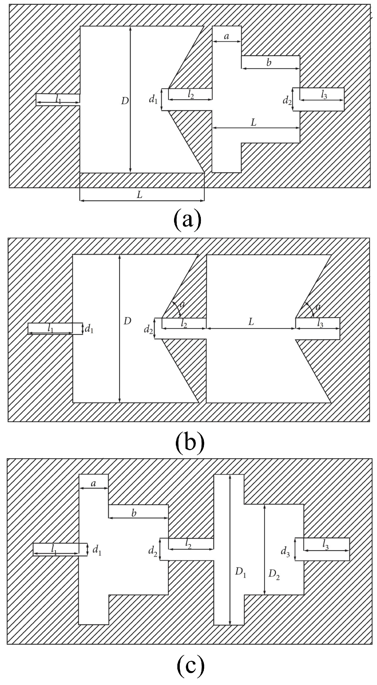
Wang et al. [67] designed an organ-pipe-Helmholtz composite nozzle and experimentally investigated the effect of geometric parameters on the pressure characteristics of self-excited oscillatory jets. They determined the optimal geometric parameters of the organ pipe Helmholtz composite nozzle based on the design principles of organ pipe and Helmholtz nozzles. Shi et al. [68] performed a comparative analysis of the internal cavitation characteristics of Helmholtz-organ pipe nozzles, Helmholtz–Helmholtz nozzles, and organ-pipe–organ pipe nozzles using a combination of numerical simulations and experimental validation. Their findings revealed that the Helmholtz-organ pipe dual-chamber self-excited oscillating nozzle exhibited the highest water vapor phase volume fraction, jet velocity, and turbulent kinetic energy. Additionally, a symmetrical vortex ring was observed inside the cavity, which facilitates pulse jet formation and enhances cleaning efficiency. Moreover, the cavitation phenomenon varied depending on the dimensionless ratio between the cavity and the wall ( D / a ). The internal structure of the associated composite nozzle is shown in Figure 7. The jet pulsation generated in the first oscillation chamber is amplified upon entering the second oscillation chamber, meaning that the slight disturbance is amplified twice. As a result, under the same pump pressure, the dual-chamber self-excited oscillation nozzle produces stronger pulsation compared to the organ pipe or Helmholtz nozzles operating individually.

2.3.4. Factors Influencing the Strength of Self-Excited Cavitating Jet

The optimal effect of the self-excited pulsed cavitating jet is closely related to the pulse frequency, a key parameter for maximizing jet performance and energy output [46,69,70]. At a specific frequency, the energy output of the pulsed jet becomes non-uniform, generating pressure oscillations on the working surface. These oscillations induce continuous alternating stresses, which significantly improve the effectiveness of the jet in applications such as cleaning, cutting, and material removal. The relationship between jet frequency and efficiency has been widely studied, as specific pulse frequencies can lead to better results, particularly in terms of cavitation bubble generation and collapse, which are critical for the jet’s destructive power [71,72].
The structural dimensions of the self-excited pulsed cavitation nozzle play a crucial role in determining the amplitude and frequency of the jet impact force. Qu et al. [60] conducted 25 sets of orthogonal experiments on nozzle structural parameters and identified the suction nozzle diameter as the most important parameter, affecting both the inlet pressure and velocity. This diameter determines the volume and speed of fluid entering the nozzle, which directly influences the cavitation intensity and pulsation frequency. The discharge nozzle diameter also plays a vital role [73], ensuring smooth flow conditions for the pulsating fluid and facilitating the formation of a strong periodic jet in the downstream region.
The other structural parameters—cavity diameter, cavity length, and collision angle—were found to have a similar influence on the self-excited pulsed jet, albeit to a lesser degree. Specifically, the low-pressure range increases with the chamber diameter, a phenomenon that is crucial for the generation of periodic variations in the cavitation air pocket. This, in turn, affects the effective kinetic energy output of the jet [74]. The oscillation chamber length also significantly affects the jet’s frequency and amplitude. An increase in chamber length tends to decrease pulse frequency but increase amplitude, leading to a more potent jet in specific industrial applications where deeper penetration or stronger impact is required [62]. In their research, Xiang et al. [75] explored the periodic nature of pulsed jets using a custom-designed experimental setup (Figure 8). Their findings revealed that both inlet pressure and chamber length play a decisive role in the frequency and amplitude of the jet: higher inlet pressure leads to an increase in pulse frequency but a decrease in amplitude, while a longer oscillation chamber length reduces pulse frequency and increases amplitude. This insight is critical for the design of self-excited pulsed nozzles, where specific applications may require the fine-tuning of both parameters to achieve the desired performance [37].
In addition, the properties of the working fluid (e.g., viscosity, density, surface tension) distinctly influence the nature and effectiveness of cavitation. Understanding these effects is essential for optimizing cavitating jet applications. Thaker et al. [76] utilized a hydrodynamic cavitation device with a glycerol–water solution as the working fluid to investigate the effect of viscosity on cavitation onset. They found that the pressure drop and throat velocity required for cavitation initiation increased with rising viscosity. Zeng et al. [77] established a functional relationship between cavitation shear stress and liquid viscosity using axisymmetric volume-of-fluid (VOF) simulations, accurately predicting the dynamic changes in cavitation bubbles and liquid film thickness. Iwai et al. [78] employed a photosensitive wetting agent to adjust the surface tension of water, examining the mechanism by which surface tension influences cavitation intensity. Their findings indicated that surface tension affects the size and quantity of cavitation bubbles; a reduction in surface tension promoted bubble growth and collapse instability, causing bubbles to split into smaller, lower-energy bubbles and thus reducing the peak pulse energy of the cavitation jet.
In practical applications, to maximize the jet’s impact force, it is essential to ensure that the main frequency of the pressure oscillation wave is singular, minimizing the effects of noise waves. This ensures a more concentrated and powerful pulse, which is especially important in high-precision operations such as precision drilling and micro-abrasion processes [79].

2.3.5. Erosion Patterns of Self-Excited Cavitating Jet

In the study of the dynamics of self-excited cavitating jet bubbles, it was found that the immense pressure generated inside the bubble during collapse propagates outward in the form of pressure waves, with these pressure pulses causing material failure in a manner similar to the water hammer effect [58]. Pan et al. [80] examined how the cavitation number, dimensionless standoff distance ( s / d ), and three erosion modes of self-excited oscillatory jets produced by organ pipe nozzles are interrelated. By evaluating cavitation intensity through the sample’s mass loss, they observed that cavitation intensity decreases as the cavitation number rises. For lower cavitation numbers, two optimal standoff distances result in peaks in mass loss. As the cavitation number increases, the second peak’s standoff distance diminishes monotonically, the effective impingement range contracts significantly, and only one optimal standoff distance remains observable.
Figure 9 displays experimental images of various erosion modes. The formation of a large shallow outer ring and a smaller inner ring within the main erosion zone, observed at different standoff distances, is attributed to the collapse of residual cavities. Pattern A, a typical erosion mode linked to the first mass loss peak is characterized by a prominent erosion ring separated from the central erosion zone and appears at smaller standoff distances. This pattern exhibits the largest erosion area among all modes. Around the second peak, two distinct patterns are observed as follows: Pattern B, featuring a single main erosion ring, corresponds to the highest cavitation intensity and becomes increasingly dominant with larger standoff distances; Pattern C, marked by an additional small inner erosion ring, is confined to a narrow range of standoff distances and cavitation numbers.
The variation in cavitation intensity and erosion patterns underscores the significance of selecting an optimal standoff distance for specific applications of the self-excited cavitating jet. At smaller standoff distances, the formation of a large erosion area enhances the jet’s effectiveness in surface hardening. In contrast, deeper erosion generated at larger standoff distances is better suited for material removal or other high-intensity erosion applications. Under the conditions of high confining pressure, the effective impinging distance decreases notably, emphasizing the critical role of the optimal standoff distance in improving both peening efficiency and erosion performance.

2.4. Shear Cavitation

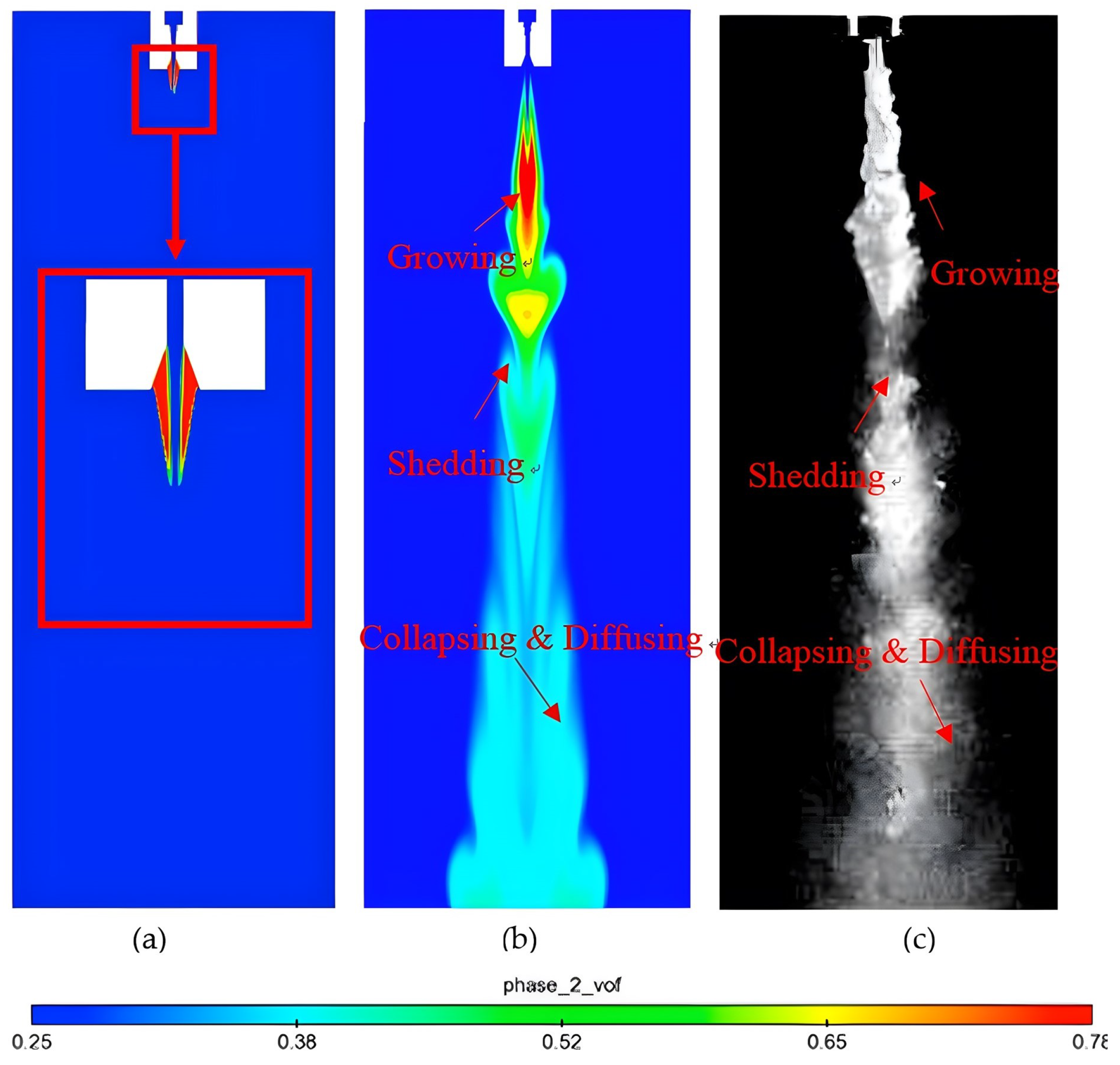
Currently, the most common form of cavitating jet involves injecting a water jet into still water to create a submerged jet. Due to the large velocity gradient at the jet boundary, the viscous forces of the water, along with the reverse pressure differential, result in a boundary filled with vortices [82,83,84]. When the pressure within the vortex core drops to the saturated vapor pressure of water, cavitation occurs, leading to the formation of a submerged shear cavitating jet. Comparisons indicate that the vapor volume fraction in the central area of the jet, near the nozzle exit, is nearly zero, while an annular cavitation zone exists in the high-speed shear layer surrounding this central area. Additionally, concentrated vortices form within the jet. As these vortices move downstream, they grow before detaching from the main cloud, subsequently collapsing and spreading. This process can be categorized into three distinct zones: the growth zone, the shedding zone, and the collapse zone, as illustrated in Figure 10.
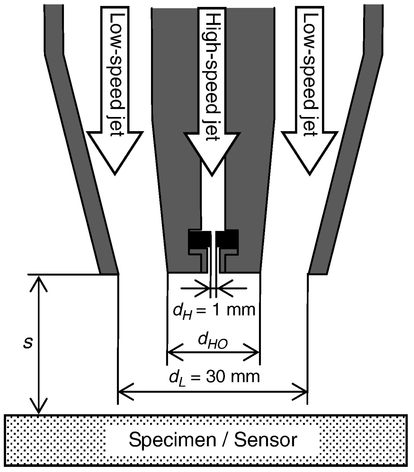
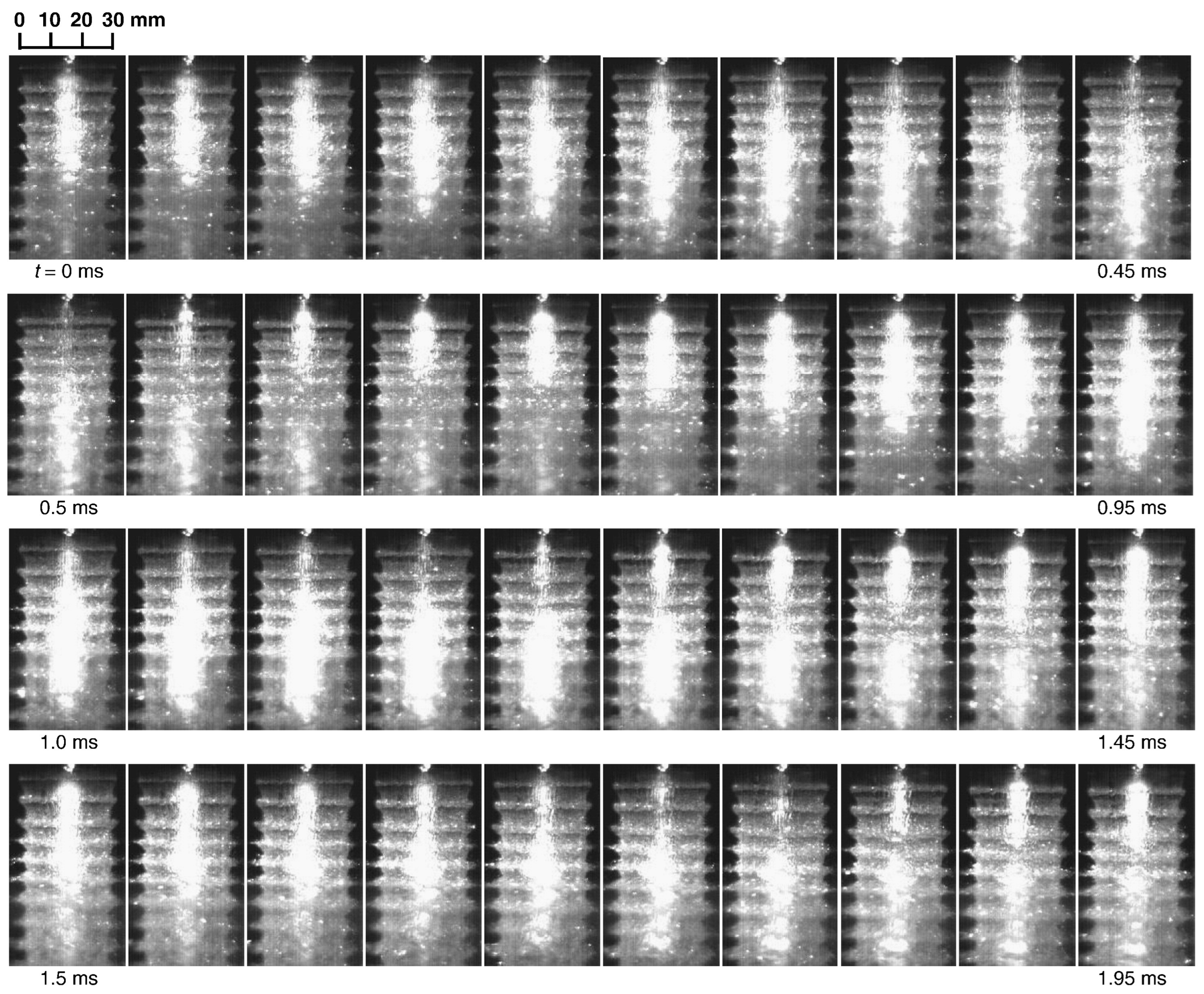
As early as 2004, to enhance the application of cavitating jets, Soyama et al. [86] innovatively proposed the use of cavitating jets in air. The test nozzle is depicted in Figure 11. The nozzles are arranged in a concentric structure, primarily consisting of high-speed and low-speed water jets. The principle of cavitation involves generating shear-type cavitation at the boundary between the high-speed and low-speed water jets [87]. Results captured by a high-speed camera are shown in Figure 12. At times t = 0 ms, 0.7 ms, and 1.35 ms, a wave pattern is observed with low velocity near the nozzle outlet. The interval between wave patterns is approximately 0.65 ms or 0.7 ms, indicating a waveform frequency of about 1.5 KHz. The cavitation cloud in the low-velocity water jet increases over time and subsequently ruptures at t = 0.55 ms, 1.2 ms, and 1.85 ms, with the cavitation cloud detaching in a regular manner. The interval between cloud shedding is approximately 0.65 ms, corresponding to the wave pattern observed in low-velocity water jets. For an optimal cavitating jet in the air, the wave pattern frequency and cloud shedding frequency are synchronized.
When a cavitating jet directly enters the atmosphere, its cavitation effect rapidly diminishes, and the resulting erosion energy cannot be fully harnessed. To address this, Liu et al. [88] utilized Fluent software to visualize the nozzle, discovering that the dynamic inundation environment at the exit effectively extends the nearby low-pressure cavitation area (Figure 13). Experiments have demonstrated the enhancement of cavitation effects in atmospheric jets through the use of an annular cavitation nozzle. As the jet flows through the nozzle’s contraction section and throat, the cross-sectional area decreases rapidly, causing the pressure to drop to the liquid’s vapor saturation pressure, which initiates cavitation in the expansion section. Cavitation can also occur outside the nozzle, near the outlet, even under nonsubmerged conditions. The annular jet establishes dynamic submersion conditions for the cavitating jet, expanding the low-pressure cavitation zone near the nozzle outlet and effectively extending the nozzle’s inner wall. A shear interaction between the cavitating jet and the annular jet generates a low-pressure vortex ring in the air region, enabling the cavitation to persist.
Characterizing the response of solid materials to flow is a common approach in materials science [80]. Kang et al. [44] found that the erosion effect of jets on solid walls is more pronounced in submerged conditions compared to non-submerged ones. Their study focused on the local morphological changes in solid walls under the influence of jet streams, highlighting the importance of target distance as a key parameter affecting the degree of cavitation. Erosion under submerged conditions primarily results from cavitation [44,81]. Fujisawa et al. suggested that the erosion caused by cavitating jets may stem from cloud collapse. They investigated the relationship between crater formation and cavitation collapse events by observing both crater formation and the cloud structure in cavitating jets. Their results indicated that cavitation craters form at the moment of cavitation cloud collapse; however, crater formation does not always occur during these collapse events [89].
The cavitation number is the primary factor influencing the cavitation pattern of submerged shear jet [90]. Analysis using the frame difference method indicates that jet cavitation mainly arises in the vortex structures generated by the shear layer at the nozzle exit, with the most severe collapse occurring at the rear end of the downstream section after the bubble cloud is shed. A lower cavitation number correlates with higher exit jet velocity and stronger cavitation intensity [37,90]. Both factors significantly affect the distribution and intensity of bubbles along the jet coordinates. As pressure increases, the size, concentration, coherence, and area fraction of the cavitation cloud significantly rise [30]. This shift also causes the location of cavitation cloud rupture to move downward, thereby increasing the optimal working distance, while the development of cavitation and collapse frequency decreases markedly [37,90].
Furthermore, the shedding frequency of the cavitation cloud and the pressure fluctuations of the jet are related to the self-oscillation of the fluid through the nozzle, with appropriate nozzle geometry determining both cavitation intensity and distribution [37,91]. Consequently, optimizing nozzle geometry can enhance cavitating jet performance. Yang et al. [90] found that a nozzle dispersion angle near 80° resulted in the improved concentration and distribution of cavitation bubbles. To maximize the axial vapor volume fraction in a submerged shear cavitating jet, Chen et al. [91] analyzed the effects of eight geometric parameters and utilized computational fluid dynamics techniques to propose a hybrid optimization algorithm. Their optimal model demonstrated effective cavitation performance across various water depths, with a maximum axial vapor volume fraction increase of 9.41% at 50 m underwater, and the most substantial improvements noted at 100 m. This optimized nozzle structure mitigates the cavitation inhibition caused by increased ambient pressure, significantly enhancing cavitation effectiveness in deep water and improving operational efficiency. Notably, the diameter of the cylindrical cross-section, along with the contraction and diffusion angles, significantly influences the maximum axial vapor volume fraction. In contrast, the lengths of individual sections typically have a lesser impact compared to the angles. Various shear cavitation designs exhibit unique performance characteristics suited for different applications. Multi-nozzles [92,93,94] show higher stability and adaptability in large-scale applications where uniform cavitation distribution is essential. In contrast, single-nozzle and annular jet nozzle designs [94,95], which deliver stronger shear forces, are ideal for targeted material erosion. The versatility of adjustable shear nozzles makes them suitable for applications that demand customizable cavitation effects. These comparisons demonstrate how the choice of shear cavitation nozzle design directly impacts performance metrics like stability and energy efficiency, underscoring the importance of selecting designs tailored to specific operational needs.
Shear cavitation, characterized by its reliance on velocity gradients and boundary layer interactions, differs from other methods by providing targeted cavitation along specific flow paths. Recent advancements have focused on optimizing nozzle geometries to increase axial vapor volume fractions, indicating a trend toward applications in deeper underwater environments where pressure stability is essential. Comparatively, shear cavitation offers unique advantages in controlling cavitation zones and sustaining bubble longevity in varying pressure conditions. However, challenges remain in achieving consistent cavitation effects in turbulent flows. Future research may explore hybrid shear-cavitation nozzles, combining aspects of the central body and oscillatory designs to enhance performance in complex flow environments.

2.5. Other Methods of Cavitating Jet Generation

2.5.1. Ultrasonic Cavitation

Ultrasonic cavitation is a phenomenon where, under sufficient ultrasonic energy, microscopic bubbles (cavitation nuclei) within the liquid vibrate, expand, and accumulate energy continuously from the sound field. When this energy reaches a specific threshold, the cavitation bubbles collapse sharply [49]. Acoustic cavitation bubbles are believed to arise from non-uniform nucleation, as this process requires less energy compared to uniform nucleation. A typical nucleation site is a minute crack filled with gas, often referred to as a “gas pocket”. Numerous microcracks can exist on the reactor wall or the surface of the electrode array used for cavitation treatment. When the acoustic pressure amplitude and crack size are sufficiently large, the non-uniformly nucleated cavitation bubbles detach from the solid surface [96], as shown in Figure 14.
The evolution of ultrasonic cavitation is closely related to pressure fluctuations and fluid turbulence [97,98]. An increase in amplitude effectively increases the cavitation intensity, while an increase in frequency diminishes cavitation. A 78% increase in the maximum volume fraction was found when the amplitude was increased by 20 µm in the experiments of Lv et al. [98]. The maximum gas phase volume fraction occurs near the target surface during the downward motion of the workpiece, whereas cavity formation is influenced by compression during the upward motion. As the jet velocity decreases, the cavitation intensity is enhanced due to lower stagnation pressure and stronger turbulent diffusion. At the same time, the gas phase fraction decreases with increasing working distance due to the attenuation of ultrasonic waves. Experiments show that the synergistic erosion of microjets and accelerated particles caused by the collapse of cavitation bubbles can significantly improve the material removal capacity. Under the conditions of ultrasonic vibration, the material removal rate can be increased by up to 82% [98].
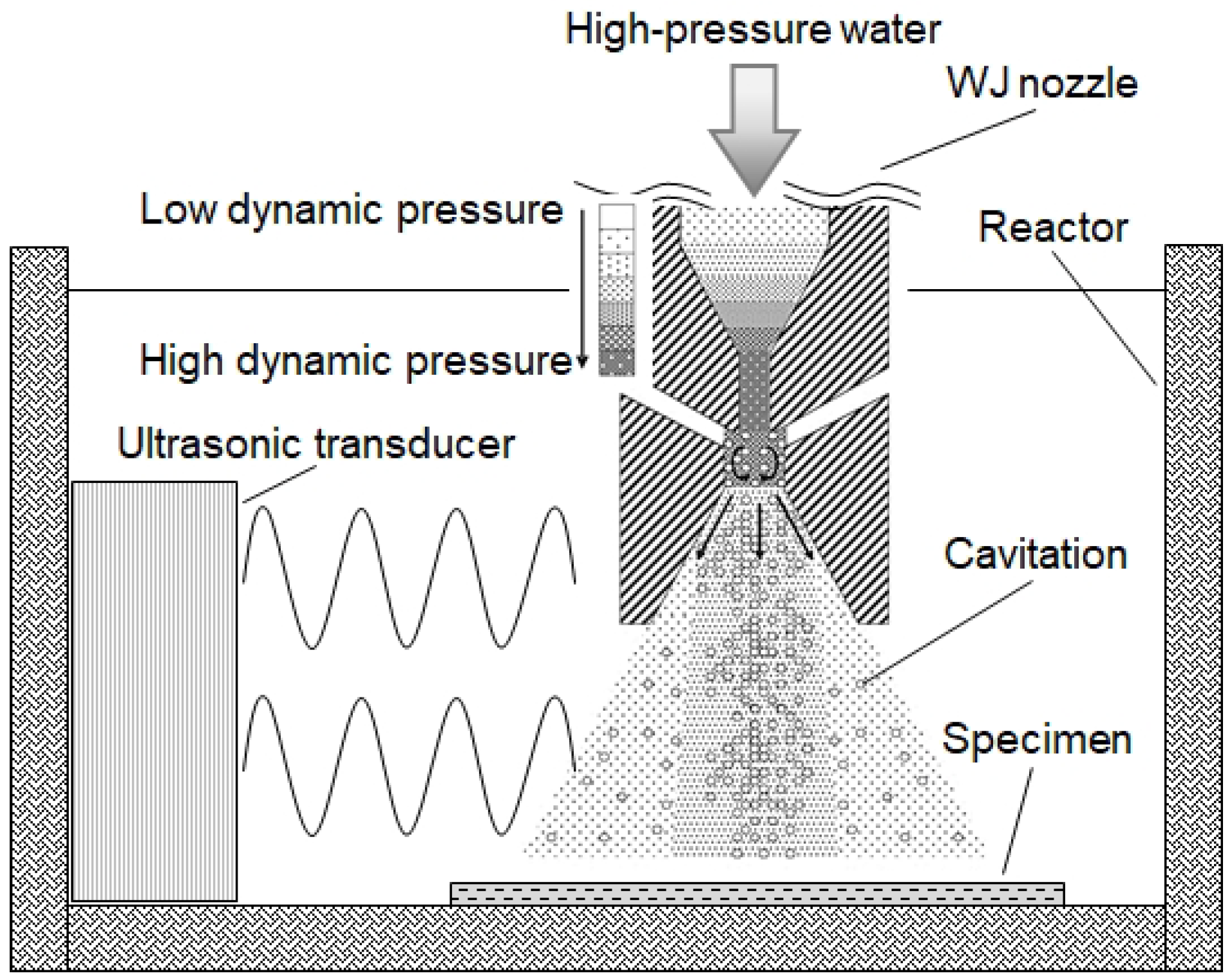
Acoustic cavitation in liquid media produces a number of physical and chemical effects that can be used in a variety of cleaning applications. Under the drive of low ultrasonic frequency (20 kHz), the oscillation and collapse of cavitation bubbles will produce strong shear forces, micro jets and shock waves. The intense physical forces generated by ultrasonic cavitation are effective for cleaning and enhancing flux in ultrafiltration processes and have also demonstrated pathogen inactivation capabilities [99,100]. Additionally, the strong oxidants formed during acoustic cavitation can degrade organic pollutants and convert toxic inorganic compounds into less harmful substances, thereby contributing to water purification [101]. In addition, ultrasonic cavitation can also be used to improve the mechanical properties of the cavity’s inner surface. Shot peening is a common method to improve stress concentration and prolong working life in the common surface treatment of materials. But this method makes it difficult to deal with the inner surface of the cavity in the component. The new ultrasonic cavitation method proposed by Bai et al. [102] can better solve this problem. The working principle is that the fluid enters through the narrow gap between the special shape acoustic electrode tube and the inner surface to produce cavitation on the inner surface of the cavity; it has a good effect.
Ultrasonic cavitation offers unique capabilities, especially when adjusted across frequency ranges, which distinguish it from traditional hydrodynamic methods. Current research is exploring the potential of combining ultrasonic and hydrodynamic cavitation to create a dual-effect approach, maximizing both material processing and environmental cleaning applications. Further investigation is needed to optimize these combined approaches for greater cost-effectiveness and energy efficiency.

2.5.2. Laser Induced Cavitation

The principle of laser cavitation is analogous to that of laser impact on a target in a liquid medium. However, in laser cavitation, the laser is not focused directly on the material but rather aimed at a distance above it. When the laser energy is sufficiently high, the phenomenon known as “laser cavitation” occurs. This phenomenon arises when the laser energy reaches the breakdown threshold, stimulating the formation of a small bubble in the liquid—namely, cavitation. As energy accumulates, a pressure difference develops between the inside and outside of the cavitation bubble. This pressure differential causes the cavitation to expand toward the surrounding liquid. Additionally, the pressure within the bubble decreases. Due to inertial effects, the cavitation bubble compresses to its minimum radius, marking the first pulsation process and generating a shock wave. Following this compression, the cavitation pulsates again and releases another shock wave. As the energy attenuates, the cavitation eventually collapses [51,103,104].
The shock wave generated by the laser cavitating jet, along with the pressure intensity of the jet, decreases with increasing working distance [105]. This phenomenon can be utilized for cleaning and enhancing the surfaces of materials. The shock wave released during pulsation effectively removes the contaminants from nearby targets. Due to the constraints imposed by the solid target, the vacuole cannot expand symmetrically, leading to a reduction in motion speed near the target. This results in a pressure gradient on the vacuole’s surface, which drives it toward the target—a phenomenon known as the converging wall effect. As the bubble collapses during its motion, it generates shock waves and micro-jets directed at the target’s surface, thereby cleaning it. Laser cavitation blasting is a composite impact process involving laser shock waves, bubble collapse shock waves, and water jets, with the laser shock wave playing a dominant role. This process can induce plastic deformation of the material surface and refine the grain structure at specific depths while significantly reducing surface roughness. The improvements in residual stress and microhardness achieved through laser cavitation blasting are proportional to the working distance.
Several researchers have investigated the kinetic properties of laser-induced cavitation bubbles near rigid walls and their effects on the rupture of turbulent liquid jets. Zhang et al. [106] conducted experimental studies on the impact of particles on the collapse kinetics of laser-induced cavitation bubbles near solid walls. They found that particle size had no significant effect on the kinetic behavior of the bubbles, except at certain specific locations. Brujan et al. [107] discovered that in the presence of two perpendicular rigid walls, the jet penetrates the opposite bubble surface, creating an asymmetric ring bubble oriented perpendicular to the jet direction. As the bubble collapses radially from a distance away from the rigid wall, it eventually disintegrates into smaller microbubbles. When the bubble contacts the horizontal wall surface at its maximum expansion, it collapses both radially and annularly from the section opposite the vertical wall, resulting in a crescent shape during the second collapse. Oscillations of the bubble are observed to migrate strongly along the horizontal wall surface. Additionally, it was observed that as the bubble approaches the vertical rigid wall, the liquid jet formed during its collapse becomes increasingly inclined, resulting in an earlier ring collapse during the second oscillation cycle. When positioned directly adjacent to the vertical wall, the ring surface tilts at 45° and collapses exclusively in the radial direction. Zhou et al. [108] found that the surface deformation and fragmentation of the jet occur in two stages: the first stage involves the early separation of the liquid string into small droplets, followed by the formation of larger deformed structures. The second stage encompasses the disintegration of these larger structures into ligaments and larger droplets. The radial position of the laser focus influences the degree of jet deformation, droplet size, and the uniformity of droplet distribution in nearly all cases, although the qualitative behavior remains similar. It was also observed that lower surface tension facilitates droplet separation and the formation of smaller droplets; structures with lower surface tension exhibit less complete break-up, occur more spontaneously, and are more influenced by aerodynamic forces.
Laser-induced cavitation stands out among cavitation methods due to its precision and the high-energy impacts it produces through controlled laser pulses. This approach is advantageous for applications requiring highly localized material deformation, such as in fine cutting and surface modification. However, challenges remain in minimizing unintended surface damage during high-energy applications. Future research could focus on using adjustable-frequency pulsed lasers to improve control over cavitation bubble dynamics, reducing undesired thermal effects.

3. Applications of Cavitating Jets

Under the same conditions, the impact force of cavitating jets is several times greater than that of continuous water jets, with the impact strength generated during the collapse of cavitation bubbles exceeding 400 MPa [109,110]. Due to this remarkable performance, cavitating jets are utilized in various applications, including enhancing the surface performance of materials, cleaning, material cutting, rock crushing, and energy exploration.

3.1. Application in Improving the Surface Performance of Materials

3.1.1. Surface Material Strengthening

Shot peening is a widely utilized surface modification technique for improving the mechanical properties of metallic materials. Unlike traditional methods, cavitation shot peening does not involve solid collisions, resulting in minimal increases in surface roughness. Consequently, cavitation shot peening has evolved into an advanced surface modification technology.
Soyama et al. [111] conducted cavitation shot peening on friction stir welded sheets, finding that it significantly reduced the fatigue crack growth rate of duralumin plates, increasing their fatigue life by 4.2 times. Additionally, during the stable crack propagation stage, cavitation shot peening suppressed crack growth by 88%. Marcon et al. [112] employed cavitation generated by the shear layer of two concentric co-flow jets with a significant velocity difference to apply compressive side stress on the surfaces of metal components exposed to fatigue or corrosive environments. Takakuwa et al. [48] demonstrated that the residual compressive stress induced by cavitation shot peening reduces hydrogen intrusion on the surfaces of austenitic stainless steel. Furthermore, Takakuwa et al. [113] reported that cavitation shot peening significantly improved the fretting fatigue performance of spinal implant fixation devices, achieving a performance increase of 2.2 times compared to untreated devices, with hardness rising from 5.0 GPa to 9.6 GPa. Latchoumi et al. [114] employed particle swarm optimization (PSO) technology to address issues related to water jet processing and cavitation shot peening, initializing the starting group based on water pressure, station distance, and crossing speed, while estimating fitness based on residual stress, hardness, and surface roughness.
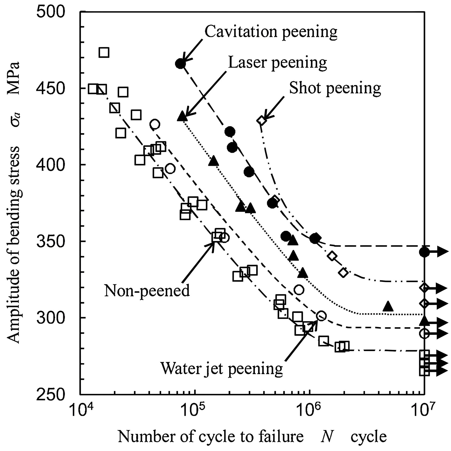
To demonstrate the advantages of cavitation shot peening over other shot peening methods, numerous studies have been conducted by various scholars. Soyama et al. [115] performed both cavitation shot peening and conventional shot peening on specimens with chamfered and rounded holes. The findings indicated that the fatigue life of the shot-peened specimens was equal to or less than that of the chemically treated specimens; however, the fatigue life of specimens subjected to cavitation shot peening increased by more than ten times under maximum tensile stress (up to 150 MPa). In a separate study, Soyama [116] compared the fatigue performance of shot peening with cavitation strengthening, examining crack initiation and propagation in samples of austenitic stainless steel (Japanese Industrial Standard JIS SUS316L). Additionally, Soyama [117] assessed the fatigue strength of 316L stainless steel specimens subjected to cavitation shot peening, water jet shot peening, laser shot peening, and conventional shot peening. The results revealed that the fatigue strength of the untreated specimen was 279 MPa, while the treated specimens showed fatigue strengths of 348 MPa for cavitation shot peening, 325 MPa for conventional shot peening, 303 MPa for laser shot peening, and 296 MPa for water jet treatment (Figure 15).
To further enhance the performance of cavitating jets in improving material surfaces, many scholars have integrated various technologies to create multifunctional cavitation systems. Ijiri et al. [118] explored a multifunctional cavitation (MFC) process that combines water jet cavitation (WJC) with ultrasonic cavitation to enhance the microstructure and hardness of Cr–Mo steel (SCM435). Chen et al. [119] introduced a superhydrophobic preparation technique based on ultrasonic cavitation, where the collapse of bubbles erodes the surface, creating a highly rough microstructure. Subsequently, SiO2 nanoparticles are effectively anchored on the surface by the cavitating jet, resulting in a micro-nano composite structure with excellent superhydrophobic properties. Ijiri et al. [120] utilized water jet peening and multifunctional cavitation to address high-temperature corrosion (500 °C) in Cr–Mo steel, assessing its suitability for high-temperature boilers and reaction vessels. In addition, the optimal cavitation treatment conditions for samples in high-temperature corrosion tests were determined, revealing that samples treated with multifunctional cavitation exhibited higher residual compressive stress after 10 min and greater surface Cr content than untreated samples [121].
In addition, Gu et al. [122] applied the laser cavity strengthening (LCP) method to enhance Q235 steel, utilizing the impact force generated by laser ablation to create local plastic deformation pits that improve the fatigue performance of metal materials. Under appropriate impact conditions, the mechanical performance of A16061 and 304 stainless steel was notably enhanced and introduced a new multifunctional cavitation (MFC) technology that combines ultrasonic and water jet cavitation [123]. The nozzle structure is depicted in Figure 16. This method was used for surface modification of Cr–Mo steel (SCM435) and Ni–Cr–Mo steel (SNCM630). Through surface modification, MFC can increase the material’s residual stress while enhancing strength and corrosion resistance. Traditionally, the ultrasonic cavitation shot peening process requires the sample to be immersed in liquid and involves temperature control, which limits its application to complex geometries. To address this limitation, Bai et al. [124] introduced a technique that sprays water slowly (75 mL/min) into the gap between the sonar tip and the sample surface. This approach allows for the generation of cavitation bubbles in the gap, overcoming the constraints associated with complex shapes in traditional ultrasonic cavitation shot peening.

3.1.2. Surface Polishing

The application requirements of various types of metal parts are becoming more and more stringent, and the surface quality directly affects the compatibility, fatigue strength, wear resistance, corrosion resistance, etc., of metal parts. The collapse of the cavitation cloud produced by the cavitating jet generates intense shock waves and high-energy microjets near the microbubbles, enhancing turbulence and increasing the random motion of abrasive particles within the fluid field. This phenomenon significantly improves the efficiency of fluid polishing, making it a highly promising technique for precision surface finishing [125,126].
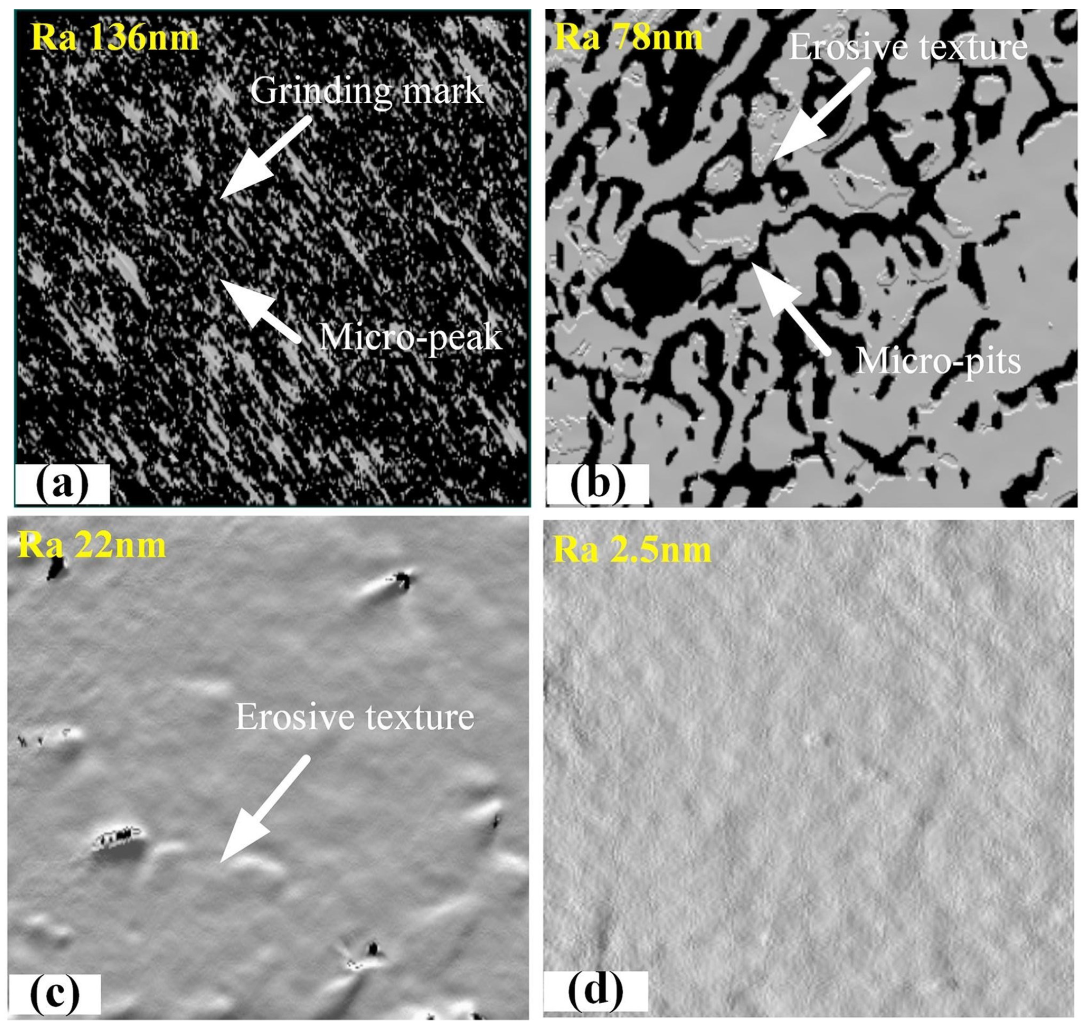
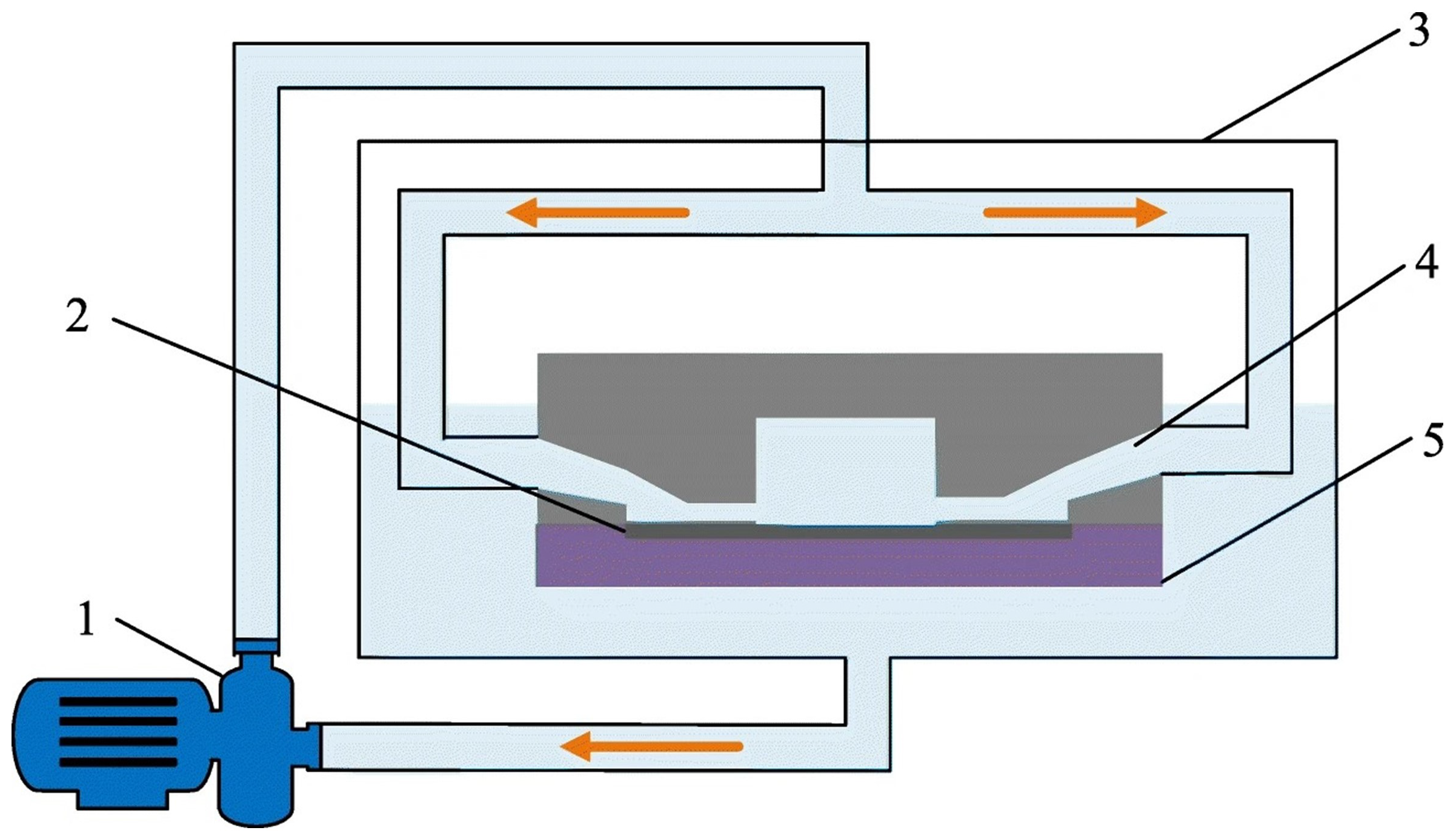
Chen et al. [127] used negative pressure cavitation to study the erosion effect of material removal and surface roughness. As a result, the surface negative pressure cavitation improved the polishing efficiency. Chen et al. [128] proposed a novel cavitation fluid jet polishing (CFJP). It can efficiently polish small-size surfaces under low-pressure environments (Figure 17). CFJP uses specially designed sealing and polishing equipment. In a negative pressure environment, a cavitation effect will occur. In addition, the collapse of cavitation bubbles can generate high-energy microtubules and shock waves to enhance the removal effect of materials. Traditional soft abrasive flow polishing is limited due to its low material removal rate and its suitability for large workpieces. To solve this problem, Ge et al. [129] proposed a cavitation-based gas–liquid–solid abrasive flow polishing (CGLSP) process, as shown in Figure 18. The energy produced by the cavitation effect enhances the kinetic energy of abrasive particles within the fluid flow and their random motion near the surface. The main disadvantage of traditional polishing methods is the very low material removal rate. To address this issue, Beaucamp et al. [130] developed a novel system where ultrasonic cavitation generates microbubbles directly upstream of the nozzle outlet. Experimental results indicate that these microbubbles can enhance the removal rate by up to 380% without compromising surface finish quality.

3.1.3. Surface Material Micro-Forming

Hutli et al. [131] demonstrated the potential for controlled surface modification of metallic biomaterials using cavitating jets. In their study, stainless steel 316, an austenitic face-centered cubic metal, was treated with a high-speed immersion cavitating jet under specific working conditions and varying exposure times. The force generated by the collapse of cavitation bubbles effectively altered the surface morphology at the micro-nano level. Additionally, Lu et al. [132] employed water jets and shock waves produced by laser cavitation to explore laser cavitation micro-forming (LCMF), a novel technique for simultaneously manufacturing microfeatures on two pieces of metal foil. Their experimental results, as shown in Figure 19, indicated that the surface quality of the formed micropores could be enhanced by adjusting the gap width.
As the application range of micro-electromechanical systems continues to expand, micro-device forming technology has achieved significant advancements. However, developing a low-cost, environmentally friendly micro-forming process remains challenging. Li et al. [133] proposed a new water jet cavitation micro-bulging process that utilizes the high-energy shock wave generated during the collapse of cavitation bubbles as the loading force. Their experimental study on the micro-bulging process of TA2 titanium foil revealed that, at an incident pressure of 20 MPa, the maximum deformation exceeded 240 μm, with a thickness reduction ratio of approximately 10%. This finding confirmed the feasibility of water jet cavitation micro-bulging. Furthermore, Li et al. [134] introduced a novel technology for producing micro-feature arrays on 304 stainless steel foil through submerged water jet cavitation impact, highlighting the method’s versatility in creating complex micro-features essential for micro-elements.

3.2. Application in Crushing and Cutting

Cavitation is a widely recognized phenomenon in the aqueous environment at the Earth’s surface, where its mechanical effects contribute significantly to the erosion of rocks in natural settings [135,136]. This process is not only instrumental in shaping landscapes but also serves as a crucial mechanism for the transport of geochemical elements within both the lithosphere and hydrosphere [137,138]. Cavitation processes generate micro-scale cavitation bubbles, which exert mechanical forces that facilitate the dissolution of rock minerals. The effects of these processes are temporally and spatially manifested during the migration of chemical elements between water and rock minerals, highlighting the intricate interplay between physical and chemical processes in geochemical cycling [139].
Numerous studies have explored the mechanisms underlying accelerated rock loss and crush, specifically focusing on phenomena such as abrasion, erosion, and etching caused by flowing water bodies [140,141,142,143]. The crushing of rock by downhole submerged jets occurs in three primary stages: surface cavitation, microcrack generation, and the water wedge effect, which together contribute to the overall erosion process [144,145,146]. In contrast, the mechanisms driving accelerated mineral crystal dissolution have garnered comparatively less attention in the literature. Su et al. [139] proposed a potential mechanism for enhancing the transient dissolution of mineral crystals through cavitation erosion. This was accomplished via theoretical derivation and calculation of Gibbs free energy changes associated with the plastic deformation of mineral crystals, grounded in the theory of crystal dissolution step wave dynamics. The proposed mechanism was qualitatively validated through acoustic cavitation experiments that mimic the erosion processes.
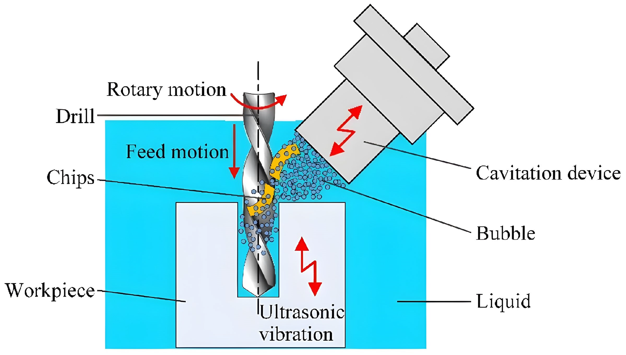
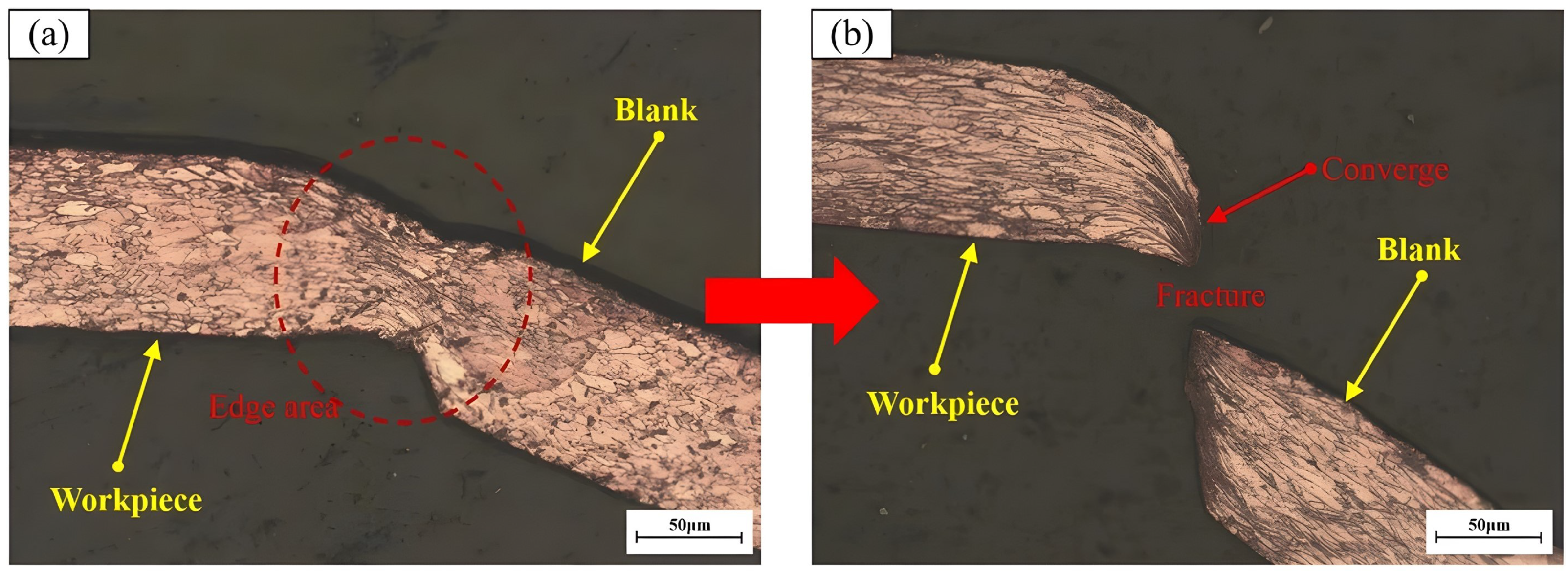
Moreover, the micro-jet, shock wave, and high temperatures produced by the collapse of cavitation near the wall can lead to specific forms of material damage; additionally, the significance of cavitation in material cutting is increasing. Liang et al. [147] utilized ultrasonic cavitation in ultrasonic vibration drilling for machining stainless steel micropores, as illustrated in Figure 20. Their findings demonstrate that this approach significantly improves chip-breaking efficiency, reduces thrust force, prolongs tool life, and achieves superior micro-hole machining quality. Wang et al. [47] investigated the intrinsic mechanisms of cavitating jets applied in the field of microblanking through the microscopic characterization of the blanking and forming processes, as illustrated in Figure 21. Numerical simulations elucidated the evolution modes and pressure characteristics of the cavitating jet, and analyzed the effects of jet pressure and distance on blanking quality, thereby enhancing the overall quality of the blanking process. Tinne et al. [148] optimized the laser pulse energy, energy ratio, and other parameters through femtosecond laser-induced cavitation bubble generation and interaction to achieve corneal tissue cutting at a high repetition rate. Arba et al. [149] developed a theoretical model capable of converting energy fluctuations during the cutting process into equivalent deviations of cavitation bubbles, thereby maximizing cutting efficiency across different materials through the optimization of laser parameters.

3.3. Application in Energy Exploration

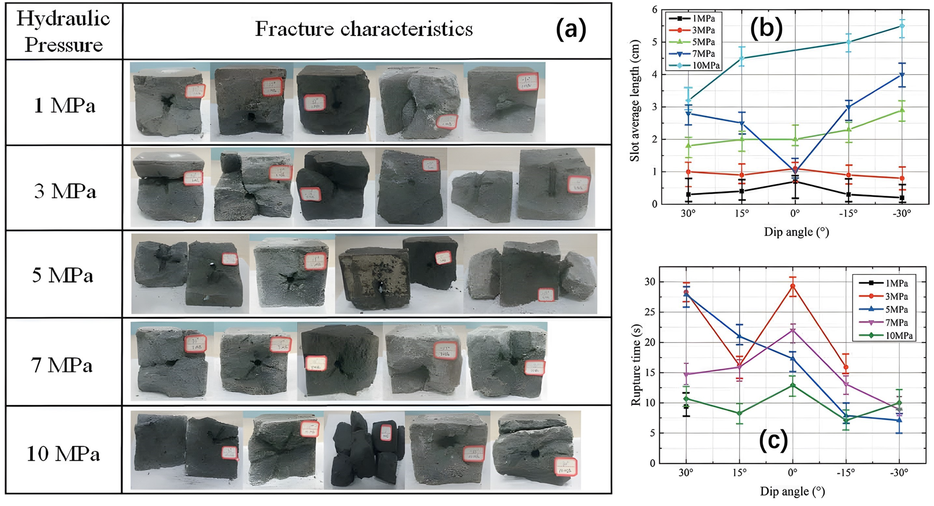
Currently, cavitating jets are extensively utilized in the field of energy exploration due to their environmental friendliness, high efficiency, and adaptability [150]. Coal bed methane (CBM), acknowledged as a clean, efficient, and environmentally friendly energy source, has gained increasing importance in light of the growing global energy demand [151,152]. To enhance coalbed methane desorption and improve gas extraction efficiency, Wang et al. [153] proposed a technical method that facilitates coalbed methane desorption through the acoustic vibration effects of cavitation water jets. The cavitation water jet exhibits a notable acoustic vibration effect during the collapse phase of the cavitation bubble; its powerful impact can enhance the effectiveness of the water jet, fracture the target, and generate substantial mechanical vibration and thermal effects. The study indicates that the acoustic vibration effect of cavitation significantly accelerates methane desorption, with the mechanical vibration effect serving as the primary factor in facilitating coalbed methane desorption. The practical application of this technical method in CBM development is of considerable significance. Hydraulic slotting is an additional technique employed to enhance the recovery rate of CBM and mitigate gas disasters. Guo et al. [144] found through experiments that the cavitation erosion induced by submerged jets can facilitate the formation of fractures under medium to high-impact load conditions. The fracture characteristics resulting from hydraulic grooving are illustrated in Figure 22. The cavitation effect results in a greater average slotting length of the borehole and a reduced fracture time when slotted downstream. The research findings confirmed that a higher water jet pressure [154,155] correlates with enhanced gas extraction efficiency. Achieving the objectives of discharging coalbed methane, reducing greenhouse gas emissions, and effectively preventing gas disasters through hydraulic slotting holds great promise.
Natural gas hydrates (NGH) form and exist within the pores of sedimentary soils on the deep seafloor and in permafrost regions. Given that cavitating jets are an effective method for rock breaking and particularly suitable for eroding soft hydrate sediments, Zhang et al. [156] designed an innovative experimental setup to study the erosion effects of cavitating jets on hydrate materials, aimed at advancing the application of radial jet drilling technology in natural gas hydrate (NGH) reservoirs. A series of experiments confirmed the practicality of cavitating jets for NGH reservoir development. The high-pressure low-temperature conditions common in offshore gas production and transportation often lead to the formation of methane hydrates within tubing or pipelines, causing decreased production efficiency and flow assurance challenges. Huang et al. [157] evaluated the impact of cavitation on hydrate decomposition under various parameters based on experimental data; the results indicated that cavitation significantly promotes hydrate decomposition, with larger cavitation energy leading to enhanced hydrate destruction. Wu et al. [158] enhanced the efficiency of jet erosion and gas hydrate extraction by optimizing the divergence angle, divergence length, and throat length of the cavitation nozzle structure.
In the construction of salt caverns, rapid solution mining is crucial; cavitating jets can significantly enhance the rate of salt dissolution and shorten the cavern construction period during the pocket stage. Song et al. [159] introduced self-excited cavitation water jet rapid solution mining technology. This technology can produce three main physical effects: spiral flow dissolution, self-excited cavitating jet erosion, and ultrasonic waves. Experimental results indicate that, under ambient pressure, the pressure impact amplitude peaks at 5 to 13 times the nozzle outlet diameter (Figure 23), and the erosion or cutting ability of the self-excited cavitating jet on rock is one to two times greater than that of the conventional jet. Compared to conventional mining methods, self-excited cavitating jet fast dissolution technology can significantly enhance the salt production rate and offers advantages such as high hydraulic energy utilization, rapid salt dissolution rates, and good compatibility with other dissolution methods. This technology can markedly enhance the construction quality of salt reservoirs in the West–East gas pipeline project. Additionally, Vijay [160] investigated the potential of high-speed abrasive jets, water jets, and cavitating jets for mining metallic rock minerals, demonstrating that cavitating jets under submerged conditions have considerable potential for the selective mining of metal-bearing rock materials and that the nozzle structure significantly affects mining efficiency. Fang et al. [161] determined the optimal operating parameters of the pulsed cavitating jet in the submerged state and demonstrated that cavitation is a key factor in the destruction mechanism of mineral extraction.

3.4. Application in Cleaning

Cavitating water jets can cause bubbles to burst, generating extremely high impact pressure and stress concentration in localized areas on the surface of an object. This phenomenon can rapidly damage the object’s surface, thereby facilitating material cleaning [162,163]. Liu et al. [164] proposed a method for self-excited pulsed cavitating jet cleaning. An experimental study was performed to optimize cleaning efficiency by evaluating the nozzle’s performance under varying flow rates. The analysis focused on four key aspects: cavitation morphology, pressure pulse frequency, velocity fluctuation amplitude, and erosion effects. The research findings indicate that the flushing effect with the cavitation nozzle is significantly greater than that without the cavitation nozzle. In the erosion effect experiment, the flow rate exhibited minimal influence on the outer diameter of the erosion ring. Fujisawa et al. [89] also demonstrated that annular cavitation nozzles possess a greater rust removal capacity than high-pressure nozzles.
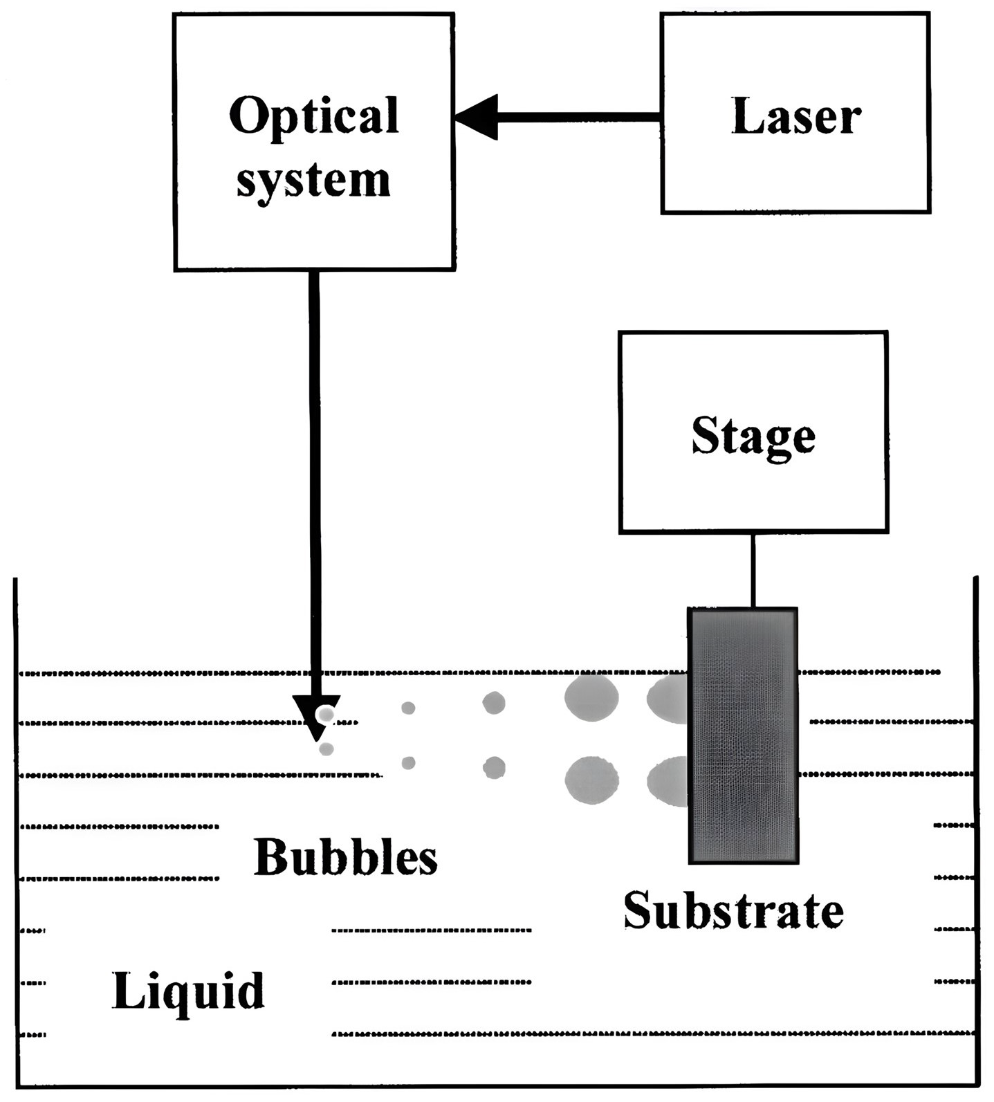
Song et al. [165] proposed a method for cleaning solid surfaces using laser-induced cavitation bubbles, as illustrated in Figure 24. When a rigid substrate is immersed in the liquid, the bubbles migrate toward the substrate due to the Bjerknes gravitational force. It was found that as the bubble approaches the rigid substrate and the liquid surface boundary, the implosion of the cavitation bubble generates a surge and a liquid jet that is angled toward the substrate surface, exerting parallel and perpendicular components of force on the particles. These inclined liquid jets and surge enhance cleaning efficiency. This method effectively removes micron-sized nanoparticles from solid surfaces. Additionally, Ohl et al. [166] experimentally demonstrated, using microparticle tracking velocimetry, that the strongest particle forcing occurs within a brief phase of the bubble oscillation cycle. During this period, the boundary layer flow on the substrate becomes most prominent. The jet impacts the surface and spreads radially, effectively transporting particles and producing a clean surface. Ralys et al. [167] found that directing the cavitation pulsating water jet generated in the nozzle at the surface resulted in a water vapor concentration of 84% in certain areas of the clean surface. This indicates the presence of a strong cavitation zone, leading to the improved removal of contaminants. Bram et al. [168] reviewed several techniques for measuring the presence and quantity of cavitation and quantifying cleaning, listing the advantages and limitations of these techniques, and highlighting that relating cavitation to cleaning effectiveness is an issue requiring further research.
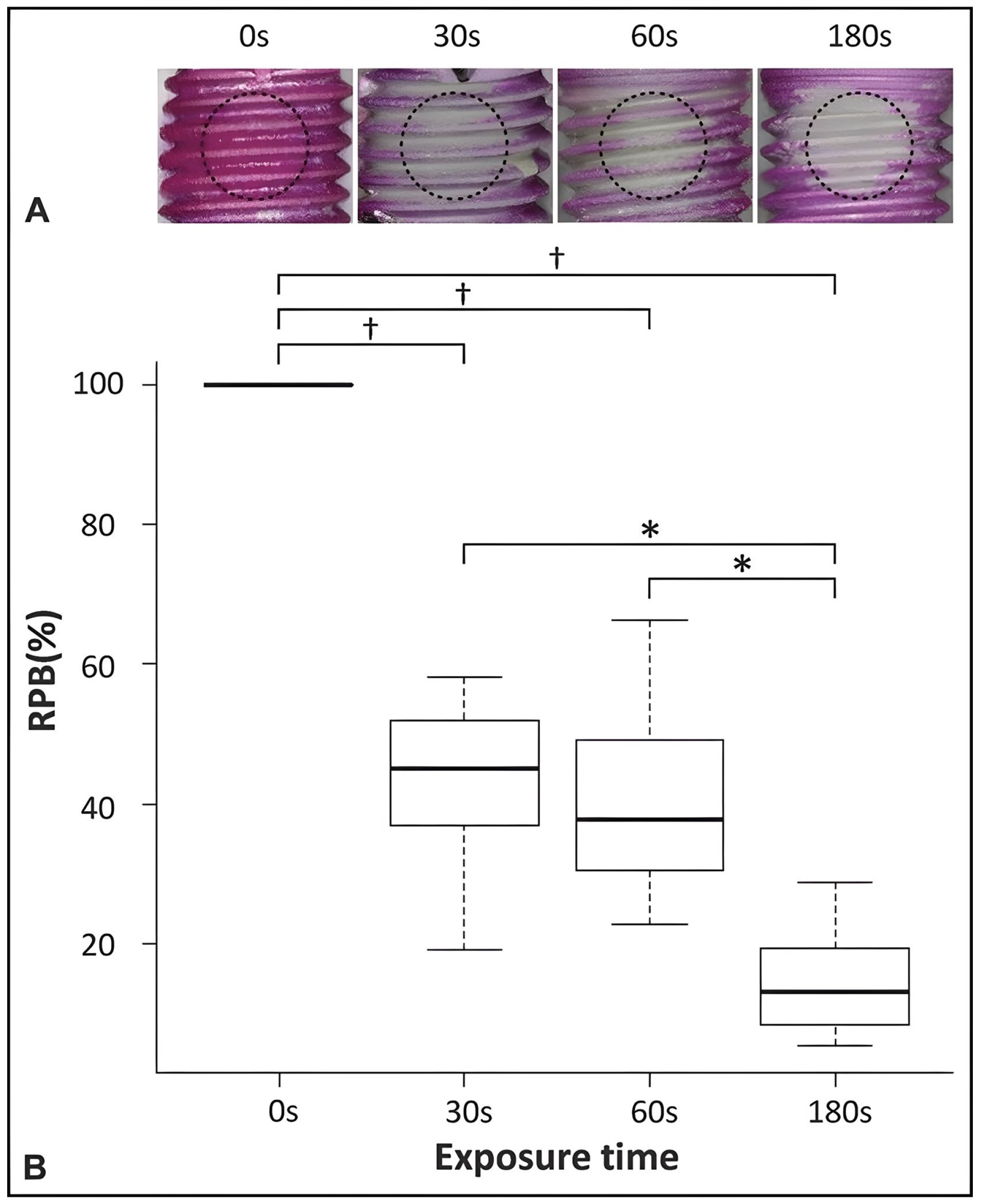
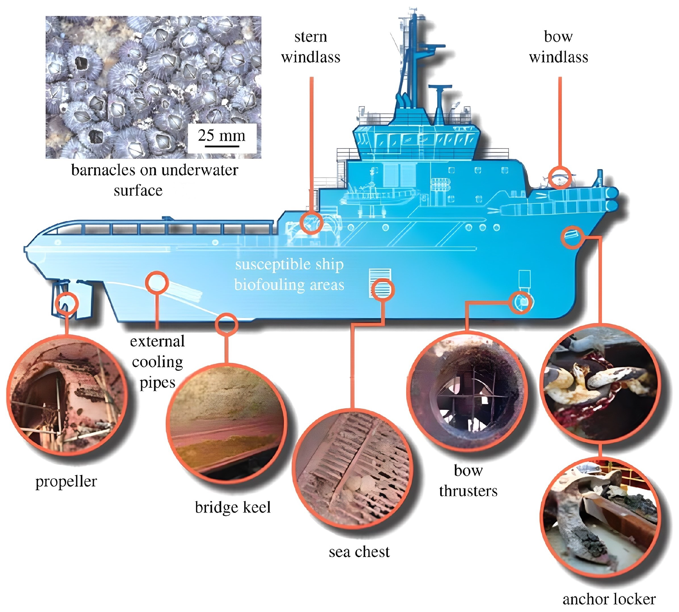
Song et al. [169] provide a comprehensive review and analysis of hull cleaning technology, detailing the typical fouling in dry docks (Figure 25) and various cleaning methods and equipment, including rotary brushes, high-pressure cavitating jet technology, ultrasonic technology, and laser cleaning technology. Among them, the high-pressure cavitating jet is a promising cleaning technology. Vickers et al. [170] proposed a model for erosion damage and cleaning efficiency of cavitation cleaning jets, which is deemed helpful for understanding the growing body of experimental data on cavitation cleaning jets. Yamada et al. [171] utilized cavitating jets for biofilm removal from the surface of implant screws, finding that cavitating jets can reduce residual biofilm (Figure 26), particularly in the roots, which are challenging to clean with conventional mechanical equipment. Although the volume of water used by the jets requires further optimization, this approach certainly broadens the application of cavitating jets in the cleaning domain.

3.5. Application in Biological Treatment and Waste Treatment

Due to bubble collapse, an extreme environment with high temperatures of 1000 to 10,000 K, high pressures of 100 to 5000 bar, and high-speed microjets reaching 102 m/s can be created [174]. In this environment, highly reactive radicals such as HO, H, HOO, HO2, and H2O2 are generated, facilitating degradation reactions. Therefore, hydrodynamic cavitation is regarded as an effective method for removing pollutants from wastewater.
The degradation of pollutants is typically explained as a result of the physical and chemical effects induced by bubble collapse. Extensive research has demonstrated that the effectiveness of cavitation in wastewater treatment arises from mechanical effects (e.g., shear stress), chemical effects (e.g., free radicals), and thermal effects (e.g., hot spots) caused by bubble collapse. The intense shear stresses generated during bubble rupture can cleave carbon–carbon bonds, resulting in the decomposition of organic macromolecules into smaller organic compounds [175]. Additionally, the rapid contraction of the bubble radius can create local hot spots. Under high-temperature conditions at the gas or gas–liquid interface within the bubble, organic molecules can decompose directly into inorganic or low molecular weight organic compounds during bubble rupture. This process occurs in solution and resembles a combustion-like reaction known as liquid-phase combustion. Simultaneously, water molecules trapped within the bubble dissociate into free radicals [176], which drive oxidation reactions at the gas–liquid interface or within the bulk liquid. The specific degradation pathway varies depending on the pollutant’s characteristics. For instance, rhodamine B, due to its low vapor pressure, is degraded by hydroxyl radicals either at the bubble interface or in the solution [177]. In the presence of hydroxyl radicals, the polyaromatic ring is initially cleaved from the chromophore and subsequently broken down [178,179]. The degradation of Red K-2B primarily results from the cleavage of the molecule’s conjugated structure, with the aromatic group only partially degraded [180]. In chitosan degradation, the chemical structure of the chitosan remains largely intact, with the reaction causing only the cleavage of the β-(1,4)-glycosidic bond [181].
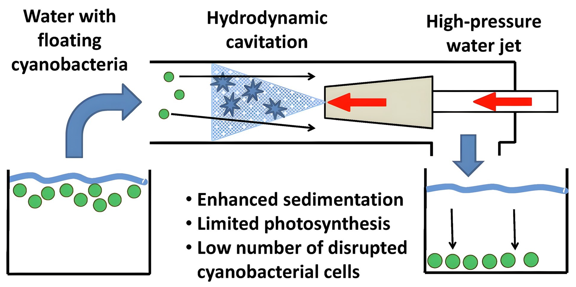
In the area of waste treatment, Zezulka et al. [182] found that hydrodynamic cavitation (HC) could disintegrate macrocolonies, enhance biomass deposition in cyanobacterial cell suspensions, and inhibit cyanobacterial photosynthesis (Figure 27). The number of cyanobacterial cells in their treated CWS was consistently reduced over an extended period, effectively reducing contamination by organic compounds (particularly cyanide toxins) released from the cells. This approach also shows great promise for treating raw water contaminated with cyanobacteria such as *Microcystis aeruginosa*, as it causes limited direct damage to the cells, preventing cyanotoxins in the final product. Additionally, it can be applied to address antibiotic degradation, offering significant chemical oxygen demand (COD) reduction and enhanced economic benefits, with the vertical double cavitating jet impact identified as the most effective impact form [183]. The synergistic effect of advanced Fenton oxidation and a jet ring hydrodynamic cavitation system can also achieve high mineralization of OR2 (industrial wastewater containing azo dyes), which is an advanced oxidation process with low chemical intensity [184].
Additionally, experiments have demonstrated that HC pretreatment technology can effectively improve the solubility and biodegradability of activated sludge [185]. This technology can modify the structure of sludge flocs, disrupt certain bacteria, and significantly increase the release of intracellular organic components. Hydrodynamic cavitation (HC) treatment of sludge increases the concentration of readily degradable COD. Moreover, the rates of phosphorus release and uptake using HC-treated sludge as a carbon source are comparable to those achieved with conventional biodegradable carbon sources, such as acetic acid [186]. HC can also act as a pretreatment method for anaerobic digestion, enhancing biogas production [187].
Cavitating jets have further applications in food processing. The combination of cavitating jets with oxidation treatment has been shown to significantly impact the structure and emulsification properties of soybean isolate protein (SPI) in experiments, as illustrated in Figure 28. The high shear force of cavitating jet treatment reduces protein aggregate size, resulting in a more uniform distribution. Additionally, it enhances the ordered secondary structure ( α -helical and β -sheet content) of SPI, demonstrating the potential for industrial applications [188]. Cavitating jet technology can also enhance the structure and physicochemical properties of soybean residue protein (OP), creating new opportunities for further development and utilization [189]. It can also effectively modify the structural properties of dietary fiber, breaking intermolecular hydrogen bonds and crystal structures, and enhancing its water solubility index, water-holding capacity, oil-holding capacity, swelling capacity, and thickening power. On one hand, value-added components with potential health benefits and functional ingredients can be produced from soybean processing by-products, while on the other, this approach helps reduce waste and pollution [190]. Furthermore, Ramirez-Cadavid et al. [50] demonstrated that hydrodynamic cavitation (HC) reduces corn pulp particle size and enhances total sugar and ethanol yields, achieving a positive net energy balance under HC-simulated conditions in a commercial-scale dry mill ethanol plant. This process improved the efficiency of dry-milled corn ethanol production from both economic and environmental standpoints.

4. Conclusions

This paper briefly introduces the development process of cavitating jets, discusses their modes of occurrence, and their range of applications. The main findings are summarized as follows:
  • The study categorizes three primary methods for generating cavitating jets: central body, oscillatory, and shear cavitation. Central body cavitation uses a physical obstruction to create intense, localized cavitation, ideal for high-impact applications. Oscillatory cavitation leverages resonance to produce controlled bubble formation and collapse, suited for precision needs. Shear cavitation, driven by velocity gradients and boundary interactions, supports broad-area applications and continuous-flow processes. Each method’s unique characteristics—cavitation intensity, stability, and control—make them adaptable for specific industrial uses, underscoring the importance of tailored method selection for diverse operational requirements.
  • Cavitating jets show significant potential across industries, including surface treatment, pollutant removal, material processing, and energy extraction. The intense impact force of bubble collapse enables effective applications such as surface peening, pollutant breakdown, precision cutting, and hydraulic fracturing. Adjustable cavitation parameters allow these jets to address varying application demands, from enhancing surface durability to processing confined materials. The flexibility offered by cavitating jets, with tailored generation methods for specific needs, allows for targeted industrial use, fostering innovation and efficiency in both established and emerging fields.
  • Despite advancements, challenges limit cavitating jet technology’s full implementation. Achieving efficient cavitation under high-pressure and low-energy conditions remains difficult, particularly for applications requiring prolonged stability and consistent intensity. Central body cavitation struggles with maintaining stability over large areas, while shear cavitation faces concentration issues along boundary layers. Optimizing nozzle designs and integrating hybrid methods (e.g., ultrasonic or laser assistance) could enhance performance, though such integrations introduce complexity. Addressing these issues will be crucial for maximizing cavitating jets’ versatility and effectiveness across industrial applications.
Although the mentioned various cavitating jets have been developed and applied for decades, there remains space for further research on the cavitition mechnism and applications. Based on current research progress, the following personal insights are presented:
  • Further research should focus on optimizing nozzle designs that enhance cavitation efficiency under varying pressure conditions. Developing nozzles capable of maintaining cavitation at lower energy inputs, while still achieving high-impact forces, would broaden the applicability of cavitating jets across industries. Coaxial and multi-orifice designs, which improve stability and cavitation intensity, offer promising avenues. Experimentation with materials and structural configurations could lead to more durable and adaptable nozzles, addressing issues such as wear and efficiency loss in high-intensity applications. Such innovations are essential for expanding the use of cavitating jets in industrial settings.
  • Hybrid methods, such as combining cavitating jets with ultrasonic or laser assistance, present a significant potential to amplify cavitation effects for specialized applications. These hybrid approaches could enhance the precision and energy concentration of cavitation, making them suitable for areas like precision cleaning, biomedical treatments, and environmental remediation. Further studies should examine the optimal parameters for synchronization and energy distribution in hybrid systems. Additionally, research into the interactions between different energy sources and cavitation mechanisms will be vital for fully leveraging hybrid techniques’ advantages while minimizing operational complexity.
  • Advancing computational fluid dynamics (CFD) models to more accurately simulate cavitation dynamics is crucial for optimizing cavitating jet design and application. Enhanced modeling would enable precise control over cavitation parameters and predict performance in diverse operational conditions. Coupling these models with experimental validation can provide a robust framework for understanding cavitation behavior and refining jet designs accordingly. Future research should focus on creating models that incorporate variables such as fluid properties, nozzle geometry, and hybrid cavitation effects to predict outcomes with higher accuracy, ultimately streamlining the design and implementation of cavitating jet technologies.

Author Contributions

Conceptualization, H.Z. and D.L.; methodology, D.L. and W.L.; writing—original draft preparation, H.Z. and L.W.; writing—review and editing, D.L. and C.F.; project administration, D.L.; funding acquisition, D.L. All authors have read and agreed to the published version of the manuscript.

Funding

This research was funded by National Natural Science Foundation of China grant number 52175245.

Data Availability Statement

No new data were created or analyzed in this study. Data sharing is not applicable to this article.

Conflicts of Interest

The authors declare no conflicts of interest.

References

  1. Burrill, L.C. The phenomenon of cavitation. Int. Shipbuild. Prog. 1955, 2, 503–511. [Google Scholar] [CrossRef]
  2. Johnson, V.; Kohl, R.; Thiruvengadam, A.; Conn, A. Tunneling, fracturing, drilling and mining with high speed water jets utilizing cavitation damage. In Proceedings of the 1st International Symposium on Jet Cutting Technology, Bedford, UK, 1 October 1972; British Hydromechanics Research Association: Cranfield, UK, 1972; p. A3-37. [Google Scholar]
  3. Conn, A.; Rudy, S. Cutting coal with the CAVIJET cavitating water jet method. In Proceedings of the 3rd International Symposium on Jet Cutting Technology, Chicago, IL, USA, 11 May 1976; pp. 11–13. [Google Scholar]
  4. Senshen, P. Modern Research on the Mechanism of Cavitation. Adv. Mech. 1979, 23, 4. [Google Scholar]
  5. Cui, M.; Sun, J. Higher Education Textbook: High-Pressure Water Jet Technology; China Coal Industry Publishing House: Beijing, China, 1993. [Google Scholar]
  6. Johnson, V.; Lindenmuth, W.; Conn, A. Feasibility Study of Tuned-Resonator, Pulsating Cavitating Water Jet for Deep-Hole Drilling; Petroleum; Sandia National Lab. (SNL-NM): Albuquerque, NM, USA; Hydronautics, Inc.: Laurel, MD, USA, 1981. [Google Scholar]
  7. Johnson, V.; Conn, A.; Lindenmuth, W.; Chahine, G.; Frederick, G. Self-resonating cavitating jets. In Proceedings of the 6th International Symposium on Jet Cutting Technology, BHRA, Cranfield, UK, 6–8 April 1982; pp. 1–26. [Google Scholar]
  8. Lichtarowicz, A.; Sakkejha, M. Cutting with cavitating jets. In Proceedings of the 1st International Symposium on Jet Cutting Technology, BHRA, Coventry, UK, 5–7 April 1972; Paper G6. Volume 26. [Google Scholar]
  9. Tavoularis, S.; Remisz, J.; Hu, S. A Study of the Practicality of Cavitating Water Jets; Springer: Dordrecht, The Netherlands, 1992. [Google Scholar]
  10. Soyama, H. Introduction of Compressive Residual Stress Using a Cavitating Jet in Air. J. Eng. Mater. Technol. 2004, 126, 123–128. [Google Scholar] [CrossRef]
  11. Soyama, H. High-Speed Observation of a Cavitating Jet in Air. J. Fluids Eng. 2005, 127, 1095–1101. [Google Scholar] [CrossRef]
  12. Soyama, H. Improvement of fatigue strength by using cavitating jets in air and water. J. Mater. Sci. 2007, 42, 6638–6641. [Google Scholar] [CrossRef]
  13. Li, Z. Criteria and erosion mechanism of cavitation jet formation. Eng. Mech. 2007, 24, 185–188. (In Chinese) [Google Scholar]
  14. Plesset, M.S.; Chapman, R.B. Collapse of an initially spherical vapour cavity in the neighbourhood of a solid boundary. J. Fluid Mech. 1971, 47, 283–290. [Google Scholar] [CrossRef]
  15. Lauterborn, W.; Bolle, H. Experimental investigations of cavitation-bubble collapse in the neighbourhood of a solid boundary. J. Fluid Mech. 1975, 72, 391–399. [Google Scholar] [CrossRef]
  16. Tomita, Y.; Shima, A. Mechanisms of impulsive pressure generation and damage pit formation by bubble collapse. J. Fluid Mech. 1986, 169, 535–564. [Google Scholar] [CrossRef]
  17. Vogel, A.; Lauterborn, W.; Timm, R. Optical and acoustic investigations of the dynamics of laser-produced cavitation bubbles near a solid boundary. J. Fluid Mech. 1989, 206, 299–338. [Google Scholar] [CrossRef]
  18. Isselin, J.C.; Alloncle, A.P.; Autric, M. On laser induced single bubble near a solid boundary: Contribution to the understanding of erosion phenomena. J. Appl. Phys. 1998, 84, 5766–5771. [Google Scholar] [CrossRef]
  19. Dular, M.; Bachert, B.; Stoffel, B.; Širok, B. Relationship between cavitation structures and cavitation damage. Wear 2004, 257, 1176–1184. [Google Scholar] [CrossRef]
  20. Johnsen, E.; Colonius, T. Numerical simulations of non-spherical bubble collapse. J. Fluid Mech. 2009, 629, 231–262. [Google Scholar] [CrossRef] [PubMed]
  21. Jin, W. Cavitation generation and inhibition. I. Dominant mechanism of turbulent kinetic energy for cavitation evolution. AIP Adv. 2021, 11, 065028. [Google Scholar] [CrossRef]
  22. Fortes-Patella, R.; Challier, G.; Reboud, J.L.; Archer, A. Energy balance in cavitation erosion: From bubble collapse to indentation of material surface. J. Fluids Eng. 2013, 135, 011303. [Google Scholar] [CrossRef]
  23. Leighton, T.; Farhat, M.; Field, J.; Avellan, F. Cavitation luminescence from flow over a hydrofoil in a cavitation tunnel. J. Fluid Mech. 2003, 480, 43–60. [Google Scholar] [CrossRef]
  24. Lavigne, S. Measurement of the aggressivity of erosive cavitating flows by a technique of pit analysis. Application to a method of prediction of erosion. In Proceedings of the International Symposium on Cavitation, CAV’95, Deauville, France, 2–5 May 1995; pp. 241–248. [Google Scholar]
  25. Escaler, X.; Farhat, M.; Avellan, F.; Egusquiza, E. Cavitation erosion tests on a 2D hydrofoil using surface-mounted obstacles. Wear 2003, 254, 441–449. [Google Scholar] [CrossRef]
  26. Fujisawa, N.; Fujita, Y.; Yanagisawa, K.; Fujisawa, K.; Yamagata, T. Simultaneous observation of cavitation collapse and shock wave formation in cavitating jet. Exp. Therm. Fluid Sci. 2018, 94, 159–167. [Google Scholar] [CrossRef]
  27. Shima, A.; Takayama, K.; Tomita, Y.; Miura, N. An experimental study on effects of a solid wall on the motion of bubbles and shock waves in bubble collapse. Acta Acust. United Acust. 1981, 48, 293–301. [Google Scholar]
  28. Tsuda, Y.; Ueki, H.; Hirose, T.; Kimoto, H. Experimental study of the shock generation at the collapse of cavitation bubble. Bull. JSME 1982, 25, 1890–1897. [Google Scholar] [CrossRef]
  29. Arabnejad, M.H.; Svennberg, U.; Bensow, R.E. Numerical assessment of cavitation erosion risk using incompressible simulation of cavitating flows. Wear 2021, 464, 203529. [Google Scholar] [CrossRef]
  30. Liu, H.; Kang, C.; Zhang, W.; Zhang, T. Flow structures and cavitation in submerged waterjet at high jet pressure. Exp. Therm. Fluid Sci. 2017, 88, 504–512. [Google Scholar] [CrossRef]
  31. Peng, C.; Tian, S.; Li, G. Joint experiments of cavitation jet: High-speed visualization and erosion test. Ocean Eng. 2018, 149, 1–13. [Google Scholar] [CrossRef]
  32. Nishimura, S.; Takakuwa, O.; Soyama, H. Similarity law on shedding frequency of cavitation cloud induced by a cavitating jet. J. Fluid Sci. Technol. 2012, 7, 405–420. [Google Scholar] [CrossRef]
  33. Sato, K.; Taguchi, Y.; Hayashi, S. High speed observation of periodic cavity behavior in a convergent-divergent nozzle for cavitating water jet. J. Flow Control. Meas. Vis. 2013, 2013, 102–107. [Google Scholar] [CrossRef]
  34. Hutli, E.; Nedeljkovic, M.; Bonyár, A. Dynamic behaviour of cavitation clouds: Visualization and statistical analysis. J. Braz. Soc. Mech. Sci. Eng. 2019, 41, 281. [Google Scholar] [CrossRef]
  35. Wu, Q.; Wei, W.; Deng, B.; Jiang, P.; Li, D.; Zhang, M.; Fang, Z. Dynamic characteristics of the cavitation clouds of submerged Helmholtz self-sustained oscillation jets from high-speed photography. J. Mech. Sci. Technol. 2019, 33, 621–630. [Google Scholar] [CrossRef]
  36. Liu, B.; Pan, Y.; Ma, F. Pulse pressure loading and erosion pattern of cavitating jet. Eng. Appl. Comput. Fluid Mech. 2020, 14, 136–150. [Google Scholar] [CrossRef]
  37. Hutli, E.; Nedeljkovic, M.S.; Radovic, N.A.; Bonyar, A. The relation between the high speed submerged cavitating jet behaviour and the cavitation erosion process. Int. J. Multiph. Flow 2016, 83, 27–38. [Google Scholar] [CrossRef]
  38. Soyama, H. Enhancing the aggressive intensity of a cavitating jet by introducing a cavitator and a guide pipe. J. Fluid Sci. Technol. 2014, 9, JFST0001. [Google Scholar] [CrossRef]
  39. Mishra, A.; Yadav, H.; Djenidi, L.; Agrawal, A. Effect of pulsation on the wall jet flow in the near region of an impinging jet. Exp. Fluids 2021, 62, 157. [Google Scholar] [CrossRef]
  40. Soyama, H. Cavitating jet: A review. Appl. Sci. 2020, 10, 7280. [Google Scholar] [CrossRef]
  41. Zhu, R.; Zhu, H.; Zhang, X. Numerical investigation about the unsteady behavior of a free submerged cavitation jet using the SBES approach. Ocean Eng. 2023, 281, 115010. [Google Scholar] [CrossRef]
  42. Zhao, Y.; Wang, G.; Huang, B. A cavitation model for computations of unsteady cavitating flows. Acta Mech. Sin. 2016, 32, 273–283. [Google Scholar] [CrossRef]
  43. Soyama, H.; Lichtarowicz, A.; Momma, T. Vortex cavitation in a submerged jet. Am. Soc. Mech. Eng. Fluids Eng. Div. (Publ.) FED 1996, 236, 415–422. [Google Scholar]
  44. Kang, C.; Zhou, L.; Yang, M.; Wang, Y. Experiment Study on Cavitating Waterjet Induced by a Central Body in the Nozzle. J. Eng. Thermophys. 2013, 34, 2275–2278. (In Chinese) [Google Scholar]
  45. Liu, L.; Deng, S.; Guan, J.; Li, G.; Yao, S.; Jiang, Y. Numerical Simulation and Structural Optimization of New Central Body Nozzle Flow Field. Nat. Gas Oil 2019, 37, 106–111. (In Chinese) [Google Scholar]
  46. Liao, Z. Theoretical study and application of self-oscillating pulsed jet nozzle. High Press. Water Jet 1993, 1, 1–14. [Google Scholar]
  47. Wang, Y.; Zhu, C.; Li, F.; Yu, C.; Chen, S.; Wu, J. Processing characteristics and loading principle on micro blanking of cavitation jet. Int. J. Adv. Manuf. Technol. 2024, 133, 1317–1329. [Google Scholar] [CrossRef]
  48. Takakuwa, O.; Soyama, H. Preventing hydrogen embrittlement in stainless steel by means of compressive stress induced by cavitation peening. J. Eng. 2015, 2015, 106–109. [Google Scholar] [CrossRef]
  49. Feng, R. Ultrasound Cavitation and Ultrasound Medicine. Nat. J. 2004, 25, 35–38. (In Chinese) [Google Scholar]
  50. Ramirez-Cadavid, D.A.; Kozyuk, O.; Lyle, P.; Michel, F.C., Jr. Effects of hydrodynamic cavitation on dry mill corn ethanol production. Process Biochem. 2016, 51, 500–508. [Google Scholar] [CrossRef]
  51. Brujan, E.A.; Nahen, K.; Schmidt, P.; Vogel, A. Dynamics of laser-induced cavitation bubbles near an elastic boundary. J. Fluid Mech. 2001, 433, 251–281. [Google Scholar] [CrossRef]
  52. Zhang, J. Research on the Effect of Nozzle Structure on Water Jet Velocity and Cavitation Capacity. Ph.D. Thesis, China University of Petroleum (East China), Dongying, China, 2019. (In Chinese). [Google Scholar]
  53. Deng, S.; Liao, S.; Yu, Y.; Guan, J. Study on Numerical Simulation of Cavitation Water Jet Induced by Abnormal Central-body. Fluid Mach. 2017, 45, 21–25. (In Chinese) [Google Scholar]
  54. Yang, M.; Xiao, S.; Kang, C. Influence of Outlet Profile on Performance of Central-body Nozzle. Fluid Mach. 2011, 39, 13–19. (In Chinese) [Google Scholar]
  55. Yang, M.; Xiao, S.; Kang, C.; Wang, Y. Effect of Geometrical Parameters on Submerged Cavitation Jet Discharged from Profiled Central-body Nozzle. Chin. J. Mech. Eng. 2013, 26, 476–482. (In Chinese) [Google Scholar] [CrossRef]
  56. Johnson, V.E., Jr.; Chahine, G.L.; Lindenmuth, W.T.; Conn, A.F.; Frederick, G.S.; Giacchino, G.J., Jr. The development of structured cavitating jets for deep-hole bits. In Proceedings of the SPE Annual Technical Conference and Exhibition, New Orleans, LA, USA, 26–29 September 1982; p. SPE–11060. [Google Scholar]
  57. Wang, Z.; Shen, Z. Mathematical model and experimental study of the jet excited oscillator. J. Pet. Univ. 1989, 13, 22–30. [Google Scholar]
  58. Peng, K.; Tian, S.; Li, G. Bubble dynamics characteristics and influencing factors on the cavitation collapse intensity for self-resonating cavitating jets. Pet. Explor. Dev. 2018, 45, 343–350. [Google Scholar] [CrossRef]
  59. Chahine, G.; Johnson, V. Mechanics and applications of self-excited cavitating jets. In Proceedings of the International Symposium on Jets and Cavities, ASME, WAM, Miami Beach, FL, USA, 17–22 November 1985; pp. 21–33. [Google Scholar]
  60. Qu, Y.; Chen, S. Orthogonal experimental research on the structural parameters of a self-excited pulsed cavitation nozzle. Eur. J. Mech.-B/Fluids 2017, 65, 179–183. [Google Scholar] [CrossRef]
  61. Li, D.; Kang, Y.; Ding, X.; Wang, X.; Fang, Z. Effects of area discontinuity at nozzle inlet on the characteristics of high speed self-excited oscillation pulsed waterjets. Exp. Therm. Fluid Sci. 2016, 79, 254–265. [Google Scholar] [CrossRef]
  62. Zhang, J.; Zhang, B.; Liu, B.; Li, B. Investigation on the influence of the frequency of pulsed water jet on the rock-breaking effect. Powder Technol. 2024, 431, 119054. [Google Scholar] [CrossRef]
  63. Tomita, Y.; Sato, K. Pulsed jets driven by two interacting cavitation bubbles produced at different times. J. Fluid Mech. 2017, 819, 465–493. [Google Scholar] [CrossRef]
  64. Cai, T.; Pan, Y.; Ma, F.; Xu, P. Effects of organ-pipe chamber geometry on the frequency and erosion characteristics of the self-excited cavitating waterjet. Energies 2020, 13, 978. [Google Scholar] [CrossRef]
  65. Hlaváč, L.M. System of chambers for activation of modulation or pulsation in water jets. In Proceedings of the 2007 American WJTA Conference and Expo, Houston, TX, USA, 19–21 August 2007; pp. 19–21. [Google Scholar]
  66. Zuzana Šimonovská, M. Device to Create and Intensify Modulation of Liquid Flow Velocity. Patent 302595, 27 July 2011. [Google Scholar]
  67. Wang, X.; Li, Y.; Hu, Y.; Ding, X.; Xiang, M.; Li, D. An experimental study on the jet pressure performance of Organ–Helmholtz (OH), self-excited oscillating nozzles. Energies 2020, 13, 367. [Google Scholar] [CrossRef]
  68. Shi, D.; Xing, Y.; Wang, L.; Chen, Z. Numerical Simulation and Experimental Research of Cavitation Jets in Dual-Chamber Self-Excited Oscillating Pulsed Nozzles. Shock Vib. 2022, 2022, 1268288. [Google Scholar] [CrossRef]
  69. Wang, J.; Li, J.; Guan, K.; Ma, T. Experimental study on the effect of multi frequency pulse of self-excited nozzle. J. Eng. Thermos-Phys. 2013, 34, 458–461. [Google Scholar]
  70. Pan, Y.; Cai, T.; Ma, F.; Qiu, L.; Cui, L. Self-excited Frequency Estimation Model of Organ-pipe Waterjet under Confining Pressure. J. Mech. Eng. 2018, 54, 220–225. [Google Scholar] [CrossRef]
  71. Zhou, Y.; Wang, X. Effect of pulse duration and pulse repetition frequency of cavitation histotripsy on erosion at the surface of soft material. Ultrasonics 2018, 84, 296–309. [Google Scholar] [CrossRef]
  72. Suo, D.; Govind, B.; Zhang, S.; Jing, Y. Numerical investigation of the inertial cavitation threshold under multi-frequency ultrasound. Ultrason. Sonochem. 2018, 41, 419–426. [Google Scholar] [CrossRef]
  73. Soyama, H. Effect of nozzle geometry on a standard cavitation erosion test using a cavitating jet. Wear 2013, 297, 895–902. [Google Scholar] [CrossRef]
  74. Zhang, S.; Fu, B.; Sun, L. Investigation of the jet characteristics and pulse mechanism of self-excited oscillating pulsed jet nozzle. Processes 2021, 9, 1423. [Google Scholar] [CrossRef]
  75. Xiang, L.; Wei, X.; Chen, S. Experimental study on the frequency characteristics of self-excited pulsed cavitation jet. Eur. J. Mech./B Fluids 2020, 83, 66–72. [Google Scholar] [CrossRef]
  76. Thaker, A.H.; Madane, K.R.; Ranade, V.V. Influence of viscosity and device scale on pressure drop and cavitation inception: Vortex based cavitation devices. Chem. Eng. J. 2023, 474, 145943. [Google Scholar] [CrossRef]
  77. Zeng, Q.; An, H.; Ohl, C.D. Wall shear stress from jetting cavitation bubbles: Influence of the stand-off distance and liquid viscosity. J. Fluid Mech. 2022, 932, A14. [Google Scholar] [CrossRef]
  78. Iwai, Y.; Li, S. Cavitation erosion in waters having different surface tensions. Wear 2003, 254, 1–9. [Google Scholar] [CrossRef]
  79. Krothapalli, A.; Venkatakrishnan, L.; Lourenco, L.; Greska, B.; Elavarasan, R. Turbulence and noise suppression of a high-speed jet by water injection. J. Fluid Mech. 2003, 491, 131–159. [Google Scholar] [CrossRef]
  80. Hu, H.; Zheng, Y.; Qin, C. Comparison of Inconel 625 and Inconel 600 in Resistance to Cavitation Erosion and Jet Impingement Erosion. Nucl. Eng. Des. 2010, 240, 2721–2730. [Google Scholar] [CrossRef]
  81. Pan, Y.; Ma, F. Cavitation intensity and erosion pattern of a self-excited cavitating jet. J. Mater. Process. Tech. 2020, 282, 116668. [Google Scholar] [CrossRef]
  82. O’hern, T. An experimental investigation of turbulent shear flow cavitation. J. Fluid Mech. 1990, 215, 365–391. [Google Scholar] [CrossRef]
  83. Katz, J.; O’Hern, T.J. Cavitation in Large Scale Shear Flows. J. Fluids Eng. 1986, 108, 373–376. [Google Scholar] [CrossRef]
  84. Iyer, C.O.; Ceccio, S.L. The influence of developed cavitation on the flow of a turbulent shear layer. Phys. Fluids 2002, 14, 3414–3431. [Google Scholar] [CrossRef]
  85. Yang, Y.; Li, W.; Shi, W.; Zhang, W.; El-Emam, M.A. Numerical investigation of a high-pressure submerged jet using a cavitation model considering effects of shear stress. Processes 2019, 7, 541. [Google Scholar] [CrossRef]
  86. Soyama, H.; Kikuchi, T.; Nishikawa, M. Introduction of compressive residual stress into stainless steel by employing a cavitating jet in air. Surf. Coatings Technol. 2011, 205, 3167–3174. [Google Scholar] [CrossRef]
  87. Fan, C.X.; Li, D.; Kang, Y.; Zhang, H.T. Effect of low-speed waterjet pressure on the rock-breaking performance of unsubmerged cavitating abrasive waterjet. Pet. Sci. 2024, 21, 2638–2649. [Google Scholar] [CrossRef]
  88. Liu, H.; Cao, Z.; Xie, C.; Chen, G.; Li, D.; Wang, J. Research on erosion characteristics of a novel cavitation nozzle under nonsubmerged condition. Proc. Inst. Mech. Eng. Part C J. Mech. Eng. Sci. 2021, 235, 988–998. [Google Scholar] [CrossRef]
  89. Fujisawa, N.; Kikuchi, T.; Fujisawa, K.; Yamagata, T. Time-resolved observations of pit formation and cloud behavior in cavitating jet. Wear 2017, 386–387, 99–105. [Google Scholar] [CrossRef]
  90. Yang, Y.; Li, W.; Shi, W.; Zhou, L.; Zhang, W. Experimental study on the unsteady characteristics and the impact performance of a high-pressure submerged cavitation jet. Shock Vib. 2020, 2020, 1701843. [Google Scholar] [CrossRef]
  91. Chen, Y.; Hu, Y.; Zhang, S. Structure optimization of submerged water jet cavitating nozzle with a hybrid algorithm. Eng. Appl. Comput. Fluid Mech. 2019, 13, 591–608. [Google Scholar] [CrossRef]
  92. Luo, Y.; Zang, J.; Zheng, H. Flow Field and Gas Field Distribution of Non-Submerged Cavitation Water Jet Based on Dual-Nozzle with Concentric Configuration. Water 2023, 15, 2904. [Google Scholar] [CrossRef]
  93. Xu, K.; Wang, G.; Wang, L.; Yun, F.; Sun, W.; Wang, X.; Chen, X. CFD-based study of nozzle section geometry effects on the performance of an annular multi-nozzle jet pump. Processes 2020, 8, 133. [Google Scholar] [CrossRef]
  94. Dong, W.; Yao, L.; Luo, W. Numerical simulation of flow field of submerged angular cavitation nozzle. Appl. Sci. 2023, 13, 613. [Google Scholar] [CrossRef]
  95. Marcon, A.; Melkote, S.N.; Yoda, M. Effect of nozzle size scaling in co-flow water cavitation jet peening. J. Manuf. Process. 2018, 31, 372–381. [Google Scholar] [CrossRef]
  96. Yamamoto, T.; Komarov, S.V. Dynamic behavior of acoustic cavitation bubble originated from heterogeneous nucleation. J. Appl. Phys. 2020, 128, 044702. [Google Scholar] [CrossRef]
  97. Lv, Z.; Hou, R.; Zhang, Y.; Chen, X. Investigation on the effect of cavitation in ultrasonic-assisted AWJ. Int. J. Adv. Manuf. Technol. 2020, 106, 3823–3830. [Google Scholar] [CrossRef]
  98. Lv, Z.; Hou, R.; Wang, T.; Huang, C.; Zhu, H. Research on cavitation involved in ultrasonic-assisted abrasive waterjet machining. Int. J. Adv. Manuf. Technol. 2019, 101, 1879–1886. [Google Scholar] [CrossRef]
  99. Sun, X.; Xuan, X.; Ji, L.; Chen, S.; Liu, J.; Zhao, S.; Park, S.; Yoon, J.Y.; Om, A.S. A novel continuous hydrodynamic cavitation technology for the inactivation of pathogens in milk. Ultrason. Sonochem. 2021, 71, 105382. [Google Scholar]
  100. Jain, P.; Bhandari, V.M.; Balapure, K.; Jena, J.; Ranade, V.V.; Killedar, D.J. Hydrodynamic cavitation using vortex diode: An efficient approach for elimination of pathogenic bacteria from water. J. Environ. Manag. 2019, 242, 210–219. [Google Scholar] [CrossRef]
  101. Yusof, N.S.M.; Babgi, B.; Alghamdi, Y.; Aksu, M.; Madhavan, J.; Ashokkumar, M. Physical and chemical effects of acoustic cavitation in selected ultrasonic cleaning applications. Ultrason. Sonochem. 2016, 29, 568–576. [Google Scholar] [CrossRef]
  102. Bai, F.; Wang, L.; Yang, K.; He, Z.; Liu, C.; Twiefel, J. A novel inner surface enhancement method for holes utilizing ultrasonic cavitation. Ultrasonics 2021, 115, 106453. [Google Scholar] [CrossRef]
  103. Soyama, H.; Iga, Y. Laser cavitation peening: A review. Appl. Sci. 2023, 13, 6702. [Google Scholar] [CrossRef]
  104. Akhatov, I.; Lindau, O.; Topolnikov, A.; Mettin, R.; Vakhitova, N.; Lauterborn, W. Collapse and rebound of a laser-induced cavitation bubble. Phys. Fluids 2001, 13, 2805–2819. [Google Scholar] [CrossRef]
  105. Gu, J.; Luo, C.; Lu, Z.; Ma, P.; Xu, X.; Ren, X. Bubble dynamic evolution, material strengthening and chemical effect induced by laser cavitation peening. Ultrason. Sonochem. 2021, 72, 105441. [Google Scholar] [CrossRef] [PubMed]
  106. Zhang, Y.; Xie, X.; Zhang, Y.; Zhang, Y.; Du, X. Experimental study of influences of a particle on the collapsing dynamics of a laser-induced cavitation bubble near a solid wall. Exp. Therm. Fluid Sci. 2019, 105, 289–306. [Google Scholar] [CrossRef]
  107. Brujan, A.; Noda, T.; Ishigami, A.; Ogasawara, T.; Takahira, H. Dynamics of laser-induced cavitation bubbles near two perpendicular rigid walls. J. Fluid Mech. 2018, 841, 28–49. [Google Scholar] [CrossRef]
  108. Zhou, J.; Andersson, M. An analysis of surface breakup induced by laser generated cavitation bubbles in a turbulent liquid jet. Exp. Fluids 2020, 61, 242. [Google Scholar] [CrossRef]
  109. Benjamin, T.B.; Ellis, A.T. The collapse of cavitation bubbles and the pressures thereby produced against solid boundaries. Philos. Trans. R. Soc. Lond. Ser. A Math. Phys. Sci. 1966, 260, 221–240. [Google Scholar]
  110. van Wijngaarden, L. Mechanics of collapsing cavitation bubbles. Ultrason. Sonochem. 2016, 29, 524–527. [Google Scholar] [CrossRef]
  111. Soyama, H.; Kumagai, N.; Takakuwa, O.; Takeo, F. Suppression of Fatigue Crack Propagation of Duralumin by Cavitation Peening. J. Eng. 2015, 2014, 135–139. [Google Scholar] [CrossRef]
  112. Marcon, A.; Melkote, S.N.; Castle, J.; Sanders, D.G.; Yoda, M. Effect of jet velocity in co-flow water cavitation jet peening. Wear 2016, 360, 38–50. [Google Scholar] [CrossRef]
  113. Takakuwa, O.; Nakai, M.; Narita, K.; Niinomi, M.; Hasegawa, K.; Soyama, H. Enhancing the Durability of Spinal Implant Fixture Applications Made of Ti-6Al-4V ELI by Means of Cavitation Peening. Int. J. Fatigue 2016, 92, 360–367. [Google Scholar] [CrossRef]
  114. Latchoumi, T.; Balamurugan, K.; Dinesh, K.; Ezhilarasi, T. Particle swarm optimization approach for waterjet cavitation peening. Measurement 2019, 141, 184–189. [Google Scholar] [CrossRef]
  115. Soyama, H.; Takeo, F. Comparison between cavitation peening and shot peening for extending the fatigue life of a duralumin plate with a hole. J. Mater. Process. Technol. 2016, 227, 80–87. [Google Scholar] [CrossRef]
  116. Soyama, H. Comparison between Shot Peening, Cavitation Peening, and Laser Peening by Observation of Crack Initiation and Crack Growth in Stainless Steel. Met.-Open Access Metall. J. 2019, 10, 63. [Google Scholar] [CrossRef]
  117. Soyama, H. Comparison between the improvements made to the fatigue strength of stainless steel by cavitation peening, water jet peening, shot peening and laser peening. J. Mater. Process. Technol. 2019, 269, 65–78. [Google Scholar] [CrossRef]
  118. Ijiri, M.; Yoshimura, T. Evolution of surface to interior microstructure of SCM435 steel after ultra-high-temperature and ultra-high-pressure cavitation processing. J. Mater. Process. Technol. 2018, 251, 160–167. [Google Scholar] [CrossRef]
  119. Chen, F.; Du, J.; Huang, S. Fabrication of repairable anti-corrosive superhydrophobic surfaces with micro-nano structures by ultrasonic cavitation. Appl. Surf. Sci. 2021, 541, 148605. [Google Scholar] [CrossRef]
  120. Ijiri, M.; Okada, N.; Kanetou, S.; Yamamoto, M.; Nakagawa, D.; Tanaka, K.; Yoshimura, T. Thermal Stress Relaxation and High-Temperature Corrosion of Cr-Mo Steel Processed Using Multifunction Cavitation. Materials 2018, 11, 2291. [Google Scholar] [CrossRef]
  121. Ijiri, M.; Ogi, T.; Yoshimura, T. High-temperature corrosion behavior of high-temperature and high-pressure cavitation processed Cr–Mo steel surface. Heliyon 2020, 6, e04698. [Google Scholar] [CrossRef]
  122. Gu, J.; Luo, C.; Ma, P.; Xu, X.; Wu, Y.; Ren, X. Study on processing and strengthening mechanisms of mild steel subjected to laser cavitation peening. Appl. Surf. Sci. 2021, 562, 150242. [Google Scholar] [CrossRef]
  123. Ijiri, M.; Yoshimura, T. Improvement of corrosion resistance of low-alloy steels by resurfacing using multifunction cavitation in water. In IOP Conference Series: Materials Science and Engineering; IOP Publishing: Bristol, UK, 2018; Volume 307, p. 012040. [Google Scholar]
  124. Bai, F.; Wang, L.; Saalbach, K.; Twiefel, J. A novel ultrasonic cavitation peening approach assisted by water jet. Appl. Sci. 2018, 8, 2218. [Google Scholar] [CrossRef]
  125. Beaucamp, A.; Katsuura, T.; Takata, K. Process mechanism in ultrasonic cavitation assisted fluid jet polishing. CIRP Ann. 2018, 67, 361–364. [Google Scholar] [CrossRef]
  126. Ge, J.; Ren, Y.; Xu, X.; Li, C.; Li, Z.; Xiang, W. Numerical and experimental study on the ultrasonic-assisted soft abrasive flow polishing characteristics. Int. J. Adv. Manuf. Technol. 2021, 112, 3215–3233. [Google Scholar] [CrossRef]
  127. Chen, F.; Wang, H.; Yin, S.; Huang, S.; Tang, Q.; Luo, H. Cavitation water-suction polishing of metallic materials under negative-pressure effect. J. Mater. Process. Technol. 2019, 273, 116257. [Google Scholar] [CrossRef]
  128. Chen, F.; Wang, H.; Tang, Y.; Yin, S.; Huang, S.; Zhang, G. Novel Cavitation Fluid Jet Polishing Process Based on Negative Pressure Effects. Ultrason. Sonochem. 2018, 42, 339–346. [Google Scholar] [CrossRef] [PubMed]
  129. Ge, M.; Ji, S.; Tan, D.; Cao, H. Erosion analysis and experimental research of gas-liquid–solid soft abrasive flow polishing based on cavitation effects. Int. J. Adv. Manuf. Technol. 2021, 114, 3419–3436. [Google Scholar] [CrossRef]
  130. Beaucamp, A.; Katsuura, T.; Kawara, Z. A novel ultrasonic cavitation assisted fluid jet polishing system. Cirp Ann. 2017, 66, 301–304. [Google Scholar] [CrossRef]
  131. Hutli, E.; Nedeljkovic, M.; Bonyar, A. Controlled Modification of the Surface Morphology and Roughness of Stainless Steel 316 by a High Speed Submerged Cavitating Water Jet. Appl. Surf. Sci. 2018, 458, 293–304. [Google Scholar] [CrossRef]
  132. Lu, Z.; Gu, J.; Zhang, P. Investigation on laser cavitation micro-forming process: Deformation behavior of 1060 aluminum foil and bubble evolution in a gap. J. Manuf. Process. 2021, 67, 619–627. [Google Scholar] [CrossRef]
  133. Li, F.; Fan, H.; Guo, Y.; Chen, Z.; Wang, X.; Li, R.; Liu, H.; Wang, Y. Water-Jet cavitation shock bulging as novel microforming technique. Chin. J. Mech. Eng. 2021, 34, 4. [Google Scholar] [CrossRef]
  134. Li, F.; He, P.; Chen, Z.; Chen, S.; Guo, J.; Xue, S.; Guo, Y.; Wang, Y. Water-jet cavitation shocking as a novel array micro-forming technique. Proc. Inst. Mech. Eng. Part B J. Eng. Manuf. 2021, 235, 987–994. [Google Scholar] [CrossRef]
  135. Whipple, K.X.; Hancock, G.S.; Anderson, R.S. River incision into bedrock: Mechanics and relative efficacy of plucking, abrasion, and cavitation. Geol. Soc. Am. Bull. 2000, 112, 490–503. [Google Scholar] [CrossRef]
  136. Jurewicz, E.; Gireń, B.; Steller, J. Cavitation erosion–a possible cause of the mass loss within thrust zones in the Tatra Mts., Poland. Acta Geol. Pol. 2007, 57, 305–323. [Google Scholar]
  137. Lopez-Sanchez, M.A.; Llana-Fúnez, S. A cavitation-seal mechanism for ultramylonite formation in quartzofeldspathic rocks within the semi-brittle field (Vivero fault, NW Spain). Tectonophysics 2018, 745, 132–153. [Google Scholar] [CrossRef]
  138. Patehebieke, Y.; Zhao, Z.R.; Wang, S.; Xu, H.X.; Chen, Q.Q.; Wang, X. Cavitation as a plausible driving force for the prebiotic formation of N9 purine nucleosides. Cell Rep. Phys. Sci. 2021, 2, 100375. [Google Scholar] [CrossRef]
  139. Su, H.; Zhou, W. Mechanism of accelerated dissolution of mineral crystals by cavitation erosion. Acta Geochim. 2020, 39, 11–42. [Google Scholar] [CrossRef]
  140. Carling, P.A.; Perillo, M.; Best, J.; Garcia, M.H. The bubble bursts for cavitation in natural rivers: Laboratory experiments reveal minor role in bedrock erosion. Earth Surf. Process. Landforms 2017, 42, 1308–1316. [Google Scholar] [CrossRef]
  141. Chi, P.; Chaoyue, Z.; Qinfeng, L.; Shilong, Z.; Yu, S.; Hairui, L.; Jianhong, F. Erosion characteristics and failure mechanism of reservoir rocks under the synergistic effect of ultrasonic cavitation and micro-abrasives. Adv. Powder Technol. 2021, 32, 4391–4407. [Google Scholar] [CrossRef]
  142. Chen, Y.; Fang, Z.; Xiong, T.; Hou, W.; Zhang, Z.; Shi, R. An experimental study on the erosion of sandstone by self-excited oscillation cavitation waterjet in submerged environment. Ocean Eng. 2023, 279, 114546. [Google Scholar] [CrossRef]
  143. Apte, D.; Ge, M.; Coutier-Delgosha, O. Numerical investigation of a cavitating nozzle for jetting and rock erosion based on different turbulence models. Geoenergy Sci. Eng. 2023, 231, 212300. [Google Scholar] [CrossRef]
  144. Guo, C.; Lin, B.; Yao, H.; Yang, K.; Zhu, C. Characteristics of breaking coal-rock by submerged jet and its application on enhanced coal bed methane recovery. Energy Sources Part A Recover. Util. Environ. Eff. 2020, 42, 2249–2260. [Google Scholar] [CrossRef]
  145. Jasper, S.; Gradzki, D.; Bracke, R.; Hussong, J.; Petermann, M.; Lindken, R. Nozzle Cavitation and Rock Erosion Experiments Reveal Insight into the Jet Drilling Process. Chem. Ing. Tech. 2021, 93, 1610–1618. [Google Scholar] [CrossRef]
  146. Fan, C.; Zhang, H.; Kang, Y.; Shi, H.; Li, D. Rock breaking performance of the newly proposed unsubmerged cavitating abrasive waterjet. Int. J. Min. Sci. Technol. 2023, 33, 843–853. [Google Scholar] [CrossRef]
  147. Liang, Z.; Ma, Y.; Nie, Q.; Wang, X.; Zhou, T.; Guo, H.; Sun, X.; Jiang, L. Ultrasonic cavitation and vibration hybrid-assisted micro-drilling of stainless steel. Int. J. Adv. Manuf. Technol. 2019, 104, 3073–3082. [Google Scholar] [CrossRef]
  148. Tinne, N.; Schumacher, S.; Nuzzo, V.; Ripken, T.; Lubatschowski, H. Dynamic and interaction of fs-laser induced cavitation bubbles for analyzing the cutting effect. In Proceedings of the European Conference on Biomedical Optics, Munich, Germany, 14–18 June 2009; Optica Publishing Group: Washington, DC, USA, 2009; p. 7373_0L. [Google Scholar]
  149. Arba-Mosquera, S.; Naubereit, P.; Sobutas, S.; Verma, S. Analytical optimization of the cutting efficiency for generic cavitation bubbles. Biomed. Opt. Express 2021, 12, 3819–3835. [Google Scholar] [CrossRef] [PubMed]
  150. Xiong, J.; Cai, J.; Kang, Y.; Wang, X.; Lai, Q.; Li, D. Generation of effective pulsed waterjets by ultrasonic nozzle used for energy exploration. Energy 2024, 294, 130868. [Google Scholar] [CrossRef]
  151. Al-Jubori, A.; Johnston, S.; Boyer, C.; Lambert, S.; Bustos, O.; Pashin, J.; Wray, A. Coalbed methane: Clean energy for the world. Oilfield Rev. 2009, 21, 4–13. [Google Scholar]
  152. Ji, X.; Song, D.; Zhao, H.; Li, Y.; He, K. Experimental analysis of pore and permeability characteristics of coal by low-field NMR. Appl. Sci. 2018, 8, 1374. [Google Scholar] [CrossRef]
  153. Wang, H.; Xia, B.; Lu, Y.; Ge, Z.; Tang, J. Experimental study on sonic vibrating effects of cavitation water jets and its promotion effects on coalbed methane desorption. Fuel 2016, 185, 468–477. [Google Scholar] [CrossRef]
  154. Zhang, H.; Cheng, Y.; Liu, Q.; Yuan, L.; Dong, J.; Wang, L.; Qi, Y.; Wang, W. A novel in-seam borehole hydraulic flushing gas extraction technology in the heading face: Enhanced permeability mechanism, gas flow characteristics, and application. J. Nat. Gas Sci. Eng. 2017, 46, 498–514. [Google Scholar] [CrossRef]
  155. Zou, Q.; Lin, B. Fluid–solid coupling characteristics of gas-bearing coal subject to hydraulic slotting: An experimental investigation. Energy Fuels 2018, 32, 1047–1060. [Google Scholar] [CrossRef]
  156. Zhang, Y.; Zhao, K.; Wu, X.; Tian, S.; Shi, H.; Wang, W.; Zhang, P. An innovative experimental apparatus for the analysis of natural gas hydrate erosion process using cavitating jet. Rev. Sci. Instrum. 2020, 91, 095107. [Google Scholar] [CrossRef] [PubMed]
  157. Huang, H.; Zhang, Y.; Wu, X.; Hui, C.; Tan, Y.; Li, G. Study on the Decomposition of Natural Gas Hydrate Induced by Cavitation Damage. In Proceedings of the ARMA US Rock Mechanics/Geomechanics Symposium, Atlanta, GA, USA, 25–28 June 2023; p. ARMA-2023-0366. [Google Scholar]
  158. Wu, X.Y.; Zhang, Y.Q.; Xu, Z.Q.; Zhao, S.; Li, G.S.; Tian, S.C.; Tan, Y.W.; Peng, K.W. Structure optimization of the organ-pipe cavitating nozzle and its erosion ability test on hydrate-bearing sediments. Pet. Sci. 2023, 20, 1104–1118. [Google Scholar] [CrossRef]
  159. Song, X.; Li, G.; Yuan, J.; Tian, Z.; Shen, R.; Yuan, G.; Huang, Z. Mechanisms and field test of solution mining by self-resonating cavitating water jets. Pet. Sci. 2010, 7, 385–389. [Google Scholar] [CrossRef]
  160. Vijay, M. Comparison of the performance of high-speed abrasive-entrained, cavitating and plain water jets for selective mining applications. Int. J. Surf. Mining Reclam. Environ. 1992, 6, 1–9. [Google Scholar] [CrossRef]
  161. Fang, Z.; Gao, X.; Tao, X.; Li, D.; Zhang, M.; Xiong, T.; Jiang, P. Impact performance of Helmholtz self-excited oscillation waterjets used for underground mining. Appl. Sci. 2019, 9, 3235. [Google Scholar] [CrossRef]
  162. Prosperetti, A. Bubbles. Phys. Fluids 2004, 16, 1852. [Google Scholar] [CrossRef]
  163. Yao, Y.; Wang, H.; Fang, Z.; Li, D.; Wang, B. Experimental study and prediction model of the cleaning effect induced by self-resonating cavitating waterjet. J. Mech. Sci. Technol. 2022, 36, 5097–5106. [Google Scholar] [CrossRef]
  164. Liu, C.; Liu, G.; Yan, Z. Study on Cleaning Effect of Different Water Flows on the Pulsed Cavitating Jet Nozzle. Shock Vib. 2019, 2019, 1496594. [Google Scholar] [CrossRef]
  165. Song, W. Laser-induced cavitation bubbles for cleaning of solid surfaces. J. Appl. Phys. 2004, 95, 2952–2956. [Google Scholar] [CrossRef]
  166. Ohl, C.; Arora, M.; Dijkink, R.; Janve, V.; Lohse, D. Surface cleaning from laser-induced cavitation bubbles. Appl. Phys. Lett. 2006, 89, 074102. [Google Scholar] [CrossRef]
  167. Ralys, A.; Mokin, V. Numerical Simulation of a Cavitating Pulsating Water Jet Used for Removing Contaminants from Metal Surfaces. Trans. FAMENA 2020, 43, 69–80. [Google Scholar] [CrossRef]
  168. Verhaagen, B.; Rivas, D.F. Measuring cavitation and its cleaning effect. Ultrason. Sonochem. 2016, 29, 619–628. [Google Scholar] [CrossRef] [PubMed]
  169. Song, C.; Cui, W. Review of Underwater Ship Hull Cleaning Technologies. J. Mar. Sci. Appl. 2020, 19, 415–429. [Google Scholar] [CrossRef]
  170. Vickers, G.; Houlston, R. Modelling the erosion efficiency of cavitation cleaning jets. Appl. Sci. Res. 1983, 40, 377–391. [Google Scholar] [CrossRef]
  171. Yamada, J.; Takiguchi, T.; Saito, A.; Odanaka, H.; Soyama, H.; Yamamoto, M. Removal of Oral Biofilm on an Implant Fixture by a Cavitating Jet. Implant Dent. 2017, 26, 904. [Google Scholar] [CrossRef]
  172. Bixler, G.D.; Bhushan, B. Biofouling: Lessons from nature. Philos. Trans. R. Soc. A Math. Phys. Eng. Sci. 2012, 370, 2381–2417. [Google Scholar] [CrossRef]
  173. Kwon, G.S.; Kataoka, K. Block copolymer micelles as long-circulating drug vehicles. Adv. Drug Deliv. Rev. 1995, 16, 295–309. [Google Scholar] [CrossRef]
  174. Franc, J.P.; Michel, J.M. Fundamentals of Cavitation; Springer Science & Business Media: Dordrecht, The Netherlands, 2006; Volume 76. [Google Scholar]
  175. Doulah, M. Mechanism of disintegration of biological cells in ultrasonic cavitation. Biotechnol. Bioeng. 1977, 19, 649–660. [Google Scholar] [CrossRef]
  176. Storey, B.D.; Szeri, A.J. Water vapour, sonoluminescence and sonochemistry. Proc. R. Soc. London. Ser. A Math. Phys. Eng. Sci. 2000, 456, 1685–1709. [Google Scholar] [CrossRef]
  177. Wang, X.; Yao, Z.; Wang, J.; Guo, W.; Li, G. Degradation of reactive brilliant red in aqueous solution by ultrasonic cavitation. Ultrason. Sonochem. 2008, 15, 43–48. [Google Scholar] [CrossRef]
  178. Sivakumar, M.; Senthilkumar, P.; Majumdar, S.; Pandit, A.B. Ultrasound mediated alkaline hydrolysis of methyl benzoate—Reinvestigation with crucial parameters. Ultrason. Sonochem. 2002, 9, 25–30. [Google Scholar] [CrossRef] [PubMed]
  179. Mishra, K.P.; Gogate, P.R. Intensification of degradation of Rhodamine B using hydrodynamic cavitation in the presence of additives. Sep. Purif. Technol. 2010, 75, 385–391. [Google Scholar] [CrossRef]
  180. Wang, J.; Cao, Y.; Sun, B.; Wang, C.; Mo, Y. Effect of ultrasound on the activity of alliinase from fresh garlic. Ultrason. Sonochem. 2011, 18, 534–540. [Google Scholar] [CrossRef] [PubMed]
  181. Huang, Y.; Wu, Y.; Huang, W.; Yang, F. Degradation of chitosan by hydrodynamic cavitation. Polym. Degrad. Stab. 2013, 98, 37–43. [Google Scholar] [CrossRef]
  182. Zezulka, S.; Marsalkova, E.; Pochylý, F.; Rudolf, P.; Hudec, M.; Maršálek, B. High-pressure jet-induced hydrodynamic cavitation as a pre-treatment step for avoiding cyanobacterial contamination during water purification. J. Environ. Manag. 2020, 255, 109862. [Google Scholar] [CrossRef]
  183. Tao, Y.; Cai, J.; Huai, X.; Liu, B. A novel antibiotic wastewater degradation technique combining cavitating jets impingement with multiple synergetic methods. Ultrason. Sonochem. 2018, 44, 36–44. [Google Scholar] [CrossRef]
  184. Badmus, K.O.; Irakoze, N.; Adeniyi, O.R.; Petrik, L. Synergistic Advance Fenton Oxidation and Hydrodynamic Cavitation treatment of persistent organic dyes in textile wastewater. J. Environ. Chem. Eng. 2019, 8, 103521. [Google Scholar] [CrossRef]
  185. Mancuso, G.; Langone, M.; Andreottola, G. A swirling jet-induced cavitation to increase activated sludge solubilisation and aerobic sludge biodegradability. Ultrason. Sonochem. 2017, 35, 489–501. [Google Scholar] [CrossRef]
  186. Ferrentino, R.; Andreottola, G. Investigation of sludge solubilization and phosphorous release in anaerobic side-stream reactor with a low pressure swirling jet hydrodynamic cavitation treatment. J. Environ. Chem. Eng. 2020, 8, 104389. [Google Scholar] [CrossRef]
  187. Patil, P.N.; Gogate, P.R.; Csoka, L.; Dregelyi-Kiss, A.; Horvath, M. Intensification of biogas production using pretreatment based on hydrodynamic cavitation. Ultrason. Sonochem. 2016, 30, 79–86. [Google Scholar] [CrossRef]
  188. He, M.; Wu, C.; Li, L.; Zheng, L.; Tian, T.; Jiang, L.; Li, Y.; Teng, F. Effects of Cavitation Jet Treatment on the Structure and Emulsification Properties of Oxidized Soy Protein Isolate. Foods 2021, 10, 2. [Google Scholar] [CrossRef] [PubMed]
  189. Wu, C.; He, M.; Zheng, L.; Tian, T.; Teng, F.; Li, Y. Effect of cavitation jets on the physicochemical properties and structural characteristics of the okara protein. J. Food Sci. 2021, 86, 4566–4576. [Google Scholar] [CrossRef] [PubMed]
  190. Wu, C.; Teng, F.; McClements, D.J.; Zhang, S.; Li, Y.; Wang, Z. Effect of cavitation jet processing on the physicochemical properties and structural characteristics of okara dietary fiber. Food Res. Int. 2020, 134, 109251. [Google Scholar] [CrossRef] [PubMed]
Figure 1. Time pulse signals and shock wave formation in cavitating jet impinging on walls [26].
Energies 17 05902 g001
Figure 2. A comparison of cavitation cloud dynamics using experimental and numerical methods. Images are taken at 0.2 ms intervals. (a) High-speed experimental photograph; (b) cavitation cloud visualized as an iso-surface at a v = 0.5 , u j is the injection velocity, u f is the velocities of the cavitation cloud front; (c) cavitation cloud illustrated through a contour map of a v [41].
Energies 17 05902 g002
Figure 5. Schematic illustration of a Helmholtz oscillator and its operating principles [61].
Energies 17 05902 g005
Figure 6. Schematic representation of the organ-pipe nozzle geometry and the generation process of a self-excited cavitating jet [64].
Energies 17 05902 g006
Figure 7. Diagram of the internal structure of the cavitation nozzles. (a) Helmholtz + organ pipe; (b) Helmholtz + Helmholtz; (c) organ pipe + organ pipe.
Energies 17 05902 g007
Figure 8. Schematic diagram of the self-excited pulse nozzle device. Components: 1—suction nozzle, 2—oscillation chamber, 3—collision object, 4—cylinder, 5—discharge nozzle [75].
Energies 17 05902 g008
Figure 9. Various erosion patterns and their corresponding cross-sectional surface profiles are illustrated as follows: (a) Pattern A, σ = 0.05 , s / d = 5 ; (b) Pattern B, σ = 0.05 , s / d = 9.5 ; (c) Pattern C, σ = 0.11 , s / d = 5 [81].
Energies 17 05902 g009
Figure 10. Distribution of vapor volume fraction in the submerged cavitating jet: (a) ZGB model; (b) current cavitation model, and (c) experimental image [85].
Energies 17 05902 g010
Figure 11. Geometry of the nozzle for a cavitating jet in air [86].
Energies 17 05902 g011
Figure 12. Aspect of the cavitating jet in air changing with time ( P H = 30 MPa, P L = 0.05 MPa, d H O = 16 mm) [86].
Energies 17 05902 g012
Figure 13. Cloud view of nozzle vapor phase distribution under submerged and non-submerged conditions: (a) Submerged condition; (b) non-submerged condition [88].
Energies 17 05902 g013
Figure 14. Bubble shapes following liquid jet formation for a 40 × 80 μm crack under pressure amplitudes of (a) 0.5 atm and (b) 0.8 atm [96].
Energies 17 05902 g014
Figure 15. Enhancement of fatigue strength through different peening techniques [117].
Energies 17 05902 g015
Figure 16. Equipment used for surface machining through water jet cavitation combined with ultrasonication [123].
Energies 17 05902 g016
Figure 17. Surface topography: (a) Before polishing, and after polishing for (b) 10 min, (c) 60 min, and (d) 150 min, at an outlet pressure of −75 kPa [128].
Energies 17 05902 g017
Figure 18. Abridged general view of CGLSP polishing tool. 1, abrasive flow pump; 2, workpiece; 3, tank; 4, CGLSP polishing tool nozzle; 5, vacuum plate [129].
Energies 17 05902 g018
Figure 19. Schematic diagram of the mechanism of LCMF [132].
Energies 17 05902 g019
Figure 20. Schematic illustration of hybrid-assisted micro-drilling combining ultrasonic cavitation and vibration [147].
Energies 17 05902 g020
Figure 21. Cross-sectional metallographic diagram of the blanking forming process (parameters: incident pressure 20 MPa, target distance 120 mm, nozzle aperture 1.6 mm): (a) blanking in progress, (b) completed blanking [47].
Energies 17 05902 g021
Figure 22. Surface fracture characteristics following hydraulic slotting: (a) slot shapes, (b) average slot length under varying water jet pressures, and (c) relationship between sample rupture time and drilling angle [144].
Energies 17 05902 g022
Figure 23. Amplitude of axial pressure fluctuations in water jets emitted from the organ-pipe nozzle at varying ambient pressures [159].
Energies 17 05902 g023
Figure 24. The schematic diagram of wet laser cleaning system [165].
Energies 17 05902 g024
Figure 25. Typical fouling of ships caused by marine organisms [172,173].
Energies 17 05902 g025
Figure 26. (A) Optical images of the untreated fixture and treated fixtures following the application of the cavitating jet. (B) Time course of biofilm removal. * Significant difference observed ( p < 0.05 , Mann-Whitney U test). † Significant difference observed ( p < 0.05 , Wilcoxon signed-rank test) [171].
Energies 17 05902 g026
Figure 27. Hydrodynamic cavitation as a method for purifying cyanobacterial cell suspensions [182].
Energies 17 05902 g027
Figure 28. (A) Emulsification activity index (EAI) and (B) emulsion stability index (ESI) of SPI emulsions oxidized before and after cavitating jet treatment. Columns labeled with different letters (a–f) indicate significant differences ( p < 0.05 ) [188].
Energies 17 05902 g028
Table 1. Comparison of the features and application areas of different types of cavitating jet.
Cavitation MethodFeaturesApplications
Central Body Cavitation [44,45]
  • Medium cavitation strength
  • Simple structure, low cost
  • High requirements for fluid flow rate
  • Easy to operate and maintain, suitable for long-term operation
  • Oil-water separation, mineral flotation in energy exploration
  • Waste Treatment
Oscillatory Cavitation [46,47]
  • Medium cavitation strength
  • Adjustable oscillation frequency
  • Uniform bubble distribution, high mass transfer efficiency
  • Fluid adaptability, can be used in different media
  • Cleaning
  • Improving the surface performance of materials, as surface material strengthening
Shear Cavitation [48]
  • Medium cavitation strength
  • Efficient dispersion and homogenization of fluid particles
  • Adaptable to fluid viscosity
  • Surface material strengthening, surface material micro-forming
  • Cleaning
  • Mineral crushing, metal cutting
Ultrasonic Cavitation [49,50]
  • High cavitation strength
  • Precise control of cavitation location and intensity
  • Cleans tiny pores and surfaces
  • Efficient energy conversion for small area treatment
  • Treatment of precision surfaces and micro pores
  • Biological treatment
  • Surface polished, surface material micro-forming
Laser Induced Cavitation [51]
  • Extremely high cavitation strength
  • Instantaneous generation of high temperature and pressure
  • Precise positioning of the cavitation point
  • Complicated equipment, difficult to operate
  • High-precision local processing
  • Crushing and cutting
  • Surface material strengthening, surface material micro-forming
Table 2. The effect of different shaped center bodies on cavitating jet.
Nozzle DesignCavitation IntensityJet VelocityStability
Flat-HeadedHighModerateLow
ConicalModerateHighHigh
HemisphericalLowModerateHigh
Disclaimer/Publisher’s Note: The statements, opinions and data contained in all publications are solely those of the individual author(s) and contributor(s) and not of MDPI and/or the editor(s). MDPI and/or the editor(s) disclaim responsibility for any injury to people or property resulting from any ideas, methods, instructions or products referred to in the content.