
Experimental Assessment of Hydrodynamic Behavior in a Gravitational Vortex Turbine with Different Inlet Channel and Discharge Basin Configurations

 , , ,
, , ,  and
and 
Abstract
1. Introduction
2. Materials and Methods
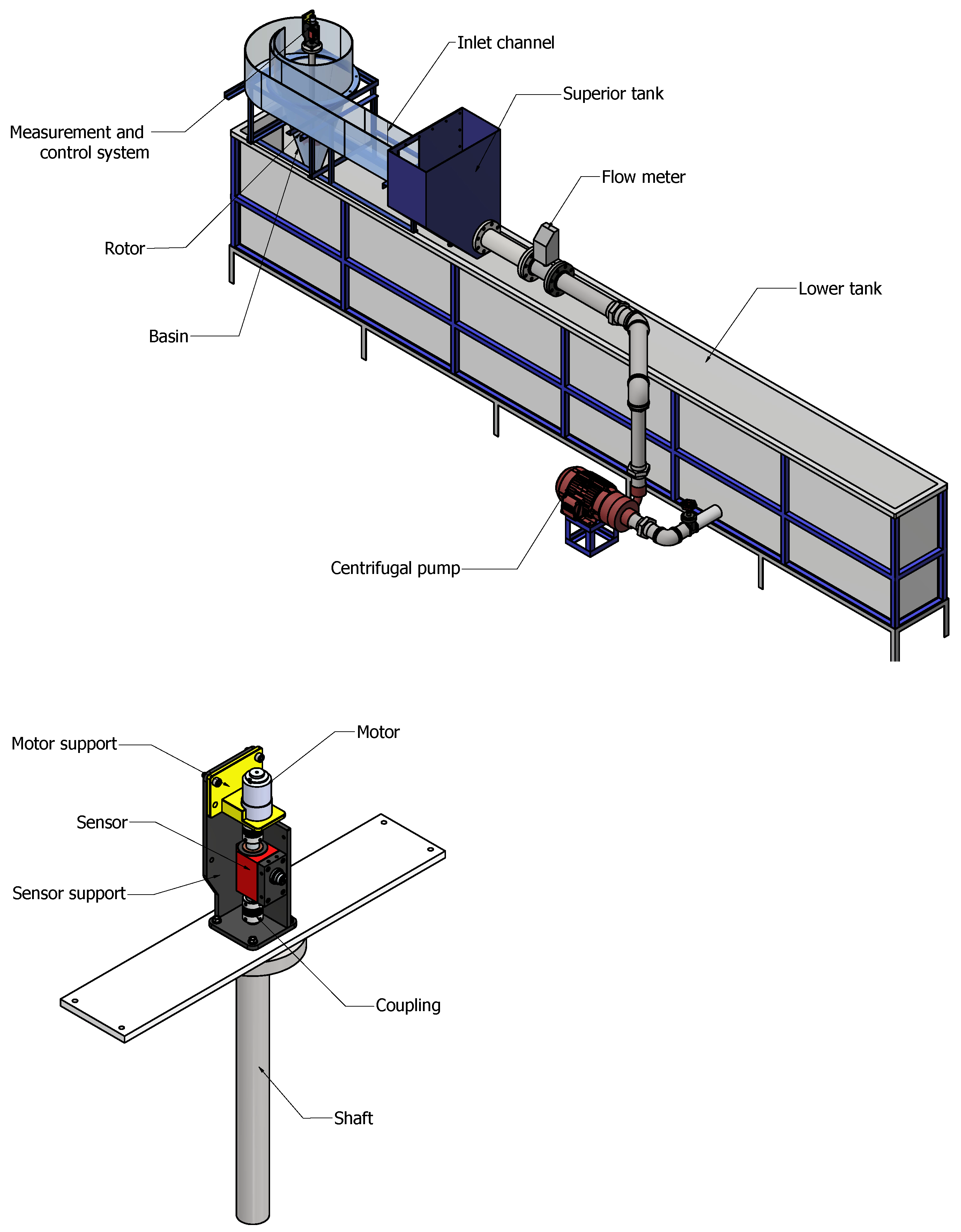
2.1. Experimental Setup
2.2. Data Repeatability
3. Results and Discussion
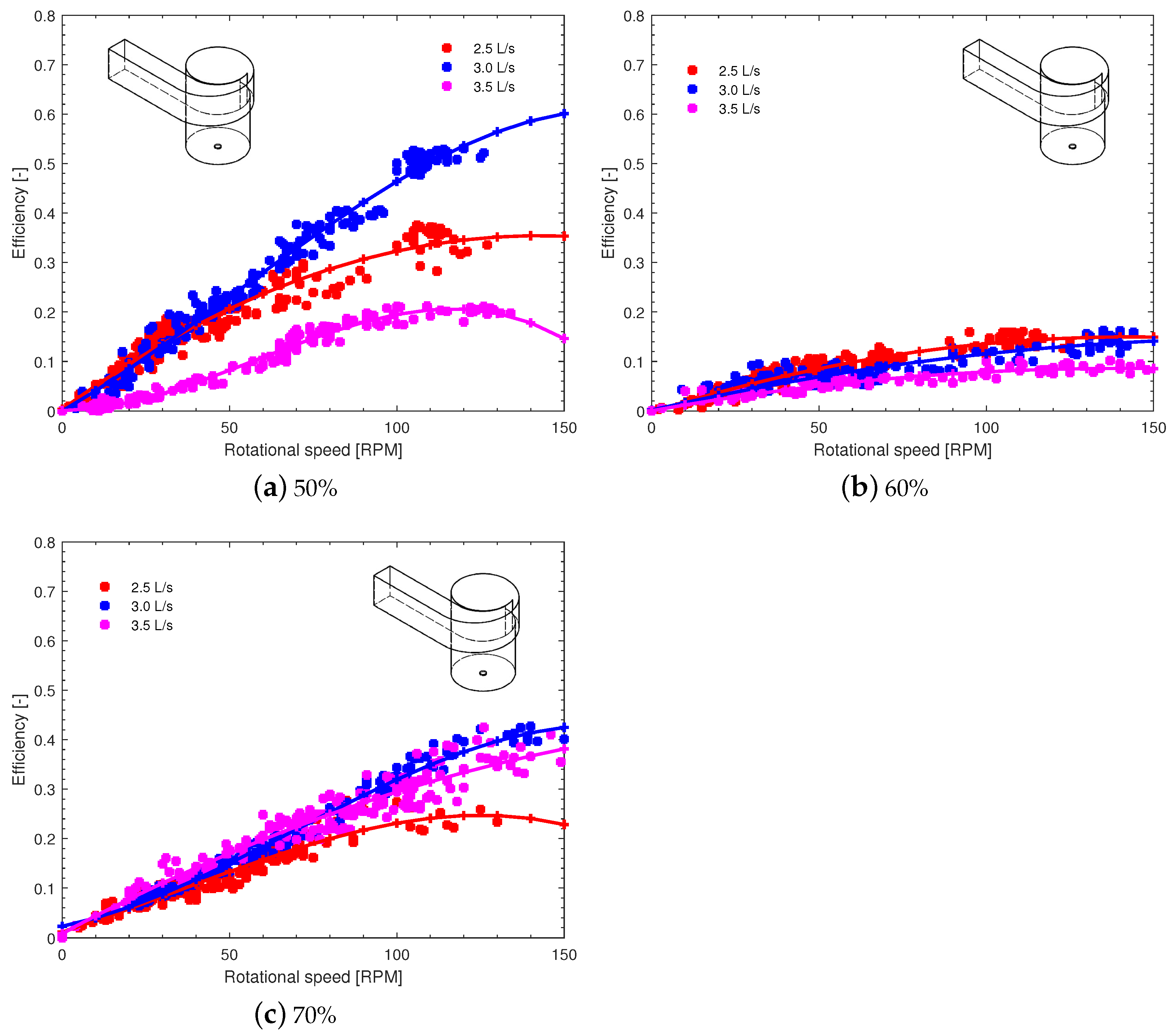
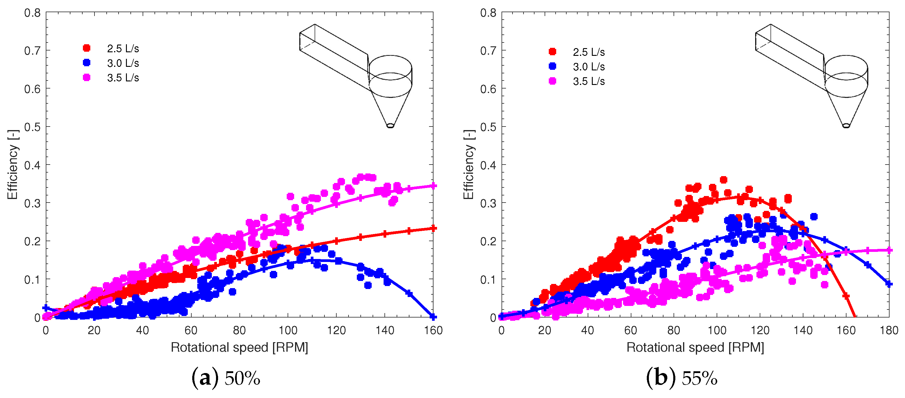
3.1. Model 1
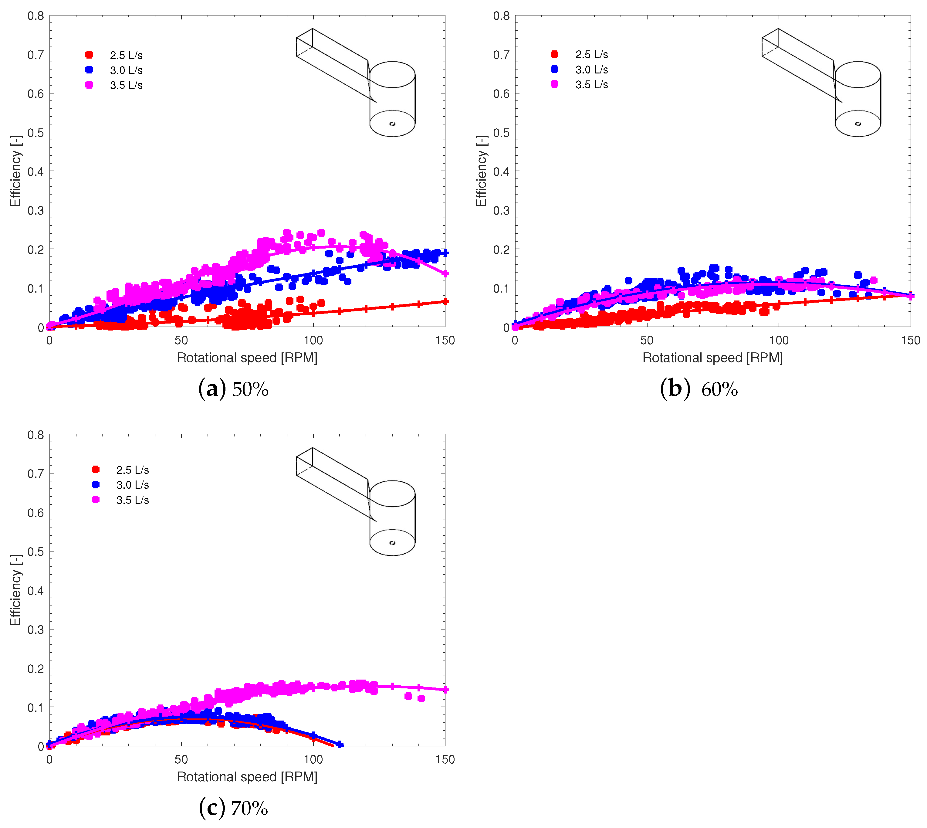
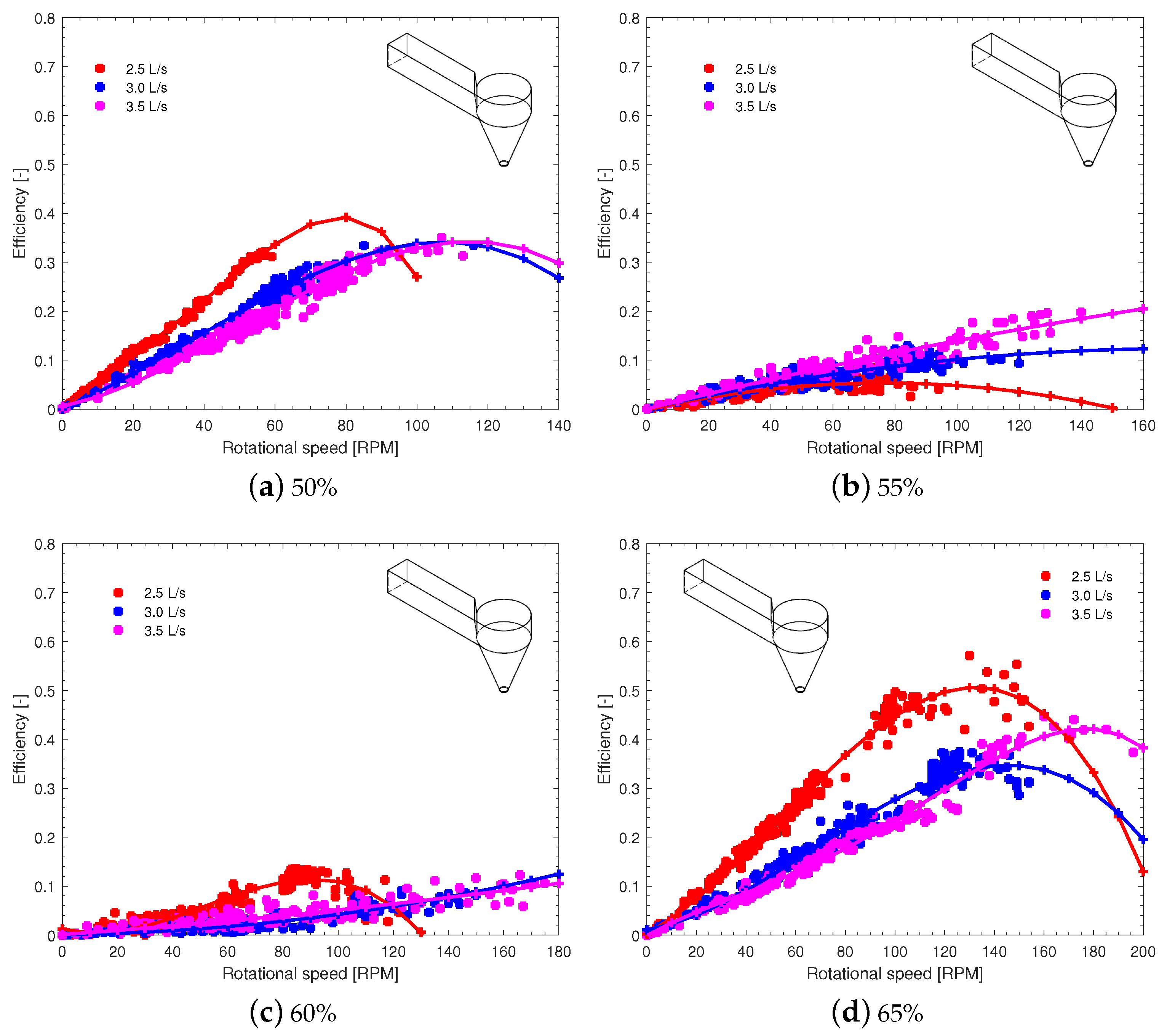
3.2. Model 2
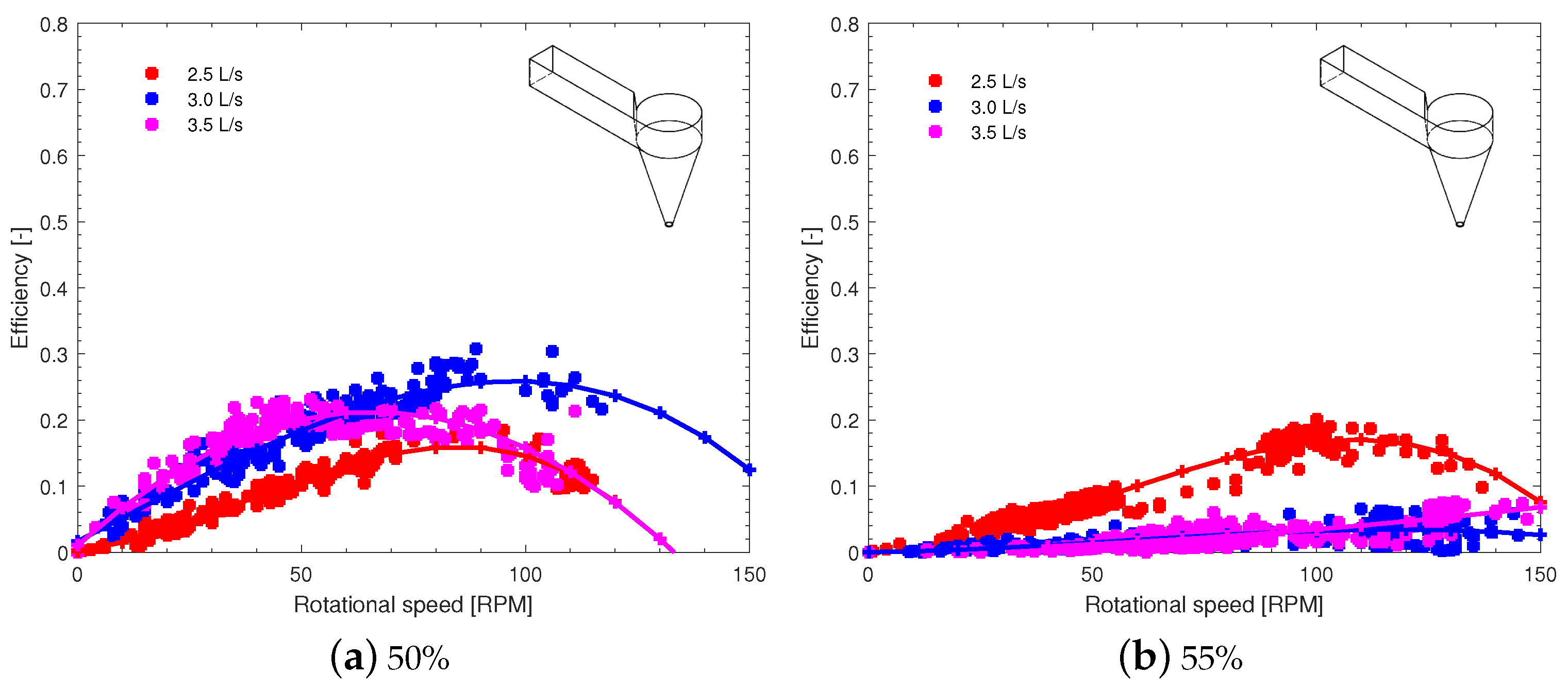
3.3. Model 3
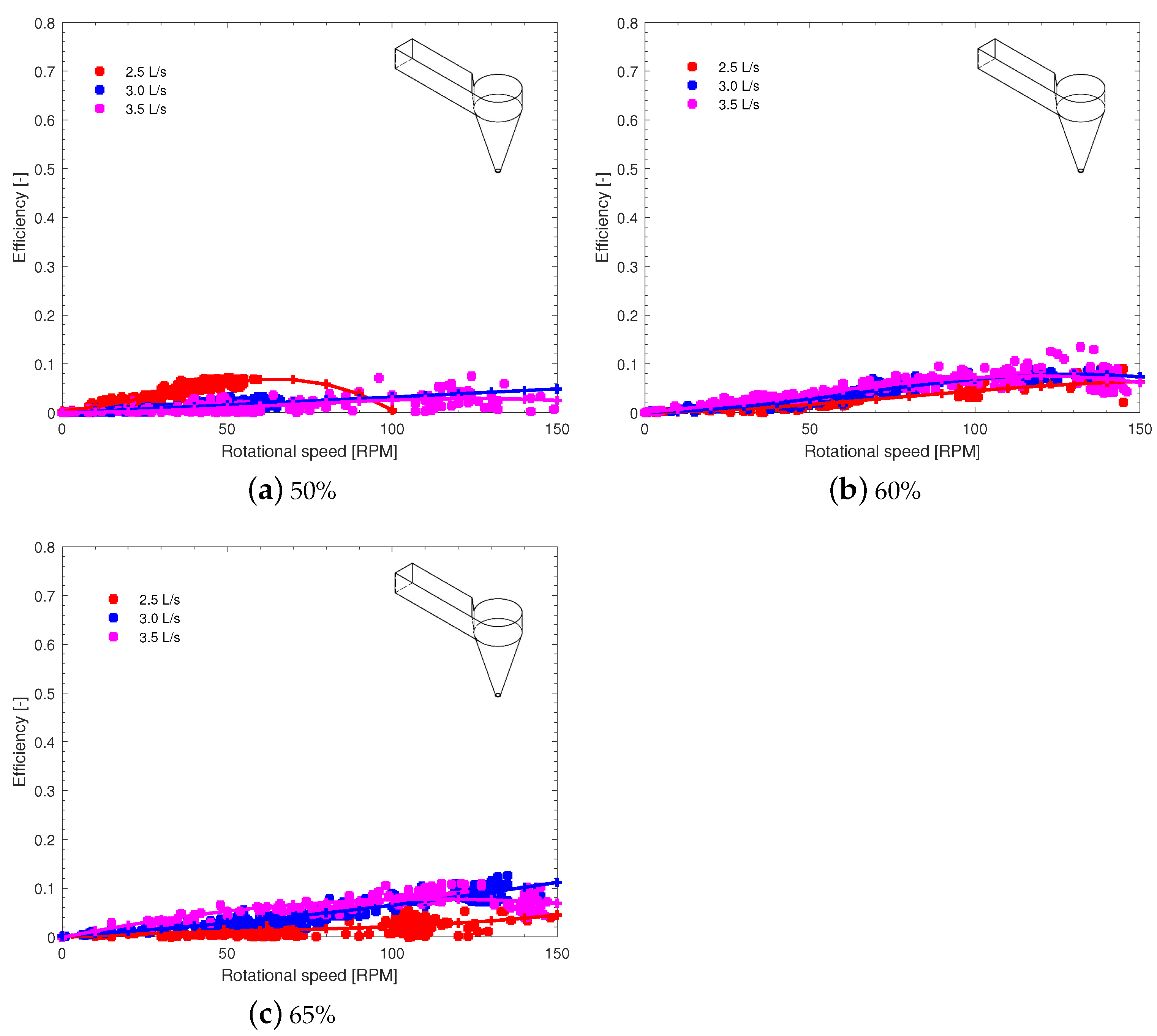
3.4. Model 4
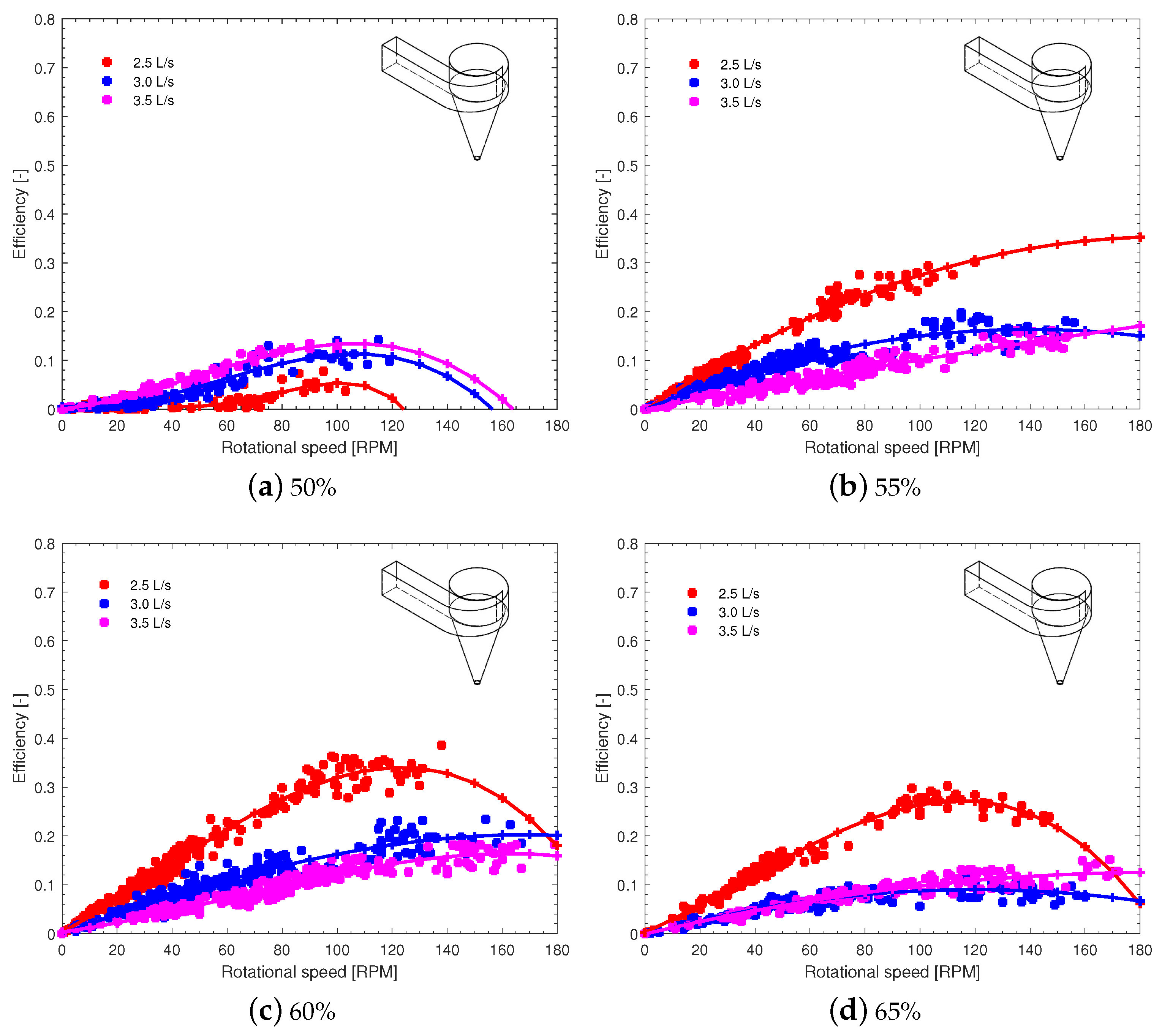
3.5. Model 5
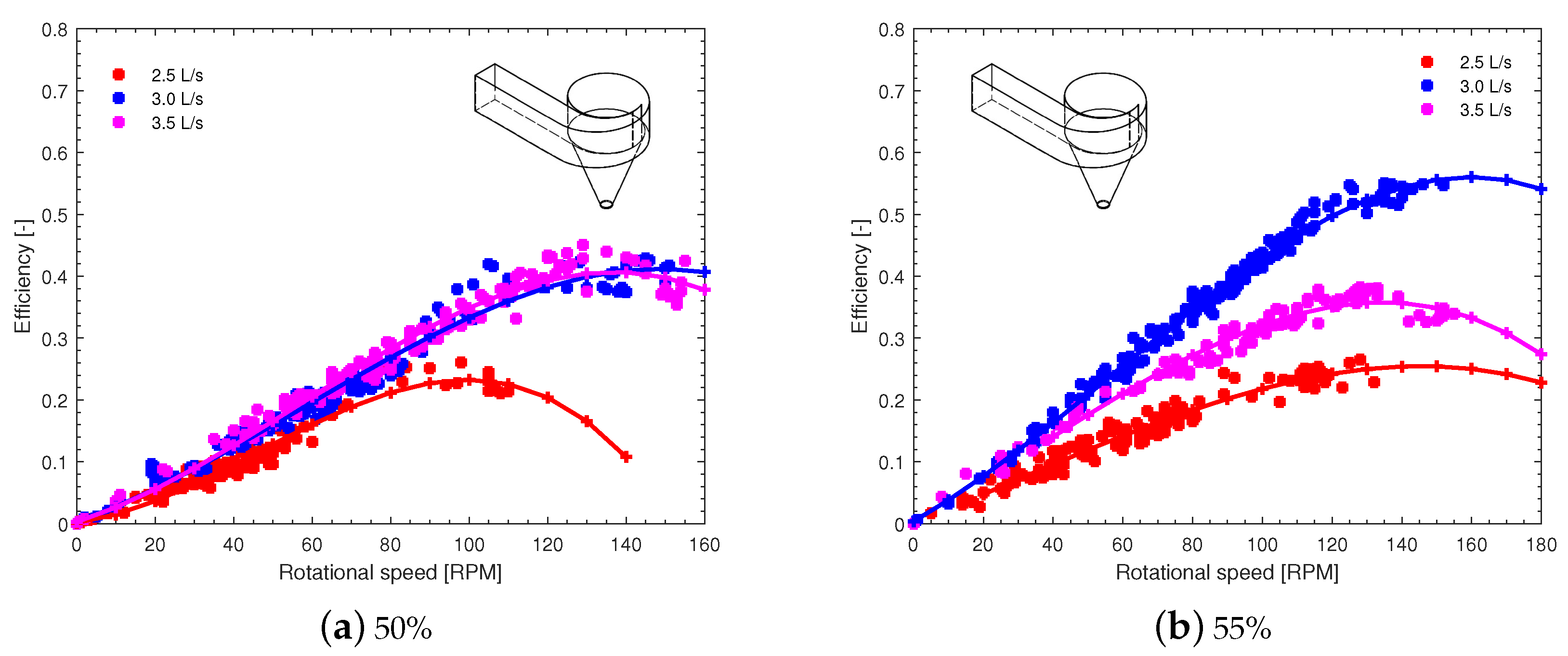
3.6. Model 6
3.7. Comparisons with Previous Studies
4. Experimental Images
5. Conclusions
Author Contributions
Funding
Data Availability Statement
Conflicts of Interest
References
- Wang, Q.; Dong, Z.; Li, R.; Wang, L. Renewable energy and economic growth: New insight from country risks. Energy 2022, 238, 122018. [Google Scholar] [CrossRef]
- Saidi, K.; Omri, A. The impact of renewable energy on carbon emissions and economic growth in 15 major renewable energy-consuming countries. Environ. Res. 2020, 186, 109567. [Google Scholar] [CrossRef] [PubMed]
- Mohsin, M.; Taghizadeh-Hesary, F.; Iqbal, N.; Saydaliev, H.B. The role of technological progress and renewable energy deployment in green economic growth. Renew. Energy 2022, 190, 777–787. [Google Scholar] [CrossRef]
- Ivanovski, K.; Hailemariam, A.; Smyth, R. The effect of renewable and non-renewable energy consumption on economic growth: Non-parametric evidence. J. Clean. Prod. 2021, 286, 124956. [Google Scholar] [CrossRef]
- Kishore, T.S.; Patro, E.R.; Harish, V.; Haghighi, A.T. A comprehensive study on the recent progress and trends in development of small hydropower projects. Energies 2021, 14, 2882. [Google Scholar] [CrossRef]
- Ugwu, C.O.; Ozor, P.A.; Mbohwa, C. Small hydropower as a source of clean and local energy in Nigeria: Prospects and challenges. Fuel Commun. 2022, 10, 100046. [Google Scholar] [CrossRef]
- Kuriqi, A.; Pinheiro, A.N.; Sordo-Ward, A.; Bejarano, M.D.; Garrote, L. Ecological impacts of run-of-river hydropower plants-Current status and future prospects on the brink of energy transition. Renew. Sustain. Energy Rev. 2021, 142, 110833. [Google Scholar] [CrossRef]
- Zhang, L.; Pang, M.; Bahaj, A.S.; Yang, Y.; Wang, C. Small hydropower development in China: Growing challenges and transition strategy. Renew. Sustain. Energy Rev. 2021, 137, 110653. [Google Scholar] [CrossRef]
- Yildiz, V.; Vrugt, J.A. A toolbox for the optimal design of run-of-river hydropower plants. Environ. Model. Softw. 2019, 111, 134–152. [Google Scholar] [CrossRef]
- Zheng, G.; Gu, Z.; Xu, W.; Lu, B.; Li, Q.; Tan, Y.; Wang, C.; Li, L. Gravitational surface vortex formation and suppression control: A review from hydrodynamic characteristics. Processes 2022, 11, 42. [Google Scholar] [CrossRef]
- Maika, N.; Lin, W.; Khatamifar, M. A review of gravitational water vortex hydro turbine systems for hydropower generation. Energies 2023, 16, 5394. [Google Scholar] [CrossRef]
- Velásquez, L.; Posada, A.; Chica, E. Surrogate modeling method for multi-objective optimization of the inlet channel and the basin of a gravitational water vortex hydraulic turbine. Appl. Energy 2023, 330, 120357. [Google Scholar] [CrossRef]
- Velásquez, L.; Romero-Menco, F.; Rubio-Clemente, A.; Posada, A.; Chica, E. Numerical optimization and experimental validation of the runner of a gravitational water vortex hydraulic turbine with a spiral inlet channel and a conical basin. Renew. Energy 2024, 220, 119676. [Google Scholar] [CrossRef]
- Betancour, J.; Romero-Menco, F.; Velásquez, L.; Rubio-Clemente, A.; Chica, E. Design and optimization of a runner for a gravitational vortex turbine using the response surface methodology and experimental tests. Renew. Energy 2023, 210, 306–320. [Google Scholar] [CrossRef]
- Marius, M.; Sajin, T.; Azzouz, A. Study of micro hydropower plant operating in gravitational vortex flow mode. Appl. Mech. Mater. 2013, 371, 601–605. [Google Scholar]
- Sritram, P.; Treedet, W.; Suntivarakorn, R. Effect of turbine materials on power generation efficiency from free water vortex hydro power plant. IOP Conf. Ser. Mater. Sci. Eng. 2015, 103, 012018. [Google Scholar] [CrossRef]
- Power, C.; McNabola, A.; Coughlan, P. A parametric experimental investigation of the operating conditions of gravitational vortex hydropower (GVHP). J. Clean Energy Technol. 2016, 4, 112–119. [Google Scholar] [CrossRef]
- Nishi, Y.; Inagaki, T. Performance and flow field of a gravitation vortex type water turbine. Int. J. Rotating Mach. 2017, 2017, 2610508. [Google Scholar] [CrossRef]
- Bajracharya, T.; Ghimire, R.; Timilsina, A. Design and performance analysis of water vortex powerplant in context of Nepal. In Proceedings of the 20th International Seminar on Hydropower Plants, Vienna, Austria, 14–16 November 2018; pp. 14–16. [Google Scholar]
- Franz, Z.Z. Gravitational Vortex Power Plant. 2022. Available online: http://www.zotloeterer.com/welcome/gravitation-water-vortex-power-plants (accessed on 13 December 2022).
- Sritram, P.; Suntivarakorn, R. The effects of blade number and turbine baffle plates on the efficiency of free-vortex water turbines. IOP Conf. Ser. Earth Environ. Sci. 2019, 257, 012040. [Google Scholar] [CrossRef]
- Sritram, P.; Suntivarakorn, R. The efficiency comparison of hydro turbines for micro power plant from free vortex. Energies 2021, 14, 7961. [Google Scholar] [CrossRef]
- Wichian, P.; Suntivarakorn, R. The effects of turbine baffle plates on the efficiency of water free vortex turbines. Energy Procedia 2016, 100, 198–202. [Google Scholar] [CrossRef]
- Velásquez, L.; Posada, A.; Chica, E. Optimization of the basin and inlet channel of a gravitational water vortex hydraulic turbine using the response surface methodology. Renew. Energy 2022, 187, 508–521. [Google Scholar] [CrossRef]
- Dhakal, S.; Timilsina, A.B.; Dhakal, R.; Fuyal, D.; Bajracharya, T.R.; Pandit, H.P.; Amatya, N. Mathematical modeling, design optimization and experimental verification of conical basin: Gravitational water vortex power plant. In Proceedings of the Dalam World Largest Hydro Conference, Portland, OR, USA, 14–17 July 2015. [Google Scholar]
- Dhakal, S.; Timilsina, A.B.; Dhakal, R.; Fuyal, D.; Bajracharya, T.R.; Pandit, H.P.; Amatya, N.; Nakarmi, A.M. Comparison of cylindrical and conical basins with optimum position of runner: Gravitational water vortex power plant. Renew. Sustain. Energy Rev. 2015, 48, 662–669. [Google Scholar] [CrossRef]
- Srihari, P.; Narayana, P.; Kumar, K.; Raju, G.J.; Naveen, K.; Anand, P. Experimental study on vortex intensification of gravitational water vortex turbine with novel conical basin. AIP Conf. Proc. 2019, 2200, 020082. [Google Scholar]
- Saleem, A.S.; Cheema, T.A.; Ullah, R.; Ahmad, S.M.; Chattha, J.A.; Akbar, B.; Park, C.W. Parametric study of single-stage gravitational water vortex turbine with cylindrical basin. Energy 2020, 200, 117464. [Google Scholar] [CrossRef]
- Bajracharya, T.R.; Shakya, S.R.; Timilsina, A.B.; Dhakal, J.; Neupane, S.; Gautam, A.; Sapkota, A. Effects of geometrical parameters in gravitational water vortex turbines with conical basin. J. Renew. Energy 2020, 2020, 5373784. [Google Scholar] [CrossRef]
- Sharif, A.; Siddiqi, M.U.R.; Tahir, M.; Ullah, U.; Aslam, A.; Tipu, A.K.; Arif, M.; Sheikh, N.A. Investigating the effect of inlet head and water pressure on the performance of single stage gravitational water vortex turbine. J. Mech. Eng. Res. Dev. 2021, 44, 156–168. [Google Scholar]
- Sharif, A.; Tipu, J.A.K.; Arif, M.; Abbasi, M.S.; Jabbar, A.U.; Noon, A.A.; Siddiqi, M.U.R. Performance Evaluation of a Multi-Stage Gravitational Water Vortex Turbine with optimum number of Blades. J. Mech. Eng. Res. Dev. 2022, 45, 35–43. [Google Scholar]
- Haryadi, H.; Subarjah, A.M.; Sugianto, S. Experimental study on 3D vortex gravitational turbine runner. AIP Conf. Proc. 2020, 2296, 020025. [Google Scholar]
- Ullah, R.; Cheema, T.A. Experimental investigation of runner design parameters on the performance of vortex turbine. Eng. Proc. 2022, 23, 14. [Google Scholar] [CrossRef]
- Muhammad, R.; Sharif, A.; Siddiqi, M. Performance investigation of a single-stage gravitational water vortex turbine accounting for water vortex configuration and rotational speed. J. Eng. Appl. Sci. 2022, 41, 44–55. [Google Scholar] [CrossRef]
- Edirisinghe, D.S.; Yang, H.S.; Gunawardane, S.; Alkhabbaz, A.; Tongphong, W.; Yoon, M.; Lee, Y.H. Numerical and experimental investigation on water vortex power plant to recover the energy from industrial wastewater. Renew. Energy 2023, 204, 617–634. [Google Scholar] [CrossRef]
- Sinaga, D.A.; Septiyanto, M.D.; Arifin, Z.; Rusdiyanto, G.; Prasetyo, S.D.; Hadi, S. The Effect of Blade Distances on the Performance of Double-Stage Gravitational Water Vortex Turbine. J. Adv. Res. Fluid Mech. Therm. Sci. 2023, 109, 196–209. [Google Scholar] [CrossRef]
- Obozov, A.; Akparaliev, R.; Mederov, T.; Ashimbekova, B.; Tolomushev, A.; Orazbaev, K. Research and development of a gravitational water vortex micro-HPP in the conditions of Kyrgyzstan. Energy Rep. 2023, 10, 544–557. [Google Scholar] [CrossRef]
- Zamora-Juárez, M.Á.; Guerra-Cobián, V.H.; Ferri no-Fierro, A.L.; Bruster-Flores, J.L.; Fonseca Ortiz, C.R.; López-Rebollar, B.M. Assessment of a prototype of gravitational water vortex turbine: Experimental validation of efficiency. Clean Technol. Environ. Policy 2024, 26, 691–711. [Google Scholar] [CrossRef]
- Haryadi; Sugianto; Prasetyo; Setiawa, D. Experimental and Numerical Study on Conical Gravitational Water Vortex Turbine with 3D Runner. J. Adv. Res. Fluid Mech. Therm. Sci. 2024, 114, 1–14. [Google Scholar] [CrossRef]
- Alfeuz, A.; Tamiri, F.; Yan, F.Y.; Muzammil, W.K.; Hong, M.G.J.; Mahmod, D.S.A.; Bohari, N.; Ismail, M.A. Performance Analysis of a Crossflow Vortex Turbine for a Gravitational Water Vortex Power Plant. J. Adv. Res. Fluid Mech. Therm. Sci. 2024, 116, 13–26. [Google Scholar] [CrossRef]
- Vinayakumar, B.; Antony, R.; Binson, V.; Youhan, S. Experimental and numerical study on gravitational water vortex power plant for small water bodies. e-Prime-Adv. Electr. Eng. Electron. Energy 2024, 7, 100460. [Google Scholar] [CrossRef]


| Reference | Inlet Channel Type | Basin Type | Experimental Installation Characteristics | Relevant Aspects |
|---|---|---|---|---|
| [25] | Tangential | Conical | Square inlet channel with a 400 mm side and an 1850 mm channel length inclined at 3°. Basin diameter of 800 mm, height of 750 mm, and outlet diameter of 120 mm | Efficiency of 74.35%, runner located at 50% from the top of the basin, with a flow rate of 0.018 m3/s |
| [26] | Tangential | Cylindrical and conical | The cylindrical and conical basins both had a diameter of 600 mm and a height of 850 mm, with a six-blade runner of 420 mm in diameter. | Maximum efficiency for the conical basin was 36.84% at a runner position of 60.5%, while for the cylindrical basin it was 27.75% at 50%. Output power peaked in both basins when the runner was positioned between 65% and 75% of the basin height from the top. |
| [27] | Tangential inclined | Conical | The conical basin has a diameter of 600 mm and a height of 850 mm. The hole diameter is mm. At the top of the basin, six injectors of 50 mm diameter and 60° orientation were considered. | The maximum efficiency achieved was 42.47% for a mass flow rate of 15.92 kg/s. |
| [28] | Tangential | Cylindrical | Three types of blades were examined with curvature radii of 5.08 cm, 10.16 cm, and infinite (flat blades). | Maximum efficiency obtained was 20%. |
| [29] | Tangential | Conical | The study was conducted with a gross head of 0.27 m and a flow rate of 0.0065 m3/s. The test setup consisted of a conical chamber with a 400 mm top diameter and a 60 mm outlet. Water entered the basin tangentially through a channel with a 13° notch. The runner, with an outer diameter of 40 mm, was placed at 65% of the basin height. | The maximum efficiency achieved was 47.8%. |
| [30] | Tangential | Conical | The water enters the conical basin through the inlet channel, which consists of an open rectangular cross-section channel. The basin has a height of 610 mm, a top diameter of 400 mm, and a discharge hole diameter of 56 mm. | Maximum efficiency of 54.44% was observed at a height of 0.70 m and flow rates of 0.004 m3/s. |
| [22] | Tangential | Cylindrical | The test bench with a cylindrical basin has a diameter of 1 m and a height of 0.5 m, with an outlet drain of 0.2 m at the bottom. | At a water flow rate of 0.02 m3/s, the maximum efficiency was 9.09%. |
| [31] | Tangential | Conical | Water enters the conical basin through an open rectangular inlet channel, which includes a baffle to guide the flow tangentially. The channel is connected to a small round basin, 300 mm high and 600 mm in diameter. | Maximum torque (0.84 N-m) and rotational speed (114 rpm) were achieved with a 5-blade runner, reaching an efficiency of 43% at a height of 0.98 m. |
| [32] | Tangential | Cylindrical | The runner used in the tests, 3D printed, has a diameter of 200 mm, a height of 300 mm, and a blade twist angle of 60%. The number of blades was set to 5. The cylindrical basin where the runner was installed has a diameter of 0.8 m and an outlet hole of 0.14 m. | The maximum efficiency achieved was 25% for a rotational speed between 90 and 120 rpm. |
| [33] | spiral | Conical | The runner used in the tests had 4 Savonius-profile blades. A constant inlet flow rate of 4 L/s was maintained for all experiments. | The results indicate that the runner should be installed at 60% of the basin height. Blades inclined in the vertical plane are recommended for energy extraction near the bottom of the cone, while cross-flow blades are more suitable for the rotational flow near the top, in the surface vortex region. |
| [34] | Tangential | Conical | The basin has an upper diameter of 400 mm, a height of 610 mm, and a 57 mm outlet for stable vortex formation, with a cone angle of 23°. Water enters through a rectangular inlet channel. The runner, positioned between 65% and 75% of the basin height, has a diameter of 200 mm, a height of 70 mm, a hub diameter of 30 mm, and a shaft diameter of 12.5 mm. | The results indicate that a fully developed air core is achieved at a rotational speed of 172 rpm and a vortex height of 0.59 m, representing the ideal operating conditions for maximum efficiency and power output. |
| [35] | spiral | Conical | A conical vortex basin was designed with a maximum diameter of 625 mm, extended to 875 mm by a spiral design that guided the water flow. The water channel, 325 mm wide, converged towards the spiral inlet with a 9° inclined guide channel. The conical basin’s drainage outlet had a diameter of 150 mm. | Maximum efficiency obtained was 60.5% for a flow rate of 60 m3/h and a head of 0.5 m. |
| [36] | Tangential | Conical | They tested double-stage vortex turbines (2 turbines installed on the same shaft) using different flow rates and variations in the distance between runners. | The findings indicated that increasing the spacing between the blades led to improved performance at a higher flow rate. Specifically, with a flow rate of 9.5 L/s and a blade separation of 150 mm, the system achieved a total mechanical power of 28.51 W and an efficiency of 28.92%. |
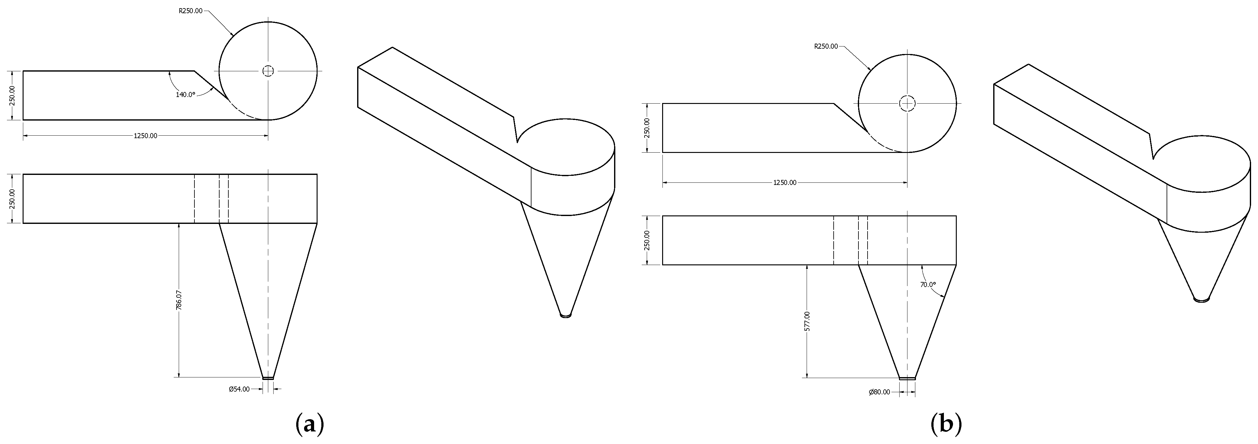
| [14] | Tangential | Conical | Basin diameter of 500 mm, outlet hole of 80 mm, cone height 577 mm, cone angle 20°, a channel with a square cross-section of side 250 mm, and length 1250 mm. runner with 6 curved blades with a helical angle of 55°, upper and lower diameters of 250 mm and 115 mm, respectively. | Efficiency of 49.5%. |
| [37] | Tangential | Cylindrical | Runner with 5 blades, external diameter of 300 mm, internal diameter of 20 mm, blade height of 120 mm. | Maximum efficiency was 56.8% with a flow rate of 0.018 m3/s. |
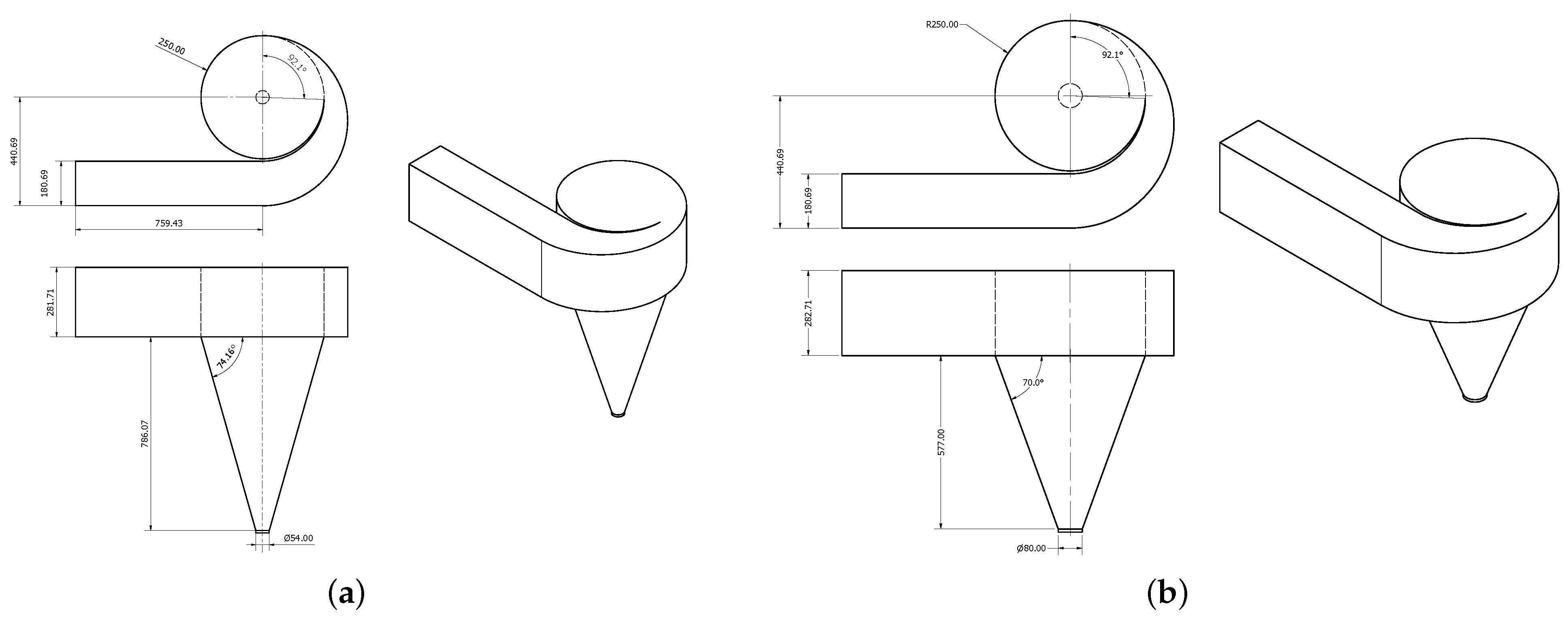
| [13] | spiral | Conical | Rectangular inlet of height 282.5 mm, width 180.5 mm, and length 759 mm, basin diameter of 500 mm, cone height 786 mm. spiral inlet angle of 92.14°. | Maximum efficiency was 60.77% for a runner position of 55%. |
| [38] | Tangential | Cylindrical | Rectangular inlet channel of base 150 mm and height of 300 mm. Cylindrical basin with a diameter and height of 500 mm. Basin outlet diameter of 100 mm. | Maximum experimentally obtained efficiency was 58.13% for a flow rate of 6.0 L/s. |
| [39] | Tangential | Conical | The runner with 5 blades has a height of 240 mm, a blade angle of 60°, a helix angle of 63°, and a conicity angle of 20°. Its upper diameter is 350 mm, while the middle diameter is 262.7 mm. | Maximum efficiency was 28% for a flow rate of 0.00477 m3/s. |
| [40] | Tangential | Cylindrical | The setup consists of a channel with a rectangular cross-sectional area, a cylinder with a height of 550 mm, and a diameter of 390 mm. The runner’s upper diameter is 0.13 m, the outlet diameter is 0.20 m, with a height of 0.20 m, and 18 blades. | The maximum reported efficiency, for a runner that showed a torque and output power of 0.27 m and 1.49 m, respectively, was 18.98%. |
| [41] | spiral | Cylindrical | The rectangular inlet channel measures 15 cm wide, 30 cm high, and 145 cm long. The vortex chamber has a spiral shape with an internal diameter of 47 cm, while the external spiral arm connecting to the water channel has a diameter of 58 cm. The experimental setup includes two tanks of 500 and 300 L, respectively. Two runners with four curved blades (straight and inclined) with an external diameter of 250 mm and a height of 150 mm were employed. | Maximum efficiency of 56% for a flow rate of 2.0 m3/min. |
| Symbol | Variable | Runner 1 | Runner 2 |
|---|---|---|---|
| Blade inlet angle [°] | 16.00 | 16.00 | |
| Blade outlet angle [°] | 90.00 | 90.00 | |
| Water inlet angle [°] | 40.00 | 40.00 | |
| Water outlet angle [°] | 42.70 | 42.70 | |
| Blade twist angle [°] | 68.80 | 55 | |
| L | runner height [mm] | 200 | 200 |
| Upper diameter [mm] | 291 | 252 | |
| Lower diameter [mm] | 163 | 122 | |
| Z | Number of blades | 6 | 6 |
| Efficiency [%] | ||||||
|---|---|---|---|---|---|---|
| Runner 1 | Runner 2 | |||||
| Flow Rate [L/s] | 50% | 60% | 70% | 50% | 60% | 70% |
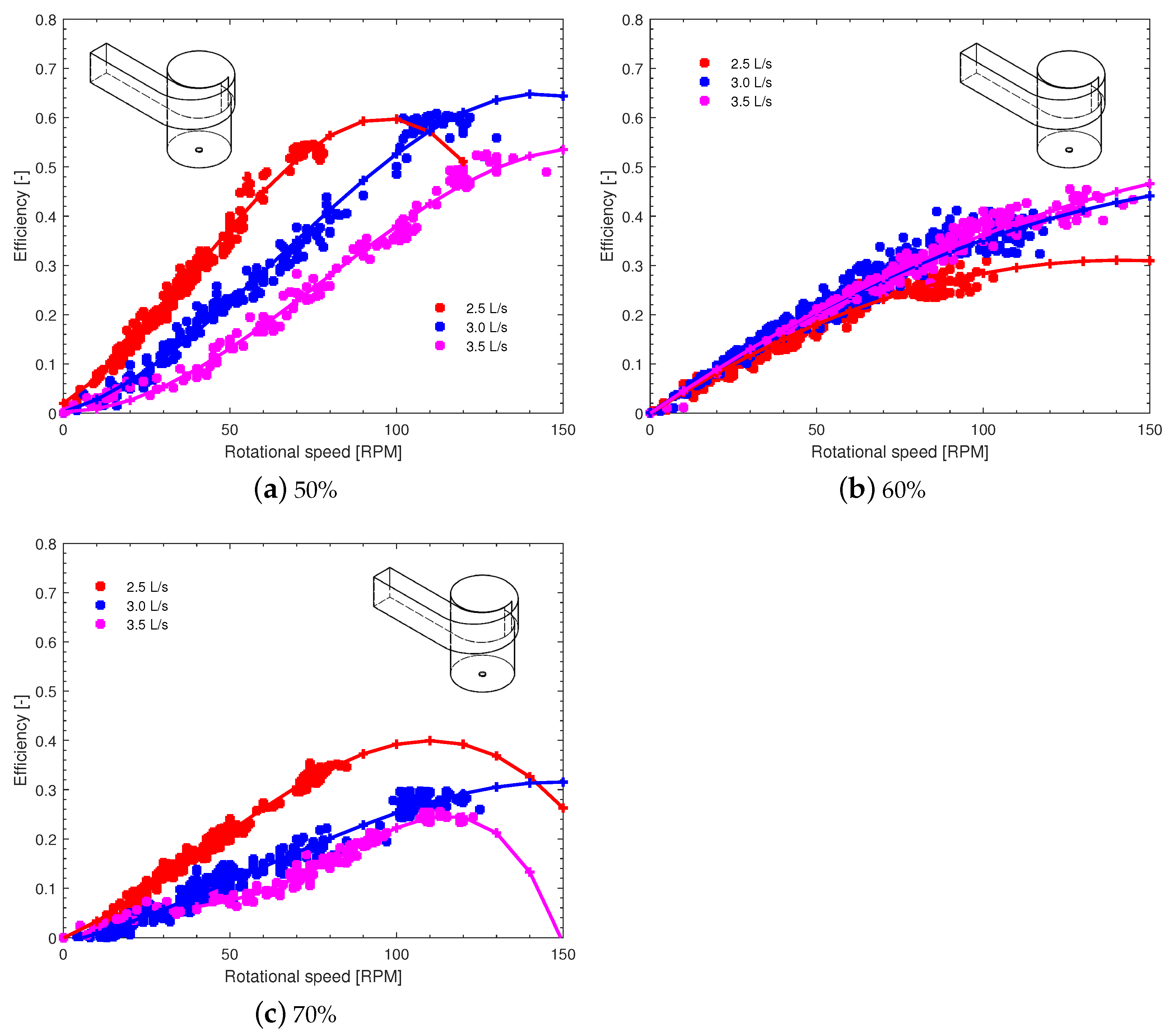
| 2.5 | 54.44 | 30.62 | 35.53 | 37.54 | 15.9 | 25.22 |
| 3.0 | 60.85 | 40.94 | 29.69 | 52.67 | 16.26 | 42.12 |
| 3.5 | 52.25 | 45.49 | 25.25 | 21.11 | 10.00 | 42.46 |
| Efficiency [%] | ||||||
|---|---|---|---|---|---|---|
| Runner 1 | Runner 2 | |||||
| Flow Rate [L/s] | 50% | 60% | 70% | 50% | 60% | 70% |
| 2.5 | 16.03 | 13.50 | 5.55 | 7.07 | 5.53 | 8.28 |
| 3.0 | 25.83 | 16.08 | 10.51 | 18.78 | 15.06 | 8.96 |
| 3.5 | 20.24 | 15.63 | 14.05 | 24.19 | 12.05 | 15.85 |
| Efficiency | |||||
|---|---|---|---|---|---|
| Runner 1 | Runner 2 | ||||
| Flow Rate [L/s] | 50% | 55% | 50% | 60% | 65% |
| 2.5 | 18.47 | 20.12 | 7.00 | 8.96 | 5.30 |
| 3.0 | 30.80 | 6.57 | 3.22 | 8.43 | 12.62 |
| 3.5 | 23.09 | 7.18 | 7.10 | 13.44 | 10.98 |
| Efficiency | ||||||
|---|---|---|---|---|---|---|
| Runner 1 | Runner 2 | |||||
| Flow Rate [L/s] | 50% | 55% | 50% | 55% | 60% | 65% |
| 2.5 | 18.09 | 35.96 | 32.03 | 6.28 | 13.58 | 57.16 |
| 3.0 | 18.02 | 26.36 | 33.37 | 12.93 | 8.30 | 37.42 |
| 3.5 | 36.65 | 20.57 | 35.01 | 18.4 | 12.27 | 44.03 |
| Efficiency | ||||||
|---|---|---|---|---|---|---|
| Runner 1 | Runner 2 | |||||
| Flow Rate [L/s] | 50% | 55% | 50% | 55% | 60% | 65% |
| 2.5 | 29.46 | 35.81 | 7.75 | 30.59 | 38.55 | 30.22 |
| 3.0 | 36.47 | 60.79 | 14.14 | 19.76 | 23.15 | 12.56 |
| 3.5 | 40.35 | 41.47 | 12.73 | 15.34 | 18.18 | 14.88 |
| Efficiency | ||||||
|---|---|---|---|---|---|---|
| Runner 1 | Runner 2 | |||||
| Flow Rate [L/s] | 50% | 55% | 50% | 55% | 60% | 65% |
| 2.5 | 26.04 | 26.51 | 9.24 | 16.33 | 23.57 | 21.18 |
| 3.0 | 41.92 | 38.19 | 24.89 | 38.87 | 40.67 | 41.85 |
| 3.5 | 45.05 | 54.68 | 24.60 | 45.55 | 36.23 | 38.69 |
| Runner | Inlet Channel | Basin | Flow Rate | |||||||
|---|---|---|---|---|---|---|---|---|---|---|
| Model | 1 | 2 | Spiral | Tangential | Conical | Cylindrical | [L/s] | Position | η (%) | |
| 1 | 1 | x | x | x | 3.0 | 50 | 60.85 | |||
| 2 | 1 | x | x | x | 3.0 | 50 | 52.67 | |||
| 3 | 2 | x | x | x | 3.0 | 50 | 25.83 | |||
| 4 | 2 | x | x | x | 3.5 | 50 | 24.19 | |||
| 5 | 3 | x | x | x | 3.0 | 50 | 30.80 | |||
| 6 | 3 | x | x | x | 3.5 | 60 | 13.44 | |||
| 7 | 4 | x | x | x | 3.5 | 50 | 36.65 | |||
| 8 | 4 | x | x | x | 2.5 | 65 | 57.16 | |||
| 9 | 5 | x | x | x | 3.0 | 55 | 60.79 | |||
| 10 | 5 | x | x | x | 2.5 | 60 | 38.55 | |||
| 11 | 6 | x | x | x | 3.5 | 55 | 54.68 | |||
| 12 | 6 | x | x | x | 3.5 | 55 | 45.55 | |||
| 13 | - | x | x | x | 3.0 | 55 | 60.70 | |||
| 14 | - | x | x | x | 3.125 | 65 | 52.20 | |||
Disclaimer/Publisher’s Note: The statements, opinions and data contained in all publications are solely those of the individual author(s) and contributor(s) and not of MDPI and/or the editor(s). MDPI and/or the editor(s) disclaim responsibility for any injury to people or property resulting from any ideas, methods, instructions or products referred to in the content. |
© 2024 by the authors. Licensee MDPI, Basel, Switzerland. This article is an open access article distributed under the terms and conditions of the Creative Commons Attribution (CC BY) license (https://creativecommons.org/licenses/by/4.0/).
Share and Cite
Velásquez, L.; Rengifo, J.P.; Urrego, J.; Rubio-Clemente, A.; Chica, E. Experimental Assessment of Hydrodynamic Behavior in a Gravitational Vortex Turbine with Different Inlet Channel and Discharge Basin Configurations. Energies 2024, 17, 5773. https://doi.org/10.3390/en17225773
Velásquez L, Rengifo JP, Urrego J, Rubio-Clemente A, Chica E. Experimental Assessment of Hydrodynamic Behavior in a Gravitational Vortex Turbine with Different Inlet Channel and Discharge Basin Configurations. Energies. 2024; 17(22):5773. https://doi.org/10.3390/en17225773
Chicago/Turabian StyleVelásquez, Laura, Juan Pablo Rengifo, José Urrego, Ainhoa Rubio-Clemente, and Edwin Chica. 2024. "Experimental Assessment of Hydrodynamic Behavior in a Gravitational Vortex Turbine with Different Inlet Channel and Discharge Basin Configurations" Energies 17, no. 22: 5773. https://doi.org/10.3390/en17225773
APA StyleVelásquez, L., Rengifo, J. P., Urrego, J., Rubio-Clemente, A., & Chica, E. (2024). Experimental Assessment of Hydrodynamic Behavior in a Gravitational Vortex Turbine with Different Inlet Channel and Discharge Basin Configurations. Energies, 17(22), 5773. https://doi.org/10.3390/en17225773