1. Introduction
In recent years, advanced small mobile nuclear reactors gained attention due to their flexibility when deployed in remote areas. These reactors provide a reliable source of energy that can be quickly installed, making them valuable for regions where conventional power grids are not feasible [
1]. Their potential to enhance future energy systems aligns with global efforts toward green, low-carbon, and sustainable development. Among these technologies, the helium-xenon (HeXe)-cooled solid-state nuclear reactor stands out as a promising candidate for a mobile nuclear power source [
2]. The HeXe mixture, used as a coolant in the reactor core, offers excellent thermal properties and compressibility, which are critical for maintaining efficient heat transfer [
3]. Furthermore, this reactor operates based on an advanced closed Brayton cycle (CBC), known for its high thermal efficiency. As a result, the HeXe-cooled solid-state reactor represents a forward-looking technological route with significant potential for both energy security and environmental sustainability in the future.
Currently, numerous investigations can be found on sCO
2-cooled nuclear reactor systems coupled with CBC [
4,
5,
6], while those on HeXe-cooled power systems are still limited and thus need to be further focused on. Over the years, some conceptual designs for HeXe-cooled reactors were preliminarily proposed, particularly for space and mobile power systems. The Prometheus project of the United States was proposed in the 2000s [
7], which introduced a 1 MWt HeXe-cooled reactor designed for space propulsion and long-term energy supply. This design featured 288 UO
2 fuel rods arranged compactly with a combination of sliding reflector segments and a central emergency rod to minimize weight and volume. In 2009, Gallo [
8] proposed a Brayton rotating unit system for space reactor power, using a HeXe mixture in a CBC. Their design achieved up to 26% thermal efficiency, making it a promising candidate for high-efficiency space reactors. More recently, Meng [
9] conducted a neutronics analysis of a megawatt-class HeXe-cooled reactor, focusing on the use of annular UO
2 fuel rods and various control rod configurations to optimize reactivity and neutron management. Guan [
10] then proposed a micro-transportable gas-cooled reactor using a HeXe mixture, with core mass optimization achieved through BeO moderators and reflector sliders, offering a portable and long-term power solution. In addition, Ma [
11] explored the load loss characteristics of space nuclear power systems, emphasizing the role of multiple Brayton loops in maintaining system safety and performance during power fluctuations. These designs collectively mark significant advancements in HeXe reactor technologies for space and mobile applications.
Despite the significant progress in developing steady-state conceptual designs, there remains a pressing need to focus on optimizing design parameters for the system dynamic behavior. The complexity of the HeXe-cooled reactor system lies not only in its individual components, such as the reactor core, printed circuit heat exchanger (PCHE), and turbomachinery, but also in the intricate coupling and dynamic interactions between these elements. The behavior of each component influences the overall system’s response under varying operational conditions.
Numerous methods were used to analyze the dynamic performance of HeXe-cooled nuclear reactor-powered systems. On the experimental side, Wright [
12] conducted operational tests on a CBC test-loop at Sandia National Laboratories (SNL). The test loop was designed to simulate the operational behavior of reactor-driven CBC systems using HeXe gas mixtures, proving the feasibility of such a novel power system, and providing valuable data for validating their system models. Despite the insights gained from these experiments, challenges such as high costs, long testing periods, and limited data acquisition restrict their widespread use.
Consequently, researchers increasingly turned to simulation programs for analysis. Wang [
13] developed a dynamic simulation code for gas-cooled reactors using a CBC system. Their simulation examined transient behaviors and operational conditions, demonstrating the system’s inherent safety and reliability during reactivity insertion accidents. Meng [
14] further enhanced simulation efforts by developing a one-dimensional simulation code SIMCODE for space nuclear reactors, focusing on transient accident conditions and system safety evaluations. Additionally, Wang [
15] created a HeXe mixture physical property calculation program and validated it through comparisons with existing data, which proved highly accurate. Liao [
16] developed a Brayton cycle system analysis program for a HeXe-cooled nuclear reactor, focusing on dynamic simulation of system operating characteristics under various reactivity control methods and analyzing the effects of altitude and flight speed on power and heat dissipation. These simulation efforts provide a cost-effective and efficient means of studying HeXe reactor designs, offering deeper insights into system behavior without the limitations of experimental testing.
Although various dynamic simulation programs have been developed, most are tailored to space applications [
14,
17], leaving a gap in the tools available for land-based, mobile nuclear power systems. The unique operational demands of mobile systems, especially under dynamic conditions, require more specialized tools. Therefore, there is an urgent need to develop simplified, fast lumped-parameter simulation models. Such tools would allow for more efficient evaluation of the operational characteristics of HeXe-cooled nuclear power systems under dynamic conditions, providing valuable insights for the optimization of system parameters and guiding the development of more robust designs.
This paper presents the development of a dynamic analysis program for a land-based HeXe-cooled mobile nuclear power system. The program focuses on capturing the transient thermohydraulic characteristics of those key individual components, including the reactor, PCHE, and turbomachinery, through lumped-parameter mathematical modeling. A core feature of the program is the incorporation of a closed-cycle mass conservation algorithm, enabling accurate dynamic simulations of the system’s performance. The validity of the developed program was tested, demonstrating its capability to model real-world scenarios and achieve HeXe mass conservation of a closed-cycle system. Finally, a system startup condition is simulated, and the results show that the system successfully completes the startup process, achieving an overall thermal efficiency of 32.5%. This work provides a foundation for further optimization and analysis of mobile nuclear power systems operating under dynamic conditions, addressing a critical gap in current research and offering a valuable tool for future system designs.
2. Methodology
In this section, the layout and working principle of the nuclear-powered HeXe CBC is briefly introduced. Next, the detailed modeling of the key components as well as their mathematical expressions are given. Finally, the calculation flowchart of the system dynamic operation is explained, including the iteration of HeXe mass conservation in the closed cycle.
2.1. Introduction of the Power System
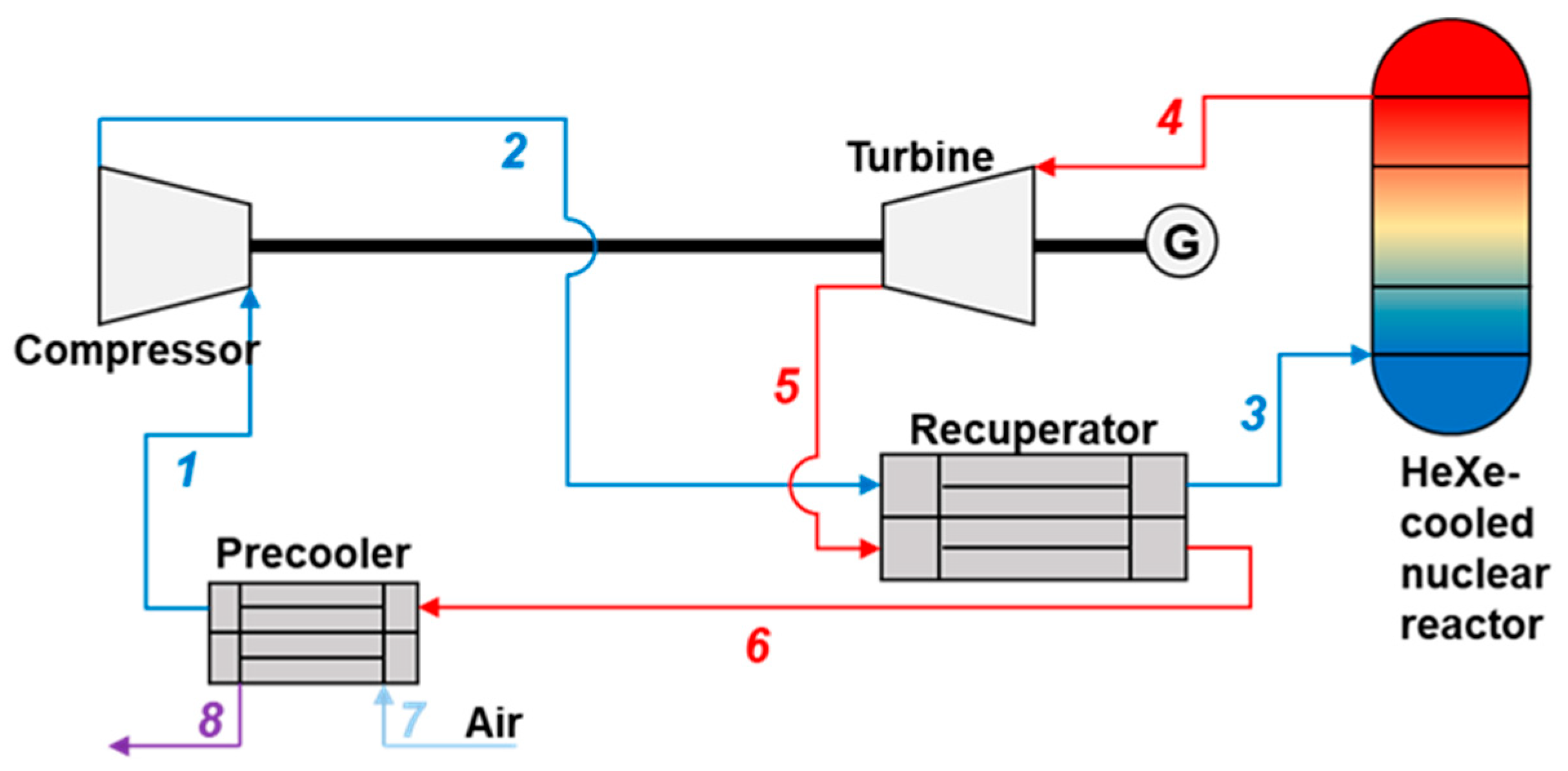
The gas-cooled nuclear reactor system operates based on a closed Brayton cycle, utilizing a HeXe gas mixture as the working fluid. As shown in
Figure 1, the system consists of several key components, including the reactor core, a compressor, a turbine, a recuperator, and a precooler. The gas coolant absorbs heat from nuclear fission in the reactor. The heated gas (point 4) is directed into the turbine (point 5), where its thermal energy is converted into mechanical energy to generate electricity. After passing through the turbine, the gas enters the recuperator (point 3). In fact, the recuperator plays a critical role in improving overall cycle efficiency by recovering residual heat from the working fluid before it is cooled further in the next step. The extracted heat is reused to preheat the incoming cooler gas that will enter the reactor, thus reducing the energy needed to reheat it in the reactor. Next, the cooled gas moves to the precooler (point 6), where external air (point 7 and 8) is used to reduce its temperature further. The gas is subsequently compressed in the compressor (point 2) to raise its pressure, preparing it for re-entry into the reactor core to repeat the cycle.
This closed-loop system is highly efficient, as it continually recycles the HeXe mixture, minimizing losses and optimizing the conversion of thermal energy into electrical energy. The use of helium and xenon as the working fluid is particularly advantageous due to their excellent thermodynamic properties, such as high thermal conductivity and low neutron absorption cross-section, making the system suitable for mobile nuclear power generation.
2.2. Turbomachine Modeling
The turbomachinery consists of a compressor, a turbine, and an alternator, and they play critical roles in the CBC power system. The performance of these components is characterized by their pressure and temperature ratios. As described in Equation (1), the pressure ratio (
) and temperature ratio (
) for both the compressor and turbine are functions of the HeXe mass flow rate (
) and the shaft rotational speed (
). For the compressor, subscripts 1 and 2 are at its inlet and outlet, respectively. Similarly, subscripts 4 and 5 are the turbine inlet and outlet, respectively.
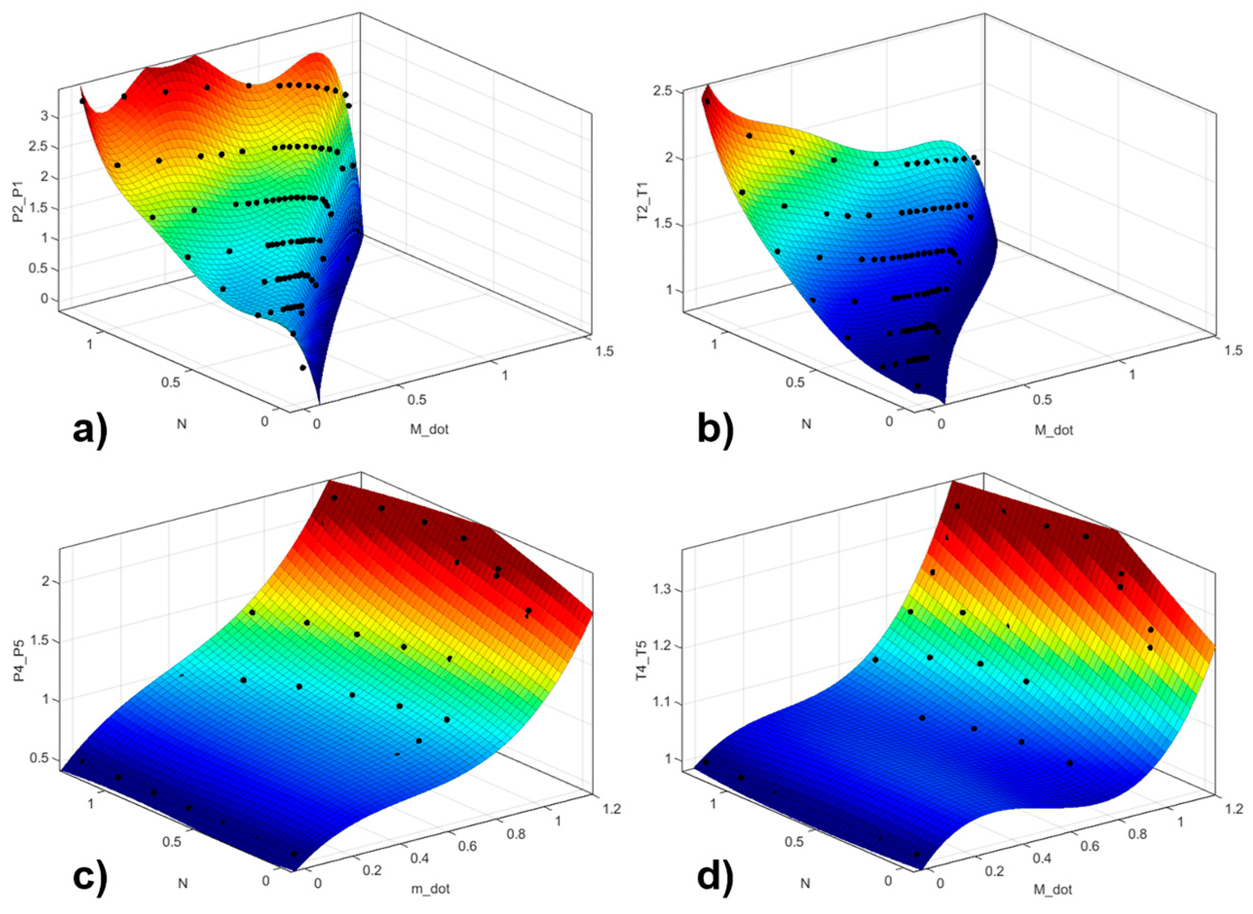
The performance curves illustrate the relationships between the mass flow rate, rotational speed, and the pressure and temperature ratios for both the compressor and turbine under off-design operating conditions. These curves are essential for understanding the dynamic response of the CBC power system. The performance curve shown in
Figure 2 originates from those of a 132 kWe turbomachine designed by the Prometheus project [
17], with a similar variation tendency, but the values are scaled based on our own design.
Equation (2) outlines the work accomplished by the compressor and turbine, which are the functions of the mass flow rate and the enthalpy difference across the components. The network output of the system is the difference between the turbine’s work and the compressor’s work.
2.3. Reactor Thermal Modeling
The point kinetic (PK) model is used to describe the time-varying features of the reactor. This simplified model states that the spatial shapes of the angular flux and the precursor concentrations remain in the fundamental mode during the transient period, while only the amplitudes change. It consists of seven ordinary differential equations (ODEs), resulting in a fast solution in dynamic neutronics analysis for the nuclear-powered system:
where
is the nuclear power and
is the reactivity.
,
,
, and
represent the point kinetic parameters, whose values are obtained by the pre-conducted Monte Carlo modeling of the reactor [
10]. The net reactivity is divided into external reactivity
and feedback reactivity
. Temperature feedback can significantly influence the safety of a nuclear system, and its specific form can be found in our previous study [
18].
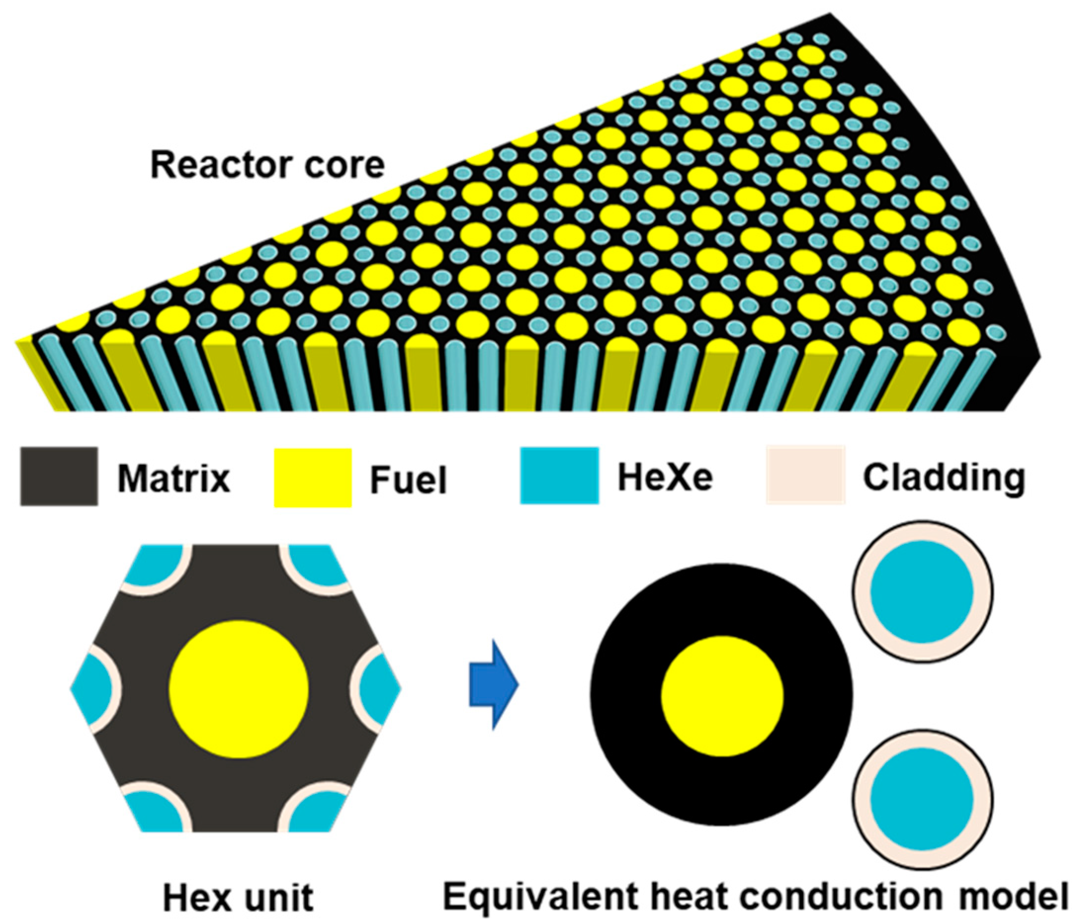
Figure 3 shows the structure of 1/12 of the solid-state gas-cooled reactor core, which is composed of multiple hexagonal units. Each contains key components such as the fuel, cladding, HeXe coolant, and the matrix material. The yellow regions represent the fuel, the black areas denote the matrix, the blue represents the HeXe mixture used for cooling, and the beige indicates the cladding material, which encapsulates the coolant channel.
To simplify the heat conduction calculations, the hexagonal unit is simplified into an equivalent cylindrical heat conduction model based on the principle of the equivalent area. In fact, the equivalent area method is commonly used to simplify and analyze heat transfer behaviors of the irregular geometry of the cylindrical solid-state reactor core [
19]. This transformation enables easier computation of heat transfer through the reactor core by modeling the system as concentric cylindrical layers. The fuel is represented by the innermost circle, surrounded by layers representing the cladding, HeXe coolant, and matrix. The heat conduction from the fuel to the coolant and ultimately to the matrix can then be analyzed as a radial heat flow.
The fuel temperature can be solved by the following equation:
The matrix temperature can be solved by the following equation:
where
and
are the outer and inner radius of the small cladding ring. The cladding temperature can be solved by the following equation:
where
is the heat transfer coefficient of the HeXe coolant flowing through the channel, and the
number can be evaluated by the Dittus–Boelter equation [
20]:
At the reactor outlet, the HeXe temperature can be calculated by the law of energy conservation:
2.4. PCHE Thermal Modeling
The PCHE is commonly used as the heat exchanger in the CBC, since it features compactness, high reliability, and effectiveness under extreme working conditions [
21]. In our past study on the conceptual design of the whole CBC system configuration, the finned tube cross-flow heat exchanger and the PCHE were evaluated and discussed, indicating that the PCHE has a smaller footprint and thus is more appropriate to meet the compactness requirement of the mobile power system [
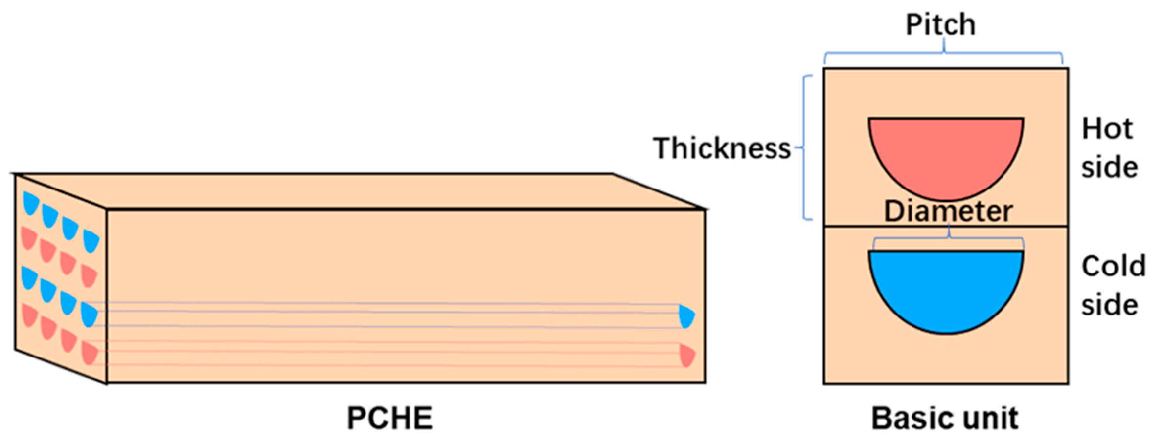
22]. The PCHE shown in
Figure 4 consists of alternating semicircular hot and cold channels embedded in a solid block. Hot fluid flows through the red channels, while cold fluid flows through the adjacent blue channels in a counter-flow arrangement. This setup maximizes the temperature gradient between the fluids, ensuring efficient heat transfer. The key parameters, such as channel diameter, pitch, and thickness, optimize heat exchange while maintaining a compact design. This efficient thermal management is crucial for maintaining the system’s overall performance.
For the recuperator, the cold side outlet temperature
, the solid structure temperature
, and the hot side outlet temperature
can be solved by the following equations, respectively:
For the precooler, the cold side outlet temperature
, the solid structure temperature
, and the hot side outlet temperature
can be solved by the following equations, respectively:
where
is the inlet temperature of the second side of the precooler, with a fixed value of 300 K.
In the above equations,
and
mean the equivalent heat transfer coefficient and heat transfer area of the PCHE channels. For instance, those parameters of the recuperator cold side with semicircle channels can be evaluated by the following equations [
4]:
where
is the convection heat transfer coefficient, which can also be evaluated by the D-B equation shown in Equation (7),
is the equivalent plate thickness, and
is the channel number of the recuperator cold side.
2.5. HeXe Pressure and Mass Calculation
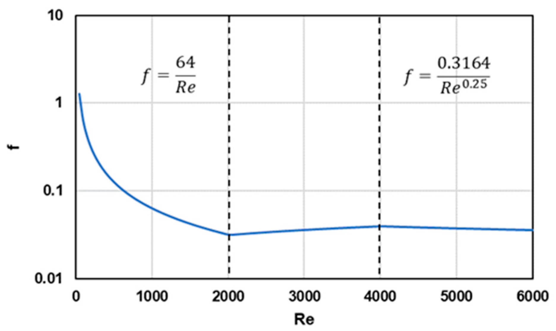
The pressure drop when the HeXe mixture flows through the reactor, the recuperator, and the precooler can be evaluated based on Darcy’s law:
where
is the hydraulic diameter of the channel, and f is the friction factor, which can be calculated by empirical correlations based on the flow
number, as shown in
Figure 5. Specifically, when the gas mixture flows at the transition region, a smooth linear interpolation of
is used to avoid possible divergence in the mass conservation iteration when conducting dynamic simulation.
For the closed cycle, the pressure values of different locations of the CBC can be determined if the pressure drop across components and the pressure ratio of the turbomachine have been obtained:
The total HeXe mass of the closed cycle can be calculated based on the state equations after the temperature and pressure of the gas mixture in different locations have been obtained:
where
is the gas constant of the HeXe mixture.
In addition, thermal properties of the solid materials are set as fixed values. Density of the air and the HeXe mixture will be updated based on state equations, and other thermal properties of the gas are also set as constants. For the HeXe mixture with the Xenon fraction of 12%, the specific heat, the thermal conductivity, and the dynamic viscosity are set as 1079 J/kg-K, 0.2471 W/m-K, and 5.91 × 10⁻⁵ Pa-s.
2.6. Dynamic Simulation Process
Table 1 lists the key unknown parameters of the nuclear-powered HeXe CBC and their corresponding equations, based on the modeling framework presented in the above contents. These equations are combined and can be treated by the Python ODE solvers. Therefore, the reactor core nuclear power as well as the temperature distributions of the CBC can be determined in dynamic simulations.
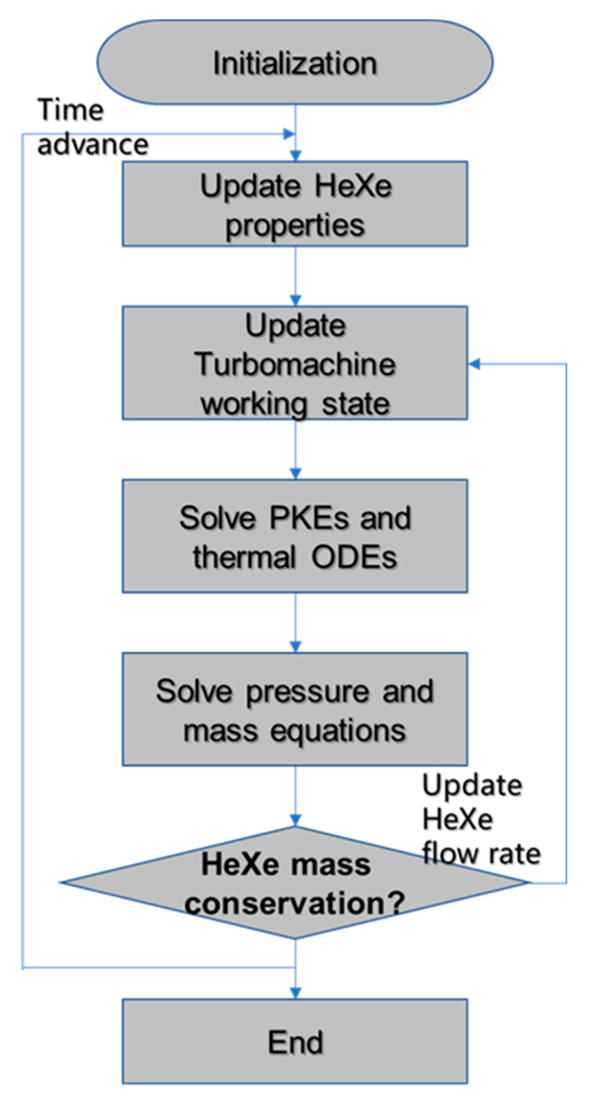
The dynamic simulation process is shown in
Figure 6. At each time step, the properties of the HeXe mixture are updated, followed by recalculating the turbomachinery working conditions. The PKEs and thermal ODEs are then solved to assess the reactor’s nuclear and thermal behavior. Next, the pressure and mass equations are solved to maintain system balance. A key step in the process is checking whether the HeXe flow rate satisfies the mass conservation criterion:
where
is the initial HeXe mass inside the cycle, and
is the tolerance which controls the convergence of the iteration. If the criterion is not met, the flow rate is updated, and the simulation loop returns to adjust the turbomachinery state accordingly. This iterative process continues until mass conservation is achieved, advancing to the next time step.
3. Result and Discussion
The developed programs are used to simulate the dynamic operating processes of the nuclear-powered HeXe CBC system. In this paper, a start-up process lasting 1500 s is chosen as the classical case. Firstly, parameter settings are given. Next, variation in the HeXe mass during the simulation is presented to prove the correctness and reliability of the program. Then, involution of the key thermohydraulic parameters of the system during start-up is demonstrated and analyzed.
3.1. Case Setting
The geometric parameters of the power system components are outlined in
Table 2. The reactor core has a length of 1 m, with key dimensions including a core radius of 0.44 m and a fuel-to-coolant pitch of 15 mm. The cladding thickness is set at 0.5 mm to ensure thermal and structural integrity. For the heat exchangers, both the recuperator and precooler are modeled as PCHE. The recuperator has a channel diameter of 1.5 mm and consists of 480 channels per layer, with a total of 1346 layers. The precooler has a channel diameter of 3 mm, with 361 channels per layer and 880 layers overall. These configurations are designed to optimize heat transfer efficiency and compactness, which is essential for a high-performance system.
For the start-up simulation, the initial conditions are listed in
Table 3. The reactor begins with an initial thermal power of 20 kWt, approximately 1/1000 of its rated power, to ensure a controlled start. The initial shaft speed is set to 1/100 of the rated value. The initial HeXe flow rate is set to 1/100 of the rated value, corresponding to 0.6 kg/s, and the air flow rate is similarly reduced to 1/100 of its rated 70 kg/s. The system starts at an initial temperature of 300 K, simulating ambient conditions before the reactor heats up. Additionally, the initial HeXe pressure is set at 0.7 MPa to match expected operational conditions. These conservative settings are chosen to allow for a gradual ramp-up of the system, ensuring safe and stable operation as the simulation progresses toward full power. This approach helps analyze the system’s response to start-up transients and its ability to reach a steady operational state. The total start-up simulation time is expected to be within 1500 s under the single time step of 0.5 s. Particularly, a tolerance
with the value of 0.01 kg is set to control the accuracy of the mass calculation, and the maximum mass conservation iteration per time step is set to 50 to avoid program freezes.
3.2. Code Verification
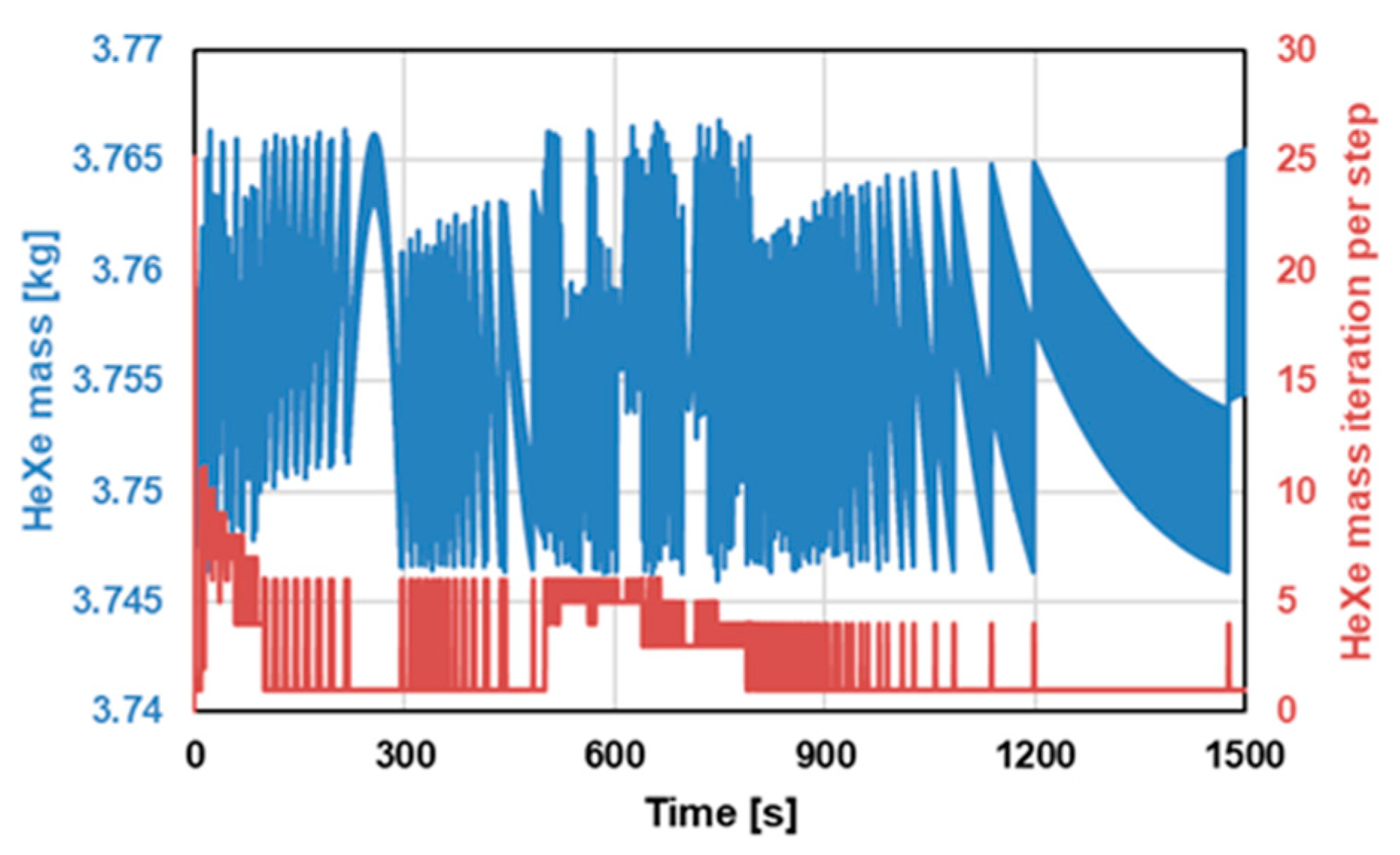
For code verification, the simulation results for the HeXe mass and the number of iterations required to maintain mass conservation over time are shown in
Figure 7. During the start-up process, the number of iterations per time step varies with a maximum of 25, which is greatly below the set limit of 50 iterations. The HeXe mass remains within the range of 3.755 ± 0.01 kg, meeting the tolerance level of 0.01 kg set for the simulation. This indicates that the mass conservation condition was consistently satisfied throughout the simulation, ensuring that each time step in the dynamic analysis converged successfully. Moreover, the decreasing number of iterations required as the simulation progresses further highlights the program’s efficiency in reaching mass conservation quickly as the system approaches steady-state conditions.
The verification results provide strong evidence for the reliability and accuracy of the developed dynamic simulation program. By successfully maintaining mass conservation under dynamic conditions, the program proves its robustness in handling the complexities of a HeXe-cooled reactor system. This ensures confidence in its ability to perform accurate simulations even during rapid changes in operational conditions, such as system start-up, shutdown, and other typical but complicated cases.
3.3. Start-Up Analysis
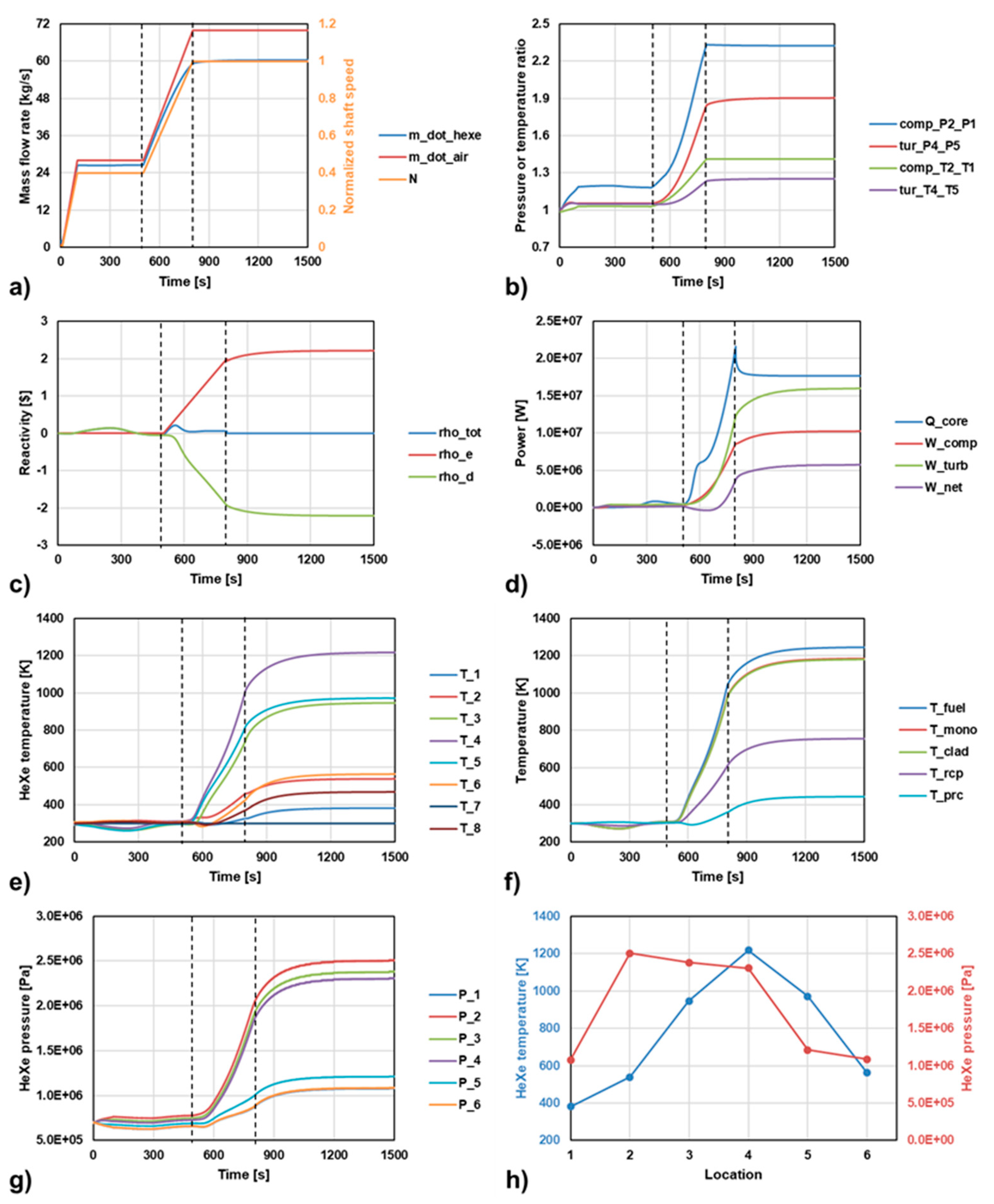
Figure 8 presents the simulation results of the system start-up process, demonstrating the evolution of key parameters over time. This process can be divided into three distinct phases: Phase 1 (0–500 s), Phase 2 (500–800 s), and Phase 3 (800–1500 s), each representing a critical stage in the system’s gradual transition to full operation. These subplots track parameters such as mass flow rate, shaft speed, pressure ratios, reactivity, power output, and HeXe temperatures throughout the start-up. These graphs provide insights into how the system components, such as the turbomachinery, compressor, and reactor, interact dynamically during the start-up process. Additionally, plot (h) illustrates the steady-state temperature and pressure distributions across key points in the system once the start-up phase is complete. This figure highlights the operational states of the CBC at full power, offering a comprehensive view of how the system achieves equilibrium.
Overall, the start-up strategy can be concluded as starting the CBC first at the first 500 s, followed by starting the nuclear reactor by inserting some external reactivity at 500–800 s.
In Phase 1 (0–500 s), the system begins its initial start-up. Within the first 100 s, both the shaft speed
and the air mass flow rate
rapidly increase to approximately 40% of their rated values. According to the HeXe mass conservation results, the HeXe mass flow
stabilizes at around 26 kg/s. As shown by the characteristic curves, the compressor pressure ratio gradually increases and stabilizes at around 1.19. During this phase, the external reactivity
is kept at 0, and the reactor does not actively initiate fission reactions. Notably, despite the absence of nuclear heat generation, the HeXe mixture flows and expands through the turbine, causing the system’s temperature to slightly drop by approximately 35 K [
17]. Based on the temperature feedback effect, this temperature drop leads to a slight positive reactivity
, which in turn causes a passive and minor increase in nuclear reactor power output, reaching around 0.8 MWt. In terms of pressure, the HeXe loop pressure remains almost unchanged at approximately 0.7 MPa.
In Phase 2 (500–800 s), the external reactivity is actively increased linearly from 0 to approximately USD 2. As a result, the power output and temperature of the solid-state reactor rise rapidly. With the reactor core temperature gradually reaching 1000 K, the negative reactivity also increases gradually, and the total reactivity approaches zero. During this phase, the nuclear power output reaches approximately 20 MWt. To match the rising thermal output, both shaft speed and the air mass flow rate are increased from 40% to 100%. The HeXe mass flow gradually rises to 60 kg/s, while the compressor pressure ratio increases to around 2.3, and the turbine pressure ratio rises to approximately 1.9. As shown in subplot (g), the pressure differential across the loop becomes evident, with a high pressure of around 2 MPa at the compressor outlet and a low pressure of about 1 MPa at the turbine inlet. Notably, from 500 to 700 s, the work consumed by the compressor is larger than that produced by the turbine, thus the system’s net output power is negative. After 700 s, the system output power is positive and rises steadily, indicating that the system is transitioning smoothly toward full operation.
In Phase 3 (800–1500 s), the shaft speed
and the gas mass flow rates are maintained at 100%, while the external reactivity
is controlled to follow the variation in the temperature feedback reactivity
, causing the net reactivity
to be equal to 0. The system’s nuclear power output stabilizes at around 18 MWt, while the net output power of the CBC stabilizes at approximately 5.7 MWe, hence the overall thermal efficiency of the entire system reaches about 32.5%. The cycle effectiveness is determined by the design requirement of the mobile power system. The CBC effectiveness of the Prometheus project is 27% [
17]. Hence, the calculated effectiveness by the dynamic start-up simulation in our system is reasonable. Subplot (h) shows the steady-state temperature and pressure distributions across the CBC loop. The whole loop can be clearly divided into high-pressure sections (point 2-3-4) and low-pressure sections (point 5-6-1). The maximum pressure is observed at the compressor outlet (point 2), reaching about 2.5 MPa, while the lowest pressure is at the turbine inlet (point 1), at approximately 1.07 MPa. The flow pressure loss across the nuclear reactor and the recuperator is larger than that across the precooler having a shorter length. The temperature differences between the reactor core and the recuperator are evident, with the highest temperature at the turbine outlet (point 4) reaching about 1200 K, and the lowest temperature at the compressor inlet (point 1) reaching around 400 K. The recuperator’s internal temperature (between points 2 and 3) increases to about 407 K, significantly indicating the importance of the recuperator on enhancing the overall system efficiency. Notably, the temperature of the exhaust gas after passing through the secondary air cooler is still relatively high at 468 K, providing potential for further utilization, such as in an organic Rankine cycle (ORC) to improve overall system efficiency. With such energy recovery methods, the system’s overall performance can be further optimized.
The conducted dynamic simulation results of the HeXe-cooled CBC system are compared with the published ones of the Prometheus project [
17]. The design schemes of these two systems are quite similar by using the HeXe-cooled CBC configuration. In this MW-level land-based system, the low-enriched nuclear fuel and the graphite moderator is used for the reactor core, and the air-cooled pre-cooler is used as the heat sink. In the kW-level Prometheus space nuclear power system, the reactor is featured with a fast spectrum, and the radiation heat exchanger is used as the heat sink in the space environment. The mentioned differences about the system designs can lead to different point kinetic parameters and heat sink performance during the dynamic simulations. However, both the dynamic simulation codes are developed based on the lumped model and the law of mass and energy conservation. The overall tendencies of the start-up process and the evolution of cycle thermohydraulic parameters are similar.


