Article

Influence of Ti Layers on the Efficiency of Solar Cells and the Reduction of Heat Transfer in Building-Integrated Photovoltaics

by
Paweł Kwaśnicki
1,2,*,
Dariusz Augustowski
1,
Agnieszka Generowicz
3,* and
Anna Kochanek
4
1
Research & Development Centre for Photovoltaics, ML System S.A., Zaczernie 190G, 36-062 Zaczernie, Poland
2
Faculty of Natural and Technical Sciences, John Paul II Catholic University of Lublin, Konstantynów 1H, 20-708 Lublin, Poland
3
Department of Environmental Technologies, Cracow University of Technology, 31-155 Kraków, Poland
4
Faculty of Engineering, State University of Applied Sciences in Nowy Sącz, 33-300 Nowy Sącz, Poland
*
Authors to whom correspondence should be addressed.
Energies 2024, 17(21), 5327; https://doi.org/10.3390/en17215327
Submission received: 15 September 2024 / Revised: 18 October 2024 / Accepted: 23 October 2024 / Published: 25 October 2024

Abstract

:
This study examined the potential application of metallic coatings to mitigate the adverse effects of ultraviolet (UV) and infrared (IR) light on photovoltaic modules. Titanium coatings were applied on low-iron glass surfaces using magnetron sputtering at powers of 1000, 1250, 1500, 1750, 2000, and 2500 W. The module with uncoated glass served as a reference. The Ti layer thickness varied from 7 nm to 20 nm. Transmittance and reflectance spectra were used to calculate visible light transmittance Lt, UV light transmittance Ltuv, solar transmittance g, and visible light reflectance Lr. The obtained parameters indicated that the thinnest Ti layer (1000 W) coating did not significantly affect light transmittance, but thicker layers did, altering the Lt, g, and Lr factors. However, every sample noticeably changed Ltuv, probably due to the natural formation of a UV-reflective thin TiO2 layer. The differences in fill factor (FF) were minimal, but thicker coatings resulted in lower open-circuit voltages (Uoc) and short-circuit currents (Isc), leading to a reduction in power conversion efficiency (PCE). Notably, a Ti coating deposited at 2500 W reduced the power of the photovoltaic module by 78% compared to the uncoated sample but may protect modules against the unwanted effects of overheating.

1. Introduction

The changing requirements of the EU introduce the need for increasingly efficient technological solutions in the energy industry [1,2]; energy generation must be in line with the circular economy [3,4]. High-efficiency photovoltaic systems have become crucial in modern times, where the EU places significant emphasis on the decarbonization of the energy system [5,6]. One of the key elements affecting the efficiency of second- and third-generation photovoltaic cells is the presence of transparent conductive oxide (TCO) layers, which are essential components influencing the performance and durability of solar panels [7]. Photovoltaic technology is developing rapidly compared to other renewable energy sources, and building-integrated photovoltaic (BIPV) systems play an important role in generating electricity [8]. BIPVs are an efficient way to produce renewable energy on-site while meeting architectural requirements and providing one or more functions of the building’s external envelope [9].
Photovoltaic modules are considered building-integrated if the photovoltaic modules form a construction product that performs a function according to the definition contained in the European Construction Products Regulation CPR 305/2011. Therefore, a BIPV module is a prerequisite for the integrity of the building’s functionality [10]. Today’s BIPV market is relatively small, and the prices of BIPV façade products are high compared to non-BIPV façades. The high prices of BIPV modules are a major obstacle to stronger growth. One of the main components of BIPV modules is the solar cell. The prices of solar cells have decreased in recent years, making BIPVs based on crystalline silicon solar cells much cheaper today. Another reason why BIPV modules are expensive is the poor automation of manufacturing plants [11].
BIPV modules have specialised features compared to standard PV modules to better meet architectural and construction requirements. A simple BIPV module design consists of a PV laminate resulting from the combination of the following layers: front cover/front sheet/encapsulant/photovoltaic cells/encapsulant/back cover (backsheet). The most popular encapsulating materials are ethylene-vinyl acetate (EVA) and polyvinyl butyral (PVB). Both the front and back covers are made of glass, making the structure a PV–glass laminate (PVGL), similar to any other glass–glass laminate (GL) but with photovoltaic cells in the middle. The specification of both glass sheets along with the encapsulant will determine the mechanical properties of the laminate [12].
The most commonly used cell technology is crystalline silicon (c-Si), both multicrystalline (mc-Si) and monocrystalline (sc-Si). Amorphous silicon (a-Si) is also widely used due to its high versatility in producing modules on various substrates and in different sizes, shapes, and degrees of transparency [11]. For in-depth thermal studies of BIPV modules and systems, energy balance equations expressing heat transfer phenomena can be applied [13]. In many cases, these numerical models take into account the thermal capacity of the glass, cells, and frame [14,15].
With the development of the BIPV system, the building-integrated photovoltaic/thermal (BIPV/T) system has emerged, utilizing the building envelope to collect solar energy to produce both electrical and thermal energy, effectively reducing the building’s energy consumption [16]. The BIPV/T system captures solar radiation using either a flat surface or a refractive–reflective concentrating device [17]. A range of media, including air, water, and refrigerants, can be used to cool the photovoltaic installation [18]. Air-based BIPV/T systems can achieve optimal performance if they have ideally designed features, such as tilt angles, configuration layouts, and fluid flow rates selected correctly [19].
Considering the performance of various BIPV cells, the impact of climate on some BIPV technologies, such as dye-sensitised solar cells (DSSCs) and organic solar cells (OSCs), is significantly more pronounced than on others. In climates with higher diffuse radiation—or with more cloudy days per year—the share of IR radiation decreases [20,21]. Different BIPV technologies have different spectral responses to the incident solar radiation and its components [22,23]. Wang et al. presented high-performance semi-transparent organic solar cells (ST-OSCs) with excellent power generation characteristics, being transparent and reflecting infrared heat, with promising prospects for BIPV [24]. Semi-transparent organic solar cells (ST-OSCs) show promising features as building-integrated photovoltaic (BIPV) cells [25]. In recent years, significant progress has been made in ST-OSCs, with the development of near-infrared (NIR) absorbers and semi-transparent device architecture [26].
Ouellette et al. stated that adjusting the reflection coefficient and central wavelength of the front mirror, as well as the thickness of the active layer, allowed for a total increase in absorption by 56% in the infrared range, leading to a record external quantum efficiency of 60% at 1300 nm [27]. Titanium is a lightweight and relatively cheap metal. It is often used in industry because of its hardness [28], high mechanical strength [29], and corrosion resistance [30]. For this reason, it is often used in the form of thin layers on various components for applications such as aerospace engineering [31], medicine [32], and automotive engineering. Titanium and its alloys are resistant to both high [33] and low [34] temperatures. Like aluminium, it undergoes natural passivation, which means that a several-nanometres-thick titanium(IV) oxide layer forms on its surface and blocks the migration of oxygen deep into the coating [35]. In the event of mechanical scratching, passivation occurs again, so that corrosion of the metal is spontaneously blocked. The chemical stability of titanium allows its use in medicine. Due to its bioinertness, it does not lead to inflammatory or allergic reactions when in contact with biological tissues or skin, making it a commercially applicable metal for use as a prosthetic material [36]. Titanium stands out as a kind of environmentally friendly metal, as it has low environmental impact [37] and is easy to recycle [38].
The titanium coating is durable, thanks in part to its low thermal expansion [39], which ensures that the coating does not flake under fluctuating temperatures. In addition, its deposition is simple thanks to the deposition process involving magnetron sputtering of the metal in a vacuum (PVD method) [40,41], which is a fast solution that provides high precision in controlling the thickness of the layer and its uniformity. An additional advantage of the coatings is the oxide present on them. As previously mentioned, the TiO2 layer forms spontaneously. If used on the outer position of the PV panel, it exhibits an antimicrobial effect [42,43], so bacteria and fungi do not grow on it. When used in architecture as an external coating, this is of great importance, as it results in a reduced or even complete reduction in the growth of algae and fungi that form unsightly green growth facades [44].
Depending on the thickness of the titanium layer on the glass, the coating changes its colour to grey or silver. This colour is permanent over time, even after exposure to the weather. Other commercially available and inexpensive metals, such as copper, can change the colour of the glass, so may result in less market interest. The anti-corrosive properties of titanium also protect the underlying surface from external agents, thus inhibiting corrosion and tarnishing of the glass. The Ti layer can be deposited on different types of glass: plain, matt, flat, or structured. Increasing the thickness of the coating leads to an increasing degree of grey. However, beyond a certain value, a mirror effect is created [45]. Such a layer, due to increased reflectivity, prevents light from passing through to the PV panel’s interior, where the solar cells are located. On the other hand, a well-optimised thickness of the titanium layer would be a great advantage, as it would prevent the light-induced degradation of the lamination foil, just like the silicon solar cell itself. Additionally, a thin metal film deposited on the glass reflects some of the infrared light [42], which could solve the problem of PV modules overheating in an environment with very high solar radiation, such as equatorial countries [46].
In the current study, we tested thin titanium layers as the passive protective coatings for photovoltaic modules with the glass–glass laminate architecture widely used in BIPV systems. By applying these coatings, the internal components of the module could be protected from the negative effects of solar radiation, especially UV and IR, which, as mentioned above, may be particularly harmful to solar cells and other elements. Ti coatings were applied directly to the glass substrate with different sputtering powers and characterised by methods such as profilometry and spectrophotometry. According to the data obtained, the thicknesses of each coating were calculated and optical properties (transmittance and reflectance) were analysed. The finished modules were then characterised by current-voltage measurement to evaluate the power losses caused by each layer type. Finally, temperature functions were determined from the time of the exposed modules to assess the degree of heating under standard solar conditions.

2. Materials and Methods

2.1. Materials

Glass sheets (low-iron) were obtained from ESG (Witham, UK). The lamination foil used in this study was PVB, which is commercially available from DuPont (Wilmington, DE, USA). Its thickness was 0.76 mm. Titanium layers were deposited by magnetron sputtering from rectangular Ti target (99,99% pure, 1397 × 127 × 6 mm3, Kenosistec, Casarile, Italy).

2.2. PV Module Fabrication

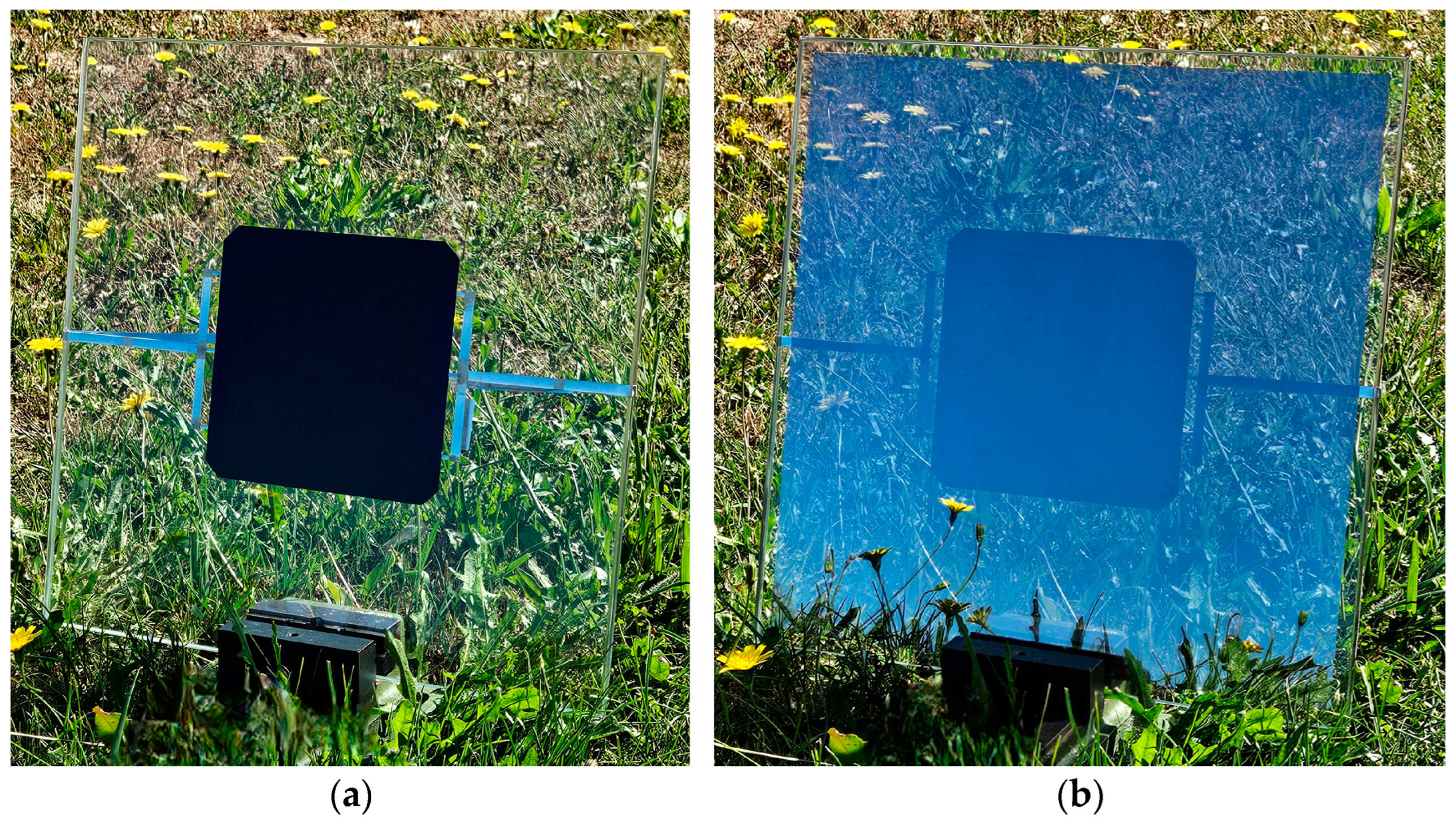
Each photovoltaic module (see Figure 1) was constructed from the following materials in a sandwich-like structure: glass sheet (300 × 300 × 4 mm3), titanium coating, lamination film (PVB), silicon solar cell with ribbon busbars, lamination film (PVB), and glass sheet (300 × 300 × 4 mm3). The 4 mm glass was chosen in the following test because it is typically used in commercially available PV modules due to its favourable weight-to-mechanical strength ratio [47]. The Ti coating was deposited on the glass surface by a magnetron sputtering method with different thickness values. On both sides of the silicon solar cell, a lamination film of 0.76 mm thickness was used to seal it between two sheets of glass during the lamination process held at a temperature of 160 °C for 1 h. Two ribbons were extended to the outside to allow current-voltage measurements.

2.3. Methods

Titanium coating was deposited on the glass surface by the magnetron sputtering method by KS 1800 H In-line PVD system (Kenosistec, Italy). The process was carried out with different sputtering powers: 1000, 1250, 1500, 1750, 2000, and 2500 W from Ti target to obtain different layer thicknesses. Based on this, the power density could be calculated: 0.56, 0.70, 0.85, 0.99, 1.13, and 1.41 W/cm2. Before the deposition, glass substrates were cleaned in isopropanol and then degassed in the vacuum chamber at a temperature of 180 °C for 3 min. These steps are crucial to obtain uniform and well-adhered coatings. The titanium-coated glass samples prepared by this method were characterised by UV-VIS-NIR spectrophotometer (V-670, Jasco, Tokyo, Japan). Transmittance and reflectance spectra were measured in the range from 200 to 2500 nm and optical parameters were calculated by Spectra Manager software (ver. 2.14.01, Jasco, Japan). The thickness of each layer, prepared with different sputtering powers, was measured by stylus profilometer (DektakXT, Bruker, Billerica, MA, USA). After the lamination process, the prepared photovoltaic modules were also characterised by current-voltage measurements (CLASS-01, PV Test Solutions, Wrocław, Poland) to obtain the photovoltaic parameters for samples with various layer thicknesses and the module with uncoated glass as a reference sample. The examples of completed modules are shown in Figure 2. The image of each titanium layer obtained by scanning electron microscope (SEM, Regulus 8230, Hitachi, Tokyo, Japan) were presented in Supplementary Materials.

3. Results

3.1. Titanium Layer Thickness

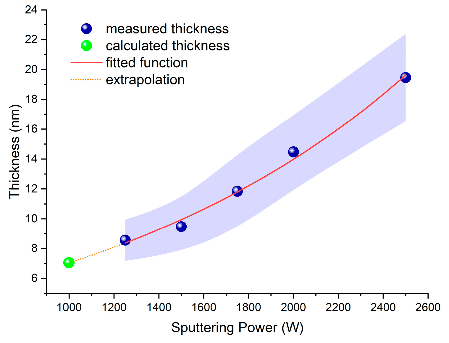
A stylus profilometer was used to measure the thickness of the titanium layer on the glass. According to data obtained, layers prepared with sputtering powers of 1250, 1500, 1750, 2000, and 2500 W were 8.6 ± 1.4, 9.5 ± 1.7, 14.5 ± 2.4, 11.8 ± 2.5, and 19.5 ± 2.9 nm thick, respectively. The purple area presented in Figure 3 shows the measurement uncertainty, which was calculated as a standard deviation for five measurements for each sample. We were unable to measure the thickness of coating prepared with the power of 1000 W; thus, we decided to fit the following exponential function:
d T i = A e B P m a g + d 0 ,
d T i = 3.76 e 6.67 · 10 4 P m a g 0.27 ,
where dTi is the titanium thickness; Pmag is the sputtering power; and A = 3.76 nm, B = 6.67·10−4 W−1, d0 = −0.27 nm are function parameters, which were determined by function fit in OriginLab (ver. 2024b, OriginLab Corporation, Northampton, MA, USA). The formula obtained was used to estimate the titanium thickness for the sputtering power of 1000 W, which was 7.1 nm. According to these data, we can assume that the Ti thicknesses varied from 7 to 20 nm.

3.2. Optical Parameters

Optical characterization was carried out by spectrophotometer in the range of 200–2500 nm, which is necessary to calculate optical parameters such as visible light transmittance Lt, UV light transmittance Ltuv, solar transmittance g, and visible light reflectance Lr. They are given by the following equations:
L t = λ τ λ   D λ   V λ Δ λ λ D λ   V λ Δ λ ,   for   λ   from   380   to   780   nm ,
L t u v = λ τ λ   U λ Δ λ λ   U λ Δ λ   ,   for   λ   from   300   to   380   nm ,
g = λ τ λ   E λ Δ λ λ E λ Δ λ   ,   for   λ   from   300   to   2500   nm ,
L r = λ ρ λ   D λ V   λ Δ λ λ D λ   V λ Δ λ   ,   for   λ   from   380   to   780   nm ,
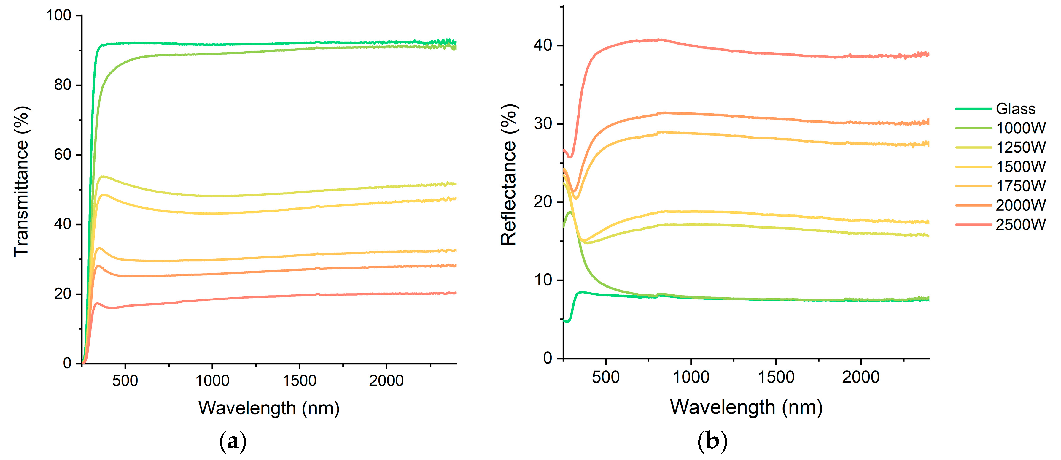
where τ(λ) is a transmittance, Dλ is the spectral distribution at CIE illuminant D65, V(λ) is the CIE standard photopic luminous efficiency, Uλ is the UV-relative spectral distribution, Eλ is the solar relative spectral distribution, and ∆λ is the wavelength interval. Parameters were determined from the acquired transmittance and reflectance spectra, which are shown in Figure 4.
The parameters of each sample were tabularised in Table 1. Light transmittance was highest for the uncoated glass sample. The value of 92% is typical for glass with a low iron concentration [48]. Deposition of the titanium coating decreases the sample transparency. For the low-power sputtering process (1000 W), the calculated Lt was 88%. However, subsequent samples, prepared with higher powers, had significantly lower light transmittance, which was clearly visible on the spectra. The obtained Lt parameters for the sputtering powers of 1250, 1500, 1750, 2000, and 2500 W were 51, 45, 30, 25, and 17%, respectively. The noticeable difference between 1000 and 1250 W could be the result of the total metal oxidation process for the thinner coating.
According to other studies [49], the surface of titanium oxidises immediately upon exposure to air. The initial oxide layer is about a few nanometers thick, but if the titanium layer is only 7.1 nm thick, the entire layer can be oxidised. The presence of TiO2 could be confirmed by reflectance spectra. For the sample prepared with the power of 1000 W, the difference between this sample and the uncoated glass was negligible in the visible and infrared region. But in the UV region, the characteristic peak was observed. Its maximum was located at 290 nm, which certainly corresponds to TiO2’s optical band gap, which is ca. 3.2 eV [50]. The same peak was also present in other reflectance spectra but was slightly shifted and overshadowed by the increasing reflection. Obviously, the increasing reflectance Lr was due to the presence of an increasingly thick metallic coating, which caused a mirror effect in the sample prepared with the sputtering power of 2500 W.
The trend for the g-factor was similar to that for the Lt. Only a slight difference was observed between the uncoated glass and the sample prepared with 1000 W (92 and 88%, respectively), but further sputtering powers had significantly higher differences. For 1250 W, it was 56%, and for 2500 W, it was just 26%, which means that for the Ti thickness of 20 nm, about 75% of the light power was attenuated. It is noticeable that UV light transmittance was significantly lower for the 1000 W sample than for uncoated glass, which performed differently from other parameters. This indicates that such a thin layer reduces the UV radiation, which is harmful to PV module, because it may cause damage to the silicon solar cell [49] and the PVB lamination foil [50] and accelerate their degradation process. On the other hand, it does not significantly reduce the amount of visible and infrared light entering the device, enabling it to achieve a high solar-to-electricity conversion ratio.

3.3. Photovoltaic Parameters

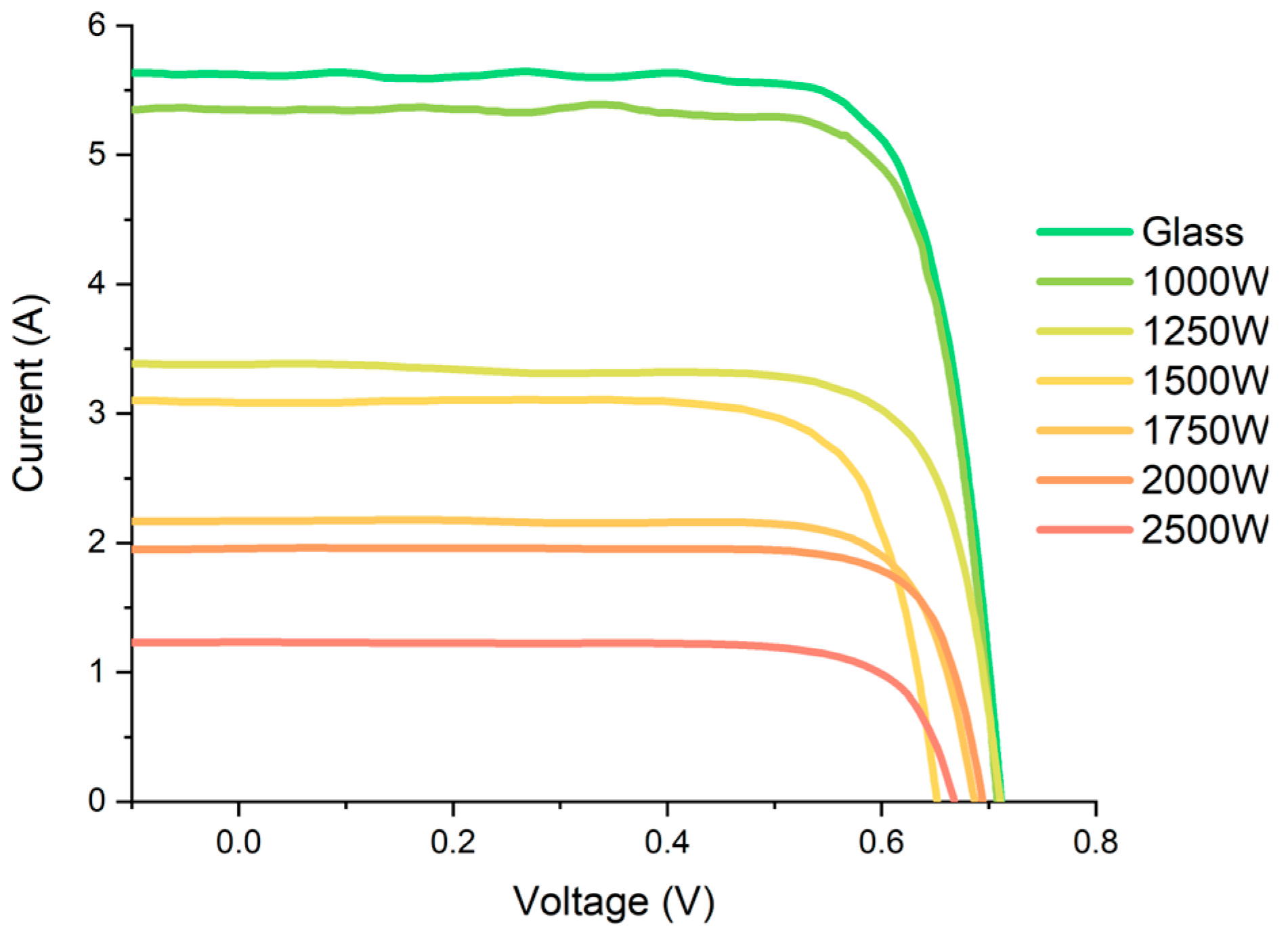
After the characterisation of titanium coatings, the glass sheets were laminated with other elements of the PV module. Electrical measurements of the finished modules were possible due to the electrical leads on the sides of each module. Current-voltage characteristics were acquired under AM1.5 illumination, the standard solar spectrum with a power density of 1 SUN = 1000 W/m2. The obtained curves are presented in Figure 5. Three samples were fabricated and characterised for each thickness for better statistics and to assess the process repeatability.
The calculated photovoltaic parameters with calculated errors are shown in Table 2. As presented, open-circuit voltage Uoc decreases when the thickness of titanium coating increases. This was certainly caused by lower solar illumination power. According to other studies, the irradiance could have an impact on Uoc [51,52], especially when the temperature of the solar cell increases [53,54]. Thus, the highest value was observed for the PV module with uncoated glass, and the lowest for the module with the thickest Ti layer. They were 712 and 668 mv, respectively—a drop of around 6%. However, a deviation appeared for this parameter that was determined for a module prepared for 1500 W. The most significant difference was observed for short-circuit current Isc. In this case, the decrease for the uncoated glass and the thickest Ti layer was 77%. The value of each sample was 5.61, 5.36, 3.12, 3.04, 2.33, 1.91, and 1.27 A for the uncoated glass and the 1000, 1250, 1500, 1750, 2000, and 2500 W coatings, respectively. This clearly shows how the nano-sized titanium coating relevantly reduces the solar irradiance and affects the performance of the PV module.
The fill factor FF values did not differ significantly from one another, indicating that the Ti layer did not interfere with the solar cell itself. Its value was in the range from 0.769 to 0.794. The overall performance of the PV modules, measured in terms of power conversion efficiency PCE, was as follows: 19.8, 18.8, 10.6, 9.9, 7.8, 6.8, and 4.2% for the uncoated glass and the 1000, 1250, 1500, 1750, 2000, and 2500 W coatings, respectively. There was a slight decrease in efficiency between the uncoated glass and the sample prepared with the sputtering power of 1000 W. However, the layer prepared with the power of 1250 W reduces the PCE significantly by about 46% (compared to the reference module). As shown in Figure 6, the changes observed for successive titanium layer thicknesses were much smaller.
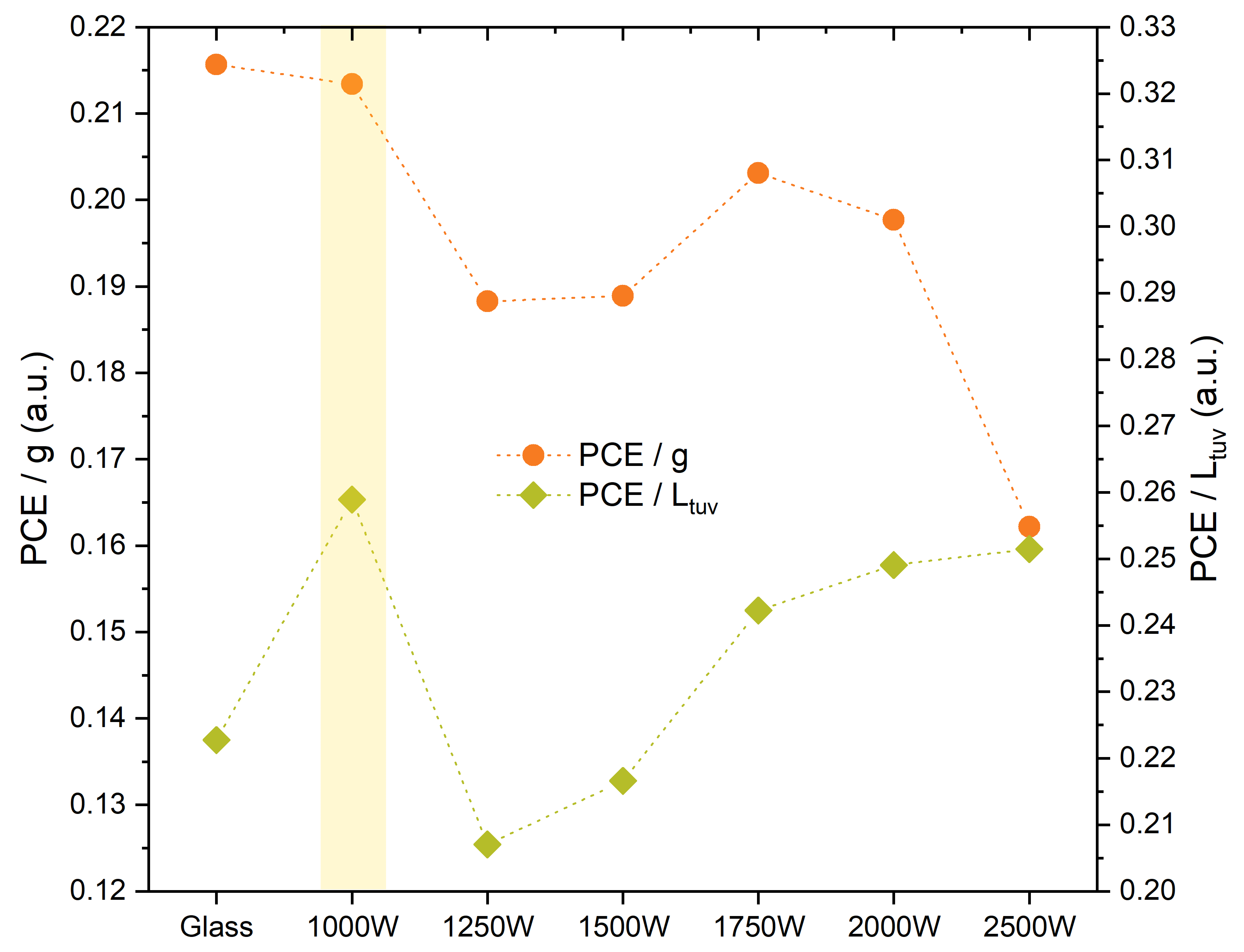
A comparison of the electrical and optical results is shown in Figure 7. The parameters compared were PCE with g and PCE with Ltuv. In the latter case, the best results were observed for the titanium coating prepared with a sputtering power of 1000 W, which was observed as the highest ratio of PCE to Ltuv (ca. 0.26). Elsewhere, the ratio was noticeably lower, indicating that the 1000 W PV modules provided the best UV protection with a very good module efficiency. In the case of the PCE/g ratio, the highest value was received for the PV module with uncoated glass, which was predictable due to high light power transmittance. However, across the modules with titanium coatings, the best performance was also observed for the sputtering process of 1000 W. High solar energy transmission ensured the high efficiency of the solar cell. But UV light is not the only harmful radiation for PV modules. In regions with strong radiation, such as the Algerian desert [55,56], where IR light is abundant, increased degradation is observed due to, among other things, the overheating of photovoltaic devices. This process may be observed as module delamination, the rapid decline of its performance, or even cracking of the silicon solar cell. For this reason, the choice of the appropriate coating should be dictated by local sunlight conditions. It might be preferable to reduce the module efficiency by using a thicker titanium coating while extending the lifetime of the PV module. Such a test should be carried out in situ in countries with different climates, because, in addition to solar conditions, air humidity, altitude, or diurnal temperature variation are also very important factors.

3.4. Temperature Control

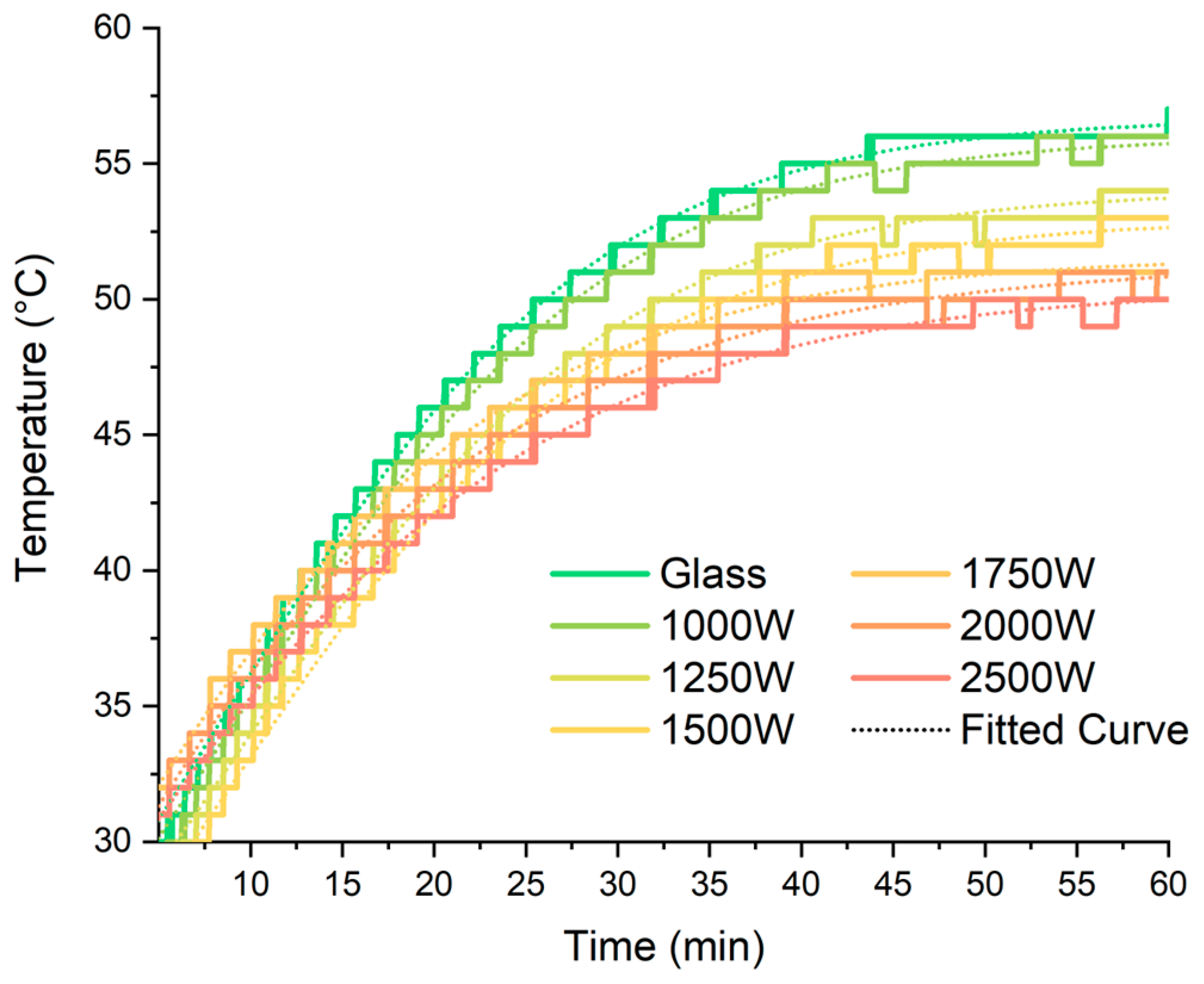
The heating process of the modules was examined under a 1 SUN illumination. The thermocouple was attached to the glass behind the solar cell. The measurement lasted one hour, as shown in Figure 8. To the data obtained, the following function was fitted
T = T 1 T 2 1 + e t t 0 τ + T 2
where T1 and T2 are minimum and maximum temperatures, t0 is the function-centring parameter, and τ is a time constant. The calculated parameters are summarised in Table 3. In the case of the uncoated glass, the maximal temperature was the highest and equal to 56.7 °C. For modules with the Ti coatings, Tmax were 56.0, 54.0, 53.0, 51.6, 51.4, and 50.5 °C for 1000, 1250, 1500, 1750, 2000, and 2500 W coatings, respectively. The difference between the uncoated and coated modules with a power of 2500 W was 6.2 °C, which is a significant difference in photovoltaic systems, which can increase the durability of solar cells and entire laminates under very intense sunlight conditions. However, a difference in temperature was observed even with thinner coatings. This shows that the titanium coating can be used as a passive cooling system for the modules. Besides protecting against high temperatures, this solution reduces the heating rate of the modules, as shown by the decreasing τ−1 factor. This may protect the cells from sudden temperature increases when there is a sudden change in sunlight, e.g., after rain. The value of τ−1 was almost equal for the uncoated glass and 1000 W module (1.64·10−3 s−1 and 1.65·10−3 s−1, respectively), but dropped to 1.18·10−3 s−1 for the 2500 W coating.

4. Conclusions

An investigation was carried out into the possibility of using metallic titanium coatings to reduce the damaging effects of light on photovoltaic modules. Ti coatings were deposited on the low-iron glass by the magnetron sputtering method with sputtering powers of 1000, 1250, 1500, 1750, 2000, and 2500 W. One module was prepared with uncoated glass as a reference sample. The thickness of Ti layer ranged from 7 nm for the lowest power to 20 nm for the highest sputtering power. According to the transmittance and reflectance spectra, we suggest that the 1000 W layer was totally oxidised due to the characteristic behaviour in the UV range. Optical parameters, calculated on the basis of collected spectra, showed that the 1000 W coating did not change the light transmittance significantly, but the subsequent layers did, which was observed for the Lt, g, and Lr factors. In the case of Ltuv, a noticeable change was observed even for the thinnest Ti layer. This could be caused by the formation of the TiO2 layer, known for its good ability to reflect UV light. Only a slight difference between the samples for the FF values was measured, but the thicker the titanium layer, the lower the observed Uoc and Isc were. This was very significant for the latter, and caused a noticeable reduction in the PCE. For example, the Ti coating prepared with the sputtering power of 2500 W dropped the power of the PV module by 78% (compared to uncoated glass).
There is no clear answer as to which coating is the best. It depends on where the photovoltaic installation is used. For instance, at high attitudes, where the intensity of UV light is above average but the temperature is moderate, we suggest it is best to use a thinner coating due to its ability to reflect UV light and provide high power conversion efficiency. However, under desert conditions, it may not be enough to provide a long-lasting life for PV modules. In such a case, a thicker titanium coating should be used to protect the inner components from degradation and overheating caused by UV and IR radiation. We suggest that the layer prepared with the sputtering power of 1250 W may be the most useful. In this study, it reduced the PCE by about 42%, but also significantly reduced the solar energy transmittance (g factor equal to 56%) and the temperature of the PV module by 2.7 °C.

Supplementary Materials

The following supporting information can be downloaded at: https://www.mdpi.com/article/10.3390/en17215327/s1, Figure S1. SEM images of the titanium layers prepared with different sputtering powers.

Author Contributions

Conceptualization, P.K.; methodology, D.A., A.G. and P.K.; formal analysis, D.A. and A.K.; investigation, D.A.; resources, A.G.; data curation, D.A.; writing—original draft preparation, D.A.; writing—review and editing, A.G. and A.K.; visualization, D.A.; funding acquisition, P.K. All authors have read and agreed to the published version of the manuscript.

Funding

Work carried out as part of the project: QDrive—Innovative active glass for the automotive industry (01.01.01-00-1156/20).

Data Availability Statement

Data are contained within the article.

Conflicts of Interest

The authors declare no conflicts of interest.

References

  1. Barbusiński, K.; Kwaśnicki, P.; Gronba-Chyła, A.; Generowicz, A.; Ciuła, J.; Szeląg, B.; Fatone, F.; Makara, A.; Kowalski, Z. Influence of Environmental Conditions on the Electrical Parameters of Side Connectors in Glass–Glass Photovoltaic Modules. Energies 2024, 17, 680. [Google Scholar] [CrossRef]
  2. Bodziacki, S.; Malinowski, M.; Famielec, S.; Krakowiak-Bal, A.; Basak, Z.; Łukasiewicz, M.; Wolny-Koładka, K.; Atılgan, A.; Artun, O. Ocena środowiskowa modernizacji systemów energetycznych w budynkach użyteczności publicznej. Energie 2024, 17, 3278. [Google Scholar] [CrossRef]
  3. Generowicz, A.; Gronba-Chyła, A.; Kulczycka, J.; Harazin, P.; Gaska, K.; Ciuła, J.; Ocłoń, P. Life Cycle Assessment for the environmental impact assessment of a city’ cleaning system. The case of Cracow (Poland). J. Clean. Prod. 2024, 382, 135184. [Google Scholar] [CrossRef]
  4. Gronba-Chyła, A.; Generowicz, A.; Alwaeli, M.; Mannheim, V.; Grąz, K.; Kwaśnicki, P.; Kramek, A. Municipal waste utilization as a substitute for natural aggregate in the light of the circular economy. J. Clean. Prod. 2024, 440, 140907. [Google Scholar] [CrossRef]
  5. Kwaśnicki, P.; Gronba-Chyła, A.; Generowicz, A.; Ciuła, J.; Wiewiórska, I.; Gaska, K. Alternative method of making electrical connections in the 1st and 3rd generation modules as an effective way to improve module efficiency and reduce production costs. Arch. Thermodyn. 2023, 44, 179–200. [Google Scholar] [CrossRef]
  6. The Paris Agreement. Available online: https://unfccc.int/process-and-meetings/the-paris-agreement/the-paris-agreement (accessed on 1 September 2024).
  7. Kwaśnicki, P.; Gronba-Chyła, A.; Generowicz, A.; Ciuła, J.; Makara, A.; Kowalski, Z. Characterization of the TCO Layer on a Glass Surface for PV IInd and IIIrd Generation Applications. Energies 2024, 17, 3122. [Google Scholar] [CrossRef]
  8. Biyik, E.; Araz, M.; Hepbasli, A.; Shahrestani, M.; Yao, B.; Shao, L.; Essah, E.; Oliveira, A.C.; del Caño, T.; Rico, E.; et al. A key review of building integrated photovoltaic (BIPV) systems. Eng. Sci. Technol. Int. J. 2017, 20, 833–858. [Google Scholar] [CrossRef]
  9. Masson, G.; Kaizuka, I.; Bosch, E.; Detollenaere, A.; Neubourg, G.; van Wetter, J.; Lindahl, J. Raport IEA PVPS—Trends in Photovoltaic Applications 2020; The International Energy Agency: Paris, France, 2020. [Google Scholar]
  10. IEA PVPS Task 15 BIPV, International Definitions of BIPV, Report IEA-PVPS T15–04, August 2018. Available online: https://iea-pvps.org/wp-content/uploads/2020/02/IEA-PVPS_Task_15_Report_C0_International_definitions_of_BIPV_hrw_180823.pdf (accessed on 1 September 2024).
  11. Kuhn, T.E.; Erban, C.; Heinrich, M.; Eisenlohr, J.; Ensslen, F.; Neuhaus, D.H. Review of technological design options for building integrated photovoltaics (BIPV). Energy Build. 2021, 231, 110381. [Google Scholar] [CrossRef]
  12. Martín-Chivelet, N.; Kapsis, K.; Wilson, H.R.; Delisle, V.; Yang, R.; Olivieri, L.; Polo, J.; Eisenlohr, J.; Roy, B.; Maturi, L.; et al. Building-integrated photovoltaic (BIPV) products and systems: A review of energy-related behawior. Energy Build. 2022, 262, 111998. [Google Scholar] [CrossRef]
  13. Fung, T.Y.; Yang, H. Study on thermal performance of semi-transparent building-integrated photovoltaic glazings. Energy Build. 2008, 40, 341–350. [Google Scholar] [CrossRef]
  14. Infield, D.; Eicker, U.; Fux, V.; Mei, L.; Schumacher, J. A simplified approach to thermal performance calculation for building integrated mechanically ventilated PV facades. Build. Environ. 2006, 41, 893–901. [Google Scholar] [CrossRef]
  15. Gaillard, L.; Giroux-Julien, S.; Ménézo, C.; Pabiou, H. Experimental evaluation of a naturally ventilated PV double-skin building envelope in real operating conditions. Sol. Energy 2014, 103, 223–241. [Google Scholar] [CrossRef]
  16. Yang, B.; Athienitis, A.K. A review of research and developments of building-integrated photovoltaic/thermal (BIPV/T) systems. Renew. Sustain. Energy Rev. 2016, 66, 886–912. [Google Scholar] [CrossRef]
  17. Vats, K.; Tomar, V.; Tiwari, G.N. Effect of packing factor on the performance of a building integrated semitransparent photovoltaic thermal (BISPVT) system with air duct. Energy Build. 2012, 53, 159–165. [Google Scholar] [CrossRef]
  18. Chemisana, D.; Rosell, J.I. Design and optical performance of a nonimaging Fresnel transmissive concentrator for building integration applications. Energy Convers. Manag. 2011, 52, 3241–3248. [Google Scholar] [CrossRef]
  19. Abdelrazik, A.S.; Shboul, B.; Elwardany, M.; Zohny, R.N.; Osama, A. The recent advancements in the building integrated photovoltaic/thermal (BIPV/T) systems: An updated review. Renew. Sustain. Energy Rev. 2022, 170, 112988. [Google Scholar] [CrossRef]
  20. Gholami, H.; Røstvik, H.N. The Effect of Climate on the Solar Radiation Components on Building Skins and Building Integrated Photovoltaics (BIPV) Materials. Energies 2021, 14, 1847. [Google Scholar] [CrossRef]
  21. Gholami, H.; Røstvik, H.N. Economic analysis of BIPV systems as a building envelope material for building skins in Europe. Energy 2020, 204, 117931. [Google Scholar] [CrossRef]
  22. Brennan, M.; Abramase, A.; Andrews, R.; Pearce, J. Effects of spectral albedo on solar photovoltaic devices. Sol. Energy Mater. Sol. Cells 2014, 124, 111–116. [Google Scholar] [CrossRef]
  23. Nofuentes, G.; De La Casa, J.; Solís-Alemán, E.M.; Fernández, E.F. Spectral impact on PV performance in mid-latitude sunny inland sites: Experimental vs. modelled results. Energy 2017, 141, 1857–1868. [Google Scholar] [CrossRef]
  24. Wang, D.; Qin, R.; Zhou, G.; Li, X.; Xia, R.; Li, Y.; Zhan, L.; Zhu, H.; Lu, X.; Yip, H.-L.; et al. High-Performance Semitransparent Organic Solar Cells with Excellent Infrared Reflection and See-Through Functions. Adv. Mater. 2020, 32, 2001621. [Google Scholar] [CrossRef] [PubMed]
  25. Xue, Q.; Xia, R.; Brabec, C.J.; Yip, H.-L. Recent advances in semi-transparent polymer and perovskite solar cells for power generating window applications. Energy Environ. Sci. 2018, 11, 1688. [Google Scholar] [CrossRef]
  26. Liu, Y.; Cheng, P.; Li, T.; Wang, R.; Li, Y.; Chang, S.Y.; Zhu, S.; Cheng, H.W.; Wei, K.H.; Zhan, X.; et al. Unraveling sunlight by transparent organic semiconductors toward photovoltaic and photosynthesis. ACS Nano 2019, 13, 1071. [Google Scholar] [CrossRef] [PubMed]
  27. Ouellette, O.; Hossain, N.; Sutherland, B.R.; Kiani, A.; de Arquer, F.P.G.; Tan, H.; Chaker, M.; Hoogland, S.; Sargent, E.H. Optical Resonance Engineering for Infrared Colloidal Quantum Dot Photovoltaics. ACS Energy Lett. 2016, 1, 852–857. [Google Scholar] [CrossRef]
  28. Kao, Y.L.; Tu, G.C.; Huang, C.A.; Liu, T.T. A study on the hardness variation of α- and β-pure titanium with different grain sizes. Mater. Sci. Eng. 2005, 398, 93–98. [Google Scholar] [CrossRef]
  29. Sergueeva, A.V.; Stolyarov, V.V.; Valiev, R.Z.; Mukherjee, A.K. Advanced mechanical properties of pure titanium with ultrafine grained structure. Scr. Mater. 2001, 45, 747–752. [Google Scholar] [CrossRef]
  30. Seo, B.; Im, H.-T.; Park, K.-B.; Park, K.; Park, H.-K. Effect of Iron Content on Corrosion Properties of Pure Titanium as Grain Refiner. Materials 2021, 14, 7193. [Google Scholar] [CrossRef]
  31. Williams, J.C.; Boyer, R.R. Opportunities and Issues in the Application of Titanium Alloys for Aerospace Components. Metals 2020, 10, 705. [Google Scholar] [CrossRef]
  32. Jackson, M.J.; Kopac, J.; Balazic, M.; Bombac, D.; Brojan, M.; Kosel, F. Titanium and Titanium Alloy Applications in Medicine. In Surgical Tools and Medical Devices, 2nd ed.; Springer: Cham, Switzerland, 2016; pp. 475–517. [Google Scholar] [CrossRef]
  33. Jin, B.; Wang, Q.; Zhao, L.; Pan, A.; Ding, X.; Gao, W.; Song, Y.; Zhang, X. A Review of Additive Manufacturing Techniques and Post-Processing for High-Temperature Titanium Alloys. Metals 2023, 13, 1327. [Google Scholar] [CrossRef]
  34. Li, D.; Meng, Z.C.; Shen, Y.Y.; Zhang, J.H.; Hu, M.; Qiu, J.K.; Li, S.J. Study of low-temperature impact deformation behavior of Ti–6Al–4V alloy. Vacuum 2024, 222, 113066. [Google Scholar] [CrossRef]
  35. Prando, D.; Brenna, A.; Diamanti, M.V.; Beretta, S.; Bolzoni, F.; Ormellese, M.; Pedeferri, M. Corrosion of Titanium: Part 1: Aggressive Environments and Main Forms of Degradation. J. Appl. Biomater. Funct. Mater. 2017, 15, e291–e302. [Google Scholar] [CrossRef] [PubMed]
  36. Barro, Ó.; Arias-González, F.; Lusquiños, F.; Comesaña, R.; del Val, J.; Riveiro, A.; Badaoui, A.; Gómez-Baño, F.; Pou, J. Improved Commercially Pure Titanium Obtained by Laser Directed Energy Deposition for Dental Prosthetic Applications. Metals 2021, 11, 70. [Google Scholar] [CrossRef]
  37. Norgate, T.E.; Jahanshahi, S.; Rankin, W.J. Assessing the environmental impact of metal production processes. J. Clean. Prod. 2007, 15, 838–848. [Google Scholar] [CrossRef]
  38. Takeda, O.; Okabe, T.H. Current Status of Titanium Recycling and Related Technologies. JOM 2019, 71, 1981–1990. [Google Scholar] [CrossRef]
  39. Low, D.; Sumii, T.; Swain, M. Thermal expansion coefficient of titanium casting. J. Oral Rehabil. 2001, 28, 239–242. [Google Scholar] [CrossRef]
  40. Kelly, P.J.; Beevers, C.F.; Henderson, P.S.; Arnell, R.D.; Bradley, J.W.; Bäcker, H. A comparison of the properties of titanium-based films produced by pulsed and continuous DC magnetron sputtering. Surf. Coat. Technol. 2003, 174–175, 795–800. [Google Scholar] [CrossRef]
  41. Jeyachandran, Y.L.; Karunagaran, B.; Narayandass, S.K.; Mangalaraj, D.; Jenkins, T.E.; Martin, P.J. Properties of titanium thin films deposited by dc magnetron sputtering. Mater. Sci. Eng. 2006, 431, 277–284. [Google Scholar] [CrossRef]
  42. Jäger, M.; Jennissen, H.P.; Dittrich, F.; Fischer, A.; Köhling, H.L. Antimicrobial and Osseointegration Properties of Nanostructured Titanium Orthopaedic Implants. Materials 2017, 10, 1302. [Google Scholar] [CrossRef]
  43. Alshammari, H.; Bakitian, F.; Neilands, J.; Andersen, O.Z.; Stavropoulos, A. Antimicrobial Properties of Strontium Functionalized Titanium Surfaces for Oral Applications. Syst. Review. Coat. 2021, 11, 810. [Google Scholar] [CrossRef]
  44. Rabajczyk, A.; Zielecka, M.; Klapsa, W.; Dziechciarz, A. Self-Cleaning Coatings and Surfaces of Modern Building Materials for the Removal of Some Air Pollutants. Materials 2021, 14, 2161. [Google Scholar] [CrossRef]
  45. Skowronski, L.; Wachowiak, A.A.; Grabowski, A. Characterization of optical and microstructural properties of semitransparent TiO2/Ti/glass interference decorative coatings. Appl. Surf. Sci. 2016, 388, 731–740. [Google Scholar] [CrossRef]
  46. Kokogiannakis, G.; Darkwa, J.; Aloisio, C. Simulating Thermochromic and Heat Mirror Glazing Systems in Hot and Cold Climates. Energy Procedia 2014, 62, 22–31. [Google Scholar] [CrossRef]
  47. Rong, X.; Jiao, L.; Kong, X.; Yuan, G. Research on Low-Brightness and High-Reflective Coatings Suitable for Buildings in Tropical Areas. Coatings 2020, 10, 829. [Google Scholar] [CrossRef]
  48. Chakraborty, S.; Haldkar, A.K.; Manoj Kumar, N. Analysis of the hail impacts on the performance of commercially available photovoltaic modules of varying front glass thickness. Renew. Energy 2023, 203, 345–356. [Google Scholar] [CrossRef]
  49. Giovannetti, F.; Föste, S.; Ehrmann, N.; Rockendorf, G. High transmittance, low emissivity glass covers for flat plate collectors: Applications and performance. Sol. Energy 2014, 104, 52–59. [Google Scholar] [CrossRef]
  50. Zhang, W.; Jiang, X.; Yan, L.; Li, J.; Xu, L.; Wei, B.; Zhang, X.; Liu, Y.; Li, Z.; Ye, D. Biofunctionalization of a titanium surface with a nano-sawtooth structure regulates the behavior of rat bone marrow mesenchymal stem cells. Int. J. Nanomed. 2012, 7, 4459–4472. [Google Scholar] [CrossRef]
  51. Augustowski, D.; Gala, M.; Kwaśnicki, P.; Rysz, J. Efficiency Boost in Dye-Sensitized Solar Cells by Post-Annealing UV-Ozone Treatment of TiO2 Mesoporous Layer. Materials 2021, 14, 4698. [Google Scholar] [CrossRef]
  52. Sinha, A.; Qian, J.; Moffitt, S.L.; Hurst, K.; Terwilliger, K.; Miller, D.C.; Schelhas, L.T.; Hacke, P. UV-induced degradation of high-efficiency silicon PV modules with different cell architectures. Prog. Photovolt. Res. Appl. 2022, 31, 36–38. [Google Scholar] [CrossRef]
  53. Feller, R.L.; Curran, M.; Colaluca, V.; Bogaard, J.; Bailie, C. Photochemical deterioration of poly(vinylbutyral) in the range of wavelengths from middle ultraviolet to the visible. Polym. Degrad. Stab. 2007, 92, 920–931. [Google Scholar] [CrossRef]
  54. Kerr, M.J.; Cuevas, A. Generalized analysis of the illumination intensity vs. open-circuit voltage of solar cells. Sol. Energy 2004, 76, 263–267. [Google Scholar] [CrossRef]
  55. Löper, P.; Pysch, D.; Richter, A.; Hermle, M.; Janz, S.; Zacharias, M.; Glunz, S. Analysis of the temperature dependence of the open-circuit voltage. Energy Procedia 2012, 27, 135–142. [Google Scholar] [CrossRef]
  56. Kherici, Z.; Kahoul, N.; Cheghib, H.; Younes, M.; Chekal Affari, B. Main degradation mechanisms of silicon solar cells in Algerian desert climates. Sol. Energy 2021, 224, 279–284. [Google Scholar] [CrossRef]
Figure 1. Structure of PV module. Samples differed in thickness of titanium layer.
Energies 17 05327 g001
Figure 2. PV modules (300 × 300 mm2) with the titanium coating sputtered with the power of (a) 1000 W and (b) 2500 W.
Energies 17 05327 g002
Figure 3. Thickness of titanium layer as a function of sputtering power. The purple area shows the measurement uncertainty. Blue points indicate the experimental data, and the green point is an estimated value.
Energies 17 05327 g003
Figure 4. (a) Transmittance and (b) reflectance spectra of different titanium coatings on glass prepared by magnetron sputtering with various sputtering powers.
Energies 17 05327 g004
Figure 5. Current-voltage curves for PV modules with different thicknesses of titanium coatings.
Energies 17 05327 g005
Figure 6. Relative values of photovoltaic parameters for different thicknesses of titanium coatings compared to PV module with uncoated glass.
Energies 17 05327 g006
Figure 7. Relative values of PCE/g and PCE/Ltuv for different thicknesses of titanium coatings. Highlighted 1000 W sample showed best performance.
Energies 17 05327 g007
Figure 8. Temperature measurement for different thicknesses of titanium coatings under 1 SUN illumination. Dotted lines are fitted curves for each sample.
Energies 17 05327 g008
Table 1. Optical parameters: visible light transmittance Lt, UV light transmittance Ltuv, solar transmittance g, and visible light reflectance Lr.
Sample IDLt (%)Ltuv (%)g (%)Lr (%)
Glass9289928
1000 W8873889
1250 W51515617
1500 W45465216
1750 W30323828
2000 W25273430
2500 W17172640
Table 2. Photovoltaic parameters: open-circuit voltage Uoc, short-circuit current Isc, fill factor FF, and power conversion efficiency PCE.
Sample IDUoc (mV)Isc (A)FFPCE (%)
Glass712 ± 45.61 ± 0.020.773 ± 0.00519.8 ± 0.4
1000 W713 ± 75.36 ± 0.030.769 ± 0.01718.8 ± 0.2
1250 W704 ± 63.12 ± 0.300.778 ± 0.01710.6 ± 0.9
1500 W651 ± 23.04 ± 0.080.775 ± 0.0019.9 ± 0.3
1750 W673 ± 192.33 ± 0.240.781 ± 0.0067.8 ± 0.6
2000 W696 ± 61.91 ± 0.100.794 ± 0.0016.8 ± 0.4
2500 W668 ± 21.27 ± 0.060.777 ± 0.0044.2 ± 0.2
Table 3. Maximum temperatures Tmax, time constant τ, and heating ratio τ−1 calculated for different thicknesses of titanium coatings.
Sample IDTmax (°C)τ (s)τ−1 (10−3 s−1)
Glass56.76111.64
1000 W56.06081.65
1250 W54.06191.62
1500 W53.06351.58
1750 W51.67061.42
2000 W51.48121.23
2500 W50.58471.18
Disclaimer/Publisher’s Note: The statements, opinions and data contained in all publications are solely those of the individual author(s) and contributor(s) and not of MDPI and/or the editor(s). MDPI and/or the editor(s) disclaim responsibility for any injury to people or property resulting from any ideas, methods, instructions or products referred to in the content.