Article

A New Stochastic Controller for Efficient Power Extraction from Small-Scale Wind Energy Conversion Systems under Random Load Consumption

by
Abdelhakim Tighirt
1,
Mohamed Aatabe
1,
Fatima El Guezar
1,2,
Hassane Bouzahir
1,
Alessandro N. Vargas
3 and
Gabriele Neretti
4,*
1
LISTI, National School of Applied Sciences, Ibn Zohr University, Agadir P.O. Box 1136, Morocco
2
Faculty of Sciences, Ibn Zohr University, Agadir P.O. Box 8106, Morocco
3
Labcontrol, Universidade Tecnológica Federal do Paraná, (UTFPR), Av. Alberto Carazzai 1640, Cornelio Procópio 86300-000, PR, Brazil
4
Department of Electrical, Electronic and Information Engineering, University of Bologna, 40136 Bologna, Italy
*
Author to whom correspondence should be addressed.
Energies 2024, 17(19), 4927; https://doi.org/10.3390/en17194927
Submission received: 28 August 2024 / Revised: 23 September 2024 / Accepted: 25 September 2024 / Published: 1 October 2024

Abstract

:
This paper presents an innovative scheme to enhance the efficiency of power extraction from wind energy conversion systems (WECSs) under random loads. The study investigates how stochastic load consumption, modeled and predicted using a Markov chain process, impacts WECS efficiency. The suggested approach regulates the rectifier voltage rather than the rotor speed, making it a sensorless and reliable method for small-scale WECSs. Nonlinear WECS dynamics are represented using Takagi–Sugeno (TS) fuzzy modeling. Furthermore, the closed-loop system’s stochastic stability and recursive feasibility are guaranteed regardless of random load changes. The performance of the suggested controller is compared with the traditional perturb-and-observe (P&O) algorithm under varying wind speeds and random load variations. Simulation results show that the proposed approach outperforms the traditional P&O algorithm, demonstrating higher tracking efficiency, rapid convergence to the maximum power point (MPP), reduced steady-state oscillations, and lower error indices. Enhancing WECS efficiency under unpredictable load conditions is the primary contribution, with simulation results indicating that the tracking efficiency increases to  99.93 % .

1. Introduction

Over the last few decades, the increasing demand for energy has led society to invest more in renewable energy. This shift has propelled renewable energy sources to the forefront, offering eco-friendly alternatives to address the pressing issues related to fossil fuels [1]. Among the various renewable energy sources, wind power stands out as a particularly promising option. Wind energy conversion systems (WECSs) play an important role in converting wind energy into usable electrical power. Their popularity has grown significantly due to their ability to generate energy for both large-scale and small-scale applications [2]. This versatility makes WECSs well suited for a wide range of contexts, including providing sustainable energy solutions for small applications of WECSs in remote or isolated and residential regions [3,4,5,6]. For these areas, the permanent magnet synchronous generator (PMSG) stands as an excellent choice of generator technology deployed in small-scale WECSs [7]. This generator is distinguished by its gearbox-free design, setting it apart from other electrical generators and allowing wind turbines to drive the PMSG directly [2,8]. This design offers numerous advantages, including enhanced reliability and higher power conversion efficiency [9]. Additionally, the absence of a gearbox reduces maintenance requirements and minimizes costs, making the PMSG a highly efficient solution for small-scale wind energy applications [2].
However, the output power from a WECS is unstable due to its dependence on wind speed. Hence, maximizing the efficiency of the WECS necessitates the use of a maximum power point tracking (MPPT) controller to optimize power extraction under varying wind conditions [10]. To achieve this goal, power electronic interfaces are needed [2,8]. The configuration of an uncontrolled diode rectifier followed by a direct-current to direct-current (DC-DC) boost converter is particularly well suited for a small-scale WECS equipped with a PMSG because it offers a cost-effective solution while maintaining high reliability [3]. This setup is essential for regulating the system’s operating point to ensure it consistently operates at the maximum power point (MPP), thereby enhancing the overall system efficiency [5,6,8,11].
DC-DC converters are typically connected between the diode rectifier and the load, where the duty cycle of the DC-DC converter is carefully controlled to maintain the WECS at its MPP by employing an appropriate MPPT strategy [3,7,12,13]. Different MPPT approaches applied to WECSs are extensively discussed in the literature, as detailed below.

1.1. Literature Review

The primary objective of controlling a WECS is to maximize energy production efficiency [14]. It has been well established that controllers utilizing MPPT schemes are pivotal in achieving this goal [11,15]. MPPT algorithms for WECSs are broadly categorized into four main types: indirect power controllers (IPCs), direct power controllers (DPCs), and hybrid and smart approaches [16,17].
Among IPC methods, we can cite the tip-speed ratio (TSR), optimal torque control (OTC) [18], and power signal feedback (PSF) [19]. The TSR method, despite its simplicity and relatively fast convergence speed, imposes additional costs due to the need for wind speed and rotor speed sensors [15]. These sensors are critical for accurately determining the wind turbine’s optimal operating conditions. However, variations in wind speed sensor precision pose challenges for maintaining precise control in small-scale WECSs, impacting the overall system performance and efficiency [16]. In contrast, OTC does not require a wind speed sensor but relies on precise knowledge of the system’s torque–speed characteristics [17,20]. On the other hand, the PSF method necessitates wind speed measurement for its operation [19]. The fundamental disadvantage of the above methods is their reliance on mechanical sensors, which can add costs and affect the system’s reliability. While IPC methods primarily focus on optimizing mechanical power rather than electrical power [16], DPC MPPT method-based DC rectifier variables optimize DC electrical power [5,7,12,13,20]. DPC methods encompass perturb and observe (P&O), incremental conductance (INC) [20], and optimum-relation-based (ORB) methods [7]. Among these DPC MPPT algorithms, P&O and ORB are commonly used in small-scale WECSs [21]. The ORB MPPT algorithm is based on the optimal relationship between quantities such as wind speed, rotor speed, or DC-side variables (voltage, current, and power) to achieve MPPT operation [16]. One study suggests the feasibility of using DC-side variables, like current and voltage, to control the WECS from the DC side, thereby achieving MPPT operation without mechanical sensors [7]. Another study established a relationship between the DC-side rectifier voltage and current to capture the MPP [22]. The second approach is the P&O algorithm, which observes the DC power change and perturbs the DC-side voltage [23] or monitors the DC-side voltage and perturbs the DC-side current [13]. While the conventional P&O algorithm is simple, it has drawbacks such as convergence issues and oscillations around the MPP due to the difficulty in selecting a suitable step size [17]. These algorithms, although simple, perform poorly during wind variations, limiting their effectiveness under fluctuating wind conditions [16].
To overcome the limitations of traditional individual approaches, researchers have been investigating hybrid methods that combine the characteristics of various MPPT algorithms and smart ones [17,20]. For instance, the ORB algorithm has been combined with a modified P&O algorithm, incorporating two modes of operation for MPPT without mechanical sensors [8,14]. In [24], a modified P&O-based ORB was applied to extract the maximum power from the WECS. In [25], the merging of particle swarm optimization (PSO) and ORB was implemented in two operational modes. This method relies on the DC-side voltage and current, thus eliminating the need for mechanical sensors and enhancing both efficiency and tracking capabilities. Additionally, Ref. [12] presents an adaptive fuzzy P&O MPPT controller based on the DC-side voltage and current to maximize the extraction of available wind power. This approach improves steady-state operation for the WECS by reducing oscillations around the MPP. These methods eliminate the need for mechanical sensors, opting instead for electrical sensors, and are commonly known as sensorless MPPT methods [26]. Sensorless approaches that use electrical measures (such as voltage, current, and power) rather than mechanical measurements (such as wind speed and rotor speed) can minimize system complexity and costs [24,27]. For more in-depth discussions on the subject, see references [5,7,11,12,13,21,24,25,26,27,28]. Together, these studies indicate that controlling WECSs is still an open problem.
An open question is how to handle the nonlinear behavior of a WECS. Researchers have derived nonlinear control strategies in attempts to enhance performance and achieve optimal wind energy production; see, for instance, the integral sliding-mode control (ISMC)-based fuzzy logic MPPT search method [29,30], second-order SMC [11], fast terminal SMC (FTSMC) [28], and discrete integral terminal (DITSMC) [31], just to name a few.
Despite progress in various aspects of WECSs, modeling and controlling nonlinearities remain major challenges. For instance, the boost converter can present nonlinearity [32]. A controller is generally required to meet these challenges. A promising approach, the Takagi–Sugeno (TS) fuzzy controller—especially for state-space modeling—is particularly advantageous, as it can efficiently handle the nonlinear model of the boost converter. This technique ensures smooth transitions between different operating conditions through fuzzy membership functions, effectively addressing nonlinearities by representing the system as a set of linear models [33]. Consequently, this approach avoids the chattering issues commonly associated with SMC methods. Furthermore, the robustness and stability of TS fuzzy systems can be systematically analyzed using linear matrix inequalities (LMIs), offering a structured approach to ensure reliable performance [34]. To accurately maintain the MPP of a WECS, feedback controller gains for the MPPT scheme can be constructed utilizing parallel distributed compensation (PDC) control law and LMIs [35]. Several studies have focused on TS fuzzy MPPT in WECSs [36,37,38]. However, many existing studies often overlook the impact of varying loads on WECS efficiency, despite their achievements in improving performance under varying wind speeds and addressing system nonlinearities.
In real-world scenarios, the loads connected to a WECS can vary randomly due to fluctuating consumption, influenced by factors such as consumer usage patterns and the time of day [39]. These fluctuations present significant challenges for maintaining the optimal performance and stability of the WECS, as traditional MPPT techniques often struggle to adapt to such dynamic changes, potentially resulting in suboptimal energy capture and system instability. To address these challenges, advanced modeling and control strategies are essential. One promising approach is the use of Markov chain models, which can accurately capture the stochastic nature of load variations. By representing different load conditions as modes in a Markov chain, with specific transition probabilities between these modes [40], it becomes possible to predict and respond to load changes more effectively. This method enables the WECS to dynamically adjust its operation, ensuring better alignment with actual load demands and enhanced performance compared to traditional MPPT methods.
Furthermore, incorporating a TS fuzzy-based stochastic controller enhances the system’s robustness and efficiency by addressing nonlinearity and random load variations in real time. This advanced control strategy leverages the strengths of the TS fuzzy framework and Markov chain model to handle the inherent uncertainties and complexities of the WECS, providing a more adaptive and resilient response to fluctuating loads. Thus, it offers a comprehensive solution to the challenges posed by random load variations, ensuring the improved energy capture, stability, and overall performance of the WECS.

1.2. Contribution

In this paper, an innovative MPPT controller designed for a small-scale standalone WECS equipped with a diode rectifier and DC-DC boost converter is presented, specifically addressing unpredictable load demands. Most proposed MPPT strategies in the literature for WECSs do not consider the impact of random varying loads. To the best of the authors’ knowledge, this study is the first to demonstrate that an MPPT strategy can ensure that the WECS operates at the MPP even under random load variations. The main novelty and originality of this paper can be summarized as follows:
  • This study introduces a unique fuzzy stochastic MPPT controller approach specifically designed for the efficient operation of a small-scale standalone WECS under varying and unpredictable loads. This novel approach addresses the gap in the current literature by accounting for the randomness in load variations.
  • This approach eliminates the need for mechanical sensors by using only the DC rectifier input variables of the DC-DC boost converter. This sensorless operation simplifies the system, enhances reliability, and reduces maintenance requirements.
  • The proposed controller guarantees the stochastic stability and recursive feasibility of the closed-loop system under unpredictable variations.
  • The suggested TS fuzzy stochastic MPPT controller performs better than the conventional P&O algorithm. This indicates that the proposed approach is good at dealing with nonlinearity and random load consumption in WECS applications.
The remainder of this paper is organized as follows: Section 2 shows the modeling of all WECS subsystems. Section 3 describes how the loads can become dependent on a Markov chain. Section 4 presents the TS fuzzy stochastic MPPT controller, covering a detailed analysis of the TS fuzzy model, the MPP search technique, the controller design, the stochastic stability of the closed-loop system, and recursive feasibility. Section 5 shows simulation results for a WECS using the TS fuzzy stochastic MPPT controller under a variable wind speed profile and random load variations. This section also provides interpretations of the results. Finally, Section 6 provides some conclusions.
Notation 1.
R n  represents n-dimensional real vectors, T is the transpose of a matrix/vector, is the transpose of a non-diagonal matrix,  d i a g { . . . }  stands for a block diagonal matrix, and  P > 0  means that the matrix P is a positive definite matrix.

2. Wind Energy Conversion System Modeling

This section presents some equations that model the WECS. Figure 1 depicts the main mechanical parts of the WECS (i.e., shafts and rotor), the element for electromechanical energy conversion (i.e., PMSG), and the elements of power electronics (i.e., diodes, MOSFET, coil, resistors, capacitors). In this sequence, we review the modeling of these elements.

2.1. Wind Turbine Modeling

It is largely accepted in the literature that the mechanical power generated by a wind turbine can be expressed by [18,29]
P m = π 2 ρ r 2 C p ( λ , β ) v w 3 ,
where  C p ( · )  represents the power coefficient, which varies according to the turbine under study; the other elements,  ρ , r , β , λ , and  v w , denote the air density, the radius of the blades, the pitch angle, the tip-speed ratio, and the wind speed, respectively. It is known that  λ  satisfies (e.g., [10,29])
λ = ω m r v w ,
where  ω m  is the rotor speed.
The authors of [13,18,29] support the idea that  C p ( · )  can be generally represented by
C p ( λ , β ) = 0.5176 116 λ 1 0.4 β 5 exp 21 λ 1 + 0.0068 λ ,
where  λ 1  satisfies
1 λ 1 = 1 λ + 0.08 β 0.035 β 3 + 1 .
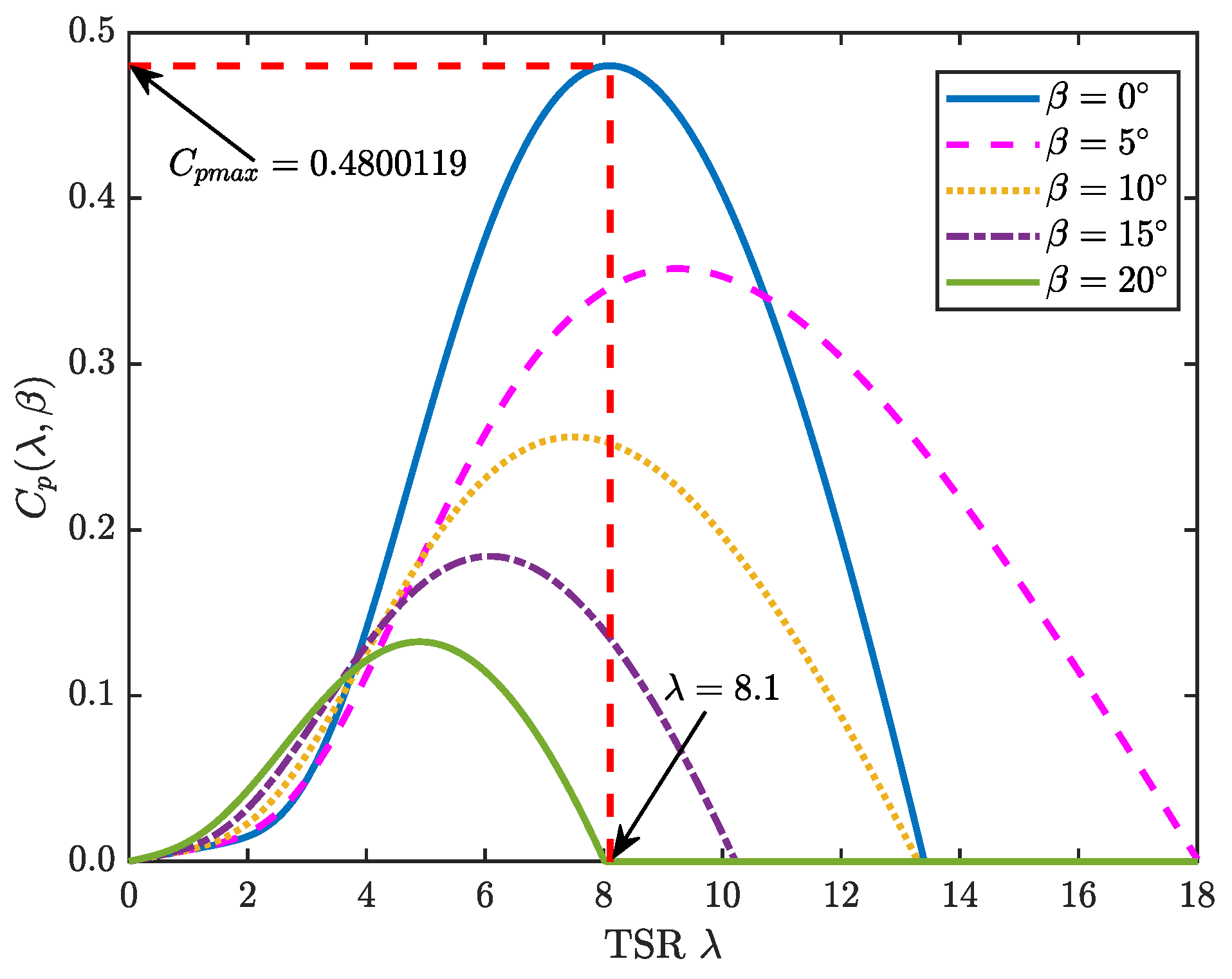
Equations (2)–(4) were used to generate some curves for  C p ( λ , β ) , as depicted in Figure 2. As can be seen,  C p ( λ , β )  reaches its peak when  β = 0 . The corresponding optimal value for the tip-speed ratio is  λ o p t = 8.1 . Note that if we plug this value into the left-hand side of Equation (2), then we can see that the corresponding optimal angular velocity  ω m _ o p t  has to change as time evolves because the wind speed  v w , which is random by its nature, changes continuously.
Furthermore, the mechanical torque can be computed from Equations (1) and (2), i.e.,
T m = P m ω m = π 2 λ ρ r 3 C p ( λ , β ) v w 2 ,
Going deeper into this evaluation, one can show that the corresponding optimal torque is given by (e.g., [5])
T m _ o p t = π ρ r 5 C p m a x 2 λ o p t 3 ω m _ o p t 2 .

2.2. Permanent Magnet Synchronous Generator Connected to Diode Rectifier: Analysis and Modeling

The direct quadrature (d-q) reference frame, also known as a synchronous reference frame (e.g., [41]), is frequently used to represent the PMSG. The current literature suggests that the PMSG dynamics, represented by the d-q reference frame, follow (e.g., [5])
V s d = R s i s d L d d i s d d t + ω e L d i s q , V s q = R s i s q L q d i s q d t + n p ω m L q i s d + ϕ m ,
where the pairs  ( V s d , V s q )  and  ( i s d , i s q )  represent the corresponding voltages and currents, respectively.  R s ω e ϕ m , and  n p  denote the stator resistance, the electrical angular speed, the magnetic flux, and the number of pole pairs, respectively.  L d  and  L q  are the d-q stator inductances.
The terminal phase voltage  V s  is related to d-q stator voltages  V s d  and  V s q  as follows [13,42]:
V s = V s d 2 + V s q 2 .
Neglecting the damping coefficient, the mechanical motion equation is given by [8]
d ω m d t = 1 J ( T m T e m ) ,
where  J > 0  represents the total moment inertia, and  T e m  stands for the electromagnetic torque, which can be expressed by [2]
T e m = 3 2 n p ϕ m i s q + ( L d L q ) i s d i s q
In a surface-mounted PMSG, the permanent magnets are mounted on the surface of the rotor. This configuration results in  L q L q , as referenced in [42]. Thus, the electromagnetic torque expressed in Equation (10) equals
T e m = 3 2 n p ϕ m i s q .
Since the currents  i d c  and  i s q  are related through the expression (e.g., [5])
i d c = π 2 3 i s q ,
we can use Equation (11) to write
T e m = 3 3 π n p ϕ m i d c .
On the other hand, the rectifier DC-side voltage  v d c  can be expressed as [13]
v d c = 3 3 π V s .
According to the authors of [15], under steady-state operation, the voltage  V s  satisfies the following relation:
V s 2 = E 2 ( ω e L s I s ) 2 ,
where the stator current  I s  equals [42]
I s = i s q 2 + i s d 2 .
It is worth mentioning that the machine’s back-electromotive force E is given by (e.g., [13,42])
E = ϕ m ω e ,
Substituting Equation (15) into Equation (14), it can be seen that  v d c  varies almost linearly with respect to  ω m  [14], which is described easily by the following rule:
v d c = α ω m ,
where  α  is a positive constant.

2.3. Modeling of DC-DC Boost Converter with Time-Varying Loads

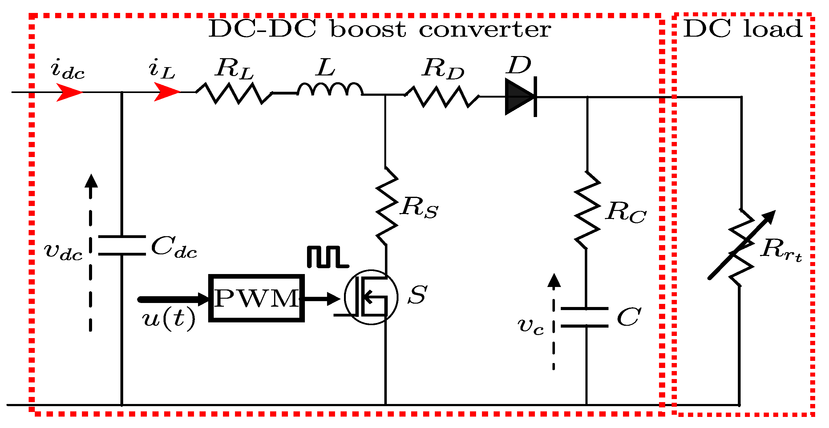
This section reviews the modeling of a specific DC circuit: the DC-DC boost converter (see Figure 3). As described in the literature [43], this converter can be modeled based on the operation of the MOSFET S. When the MOSFET is in the “ON” mode, the dynamics of the DC-DC boost converter can be expressed as follows:
x ˙ ( t ) = 1 C d c i d c ( t ) v d c ( t ) 1 C d c 0 1 L R L + R S L 0 0 0 1 C ( R r t + R C ) A 1 , r t ( x ( t ) ) x ( t ) , t 0 ,
where  x ( t ) = v d c ( t ) , i L ( t ) , v c ( t ) T R 3  is the system state; here,  v d c i L , and  v c  denote the voltage on the input capacitor, the inductor current, and the output capacitor voltage, respectively.
During the “OFF” time of the MOSFET S, the dynamics of the DC-DC boost converter can be represented as follows:
x ˙ ( t ) = 1 C d c i d c ( t ) v d c ( t ) 1 C d c 0 1 L R L + R D + R C R r t R C + R r t L R r t L ( R C + R r t ) 0 R r t C ( R C + R r t ) 1 C ( R r t + R C ) A 2 , r t ( x ( t ) ) x ( t ) , t 0 .
Recall that  u ( t )  represents the PWM signal, and it keeps switching between 0 and 1. As a result, we can apply the time-average approach to Equations (19) and (20) to obtain (e.g., [44])
x ˙ ( t ) = A 1 , r t ( x ( t ) ) x ( t ) u ( t ) + A 2 , r t ( x ( t ) ) x ( t ) 1 u ( t ) = A 2 , r t ( x ( t ) ) x ( t ) + A 1 , r t ( x ( t ) ) A 2 , r t ( x ( t ) ) x ( t ) u ( t ) , t 0 .
Relabeling the terms as  A r t ( x ( t ) ) = A 2 , r t ( x ( t ) )  and
B r t ( x ( t ) ) = A 1 , r t ( x ( t ) ) A 2 , r t ( x ( t ) ) x ( t ) = 0 R S + R D + R C R r t R C + R r t L i L ( t ) + R r t L ( R C + R r t ) v c ( t ) R r t C ( R C + R r t ) i L ( t ) ,
we obtain the nonlinear dynamical system
x ˙ ( t ) = A r t ( x ( t ) ) x ( t ) + B r t ( x ( t ) ) u ( t ) , t 0 , x ( 0 ) = x 0 R n .
It is clear from Equation (22) that the system state  x ( t )  assumes a complicated nonlinear form. This condition is inevitable because the equations from the WECS are inherently nonlinear. Moreover, the control  u ( t )  multiplies  x ( t )  on the right-hand side of Equation (22), imposing additional challenges from the control design viewpoint. To partially overcome such drawbacks, we propose the TS fuzzy approach. This approach follows ideas borrowed from [34]. More details are given in the following.
Furthermore, we review how stochastic modeling can help us cope with the random features that act upon the WECS.

3. Stochastic Load Consumption Using Markov Chain Model

3.1. Motivation: Stochastic Load

The total power consumption in a standalone, off-grid WECS that supplies various loads with different power profiles can exhibit unpredictable behavior due to user activities or the unique characteristics of the appliances in use. For instance, some loads may have intermittent usage patterns or variable power demands over time. Additionally, the way that power is distributed among the loads can influence the stochastic nature of the overall load consumption. If the loads have distinct power profiles, such as one load requiring more power during the daytime and another needing more power at night, the total load consumption will vary throughout the day [39]. Hence, one of the main challenges is that time-varying loads usually exhibit stochastic behavior [45].
Fluctuations in load consumption, which follow a random pattern, can significantly impact the overall stability and reliability of the WECS. These variations present a substantial challenge in designing a controller that efficiently minimizes energy waste and maintains system stability. Achieving optimal performance requires careful and continuous monitoring. Therefore, the WECS should be designed to account for random load consumption. Likewise, a power control strategy needs to be developed to optimize wind energy generation even under random load consumption.
Markov chains are integral to the real-time estimation of random behavior in real systems, providing a robust framework for dynamically predicting future modes based on the present mode. By modeling load variations as modes in a Markov chain, with specific transition probabilities between these modes, the stochastic nature of load demands can be effectively captured and analyzed. This allows the system to anticipate changes in load conditions and adjust its operation accordingly, thus enhancing the overall efficiency and stability of the WECS.
In a real-time context, a Markov chain continuously updates its mode probabilities as new data become available, allowing for immediate adaptation to changing conditions [40,44,46,47,48]. This dynamic updating process is particularly valuable in applications requiring instantaneous decision-making and forecasting, such as WECS systems under unpredictable load consumption.

3.2. Markov Chain-Based System

A continuous-time Markov chain process  { r t , t 0 }  takes values in the finite set  K = { 1 , , k }  and satisfies transition probabilities as follows:
Pr [ r t + Δ = m | r t = n ] = π n m Δ + o ( Δ ) , n m , 1 + π n n Δ + o ( Δ ) , n = m ,
where  Δ > 0  and  lim Δ 0 o ( Δ ) Δ = 0 . The Markov chain is driven by the transition rate matrix  Q = [ π n m ] k × k , where  π n m  stands for the transition rate from mode n at instant t to mode m at  t + Δ , satisfying  π n m 0  for  n m  and  π n n + { m = 1 , m n } k π n m = 0 .
Assumption 1.
The resistive load of the DC-DC boost converter shown in Figure 3 is driven by a Markov chain (i.e., the resistor  R r t  depends on the Markov chain  r t ).
Under Assumption 1, the current  i d c  is related to the DC-side voltage  v d c  as follows [5]:
v d c = ( 1 u ) 2 i d c R r t .
Thus, from Equation (24), the DC power to the load equals
P d c = v d c i d c = ( 1 u ) 2 i d c 2 R r t .
As depicted in Equation (25), variations in  R r t  profoundly influence the stability and performance of the WECS. To mitigate these effects, the duty cycle of the DC-DC boost converter  u ( t )  is adjusted by controlling the rectifier DC voltage  v d c , which, in turn, maximizes the DC rectifier power  P d c , as will be discussed in the next section. A Markov chain model is employed to predict future load modes based on the present mode, providing a probabilistic approach to forecasting load demands. This predictive model integrates with the TS fuzzy control strategy to optimize power extraction and ensure efficient operation, even in the presence of unpredictable load variations.
Algorithm 1 presents a Markov chain-based methodology designed to predict load consumption in a WECS, optimizing the MPPT process under varying random load conditions. Initially, the algorithm initializes a finite set of modes  K , each representing distinct levels of load demand. It begins by setting the initial mode  r 0  and defining a transition rate matrix Q that captures the probabilities of transitioning between different load modes.
The transition probabilities  Pr [ r t + Δ = m | r t = n ]  are defined to predict how likely it is to move from mode n to mode m within a time step  Δ . These probabilities are formulated based on transition rates  π n m , ensuring that the sum of rates departing from any mode n is zero, thereby maintaining consistency.
As the algorithm progresses, it updates the present Markov mode  r t  to predict future load modes. This iterative process allows for continuous adjustments in transition probabilities, accommodating observed and anticipated load consumption modes. The predicted load value derived from this Markov chain prediction is then integrated into the TS fuzzy stochastic MPPT scheme. This iterative approach ensures real-time adjustments to the WECS, maintaining efficient power extraction even under random load consumption.
Algorithm 1 Markov chain-based load prediction for MPPT approach of WECS
1:
   Step 1: Initialization and definition of transition probabilities:
    → Define a finite set  K = { 1 , , k } .
    → Initialize the initial Markov mode  r 0 .
    → Define the transition rate matrix  Q = [ π n m ] k × k .
    → Define the transition probabilities as  Pr [ r t + Δ = m | r t = n ] .
2:
    Step 2: Evolution of load modes with updates:
    → Update the Markov mode  r t  to predict the future load mode based on the present mode.
    → Adjust transition probabilities based on the predicted load consumption.
3:
    Step 3: TS fuzzy stochastic MPPT scheme:
    → Apply the predicted load value to the MPPT block.
4:
    Step 4: Repeat the process:
    → Continuously predict the future load mode and update the probabilities.
Remark 1.
Based on Equations (7), (9) and (12), the subsystem consisting of the wind turbine, PMSG, and diode rectifier can be considered a DC current source, as it provides a DC current  i d c ( t )  to the DC-DC boost converter after rectification. Additionally, the proposed controller relies only on DC measurements (specifically, the current and voltage) to maximize the DC rectifier power by controlling the DC-side voltage. Furthermore, by controlling the DC-side voltage, the rotor speed can be indirectly controlled according to Equation (18). Thus, the mechanical dynamics are not included in the TS fuzzy modeling and controller design. Consequently, only the DC-DC boost converter model (refer to Equation (22)) is used in the TS fuzzy modeling, controller design, and stability analysis, as detailed in the following section.

4. TS Fuzzy Stochastic MPPT Controller

This section presents the MPPT controller-based TS fuzzy approach for a WECS with stochastic loads. Before introducing the control strategy, we recall the TS fuzzy modeling that handles the nonlinearities of the system.

4.1. TS Fuzzy Modeling

The TS fuzzy model is explained by “IF–THEN” rules [33]. Hence, in the next step, the nonlinear model (refer to Equation (22)) is then transformed into a TS fuzzy representation and contains the following premise variables:
z ( t ) = z 1 ( t ) z 2 ( t ) z 3 ( t ) T = i d c ( t ) v d c ( t ) i L ( t ) v c ( t ) T .
Consequently, the TS fuzzy model is examined in the  i th rule as follows:
  • Model rule i: IF  z 1 ( t )  is  ϑ i 1  and … and  z p ( t )  is  ϑ i p , THEN
    x ˙ ( t ) = A i n x ( t ) + B i n u ( t ) , i D = 1 , 2 , . . . , μ ,
    where  ϑ i 1 ϑ i p  are the fuzzy sets,  μ  is the number of fuzzy rules, and p is the number of premise variables.
Therefore, by applying the fuzzy rules in Equation (27), we obtain (e.g., [44])
x ˙ ( t ) = i = 1 μ h i ( z ( t ) ) A i n x ( t ) + B i n u ( t ) , i D = 1 , 2 , . . . , μ , x ( 0 ) = x 0 R n ,
where  A i n  and  B i n  are the system matrices associated with the  i th rule, which are given by
A i n = 1 C d c z i 1 1 C d c 0 1 L R L + R D + R C R n R C + R n L R n L ( R c + R n ) 0 R n C ( R C + R n ) 1 C ( R n + R C ) , B i n = 0 R S + R D + R C R n R C + R n L z i 2 + R n L ( R C + R n ) z i 3 R n C ( R C + R n ) z i 2 ,
and  h i ( z ( t ) ) = q = 1 p ϑ i q ( z q ( t ) ) i = 1 μ q = 1 p ϑ i q ( z q ( t ) )  denotes membership functions that satisfy  0 h i 1  and  i = 1 μ h i ( z ( t ) ) = 1 , t 0 ; here,  ϑ i q ( z q ( t ) )  is the membership grade of  z q ( t ) z q m i n z q m a x  in  ϑ i q , given in the following format:
ϑ q m a x ( z q ( t ) ) = z q ( t ) z q m i n z q m a x z q m i n , ϑ q m i n ( z q ( t ) ) = z q m a x z q ( t ) z q m a x z q m i n .
The membership functions  h i ( z ( t ) )  and the matrices  A i n  and  B i n  for the ith rule can be computed based on various combinations of the premise variables, as outlined in Table 1. This approach enables the handling of nonlinearities by breaking down the nonlinear system behavior into a set of simpler linear models, each corresponding to a particular fuzzy rule.

4.2. Maximum Power Point Search Method

Let us assume for the moment that the wind speed  v w  is below the wind turbine threshold speed, and the wind turbine is operating with a constant pitch angle  β . In this case, as shown in Equations (1)–(3), the mechanical power  P m  becomes a function of the rotor speed  ω m . Thus, the MPP is attained when  P m  satisfies
d P m d ω m = 0 .
Using the chain rule [13], this can be expressed in terms of the DC-side voltage  v d c :
d P m d ω m = d P m d v d c · d v d c d ω m = 0 .
Given that, according to Equation (18),
d v d c d ω m = α 0 ,
we obtain
d P m d v d c = 0 .
Assuming no system losses, as suggested in [3,12], the mechanical power equals the rectifier DC-side power  P m = P d c . Thus, Equation (33) becomes
d P d c d v d c = 0 .
This indicates a unique optimal trajectory  v d c _ o p t  for the rectifier DC-side voltage to harness maximum power. By adjusting  v d c  to follow its optimal  v d c _ o p t ( t ) , the extracted power is maximized. Furthermore, when the MPP is attained, the electromagnetic torque  T e m  equals the optimal turbine torque  T m _ o p t  [13]. Using Equations (6), (13) and (18), the optimal rectifier DC-side voltage is given by [5]
v d c _ o p t ( t ) = κ i d c 1 2 ( t ) ,
where  κ = 3 3 π n p ϕ m α 2 K o p t 1 2 . Thus, the objective is to drive the rectifier DC-side voltage  v d c ( t )  to follow its optimal  v d c _ o p t ( t ) . This is achieved using an integral tracking error, as described in Section 4.3.

4.3. Controller Design

As previously mentioned, the rectifier DC-side voltage  v d c ( t )  must be pushed into  v d c _ o p t ( t )  to achieve the MPPT operation. Hence, the new state space is described as follows:
e I ( t ) = 0 t e ( τ ) d τ = 0 t ( v d c _ o p t ( τ ) v d c ( τ ) ) d τ .
Hence, the tracking error dynamic equation is given below:
e ˙ I ( t ) = e ( t ) = v d c _ o p t ( t ) v d c ( t ) = v d c _ o p t ( t ) C 1 x ( t ) ,
where  C 1 = 1 0 0 .
Combining Equations (28) and (37), the augmented system is expressed in terms of the augmented vector  ξ ( t ) = x ( t ) e I ( t )  as follows:
ξ ˙ ( t ) = i = 1 μ h i ( z ( t ) ) A ˜ i n ξ ( t ) + B ˜ i n u ( t ) + B 0 ξ d ( t ) ,
where
A ˜ i n = A i n O 3 × 1 C 1 0 , B ˜ i n = B i n 0 ,
B 0 = O 3 × 1 O 3 × 1 0 1 , and ξ d ( t ) = 0 v d c _ o p t ( t ) .
Moreover, the TS fuzzy controller  u ( t )  is considered to have the same premise variables  z ( t )  and is examined in the following  j th rule:
  • Model rule j: IF  z 1 ( t )  is  ϑ j 1  and … and  z p ( t )  is  ϑ j p , THEN
    u ( t ) = K j n , 1 K j n , 2 · x ( t ) e I ( t ) T = K j n ξ ( t ) , j D = 1 , 2 , . . . , μ
    where  K j n = K j n , 1 K j n , 2  are controller gains.
Hence, the TS fuzzy PDC control  u ( t )  is given by [34]
u ( t ) = j = 1 μ h j ( z ( t ) ) K j n ξ ( t ) , j D = 1 , 2 , . . . , μ .
Substituting Equation (40) into Equation (38), the closed-loop augmented WECS with the tracking performance is given below:
ξ ˙ ( t ) = i = 1 μ j = 1 μ h i ( z ( t ) ) h j ( z ( t ) ) G i j n ξ ( t ) + B 0 ξ d ( t ) ,
where  G i j n = A ˜ i n + B ˜ i n K j n .
The following notation is adopted for simplification:
i = 1 μ j = 1 μ h i ( z ( t ) ) h j ( z ( t ) ) = i , j = 1 μ h i j ( z ( t ) ) .

4.4. Stability Analysis

In this section, we aim to design a feedback fuzzy controller (refer to Equation (40)) to assure the stochastic stability of the closed-loop WECS (refer to Equation (41)) in terms of  H  tracking performance. We begin by defining the stochastic stability and  H  performance tracking.
Definition 1
([49,50]). The augmented WECS (Equation (41)) is stochastically stable if  ξ d ( t ) = 0  and  ( ξ 0 R n , r 0 K ) , satisfying
E 0 ξ ( t ) 2 d t ( ξ 0 , r 0 ) < .
Definition 2
([50]). Given the controller (Equation (40)), the tracking error can be attenuated for the augmented system (Equation (41)) if the system satisfies Definition 1. In this context, the following index function should be minimized for  ν > 0 :
J = E 0 [ e I T ( t ) e I ( t ) ν 2 ξ d T ( t ) ξ d ( t ) ] d t < 0 ,
and then the augmented WECS is stochastically stable and satisfies the  H  tracking performance level ν.
The designed controller’s main goal is to assure the stochastic stability of the closed-loop WECS and to force the WECS to work at its MPP by determining the controller gains  K j n  using LMIs. To maintain the stochastic stability of Equation (41), consider the Lyapunov function, defined as follows:
V ( ξ ( t ) , n ) = ξ T ( t ) P n ξ ( t ) , where P n = P n T > 0 , n K .
If we define  L  as the infinitesimal operator of the Markov process  { r t , t 0 } , then when  L  is acting on  V ( ξ ( t ) , n )  we have
L V ( ξ ( t ) , n ) = ξ ˙ T ( t ) P n ξ + ξ T ( t ) P n ξ ˙ ( t ) + m = 1 k π n m V ( ξ ( t ) , m ) .
First, we show the stability analysis. When  ξ d ( t ) = 0 L V ( ξ ( t ) , n )  expressed in Equation (45) is given as follows:
L V ( ξ ( t ) , n ) = i , j = 1 μ h i j ( z ( t ) ) ξ T ( t ) G i j n T P n + P n G i j n + m = 1 k π n m P m ξ ( t ) , = i , j = 1 μ h i j ( z ( t ) ) ξ T ( t ) Π i j n ξ ( t ) ,
where
Π i j n = G i j n T P n + P n G i j n + m = 1 k π n m P m .
According to Equation (46), it follows that  Π i j n < 0 , provided that  L V ( ξ ( t ) , n ) < 0 . Therefore, by using Dynkin’s formula for a finite time  T  and a constant  ϵ > 0 , we obtain
E 0 T L V ( ξ ( t ) , r t ) d t ( ξ 0 , r 0 ) = E [ V ( ξ ( T ) , r ( T ) ) ] V ( ξ 0 , r 0 ) < ϵ E 0 T ξ T ( t ) ξ ( t ) d t .
Therefore, if  T , then we have
E 0 ξ ( t ) 2 d t ( ξ 0 , r 0 ) < ϵ 1 V ( ξ 0 , r 0 ) E [ V ( ξ ( ) , r ( ) ) ] ϵ 1 V ( ξ 0 , r 0 ) < .
Consequently, according to Definition 1, the stochastic stability of the closed-loop WECS (refer to Equation (41)) is guaranteed.
Furthermore, the stochastic stability condition in terms of  H  tracking performance under the existence of  ξ d ( t ) 0  is given as follows:
L V ( ξ ( t ) , n ) + e I T ( t ) e I ( t ) ν 2 ξ d T ( t ) ξ d ( t ) < 0 ,
where
e I T ( t ) e I ( t ) ν 2 ξ d T ( t ) ξ d ( t ) = ξ T ( t ) C 0 T C 0 ξ ( t ) ν 2 ξ d T ( t ) ξ d ( t ) , = ξ ˜ T ( t ) C 0 T C 0 0 0 ν 2 I ξ ˜ ( t ) ,
with  C 0 = 0 0 0 1 , and  ξ ˜ ( t ) = ξ ( t ) ξ d ( t ) .
As a result, the value of  L V ( ξ ( t ) , n )  follows when we substitute Equation (41) into Equation (45):
L V ( ξ ( t ) , n ) = i , j = 1 μ h i j ( z ( t ) ) ( G i j n ξ ( t ) + B 0 ξ d ( t ) T P n ξ ( t ) + ξ T ( t ) P n G i j n ξ ( t ) + B 0 ξ d ( t ) + m = 1 k π n m V ( ξ ( t ) , m ) ) ) = i , j = 1 μ h i j ( z ( t ) ) ξ T ( t ) G i j n T P n + P n G i j n + m = 1 k π n m P m ξ ( t ) + i , j = 1 μ h i j ( z ( t ) ) ξ T ( t ) P n B 0 ξ d ( t ) + ξ d T ( t ) B 0 T P n ξ ( t ) .
Thus, the satisfaction of the condition expressed in Equation (49) can be ensured by combining Equations (50) and (51):
i , j = 1 μ h i j ( z ( t ) ) ξ ˜ T ( t ) Θ ¯ i j n ξ ˜ ( t ) < 0 ,
with
Θ ¯ i j n = G i j n T P n + P n G i j n + m = 1 k π n m P m + C 0 T C 0 P n B 0 B 0 T P n ν 2 I ,
which is equivalent to
[ P n G i j n ] T + P n G i j n + m = 1 k π n m P m + C 0 T C 0 P n B 0 B 0 T P n ν 2 I < 0 .
Additionally, we have
J = E 0 [ e I T ( t ) e I ( t ) ν 2 ξ d T ( t ) ξ d ( t ) ] d t E 0 [ e I T ( t ) e I ( t ) ν 2 ξ d T ( t ) ξ d ( t ) + L V ( ξ ( t ) , n ) ] d t = E 0 i , j = 1 μ h i j ( z ( t ) ) ξ ˜ T ( t ) Θ ¯ i j n ξ ˜ ( t ) d t .
It follows from Equation (53) that
J = E 0 [ e I T ( t ) e I ( t ) ν 2 ξ d T ( t ) ξ d ( t ) ] d t < 0 .
Definition 2 and Equation (54) allow us to ensure that the closed-loop WECS is stochastically stable and meets the required  H  tracking criteria, which implies maximum power tracking.
Furthermore, to ensure the stochastic stability of the closed-loop WECS (Equation (41)), we need to determine the gains  K j n  for the duty cycle  u ( t ) . Solving the inequality in Equation (53) is required for this. However, this inequality is nonlinear, because the term  P n G i j n = P n A ˜ i n + B ˜ i n K j n  is nonlinear in  K j n  and  P n . Hence, the inequality in Equation (53) should be converted into an LMI. To this end, we pre- and post-multiply Equation (53) by  X n 0 0 I , with  X n = P n 1 . It follows that
[ G i j n X n ] T + G i j n X n + m = 1 k π n m X n X m 1 X n + X n C 0 T C 0 X n B 0 B 0 T ν 2 I < 0 .
However, Equation (55) is still nonlinear in  m = 1 k π n m X n X m 1 X n . To address this issue, we introduce two key variables,  V n ( X )  and  U n ( X ) , expressed, respectively, as follows:
V n ( X ) = π n 1 X n , . . . , π n n 1 X n , π n n + 1 X n , . . . , π n k X n ,
and
U n ( X ) = d i a g X 1 , . . . , X n 1 , X n + 1 , . . . , X k .
Then,
m = 1 k π n m X n X m 1 X n = π n n X n + V n ( X ) U n 1 ( X ) V n T ( X ) .
Therefore, Equation (55) can be rewritten as follows:
[ G i j n X n ] T + G i j n X n + π n n X n + V n ( X ) U n 1 ( X ) V n T ( X ) + X n C 0 T C 0 X n B 0 B 0 T ν 2 I < 0 .
Finally, by applying Schur’s lemma to Equation (56), we obtain the following LMI:
Ψ i j n V n ( X ) X n C 0 T B 0 U n ( X ) 0 0 I 0 ν 2 I < 0 , n K , ( i , j ) D .
where  Ψ i j n = A ˜ i n X n + B ˜ i n Y j n + A ˜ i n X n + B ˜ i n Y j n T + π n n X n  and  Y j n = K j n X n .
Furthermore, we demonstrate that the suggested controller maintains recursive feasibility even under random load variations.

4.5. Recursive Feasibility

Recursive feasibility is critical for systems with inherent uncertainties and variations, ensuring that control strategies consistently compute feasible inputs at each time step from a feasible initial state. This guarantees that feasible solutions will continue to exist in the future under the same control law, maintaining conditions for stability and performance as the system evolves. For a WECS operating under random load conditions, maintaining recursive feasibility alongside stochastic stability is important. It ensures that control inputs, such as the duty cycle of the DC-DC boost converter, keep the WECS operating within physical limits while adapting to unpredictable load variations, resulting in stable and efficient operation.
The LMI presented in Equation (57) incorporates system dynamics under varying conditions and stochastic load variations. The controller gains  K j n = Y j n X n 1 , obtained by solving the LMI in Equation (57), determine the duty cycle  u ( t )  of the DC-DC boost converter, as given by Equation (40). This maintains the WECS within operational limits, adapting to load variations while ensuring optimal performance. For our fuzzy controller design, recursive feasibility ensures that the LMIs derived for stochastic stability and  H  performance remain feasible over the entire operational horizon. This involves designing control gains  K j n  such that the LMIs hold for all admissible modes and transitions of the Markov chain process  r t , t 0 .
By verifying that LMI solutions are robust to variations in the system over time, we ensure that the closed-loop system remains stochastically stable and consistently achieves the desired  H  tracking performance. This careful design ensures that physical constraints are never violated, preserving the longevity and reliability of WECS components. Thus, despite random variations in the load, the stochastic stability and recursive feasibility of the closed-loop system are ensured.
The effectiveness of the suggested approach is validated through simulations in the next section. These simulations demonstrate that the proposed TS fuzzy stochastic MPPT controller can effectively manage random load variations while ensuring both recursive feasibility and stochastic stability.

5. Simulation Results

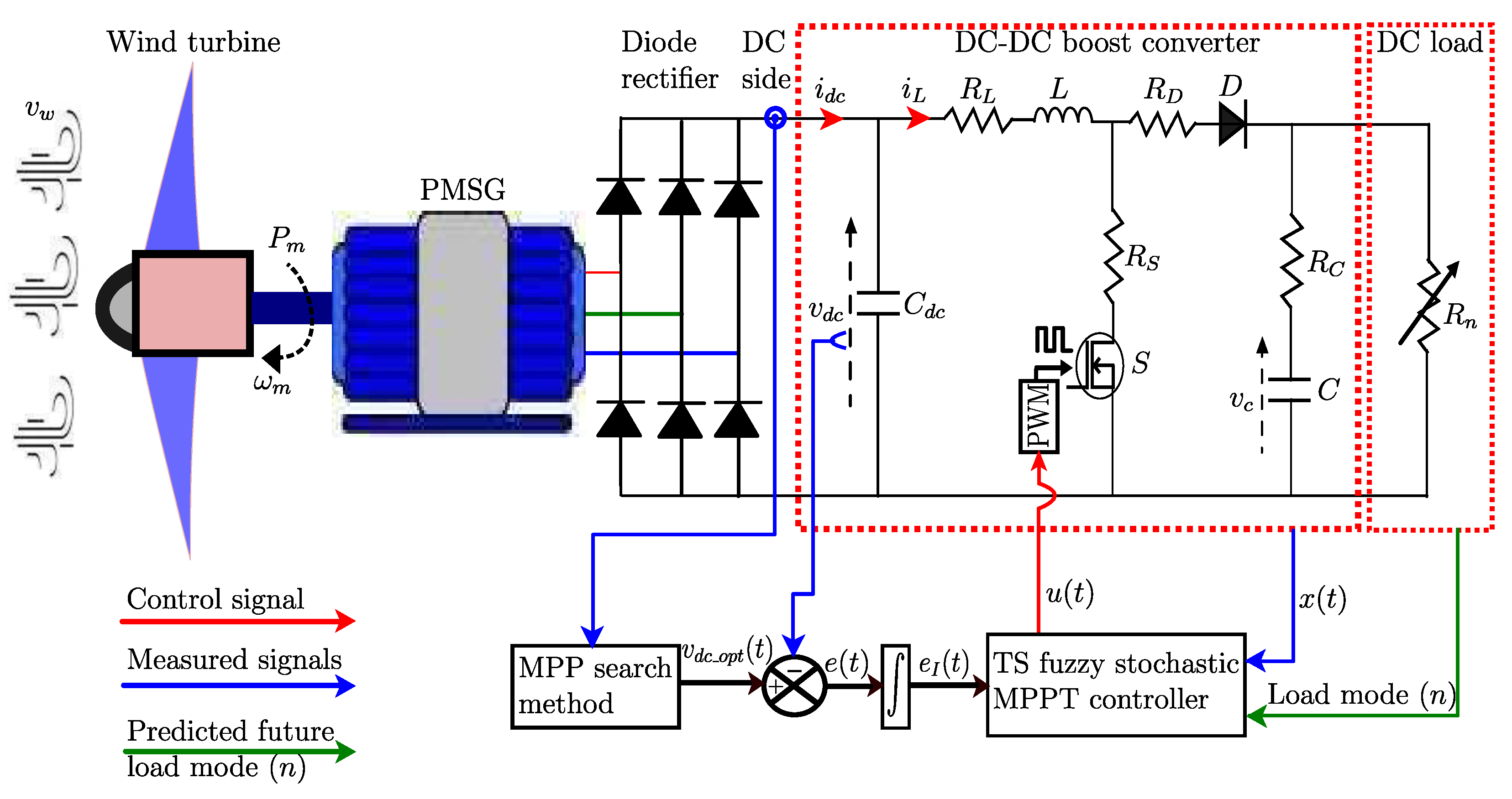
This section assesses the performance and effectiveness of the proposed TS fuzzy stochastic MPPT controller for the WECS in scenarios involving unpredictable load changes and variable wind speed profiles. The analysis explores the specific impact of random loads on control performance. To benchmark its effectiveness, the proposed controller is compared with the classical P&O algorithm. The structure of the controlled WECS configuration with the TS fuzzy stochastic MPPT controller is illustrated in Figure 4. In this configuration, an uncontrolled diode rectifier is used along with a boost converter that controls power extraction by adjusting its duty cycle ( u ( t ) ). MPPT is achieved solely through DC-side variables—specifically, DC voltage ( v d c ) and current ( i d c )—thereby eliminating the need for mechanical sensors. The stochastic MPPT controller efficiently maximizes power capture under fluctuating wind conditions and load variations by regulating the DC-side voltage to follow its optimal ( v d c _ o p t ), thus adjusting the duty cycle. Furthermore, the Markov chain model predicts future load modes (n), allowing the proposed stochastic controller to mitigate the impact of load variations and ensure optimal power extraction even under unpredictable and random load consumption. In addition, the TS fuzzy stochastic MPPT controller block is fully described in Figure 5 with all of its components.
The data for the wind turbine, PMSG, and DC-DC boost converter are provided in Table A1. Additionally, the controller gains, derived from solving the LMI in Equation (57), are presented in Appendix B.

5.1. Impact of Random Load and Wind Speed Variations on Control Performance

The variability in wind speeds and load demands significantly affects WECS performance and stability, making it essential to understand and manage these fluctuations for reliable operation.
The system’s operating conditions related to load variations are represented as a Markov chain with eight modes. The transitions between load modes n and the corresponding load values  R n  are illustrated in Figure 6 and Table 2, respectively. Additionally, the performance of the proposed controller is evaluated under a variable wind speed profile. This profile is simulated as the sum of multiple sinusoidal components to mimic the fluctuating behavior of wind speed, as described in [8,18,36]:
v w ( t ) = 6 + 0.1 sin ( 3.6645 t ) + 0.5 sin ( 1.293 t ) + 1.4 sin ( 0.2665 t ) + 0.1 sin ( 0.1047 t )
The corresponding wind speed profile is depicted in Figure 7.
This evaluation reveals how effectively the suggested controller adapts to changing loads and wind speeds, optimizing WECS performance to track the MPP even under fluctuating conditions.
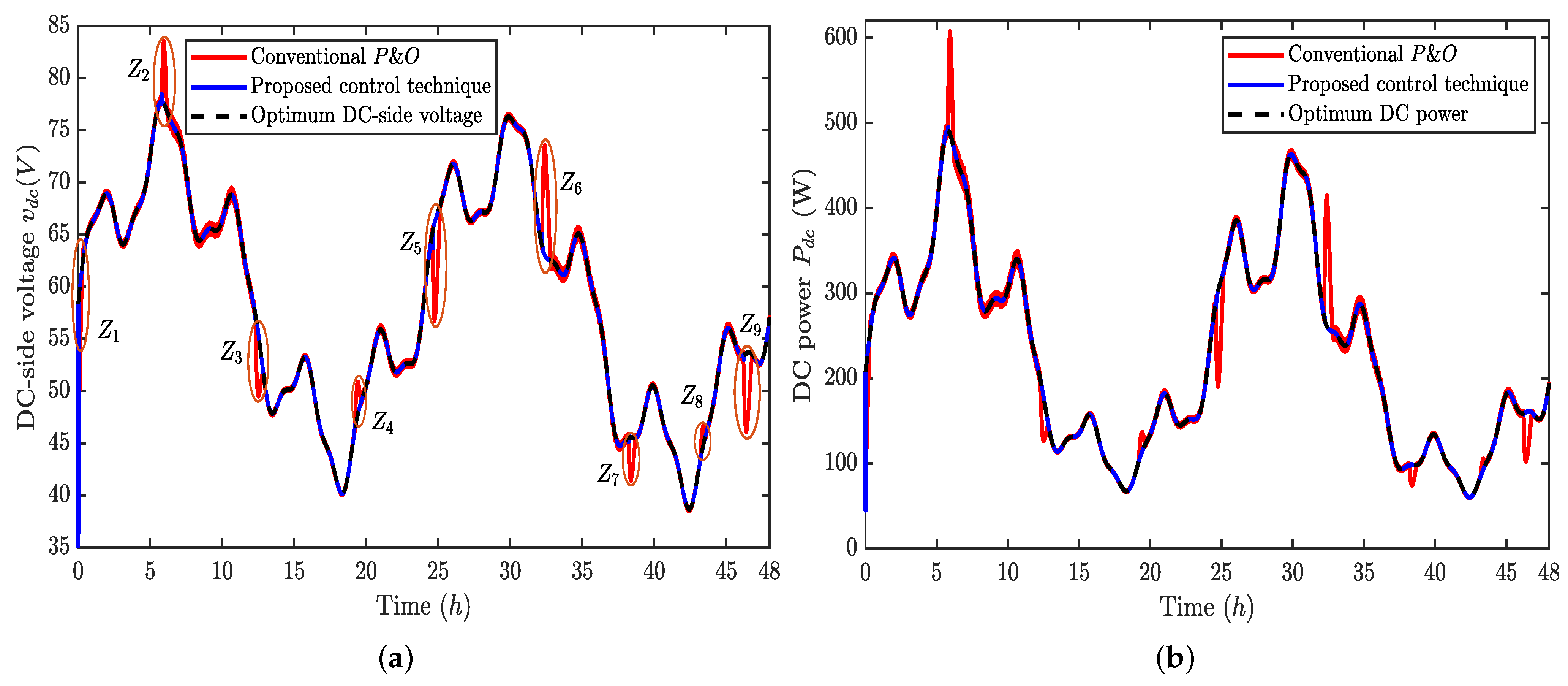
The DC-side voltage and DC power tracking responses of the two MPPT controllers to the wind speed profile (refer to Figure 7) are shown in Figure 8. In Figure 8a, the DC voltage and its optimum are depicted, while in Figure 8b, the DC rectifier power and its optimum are shown. It can be seen that both voltage and power vary with changes in wind speed. Figure 8a demonstrates that both the proposed controller and the P&O algorithm follow the optimal DC-side voltage trajectory  v d c _ o p t ( t ) . However, the P&O algorithm takes longer to reach the MPP with an overshoot, while the proposed approach reaches the MPP more quickly and without an overshoot, as shown in Figure 9. Thus, the suggested approach exhibits a faster response time compared to the traditional method.
Furthermore, the P&O algorithm exhibits a significant transient response when switching to another load operating mode occurs. On the other hand, the proposed controller quickly recovers the voltage to its optimal level when the load changes randomly, which is characterized by an almost unnoticeable transient response, as illustrated in Figure 10.
From the above results, it is confirmed that the suggested controller effectively maintains power tracking with a rapid transient response, particularly in the presence of unpredictable load variations, as shown in Figure 8b. Thus, the proposed controller not only maintains the stochastic stability of the system but also ensures reliable tracking performance under wind speed variations and time-varying random loads.
The zoomed-in portions in Figure 10 underscore the impact of random loads on controller performance. The proposed controller excels by continuously and consistently tracking the optimal DC-side voltage, even during sudden load changes. In contrast, the P&O algorithm takes longer to adapt and exhibits more pronounced transitional behavior, which may yield lower performance. The proposed controller demonstrates significantly improved performance in terms of the settling time, overshoot, and undershoot compared to the P&O algorithm. The settling time, or the duration required for the system to stabilize after a sudden change in load, is significantly shorter with the proposed controller. When the load changes randomly, it rapidly adjusts the DC-side voltage back to its optimal level, minimizing the period during which the system operates below peak efficiency. On the other hand, the P&O algorithm takes longer to settle, indicating a slower response to changing load conditions, which can result in reduced overall efficiency, especially under frequently varying loads. Furthermore, the proposed controller exhibits a significantly lower overshoot and undershoot, preventing excessive deviations from the optimal DC-side voltage and maintaining closer adherence to the desired voltage level. The P&O algorithm, however, shows a higher overshoot and undershoot, leading to more substantial deviations and potential instability during sudden load changes. The proposed controller reduces the overshoot and undershoot so that transitions are smoother and the system stays stable even when the load changes randomly. This shows that it is better at handling the random nature of load demands in a WECS. Moreover, the proposed controller maintains excellent tracking performance without oscillations, ensuring enhanced steady-state operation. It effectively tracks the optimal DC-side voltage, guaranteeing stable MPPT performance despite the randomness of load variations and wind speeds. This stability is essential for the longevity and reliability of WECS components, as continuous oscillations can lead to an increased risk of potential failures.
Furthermore, Figure 11 illustrates the dynamics of the duty cycle  u ( t )  of the DC-DC boost converter in the WECS, showcasing the controller’s ability to respond to unpredictable load fluctuations and wind speed variations. The proposed TS fuzzy stochastic MPPT controller continuously adjusts the duty cycle in real time, maintaining optimal performance even with unexpected changes in wind speed and load conditions. This swift and reliable adjustment ensures that the WECS operates close to its MPP, demonstrating the controller’s robustness and adaptability. The smooth variations in the duty cycle highlight the effectiveness of the proposed control technique in achieving efficient and reliable WECS operation, leading to optimal performance and increased efficiency.

5.2. Tracking Efficiency

The average MPPT efficiency  η M P P T  is computed using the following relation:
η M P P T = 0 t f P d c d t 0 t f P d c _ o p t d t × 100 % ,
where  t f  is the final time,  P d c  is the actual DC power extracted by the MPPT controller, and  P d c _ o p t  is the theoretical optimal DC power available from the wind. Table 3 provides the average MPPT efficiency for the two controllers. The table clearly illustrates that the proposed controller is more efficient than the conventional P&O algorithm. This notable result is achieved due to the proposed algorithm’s enhanced capability to manage fluctuations in wind speed and random load variations. The improved handling of wind speed fluctuations and random load variations by the proposed controller, as previously demonstrated in Figure 8, Figure 9 and Figure 10, shows its superior performance.

5.3. Performance Indices

To comprehensively evaluate the superiority of the proposed MPPT controller over the conventional P&O MPPT algorithm, various performance indices are employed, including the Integral Absolute Error (IAE), Integral Squared Error (ISE), and Integral Time Absolute Error (ITAE) for the DC-side voltage. These indices are calculated as follows [11]:
I A E v d c = 0 t f | e ( τ ) | d τ , I S E v d c = 0 t f | e ( τ ) | 2 d τ , I T A E v d c = 0 t f t | e ( τ ) | d τ .
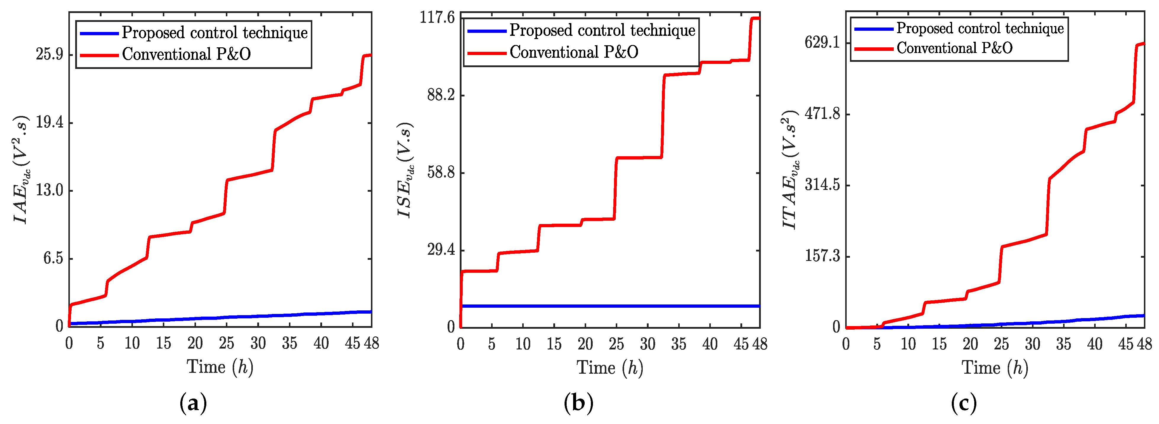
Figure 12 illustrates the temporal evolution of these errors for both the proposed controller and the P&O algorithm. As time progresses, errors generally increase, reflecting the deviation from optimal performance. As can be seen, during load variations, the P&O algorithm exhibits significant spikes in errors, indicative of its less stable performance, as visually confirmed in Figure 10. Conversely, the proposed MPPT controller consistently demonstrates the lowest errors across all metrics—IAE, ISE, and ITAE. The lower IAE indicates reduced deviation from optimal performance, while the decreased ISE shows better precision near the MPP. Additionally, the reduced ITAE highlights the controller’s efficiency in adapting to changes, ensuring consistent MPPT despite fluctuating wind speeds and load variations.
The analysis of these performance indices is further illustrated using box-plots, as shown in Figure 13. Box-plots provide a comparative view of the error metrics for both control methods, showing how the proposed technique maintains stability and reduces errors more effectively under stochastic conditions.

6. Conclusions

This study demonstrates an enhanced approach to improve the efficiency of a WECS under random load demands. By integrating a TS fuzzy model with a stochastic controller, we have optimized the operation of a small-scale autonomous WECS operating under unpredictable load consumption, enabling the rectifier DC-side voltage to be regulated at its optimal level without the need for mechanical sensors. This, in turn, allows the DC-DC boost converter to operate at maximum efficiency, ensuring the maximum possible extraction of electrical energy from a small-scale standalone WECS.
To address the inherent nonlinearity of the WECS, the system was decomposed into linked linear subsystems, connected through a nonlinear membership function within the TS fuzzy model. The load was effectively modeled using a Markov chain process, which predicts future load variations, allowing the controller to quickly adjust to these changes. The control strategy was derived from the LMI solution, which ensures stochastic stability and recursive feasibility, regardless of the random variations in the system.
Simulation results validate the efficacy of the proposed controller under a variable wind speed profile and random load variations. The proposed approach outperforms the conventional P&O algorithm in terms of energy extraction and efficiency. Additional advantages include reduced steady-state oscillations, minimized performance index errors, and a faster response to changes in wind speeds and load variations.
These findings confirm the potential of the proposed stochastic control approach for real-time WECS applications, particularly in small-scale wind energy systems. The approach offers a sensorless solution that maximizes energy capture while ensuring robust performance under fluctuating environmental and load conditions. As such, it is a promising strategy for optimizing standalone WECSs, especially in remote or off-grid settings.

Author Contributions

Conceptualization, A.T. and M.A.; methodology, A.T.; software, A.T. and M.A.; validation, A.T., M.A., F.E.G., H.B. and A.N.V.; formal analysis, A.T.; investigation, A.T.; resources, A.T. and M.A.; writing—original draft preparation, A.T.; writing—review and editing, A.N.V. and G.N.; visualization, A.T.; supervision, F.E.G., H.B. and A.N.V. All authors have read and agreed to the published version of the manuscript.

Funding

This research received no external funding.

Data Availability Statement

Data are contained within the article.

Conflicts of Interest

The authors declare no conflicts of interest.

Abbreviations

The following abbreviations are used in this manuscript:
WECS    Wind energy conversion system
PMSG    Permanent magnet synchronous generator
DC    Direct current
MPPT    Maximum power point tracking
MPP    Maximum power point
IPCs    Indirect power controllers
DPCs    Direct power controllers
TSR    Tip-speed ratio
OTC    Optimal torque control
PSF    Power signal feedback
P&O    Perturb and     observe
INC    Incremental conductance
ORB    Optimum-relation-based
PSO    Particle swarm optimization
ISMC    Integral sliding-mode control
FTSMCFast terminal sliding-mode control
DITSMCdiscrete integral terminal sliding-mode control
TSTakagi–Sugeno
LMILinear matrix inequality
PDCParallel distributed compensation
IAEIntegral Absolute Error
ISEIntegral Squared Error
ITAEIntegral Time Absolute Error

Appendix A

Table A1. Wind turbine, PMSG, and DC-DC boost converter parameters.
Wind Turbine ParametersPMSG ParametersDC-DC Boost Converter Parameters
ρ = 1.225  [Kg/m3] R s = 1.6 [ Ω ] ( L , R L ) = ( 10  [mH], 0.01  [ Ω ] )
r = 1.02  [m] L s = 0.006365  [H] C d c = 470 [ μ F]
λ o p t = 8.1 ϕ m = 0.1852  [Wb] ( C , R C ) = ( 2200 [ μ F], 0.478 [ Ω ] )
C p m a x = 0.4800119 n p = 4 R S = 0.0078 [ Ω ]
J = 18.54 × 10 5  [Kgm2] R D = 0.24 [ Ω ]

Appendix B

The LMI in Equation (57) was solved with  ν = 0.0075  and the probability rate matrix Q using MATLAB (R2021a) with the Mosek optimization solver, leading to the following gains:
K j 1 = [ 0.1199 0.2832 0.0135 22.8867 ] , K j 2 = [ 0.1166 0.2710 0.0135 22.1876 ] , K j 3 = [ 0.1197 0.2827 0.0133 22.8237 ] , K j 4 = [ 0.1209 0.2851 0.0132 23.0541 ] , K j 5 = [ 0.1219 0.2922 0.0129 23.3410 ] , K j 6 = [ 0.1189 0.2793 0.0133 22.6759 ] , K j 7 = [ 0.1228 0.2964 0.0128 23.5544 ] , K j 8 = [ 0.1213 0.2886 0.0130 23.2095 ] ,
Q = 76 8 18 15 5 21 6 3 11 94 24 5 13 9 12 20 9 15 92 5 20 13 26 4 3 8 12 89 11 6 16 33 4 6 19 15 85 7 20 14 12 9 10 5 13 92 25 18 19 3 11 20 7 15 88 13 17 15 8 11 24 7 20 102 .

References

  1. Savino, M.M.; Manzini, R.; Della Selva, V.; Accorsi, R. A new model for environmental and economic evaluation of renewable energy systems: The case of wind turbines. Appl. Energy 2017, 189, 739–752. [Google Scholar] [CrossRef]
  2. Tripathi, S.M.; Tiwari, A.N.; Singh, D. Grid-integrated permanent magnet synchronous generator based wind energy conversion systems: A technology review. Renew. Sustain. Energy Rev. 2015, 51, 1288–1305. [Google Scholar] [CrossRef]
  3. Mendi, B.; Pattnaik, M.; Srungavarapu, G. A single current sensor based adaptive step size MPPT control of a small scale variable speed wind energy conversion system. Appl. Energy 2024, 357, 122492. [Google Scholar] [CrossRef]
  4. Barzegar-Kalashani, M.; Seyedmahmoudian, M.; Mekhilef, S.; Stojcevski, A.; Horan, B. Small-scale wind turbine control in high-speed wind conditions: A review. Sustain. Energy Technol. Assess. 2023, 60, 103577. [Google Scholar] [CrossRef]
  5. Daili, Y.; Gaubert, J.P.; Rahmani, L.; Harrag, A. Quantitative Feedback Theory design of robust MPPT controller for Small Wind Energy Conversion Systems: Design, analysis and experimental Study. Sustain. Energy Technol. Assess. 2019, 35, 308–320. [Google Scholar] [CrossRef]
  6. Boudjemai, H.; Ardjoun, S.A.E.M.; Chafouk, H.; Denai, M.; Elbarbary, Z.M.S.; Omar, A.I.; Mahmoud, M.M. Application of a Novel Synergetic Control for Optimal Power Extraction of a Small-Scale Wind Generation System with Variable Loads and Wind Speeds. Symmetry 2023, 15, 369. [Google Scholar] [CrossRef]
  7. Urtasun, A.; Sanchis, P.; San Martín, I.; López, J.; Marroyo, L. Modeling of small wind turbines based on PMSG with diode bridge for sensorless maximum power tracking. Renew. Energy 2013, 55, 138–149. [Google Scholar] [CrossRef]
  8. Daili, Y.; Gaubert, J.P.; Rahmani, L. Implementation of a new maximum power point tracking control strategy for small wind energy conversion systems without mechanical sensors. Energy Convers. Manag. 2015, 97, 298–306. [Google Scholar] [CrossRef]
  9. Ajami, A.; Alizadeh, R.; Elmi, M. Design and control of a grid tied 6-switch converter for two independent low power wind energy resources based on PMSGs with MPPT capability. Renew. Energy 2016, 87, 532–543. [Google Scholar] [CrossRef]
  10. Martínez-Nolasco, J.; Sámano-Ortega, V.; Botello-Álvarez, J.; Padilla-Medina, J.; Martínez-Nolasco, C.; Bravo-Sánchez, M. Development of a Hardware-in-the-Loop Platform for the Validation of a Small-Scale Wind System Control Strategy. Energies 2023, 16, 7813. [Google Scholar] [CrossRef]
  11. Dursun, E.H.; Kulaksiz, A.A. Second-order sliding mode voltage-regulator for improving MPPT efficiency of PMSG-based WECS. Int. J. Electr. Power Energy Syst. 2020, 121, 106149. [Google Scholar] [CrossRef]
  12. Gouabi, H.; Hazzab, A.; Habbab, M.; Rezkallah, M.; Chandra, A.; Ibrahim, H. Fuzzy adaptive dP-perturb and observe maximum power point tracking controller for wind energy conversion systems: Design and real-time implementation. Sustain. Energy Grids Netw. 2023, 36, 101230. [Google Scholar] [CrossRef]
  13. Dalala, Z.M.; Zahid, Z.U.; Yu, W.; Cho, Y.; Lai, J.S. Design and Analysis of an MPPT Technique for Small-Scale Wind Energy Conversion Systems. IEEE Trans. Energy Convers. 2013, 28, 756–767. [Google Scholar] [CrossRef]
  14. Chen, J.; Lin, T.; Wen, C.; Song, Y. Design of a Unified Power Controller for Variable-Speed Fixed-Pitch Wind Energy Conversion System. IEEE Trans. Ind. Electron. 2016, 63, 4899–4908. [Google Scholar] [CrossRef]
  15. Kumar, R.; Agrawal, H.P.; Shah, A.; Bansal, H.O. Maximum power point tracking in wind energy conversion system using radial basis function based neural network control strategy. Sustain. Energy Technol. Assessments 2019, 36, 100533. [Google Scholar] [CrossRef]
  16. Kumar, D.; Chatterjee, K. A review of conventional and advanced MPPT algorithms for wind energy systems. Renew. Sustain. Energy Rev. 2016, 55, 957–970. [Google Scholar] [CrossRef]
  17. Mousa, H.H.; Youssef, A.R.; Mohamed, E.E. State of the art perturb and observe MPPT algorithms based wind energy conversion systems: A technology review. Int. J. Electr. Power Energy Syst. 2021, 126, 106598. [Google Scholar] [CrossRef]
  18. Nasiri, M.; Milimonfared, J.; Fathi, S. Modeling, analysis and comparison of TSR and OTC methods for MPPT and power smoothing in permanent magnet synchronous generator-based wind turbines. Energy Convers. Manag. 2014, 86, 892–900. [Google Scholar] [CrossRef]
  19. Pagnini, L.C.; Burlando, M.; Repetto, M.P. Experimental power curve of small-size wind turbines in turbulent urban environment. Appl. Energy 2015, 154, 112–121. [Google Scholar] [CrossRef]
  20. Pande, J.; Nasikkar, P.; Kotecha, K.; Varadarajan, V. A Review of Maximum Power Point Tracking Algorithms for Wind Energy Conversion Systems. J. Mar. Sci. Eng. 2021, 9, 1187. [Google Scholar] [CrossRef]
  21. Balbino, A.J.; Nora, B.d.S.; Lazzarin, T.B. An Improved Mechanical Sensorless Maximum Power Point Tracking Method for Permanent-Magnet Synchronous Generator-Based Small Wind Turbines Systems. IEEE Trans. Ind. Electron. 2022, 69, 4765–4775. [Google Scholar] [CrossRef]
  22. Zhang, H.B.; Fletcher, J.; Greeves, N.; Finney, S.; Williams, B. One-power-point operation for variable speed wind/tidal stream turbines with synchronous generators. IET Renew. Power Gener. 2011, 5, 99–108. [Google Scholar] [CrossRef]
  23. Kesraoui, M.; Korichi, N.; Belkadi, A. Maximum power point tracker of wind energy conversion system. Renew. Energy 2011, 36, 2655–2662. [Google Scholar] [CrossRef]
  24. Xia, Y.; Ahmed, K.H.; Williams, B.W. Wind Turbine Power Coefficient Analysis of a New Maximum Power Point Tracking Technique. IEEE Trans. Ind. Electron. 2012, 60, 1122–1132. [Google Scholar] [CrossRef]
  25. Abdullah, M.A.; Al-Hadhrami, T.; Tan, C.W.; Yatim, A.H. Towards Green Energy for Smart Cities: Particle Swarm Optimization Based MPPT Approach. IEEE Access 2018, 6, 58427–58438. [Google Scholar] [CrossRef]
  26. Şerban, I.; Marinescu, C. A sensorless control method for variable-speed small wind turbines. Renew. Energy 2012, 43, 256–266. [Google Scholar] [CrossRef]
  27. Fathabadi, H. Novel high efficient speed sensorless controller for maximum power extraction from wind energy conversion systems. Energy Convers. Manag. 2016, 123, 392–401. [Google Scholar] [CrossRef]
  28. Dursun, E.H.; Koyuncu, H.; Kulaksiz, A.A. A novel unified maximum power extraction framework for PMSG based WECS using chaotic particle swarm optimization derivatives. Eng. Sci. Technol. Int. J. 2021, 24, 158–170. [Google Scholar] [CrossRef]
  29. Yin, X.X.; Lin, Y.G.; Li, W.; Gu, Y.J.; Lei, P.F.; Liu, H.W. Sliding mode voltage control strategy for capturing maximum wind energy based on fuzzy logic control. Int. J. Electr. Power Energy Syst. 2015, 70, 45–51. [Google Scholar] [CrossRef]
  30. Yin, X.X.; Lin, Y.G.; Li, W.; Gu, Y.J.; Liu, H.W.; Lei, P.F. A novel fuzzy integral sliding mode current control strategy for maximizing wind power extraction and eliminating voltage harmonics. Energy 2015, 85, 677–686. [Google Scholar] [CrossRef]
  31. Yazıcı, İ.; Yaylacı, E.K. Discrete-time integral terminal sliding mode based maximum power point controller for the PMSG-based wind energy system. IET Power Electron. 2019, 12, 3688–3696. [Google Scholar] [CrossRef]
  32. Luo, Z.; Li, X.; Jiang, C.; Li, Z.; Long, T. Permeability-Adjustable Nanocrystalline Flake Ribbon in Customized High-Frequency Magnetic Components. IEEE Trans. Power Electron. 2024, 39, 3477–3485. [Google Scholar] [CrossRef]
  33. Tanaka, K.; Wang, H.O. Takagi-Sugeno Fuzzy Model and Parallel Distributed Compensation. In Fuzzy Control Systems Design and Analysis; John Wiley & Sons, Ltd.: Hoboken, NJ, USA, 2001; Chapter 2; pp. 5–48. [Google Scholar] [CrossRef]
  34. Nguyen, A.T.; Taniguchi, T.; Eciolaza, L.; Campos, V.; Palhares, R.; Sugeno, M. Fuzzy Control Systems: Past, Present and Future. IEEE Comput. Intell. Mag. 2019, 14, 56–68. [Google Scholar] [CrossRef]
  35. López-Flores, D.R.; Márquez-Gutierrez, P.R.; Baray-Arana, R.E.; Ramirez-Alonso, G. Efficient and Fast Wind Turbine MPPT Algorithm Using TS Fuzzy Logic and Optimal Relation Methods. IEEE Lat. Am. Trans. 2024, 22, 612–619. [Google Scholar] [CrossRef]
  36. Kharrat, M.; Abderrahim, S.; Allouche, M. Robust H2-Optimal TS Fuzzy Controller Design for a Wind Energy Conversion System. Adv. Mater. Sci. Eng. 2022, 2022, 5428109. [Google Scholar] [CrossRef]
  37. Liu, P.; Yang, W.T.; Yang, C.E.; Hsu, C.L. Sensorless wind energy conversion system maximum power point tracking using Takagi–Sugeno fuzzy cerebellar model articulation control. Appl. Soft Comput. 2015, 29, 450–460. [Google Scholar] [CrossRef]
  38. Abderrahim, S.; Allouche, M.; Chaabane, M. Intelligent power control of wind conversion system based on Takagi–Sugeno fuzzy model. Int. J. Circuit Theory Appl. 2023, 51, 2247–2265. [Google Scholar] [CrossRef]
  39. Iqteit, N.A.; Arsoy, A.B.; Çakır, B. The random varying loads and their impacts on the performance of smart grids. Electr. Power Syst. Res. 2022, 209, 107960. [Google Scholar] [CrossRef]
  40. Aatabe, M.; Abbadi, R.E.; Vargas, A.N.; Bouzid, A.E.M.; Bawayan, H.; Mosaad, M.I. Stochastic Energy Management Strategy for Autonomous PV–Microgrid Under Unpredictable Load Consumption. IEEE Access 2024, 12, 84401–84419. [Google Scholar] [CrossRef]
  41. Ramezani, M.; Li, S.; Sun, Y. DQ-reference-frame based impedance and power control design of islanded parallel voltage source converters for integration of distributed energy resources. Electr. Power Syst. Res. 2019, 168, 67–80. [Google Scholar] [CrossRef]
  42. Paul, S.; Chang, J. Model-based design of variable speed non-salient pole permanent magnet synchronous generator for urban water pipeline energy harvester. Int. J. Electr. Power Energy Syst. 2021, 125, 106402. [Google Scholar] [CrossRef]
  43. Siddhartha, V.; Hote, Y.V. Systematic circuit design and analysis of a non-ideal DC–DC pulse width modulation boost converter. IET Circuits Devices Syst. 2018, 12, 144–156. [Google Scholar] [CrossRef]
  44. Aatabe, M.; El Guezar, F.; Vargas, A.N.; Bouzahir, H. A novel stochastic maximum power point tracking control for off-grid standalone photovoltaic systems with unpredictable load demand. Energy 2021, 235, 121272. [Google Scholar] [CrossRef]
  45. Giaouris, D.; Papadopoulos, A.I.; Patsios, C.; Walker, S.; Ziogou, C.; Taylor, P.; Voutetakis, S.; Papadopoulou, S.; Seferlis, P. A systems approach for management of microgrids considering multiple energy carriers, stochastic loads, forecasting and demand side response. Appl. Energy 2018, 226, 546–559. [Google Scholar] [CrossRef]
  46. Zhai, S.; Sun, Y.; Cui, H.; Hu, Y.; Li, Z. Adjustable loads control and stochastic stability analysis for multi-energy generation system based on Markov model. Neural Comput. Appl. 2020, 32, 1517–1529. [Google Scholar] [CrossRef]
  47. Aatabe, M.; El Guezar, F.; Bouzahir, H.; Vargas, A.N. Constrained stochastic control of positive Takagi-Sugeno fuzzy systems with Markov jumps and its application to a DC-DC boost converter. Trans. Inst. Meas. Control 2020, 42, 3234–3242. [Google Scholar] [CrossRef]
  48. Vargas, A.N.; Sampaio, L.P.; Acho, L.; Zhang, L.; do Val, J.B.R. Optimal Control of DC-DC Buck Converter via Linear Systems With Inaccessible Markovian Jumping Modes. IEEE Trans. Control Syst. Technol. 2016, 24, 1820–1827. [Google Scholar] [CrossRef]
  49. Costa, O.L.; Fragoso, M.D.; Todorov, M.G. Continuous-Time Markov Jump Linear Systems; Probability and Its Applications; Springer: Berlin/Heidelberg, Germany, 2013. [Google Scholar] [CrossRef]
  50. Cui, D.; Wang, Y.; Su, H.; Xu, Z.; Que, H. Fuzzy-model-based tracking control of Markov jump nonlinear systems with incomplete mode information. J. Frankl. Inst. 2021, 358, 3633–3650. [Google Scholar] [CrossRef]
Figure 1. Wind energy conversion system configuration.
Energies 17 04927 g001
Figure 2. Curves illustrating the function  C p ( λ , β ) .
Energies 17 04927 g002
Figure 3. DC-DC boost converter representation.
Energies 17 04927 g003
Figure 4. Building blocks of the controlled WECS.
Energies 17 04927 g004
Figure 5. Internal structure of the proposed controller.
Energies 17 04927 g005
Figure 6. Unpredictable load modes driven by Markov chain.
Energies 17 04927 g006
Figure 7. Wind speed profile.
Energies 17 04927 g007
Figure 8. DC rectifier voltage and power responses: (a) DC-side voltage, (b) DC rectifier power.
Energies 17 04927 g008
Figure 9. Zoom  Z 1  of Figure 8a: response time at start-up.
Energies 17 04927 g009
Figure 10. Zoomed-in parts of Figure 8a: Zoom  Z 2  to Zoom  Z 9 .
Energies 17 04927 g010
Figure 11. Duty cycle of the DC-DC boost converter.
Energies 17 04927 g011
Figure 12. Comparison of performance indices: (a) IAE, (b) ISE, (c) ITAE.
Energies 17 04927 g012
Figure 13. Box-plots of performance indices: (a) IAE, (b) ISE, (c) ITAE.
Energies 17 04927 g013
Table 1. Fuzzy rules.
ith RuleMembership GradeValue of  z iq
ϑ i 1 ϑ i 2 ϑ i 3 z i 1 z i 2 z i 3
1 ϑ 1 m i n ϑ 2 m i n ϑ 3 m i n z 1 m i n z 2 m i n z 3 m i n
2 ϑ 1 m i n ϑ 2 m i n ϑ 3 m a x z 1 m i n z 2 m i n z 3 m a x
3 ϑ 1 m i n ϑ 2 m a x ϑ 3 m i n z 1 m i n z 2 m a x z 3 m i n
4 ϑ 1 m i n ϑ 2 m a x ϑ 3 m a x z 1 m i n z 2 m a x z 3 m a x
5 ϑ 1 m a x ϑ 2 m i n ϑ 3 m i n z 1 m a x z 2 m i n z 3 m i n
6 ϑ 1 m a x ϑ 2 m i n ϑ 3 m a x z 1 m a x z 2 m i n z 3 m a x
7 ϑ 1 m a x ϑ 2 m a x ϑ 3 m i n z 1 m a x z 2 m a x z 3 m i n
8 ϑ 1 m a x ϑ 2 m a x ϑ 3 m a x z 1 m a x z 2 m a x z 3 m a x
Table 2. Values of the load resistor.
Modes n = 1 n = 2 n = 3 n = 4 n = 5 n = 6 n = 7 n = 8
R n ( Ω ) 3527303862335055
Table 3. MPPT efficiency.
ControllerProposedConventional P&O
Average MPPT efficiency99.93%97.60%
Disclaimer/Publisher’s Note: The statements, opinions and data contained in all publications are solely those of the individual author(s) and contributor(s) and not of MDPI and/or the editor(s). MDPI and/or the editor(s) disclaim responsibility for any injury to people or property resulting from any ideas, methods, instructions or products referred to in the content.