Abstract
When microgrids operate autonomously, they must curtail the surplus of renewable energy sources (RES) while minimising reliance on gas. However, when interconnected, microgrids can collaboratively minimise RES curtailment and gas consumption due to the ability of exchanging power. This paper presents a centralised controller and energy management of multiple standalone AC microgrids interconnected to a common AC bus using back-to-back converters. Each microgrid consists of RES, a battery, a gas-powered auxiliary unit, and a load. The battery’s state of charge (SOC) is controlled and is used in the AC bus frequency to indicate whether the microgrid has a surplus or shortage of power. High-level global droop control exchanges power between the microgrids. The optimisation problem for this interconnected system is modelled cooperatively to determine the optimal dispatch solution that minimises the energy cost from the auxiliary unit. The optimal dispatch is solved in three cases using the Nelder–Mead simplex algorithm under different settings: one-variable optimisation, three-variable optimisation with the standard droop equation, and three-variable optimisation with a modified droop equation. The optimised performance results are compared with those of the non-optimised benchmark to determine the percentage of optimal performance. The simulation results show that the total energy cost from the auxiliary unit is minimised by 8.98%.
1. Introduction
Microgrids provide a flexible architecture for the integration of RES to meet the growing load demand. They provide both grid and off-grid solutions and help in the widespread use of low-carbon energy sources in developed and developing countries. The voltage and frequency are strengthened by the grid in grid-connected mode when compared to its off-grid counterpart, which relies on its internal backup system, like the BESS and auxiliary power, without any external support. Standalone microgrids provide significant environmental, technical, and economic benefits, which include the use of the abundant region-specific RES to build a sustainable future; reductions in the cost of the investment infrastructure that would have been invested in transmission lines, gas lines etc.; an increased supply duration as the resources are local to the point of use; lower costs in the operational and design stages; reliability; and the avoidance of market monopoly due to the diversified energy mix [1,2].
Standalone microgrids are challenged by their limited capacity to contain as many RES as possible to meet greater load demands [3]. They curtail more surplus power from the RES when the BESS is fully charged and the available power from the RES is higher than the load requires. Hence, single microgrids are limited by the choice to curtail more RES when there is a surplus and shed more load when there is an insufficient supply from the RES. Moreover, when singly operated, standalone microgrids are integrated with diesel or gas generators as backup systems, hence use fossil fuel to meet the load demand [2]. Therefore, standalone microgrids in different geographical locations/regions are interconnected to overcome the limitations of singly operated, standalone microgrids and provide enhanced flexibility for better RES utilisation and supply availability. Furthermore, with the ongoing increase in the deployment of RES from wind and solar PV in microgrids, the future will be challenged by a surplus of remote microgrids in close proximity.
Interconnected microgrids consist of multiple (two or more) standalone microgrids that are geographically isolated and interconnected via different architectures for improved flexibility. Multiple interconnected microgrids accommodate more RES and utilise their reserve capacities to meet the demands of local and global loads while operating independently and cooperatively. Interconnected microgrids provide higher potential to enhance the network’s dependability, adaptability, durability, and sustainability. Interconnected microgrids exhibit a high self-healing capacity. During faults or outages that cause isolation to any part of the microgrid, the network can safely continue operation by sharing its reserve capacities with other microgrids connected to the network to achieve overall reliability and minimise load shedding [4]. The structure of the interconnection architecture is vital to enhance the performance of the respective microgrids under dynamic conditions and helps to provide mutual support. It is worth noting that the microgrid interconnection architecture varies depending on the support that the microgrid needs or delivers. Therefore, interconnected microgrids may not have a static interconnection architecture; instead, the interconnection structure and control strategy can change due to the connection/disconnection of the microgrid or other neighbouring utility grids. Microgrids can be interconnected in two major architectures, either as a common AC or DC bus, and a comparison of these and their benefits is provided in [2,3]. Due to this, various research efforts have been undertaken to solve the electricity problem in sub-Saharan Africa using the common AC bus, which is highly preferred because it is a cost-efficient technology, easy to implement, and allows ease of integration with existing AC links and other power system infrastructures in the region, as detailed in [2].
The energy management of interconnected microgrids is essential to boost the distinct benefits of microgrids and cooperatively realise the full potential of multiple standalone, interconnected microgrids. Contemporary researchers have addressed control and energy management in multiple interconnected microgrids with different interconnection structures, using tie lines [5,6,7], static switches [8], and power electronic converters for common DC buses [9,10,11], in various studies to ensure that all of the complementary power sources of the interconnected microgrid are coordinated effectively to achieve optimal performance. As shown in [11,12,13,14,15], the interconnected microgrids’ energy management system (EMS) plays a significant role in improving the network’s energy efficiency, power quality, and reliability, especially in enhancing system resiliency during contingencies. An efficient EMS ensures that the individual microgrids in the network utilise their respective local RES to meet their load demands and minimise the operational costs. In [16], the optimal economic power dispatch of multi-microgrids interconnected with tie lines is formulated as an optimisation problem that considers the stochastic and probabilistic modelling of the energy sources and load demands at individual microgrids to determine the minimal cost of operation using particle swarm optimisation (PSO). Model predictive control (MPC) is presented in [17] for a cluster of interconnected microgrids to maximise the global benefits. The operation of single microgrids is compared to illustrate the advantages of the cooperative framework. The centralised multi-microgrid EMS model formulated in [18] considers all microgrids interconnected to a common bus with tie lines and the utility grid, as well as the interactions among each of these and the primary grid, as a single system to minimise the operation cost. An optimised and coordinated strategy for the implementation of energy management in multi-microgrid systems is presented in [19], which incorporates multiple energy generation and consumption units interconnected via tie lines. A novel probabilistic index measures the success of energy management scenarios and minimises the cost. The optimal power management of interconnected microgrids is proposed in [20], using a virtual inertia control technique consisting of two microgrids linked together with a tie line. The cost objective function is minimised by enhancing the power quality of the interconnected microgrids. An efficient EMS is proposed in [9], and the system consists of two microgrids with a main energy-sharing DC bus, which operates the battery and supercapacitor based on their state of charge (SOC) levels using fuzzy logic. A novel coordinated control strategy for networked microgrids is proposed in [21], consisting of multiple microgrids linked with tie lines to minimise the operation cost. It considers the local microgrids in the lower and upper levels of networked microgrids as different entities. Optimal energy management for multi-energy multi-microgrid networks linked with tie lines is proposed in [22]. The system is designed for day-ahead and intra-day phases to overcome uncertainties and minimise the operation costs, considering carbon emission limitations. Cooperating interconnected AC microgrids with the large-scale penetration of RES interlinked with tie lines are investigated for optimal operation and scheduling in [23]. The proposed stochastic problem is formulated as a single-objective optimisation problem that minimises the cost. The optimal electrical energy management of a cooperative multi-microgrid community with sequentially coordinated operations as proposed in [24] consists of multiple microgrids interconnected with tie lines and the power grid. Optimal energy management is achieved by the mathematical modelling of the sequential operations to determine the optimal operational conditions. Optimised and coordinated strategies for the energy management of microgrids interconnected with tie lines that consider multiple microgrid scenarios and operate at two optimisation levels, local and global, are presented in [25]. In [26], the energy management of microgrids interconnected with tie lines and to the utility grid is proposed based on a system-of-systems architecture. A bilevel optimisation problem that models the microgrid as a multi-stage robust optimisation that handles RES uncertainty and, at the interconnected microgrid level, energy management manages the spatially unbalanced demand and generation. The centralised control and energy management of interconnected microgrids offers improved coordination and optimisation capabilities, enabling more efficient and reliable energy distribution across the network. It also facilitates the integration of RES and enhances the overall sustainability of the energy system. It requires a sophisticated control infrastructure and careful planning to address potential challenges and vulnerabilities [6,27]. Power electronic converters provide higher control flexibility for the energy management of interconnected microgrids [28]; see the optimal control and energy management studies in [6,8,17,18,19,29,30,31,32,33,34,35,36,37,38,39,40,41,42,43,44,45,46,47,48,49,50,51,52,53,54,55]. Interconnected microgrids use tie lines and static switches for common AC buses and power electronic converters for common DC buses as interconnecting media/structures for control and energy management in utility grid-connected or standalone mode or both modes, considering the overall cost, the emission cost from the generator, storage, and operating cost minimisation. Regardless of the extensively reported literature on the control and energy management of interconnected microgrids, there is no clear report on the investigation of the centralised control and energy management of the proposed new structure of interconnected microgrids with a common AC bus using a back-to-back converter, which this paper explores. This specific area of investigation is unaddressed regarding the new structure proposed in [2,3], as shown in Figure 1.
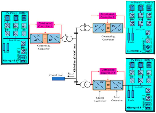
Figure 1.
Structure of interconnected standalone AC microgrids.
The decentralised control of this new structure of interconnected microgrids has been investigated in [2]. It uses equations to relate one microgrid to another so as to determine the power exchange for different power systems and demands. Moreover, the system is balanced as part of its model, representing the steady-state power balance. Still, the proposed structure is yet to be investigated for its optimal performance in dealing with multiple interconnected microgrids, as the existing system automatically exchanges power during periods of power surplus or shortage.
This paper investigates a centralised controller and optimisation of the new structure of multiple standalone microgrids interconnected to a common AC bus using back-to-back converters. The results obtained are compared with those obtained from a non-optimised base case. It is worth mentioning that the main work is focused on a new structure in which multiple standalone microgrids are interconnected to a common AC bus using back-to-back converters with no utility grid connection, and the main objective is to minimise the total cost of energy from the auxiliary unit produced from gas. The performance results obtained are compared with the non-optimised results to determine the percentage of optimal performance of the system. Furthermore, the optimised results determine the total cost of auxiliary energy that the system minimises. The main contributions of this paper are highlighted as follows.
- (a)
- The design of a centralised control and energy management system using the Nelder–Mead simplex algorithm. The system is centrally controlled to optimise the interconnected microgrids at every hour. The optimal dispatch problem is solved using the Nelder–Mead simplex algorithm, which minimises the total energy cost from the auxiliary unit.
- (b)
- The performance evaluation of the proposed optimisation approach in meeting the design requirements, control priorities, and SOC limits is tested under different settings: one-variable optimisation, three-variable optimisation with the standard droop equation, and three-variable optimisation with a modified droop equation. These are tested against three operating conditions:
- (i)
- The independent operation of multiple microgrids;
- (ii)
- Multiple microgrids interconnected with global droop control;
- (iii)
- Multiple microgrids interconnected with global droop control and global load.
- (c)
- The assessment of the proposed approach regarding the optimised total energy cost from the auxiliary unit, compared against a non-optimised benchmark.
- (d)
- The simulation validation of the centralised controller and optimisation algorithm under different operating conditions covering 30 days.
The rest of the paper is organised as follows. Section 2 gives the system description and Section 3 discusses the materials and methods. The results and discussion are presented in Section 4, while the optimised system’s performance analysis is shown in Section 5. Finally, the conclusions are presented in Section 6.
2. System Description
The control model of the standalone interconnected microgrids and the operating conditions to be optimised were described in detail in [2]. Figure 2 presents the interconnected standalone AC microgrids’ centralised control and EMS schematics. The diagram comprises three standalone microgrids interfaced by their corresponding global connecting converters to the common AC bus with a global load. The red dotted line shows a low-link communication network between each microgrid with the corresponding global converter and the EMS. The individual microgrids consist of the following main components: photovoltaic (PV)-based RES units, battery energy storage system (BESS) units, auxiliary units such as the micro gas turbine, and local loads. Each of the three microgrids is connected with the associated global converter, a switch, and a traditional power transformer to a common medium-voltage AC (MVAC) bus (or global bus) and global load.
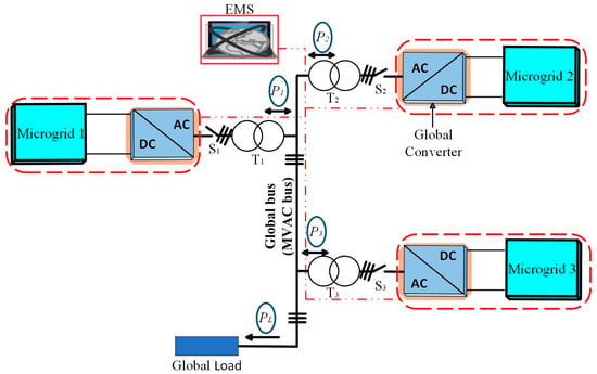
Figure 2.
Schematic of EMS for multiple interconnected standalone microgrids.
Considering the practicality of the overall existing model, each microgrid consists of PV-based RES and load profiles, covering both daily and monthly cycles. Each microgrid can operate individually to meet the local load demand, regardless of the power balance in the neighbouring microgrids. When the microgrids are not interconnected, if one microgrid has a shortage of power and another microgrid has a surplus of power, the microgrid with a shortage will be supplemented with power from the gas-powered auxiliary unit, and the microgrid with a surplus power needs to be curtailed at the full charge of the BESS because the surplus power from the PV-based RES cannot be stored.
At the interconnected microgrid level, the balance between the power exported from the three microgrids and that consumed by the global load is continuously maintained to achieve an optimal energy balance. Individual microgrid units will increase in frequency during a surplus of power or decrease during a power shortage to communicate with other microgrid units and notify other units about the SOC of the BESS. If there is a power shortage, the microgrid will start demanding power, which will be imported from other microgrids. However, suppose that the microgrid is not obtaining the amount of power demanded. In this case, power will begin to be supplemented from the auxiliary unit to maintain the continuity of the supply and reliable operation. There is no direct communication, and power flows from one microgrid to another. However, the system prioritises exporting available power from the PV-based RES over curtailment. Therefore, the system exports power, and, if there is a power surplus, it starts to curtail the PV power. Similarly, the system prioritises importing power from other neighbouring microgrid networks over supplementing it from the auxiliary power supply.
Hence, this paper describes a centralised controller and optimisation of standalone AC microgrids interconnected with a back-to-back power electronic converter as the connecting interface to improve the efficiency and performance of the system in achieving the optimal result, namely minimising the total energy cost by the auxiliary supply unit. The system ensures that the correct amount of power is exchanged between the microgrids and the global load demand is always met. The optimisation algorithm utilises optimal controller operation and balances the power across the interconnected microgrid network.
3. Materials and Methods
3.1. Energy Management Formulation
The structure of the three standalone interconnected microgrids is presented in Figure 2, and the optimisation problem is modelled as a centralised economic dispatch (ED) model of the interconnected microgrids to determine the optimal dispatch solution. Centralised ED and energy management involves consolidating the control and optimisation of interconnected microgrids into a single centralised system with information gathered about every microgrid to maximise the global benefit of the network. By globally controlling and coordinating the power exchange with the interconnected microgrid network, the gas utilisation by the auxiliary supply in each microgrid can be minimised, thereby maximising the overall use of the RES in the interconnected network. The interconnected microgrids utilise RES power as much as possible to meet the demand of the global load automatically and equitably.
3.2. Objective Function Formulation
The centralised optimal economic dispatch of the interconnected microgrid is considered a nonlinear problem and aims to minimise the total energy cost from all of the auxiliary units in the form of micro-gas turbines or diesel generators; hence, the objective function considered is the total energy cost from the auxiliary unit utilised by the interconnected microgrids. However, when fossil fuels like diesel/gas are burned to generate electricity, they release carbon dioxide, trap atmospheric heat, and contribute to global warming. The objective is to minimise the reliance on fossil-fuel-powered sources and utilise more renewable energy sources, which is vital in achieving the net-zero target. Energy generated from PV-based sources utilises the Sun’s natural energy and does not produce carbon emissions during generation. Therefore, to minimise the total energy cost from gas in the interconnected microgrids, Equation (1) is presented to provide the optimal mixture of more affordable and sustainable energy. The exchange of power flow between the global AC bus and the microgrids and vice versa makes the centralised ED problem a robust coupling operation. However, in this problem, the optimisation algorithm is expected to minimise the total cost of gas from the auxiliary supply. Hence, the objective function is formulated as follows:
where OF is the objective function, which is the summation of the cost of gas function . is the summation of the total gas price per kWh (GBP/kWh) multiplied by the amount of gas that the auxiliary unit utilises. The function is optimised for each sample of iteration by the Nelder–Mead simplex algorithm. Due to the complex nature of the existing Simulink model and the large amount of computational time required for each iteration, a derivative-free and unconstrained optimisation strategy known as the Nelder–Mead simplex algorithm in MATLAB is employed.
3.3. Operation of the Nelder–Mead Optimisation Algorithm
The proposed model can be solved using the Nelder–Mead simplex optimisation algorithm, a non-derivative-based optimisation method, as described in [56]. The algorithm uses a simplex of points for n-dimensional vectors . Figure 3 illustrates how the algorithm first creates a simplex around the initial point guess at or by adding 5% of each component to .
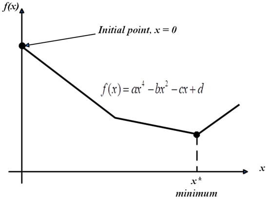
Figure 3.
Schematic of the objective function against the design variables and minimum (x*).
The Nelder–Mead simplex algorithm sets up a simplex with vertices over four steps: reflection, expansion, contraction, and shrinkage [56,57]. The simplex vertices are designed to minimise the mathematical functions of several parameters by replacing the worst vertex with a better found vertex. This algorithm aims to achieve the minimisation of the function in Equation (3) that has n real parameters without constraints:
where the function is the objective function, and is the parameter vector.
The first stage is to create an initial simplex, a collection of vertices in the n-dimensional space, and evaluate the fitness function to identify the optimal vertex. The simplex search of the cost function is evaluated at each of the vertices and reordered according to the cost function values to satisfy . As illustrated in Figure 4, the best, second-worst, and worst vertices are denoted by the subscripts , and , respectively, and and .
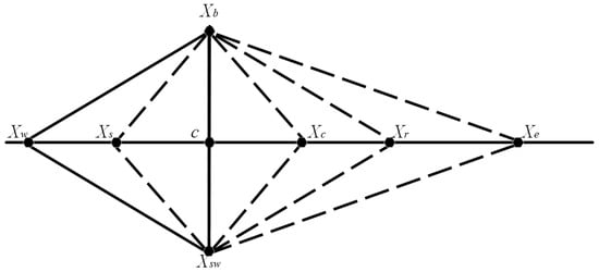
Figure 4.
Illustration of the basic operation of the Nelder–Mead optimisation algorithm.
The centroid of the simplex is the base point of all of the vertices, excluding the worst vertex, and it is computed as shown in Equation (4).
Next, the algorithm explores the landscape of the function along the line segment that joins the centroid and the worst vertex and implements the four different operations using Equation (5) and different values of the standard coefficient , as suggested by Nelder–Mead:
Interestingly, the method used to compute determines the extent of the next simplex. In cases where the new vertex has the lowest cost function, it is a candidate to replace the worst vertex. With a different form and a lesser function value at the worst vertex, the existence of the succeeding, constituting simplex is thus assured. This procedure is repeated iteratively until the minimum point’s coordinates are determined as follows:
where the standard coefficient for reflection is 1, and
However, the shrinkage or reduction operation shrinks the whole simplex towards the best and returns new vertices, and it is used when the previous steps cannot produce any further progress. Therefore, we have
The logical formulas presented in Algorithm 1 illustrate how the Nelder–Mead algorithm determines a minimal point.
| Algorithm 1: The Standard Nelder–Mead Algorithm’s Logical Choices for a Single Iteration |
| Sort the simplex vertices, |
| and , |
| if then |
| Case1: (either reflection or expansion) |
| else |
| Case2: (either contraction or shrinkage) |
| end if |
| Case1: Case2: |
| if then if then |
| if then if then |
| Replace with Replace with |
| else else if then |
| Replace with Replace with |
| end if else Reduction |
| else end if |
| Replace with else Reduction |
| end if end if |
It is a design space with two dimensions if single-variable optimisation is considered, and the objective function is plotted against the design variables . Still, it can have any number of dimensions or sizes. However, is the notation for the minimum. Hence, the Nelder–Mead simplex algorithm minimises the objective function by starting from an initial point in the search space [58,59]. This initial point or guess does not have to be perfect because the simplex algorithm searches the design space to find the minimum. It is important to note that the Nelder–Mead simplex is applied for unconstrained problems and does not require any derivative information from the system. It is called unconstrained nonlinear optimisation because it finds the minimum of a scalar function of several variables, starting at an initial guess value, through repeated searching.
3.4. Realisation of the Proposed Nelder–Mead Simplex Optimisation Algorithm
Simulations of the proposed centralised control and optimal energy management of multiple interconnected standalone microgrids were carried out in three cases. The first case simulation was carried out as single-variable optimisation, as described in the EMS flow model shown in Figure 5. This was unconstrained optimisation performed using a single gain value, “”, and the total auxiliary power from the three interconnected microgrids. The optimal operating cost was obtained and recorded as the minimal energy cost, representing the lowest objective function value. The second simulation case was three-variable optimisation performed using three gain values, “”, as illustrated in the EMS flow model in Figure 6.
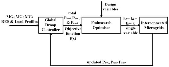
Figure 5.
EMS workflow model for single-variable optimisation.
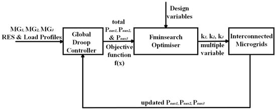
Figure 6.
EMS workflow model for three-variable optimisation.
The simulation was carried out in two phases as follows.
(i) The first involved the global droop controller equation left as described in Equation (13) of [2], namely
(ii) The second involved a modified global droop controller equation obtained by changing the droop equation from proportional to proportional–integral control. Hence, the entirety of the power export demand in all microgrids was equal to the power demanded by the microgrid, and Equation (11) could be modified as
Similarly, this is unconstrained optimisation performed using three variables and the total auxiliary power from the three interconnected microgrids. The optimal operating cost is also obtained and recorded as the overall lowest gas cost, representing the lowest objective function value.
Hence, the algorithm can be formulated as follows.
- (i)
- Single-variable optimisation:
- (ii)
- Three-variable optimisation: with the standard droop equation
- (iii)
- Three-variable optimisation: with a modified droop equation such as .
where k is the proportional gain that relates the frequency deviation to the power setpoints, as illustrated in Figure 3 in [2].
The algorithm was run for different initial points in each optimisation operating case. The results show that the system’s performance improved, and the auxiliary unit’s overall cost of energy utilisation was minimised in both the single- and three-variable simulation cases as compared to the benchmark results. It can be observed from the objective function results in Figure 7, Figure 8 and Figure 9 that no further cost minimisation of the objective function was possible after evaluating each of the last rows of the selected initial points. The initial points used to minimize the overall cost of energy from gas utilised by the auxiliary unit are presented in Table 1. The first initial estimate was chosen as established in [2], while the rest of the initial points were selected from the lowest function values of each iteration.
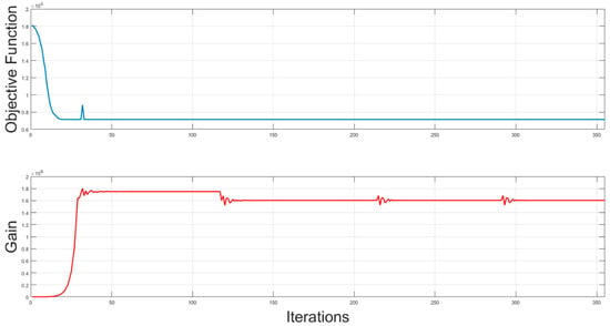
Figure 7.
Nelder–Mead simplex objective function and gain for single-variable optimisation.
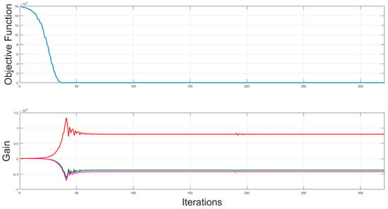
Figure 8.
Nelder–Mead simplex objective function and gain for three-variable optimisation; red, green and pink coloured lines represent gain values for and respectively.
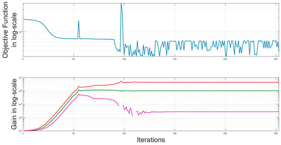
Figure 9.
Nelder–Mead simplex objective function and gain in logarithmic scale for three-variable optimisation with modified global droop equation; red, green and pink coloured lines represent gain in log–scale values for and respectively.

Table 1.
Nelder–Mead simplex algorithm: initial guess values.
The first row of initial points is the case of single-variable optimisation, where a single gain k is selected at each iteration to minimise the objective cost function. The second row of initial points is the multi-variable optimisation, where three rows of gains of different initial points are selected for the three microgrids at each iteration to minimise the objective function. Similarly, the third row of initial points is obtained by repeating the three-variable optimisation iterations with three different rows of gains , with a modified global droop equation (by changing the droop equation from proportional to proportional–integral), such that the power export reference is the same as the power exported for each microgrid and each iteration minimises the objective function.
4. Results and Discussion
4.1. Convergence Characteristics
Figure 7, Figure 8 and Figure 9 present the combined cost-based objective function plots and gains for the algorithm’s three cases of optimisation runs for different initial points. In contrast, Table 2 shows the optimal cost comparison for the three cases against the benchmark. Figure 7 shows that the cost-based objective function values for single-variable optimisation started to be minimised from the initial estimate as the controller gain increased. The minimised cost function maintained a constant value across all iterations, even when the gain dropped below 1.7 × 10⁶, and it was stabilised at about 1.6 × 10⁶. Figure 8 shows that the objective function values for three-variable optimisation started to be minimised from the initial estimate, as the three gains tended to settle at different points at about 50 iterations. The cost function was minimised to a low value at about 40 iterations and maintained this low value even as the three gains maintained a near-constant value for over 300 iterations.

Table 2.
Optimal cost comparison for the three cases against the benchmark.
Figure 9 shows the cost-based objective function in a logarithmic scale (log-scale) for three-variable optimisation with a modified global droop equation, starting to be minimised from the initial gain estimate as the gains shown in the log-scale increase. The cost is minimised to low, unsteady values at about 100 iterations, while the three gains maintain steady values at about 100 iterations.
4.2. System Performance after Optimisation
The proposed Nelder–Mead simplex algorithm’s performance in terms of centralised control for interconnected microgrids is compared with overall cost minimisation based on the initial sensitivity, convergence, and scalability. Table 3 summarises the performance evaluation categories.

Table 3.
Summary of the performance categories.
- (i)
- Comparison based on initial sensitivity
The influence of the initial gains is evaluated on the objective function. Different evolution sets of gains are sampled during the simulation, and their corresponding optimal objective function values represent good stability regarding their respective initial sensitivities. However, the initial sensitivity plot for single-variable optimisation in Figure 6 shows that the objective function appears to be stable in the second sample of initial sensitivity values, irrespective of the changes in the initial gain between the second and fourth initial values.
- (ii)
- Comparison based on convergence
The evaluation of the convergence based on the three cases of optimisation simulation runs shows that the optimisation process converges at different numbers of iterations. Figure 6 shows the convergence curve of the objective function after 418 iterations for single-variable optimisation. The curve represents and maintains a consistent objective cost over 418 iterations. Meanwhile, cases (i) and (ii) for three-variable optimisation converge at about 40 and 90 iterations, respectively, and both results render the system unstable.
- (iii)
- Comparison based on scalability
Scalability, in this case, is the ability of the centralised control system of interconnected microgrids to continue functioning effectively, irrespective of its size, to meet the user demand. The performance of the centralised control method proposed in this work is used to solve the ED problem. The calculation result is compared with the benchmark based on the single-variable and multiple-variable centralised optimisation methods. Based on the performance results obtained after convergence, the optimal solution is obtained in the case of single-variable optimisation in terms of maintaining the standard of comparison with the benchmark. The two conditions for multi-variable optimisation show sub-optimal performance, and the system is unstable at a lower cost function. Hence, they are not considered further in our simulation studies.
5. Optimised System Performance Analysis
This section shows the results of the centralised control of multiple interconnected standalone microgrids, tested on the Nelder–Mead simplex optimisation algorithm, based on the single-variable optimisation algorithm. The centralised control and energy management of three standalone microgrids interconnected to a common AC bus with a global load via a static switch, back-to-back converter, and traditional power transformers is presented in Figure 2. However, all of the system parameters used during the simulations are provided in [2].
This research aims to solve the optimal power dispatch of the centralised control and energy management of multiple interconnected standalone microgrids. Each microgrid consists of a PV-based RES unit, BESS unit, auxiliary unit, and load. Daily data profiles measured over 24 h represent the available RES units and load demands. As an economic dispatch problem, this research solves the centralised control and energy management of multiple interconnected microgrid economic dispatch problems based on the measured 24 h data. A detailed model of the three interconnected microgrids was built in MATLAB/Simulink R2023a. The effect of each standalone microgrid’s auxiliary power generation cost on the interconnected microgrid is not utilised based on the centralised control topology. Instead, the total cost of the auxiliary unit is used as input to minimise the total cost of gas. Therefore, the cost per kilowatt-hour (kWh) of power generated by the total auxiliary units varies based on the individual microgrids’ consumption. This system is modelled as a centralised unit with single-variable optimisation, having multiple-area economic dispatch problems, since each microgrid operates autonomously.
The proposed multiple standalone interconnected microgrids with three different microgrids and the global load are optimised, and the schematic diagram is also shown in Figure 2. The optimised results are compared with those of the non-optimised benchmark obtained, regarding the amount of gas that the auxiliary unit saves. Therefore, using the proposed Nelder–Mead simplex optimisation algorithm in MATLAB/Simulink to solve the ED problem of the interconnected standalone microgrids, the following corresponding case-by-case optimal dispatching results for the three different microgrids are as shown in Figure 10, Figure 11 and Figure 12. These are based on case A for independently operated microgrids, case B for interconnected microgrids with global droop control, and case C for interconnected microgrids with global droop control and a global load, respectively.
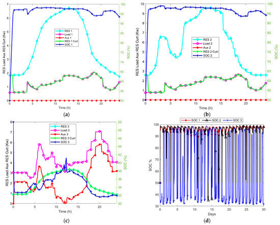
Figure 10.
(a–d) Optimal dispatch curves of independently operated microgrids at (30–100)% SOC: (a) microgrid one, (b) microgrid two, (c) microgrid three. (d) Dispatch curves for 30-day SOC.
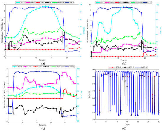
Figure 11.
(a–d) Optimal dispatch curves of interconnected microgrids with global droop control at (30–100)% SOC: (a) microgrid one, (b) microgrid two, (c) microgrid three. (d) Dispatch curves for 30-day SOC.
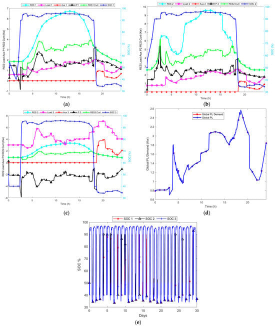
Figure 12.
(a–e) Optimal dispatch curves of interconnected microgrids with global droop control and load at (30–100)% SOC: (a) microgrid one, (b) microgrid two, (c) microgrid three. (d) Global load dispatch curve and (e) dispatch curves for 30-day SOC.
- Case A: Optimal Dispatch Results for Independently Operated Microgrids
The optimal dispatching results in Figure 10 have been tested and show no significant difference. All dispatch SOC curves are within range, implying that the microgrids are not optimised when operating independently. When operated with an optimised gain selected based on minimising the total cost of auxiliary energy, it implies that, at some point, the microgrids can be seen to reduce the use of energy from gas in different sets of profiles. Figure 10a,b show that the available RES energy in microgrids one and two is used to meet the load demand, their respective surpluses are curtailed, and no energy from the auxiliary unit is supplied. Figure 10c shows that microgrid three supplies all of its available RES energy, which is not sufficient to meet the load demand, and this shortage triggers a supply from the auxiliary unit. The auxiliary unit supplies the deficit energy to meet the load demand.
- Case B: Optimal Dispatch Results for Interconnected Microgrids with Global Droop Control
The optimal dispatch results in Figure 11 show a daily reduction in the cost of the total energy utilised from the auxiliary unit, and more energy from the PV-based RES is exported and used to meet the load demand. Figure 11a–c show that the auxiliary unit in the three interconnected microgrids only supplies energy when needed and when there is an insufficient supply from the RES. Moreover, Figure 11a,b show that a significant amount of energy is exported from microgrids one and two, with a surplus from RES, resulting in more energy imported to microgrid three. The energy imported from microgrids one and two into microgrid three causes an overall reduction in energy usage from the auxiliary unit powered by gas. Figure 11d shows that the SOC maintains its boundaries within the optimal operation of the interconnected microgrids.
- Case C: Optimal Dispatch Results for Interconnected Microgrids with Global Droop Control and Global Load
The optimal dispatch results in Figure 12 show a daily reduction in the cost of the total energy utilised from the auxiliary unit, and greater energy from the PV-based RES is exported from microgrids one and two to microgrid three to meet the load demands, as well as meeting the load demand of the global load. Similarly, Figure 12a–c show that the auxiliary unit in the three interconnected microgrids only supplies energy when needed and when there is an insufficient supply from the RES. Moreover, Figure 12a,b show that more energy is exported from microgrids one and two, with a surplus from RES, resulting in more energy imported to microgrid three. The energy imported from microgrids one and two into microgrid three causes an overall reduction in energy usage from the gas-powered auxiliary unit. Figure 12d also shows that more energy from RES is used to meet the global load demand. Figure 12e indicates that the SOC maintains its boundaries within the optimal operation of the interconnected microgrids.
Figure 13 and Figure 14 show the optimal RES energy curtailed and the optimal auxiliary energy utilised over 30 days when the microgrids are independently operated, for the interconnected microgrids, and for the interconnected microgrids with a global load, respectively. Figure 13 shows that more RES energy is utilised to meet the load demand. Figure 14 shows massive reductions in the use of gas over 30 days, which increases when the interconnected microgrids are connected to the global load. However, the lowest use of gas from the auxiliary unit is recorded when the interconnected microgrids are operated with a global droop controller. The highest use of gas is recorded when the microgrids are operated independently, representing the non-optimised case.
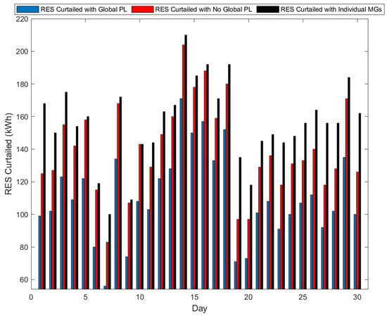
Figure 13.
Optimal RES energy curtailed with individually operated microgrids, those interconnected with the global droop controller, and those with the global droop controller and the load.
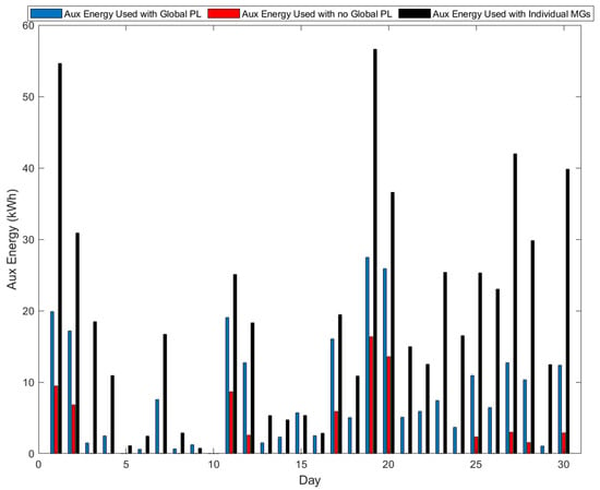
Figure 14.
Optimal auxiliary energy utilised with individually operated microgrids, interconnected microgrids with the global droop controller, and those with the global droop controller and load.
Figure 15 and Figure 16 show the optimal total RES energy curtailed and the optimal total auxiliary energy utilised when the microgrids are independently operated, for the interconnected microgrids with global droop control, and for the interconnected microgrids with global droop control and a global load, respectively. Figure 15 shows that, overall, more RES energy is utilised to meet the energy demands of the interconnected microgrids. In contrast, Figure 16 shows that, overall, there is an optimal total reduction in the use of gas to meet the load demand. The case in which the microgrids are interconnected with the global droop controller shows the largest reduction in gas, followed by that in which the interconnected microgrids are connected with the global load, while the individual microgrid operation case shows the optimal highest use of energy from gas. Table 4 shows the details of the total optimal auxiliary energy comparison with the percentage reduction between the non-optimised and optimised cases. A detailed evaluation of the simulation results shows that the control strategy is optimal, and the result shows that the total optimal auxiliary energy is reduced by 8.98%. Hence, the optimised case outperforms the non-optimised case.
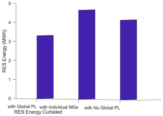
Figure 15.
Optimal total RES energy curtailed with individually operated microgrids, interconnected microgrids with the global droop controller, and those with the global droop controller and load.
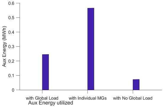
Figure 16.
Optimal total auxiliary energy utilised with individually operated microgrids, interconnected microgrids with the global droop controller, and those with the global droop controller and load.

Table 4.
Optimal auxiliary energy comparison with % reduction between the cases.
6. Conclusions
This paper presents the centralised control and energy management of multiple standalone microgrids interconnected via back-to-back converters to a common AC bus with a global load to minimise the overall cost of auxiliary energy while maximising the use of RES energy. The economic dispatch model was created based on the original concept presented in [2]. The interconnected network of microgrids was viewed as a single entity with diverse networks, capable of operating independently and cooperatively to meet the local and global load demand. Based on this, centralised control and energy management were carried out in a dispatch model using the Nelder–Mead simplex algorithm. The daily total energy cost from the auxiliary unit was used to determine the optimality of this optimisation technique. The optimisation algorithm was implemented based on three case scenarios, consisting of single-variable optimisation and multiple-variable optimisation, considering two cases with the global droop equation left as in Equation (11) and one with a modified global droop equation, in which the droop equation was changed from proportional to proportional–integral, as in Equation (12). The results showed that the single-variable optimisation minimised the overall energy cost from the auxiliary unit and maintained the SOC within the predetermined limit. While the results from the two cases of three-variable optimisation showed some consistency in terms of objective cost minimisation, the system’s performance was unstable over the iterations. It did not satisfy the requirements in terms of scalability, as summarised by the performance categories in Table 3, or in the comparison with the single-variable results. Furthermore, the single-variable simulation results showed that the optimised centralised control and energy management network outperformed the benchmark and minimised the total cost of auxiliary energy by 8.98% compared to the non-optimised benchmark. This research shows that, based on a single-variable optimisation approach, it is possible to regulate the total energy utilisation from the auxiliary unit, thereby utilising more energy from the PV-based RES to meet the load demand.
Author Contributions
Conceptualisation, E.U., S.D. and M.A.; methodology, E.U., S.D. and M.A.; software, E.U., S.D. and M.A.; validation, S.D. and M.A.; formal analysis, E.U.; investigation, E.U.; resources, E.U.; data curation, E.U.; writing—original draft preparation, E.U.; writing—review and editing, S.D. and M.A.; visualisation, E.U.; supervision, S.D. and M.A.; project administration, M.A.; funding acquisition, E.U. All authors have read and agreed to the published version of the manuscript.
Funding
This research was funded by the Tertiary Education Trust Fund (TETFUND) under the Federal University of Petroleum Resources, Effurun, Nigeria, AST&D 2018 intervention, grant number FUPRE/TO/AST&D/2018.
Data Availability Statement
The data are available from the corresponding author upon reasonable request.
Acknowledgments
For the purpose of open access, the authors have applied a Creative Commons Attribution (CC BY) license to this manuscript.
Conflicts of Interest
The authors declare no conflicts of interest. The funders had no role in the design of the study; in the collection, analyses, or interpretation of the data; in the writing of the manuscript; or in the decision to publish the results.
Nomenclature
| Acronym | Description |
| AC | Alternating current |
| Aux | Auxiliary |
| BESS | Battery energy storage system |
| DC | Direct current |
| ED | Economic dispatch |
| EMS | Energy management system |
| kWh | Kilowatt-hour |
| MPC | Model predictive control |
| MVAC | Medium-voltage alternating current |
| Min | Minimisation |
| OF | Objective function |
| PSO | Particle swarm optimisation |
| PV | Photovoltaic |
| RES | Renewable energy sources |
| SOC | State of charge |
| Summation of cost of gas function | |
| Cost of energy from gas per kWh (GBP/kWh) | |
| Total amount of gas utilised by auxiliary unit | |
| cx + d) | Nonlinear function |
| Notation for minimum | |
| Initial point in search space | |
| x | Design variable |
| f(x) | Objective function of nonlinear function |
| Power export of microgrid | |
| Power export demand of microgrid | |
| Total number of connecting global converters | |
| Average power export demand | |
| Load at global bus | |
| Vertices | |
| Best vertex | |
| Second-worst vertex | |
| Worst vertex | |
| Contraction | |
| Reflection vertex | |
| Expansion vertex | |
| Shrinkage vertex | |
| Outer contraction vertex | |
| New vertex | |
| Nelder–Mead standard coefficient | |
| Standard coefficient for reflection | |
| Standard coefficient for expansion | |
| Standard coefficient for outer contraction | |
| Standard coefficient for inner contraction | |
| Standard coefficient for shrinkage | |
| Centroid |
References
- Uddin, M.; Mo, H.; Dong, D.; Elsawah, S.; Zhu, J.; Guerrero, J.M. Microgrids: A review, outstanding issues and future trends. Energy Strategy Rev. 2023, 49, 101127. [Google Scholar] [CrossRef]
- Udoha, E.; Das, S.; Abusara, M. Power Flow Management of Interconnected AC Microgrids Using Back-to-Back Converters. Electronics 2023, 12, 3765. [Google Scholar] [CrossRef]
- Udoha, E.; Das, S.; Abusara, M. A power management system for interconnected AC islanded microgrids using back-to-back converter. In Proceedings of the Renewable Power Generation and Future Power Systems Conference 2023 (RPG 2023 UK), Glasgow, UK, 15–16 November 2023; pp. 177–183. [Google Scholar] [CrossRef]
- Zou, H.; Mao, S.; Wang, Y.; Zhang, F.; Chen, X.; Cheng, L. A Survey of Energy Management in Interconnected Multi-Microgrids. IEEE Access 2019, 7, 72158–72169. [Google Scholar] [CrossRef]
- Grami, M.; Rekik, M.; Krichen, L. A Power management Strategy for Interconnected Microgrids. In Proceedings of the 20th International Conference on Sciences and Techniques of Automatic Control & Computer Engineering (STA), Sfax, Tunisia, 20–22 December 2020; pp. 213–218. [Google Scholar] [CrossRef]
- Lu, T.; Wang, Z.; Ai, Q.; Lee, W.J. Interactive model for energy management of clustered microgrids. In Proceedings of the IEEE Industry Applications Society Annual Meeting, Portland, OR, USA, 2–6 October 2016. [Google Scholar] [CrossRef]
- Shahnia, F.; Chandrasena, R.P.; Rajakaruna, S.; Ghosh, A. Autonomous Operation of Multiple Interconnected Microgrids with Self—Self-healing capability. In Proceedings of the 2013 IEEE Power & Energy Society General Meeting, Vancouver, BC, Canada, 21–25 July 2013. [Google Scholar] [CrossRef]
- Thirugnanam, K.; El Moursi, M.S.; Khadkikar, V.; Zeineldin, H.H.; Al Hosani, M. Energy Management of Grid Interconnected Multi-Microgrids Based on P2P Energy Exchange: A Data Driven Approach. IEEE Trans. Power Syst. 2021, 36, 1546–1562. [Google Scholar] [CrossRef]
- Gamage, D.; Zhang, X.; Ukil, A.; Swain, A. Energy Management of Islanded Interconnected Dual Community Microgrids. In Proceedings of the IECON 2020 The 46th Annual Conference of the IEEE Industrial Electronics Society, Singapore, 18–21 October 2020; pp. 1803–1807. [Google Scholar] [CrossRef]
- Naderi, M.; Khayat, Y.; Shafiee, Q.; Dragicevic, T. An Emergency Active and Reactive Power Exchange Solution for Interconnected Microgrids. IEEE J. Emerg. Sel. Top. Power Electron. 2021, 9, 5206–5218. [Google Scholar] [CrossRef]
- Pham, M.C.; Razi, R.; Hably, A.; Bacha, S.; Tran, Q.T.; Iman-Eini, H. Power management in multi-microgrid system based on energy routers. In Proceedings of the IEEE International Conference on Industrial Technology (ICIT), Buenos Aires, Argentina, 26–28 February 2020. [Google Scholar] [CrossRef]
- Zhou, B.; Zou, J.; Chung, C.Y.; Wang, H.; Liu, N.; Voropai, N.; Xu, D. Multi-microgrid Energy Management Systems: Architecture, Communication, and Scheduling Strategies. J. Mod. Power Syst. Clean Energy 2021, 9, 463–476. [Google Scholar] [CrossRef]
- Mavuri, S.S.; Nakka, J.; Kotla, A. Interconnected Microgrids: A Review and Future perspectives. In Proceedings of the 2022 IEEE 2nd International Conference on Sustainable Energy and Future Electric Transportation, SeFeT 2022, Hyderabad, India, 4–6 August 2022. [Google Scholar] [CrossRef]
- Saha, D.; Bazmohammadi, N.; Vasquez, J.C.; Guerrero, J.M. Multiple Microgrids: A Review of Architectures and Operation and Control Strategies. Energies 2023, 16, 600. [Google Scholar] [CrossRef]
- Ma, G.; Li, J.; Zhang, X.P. A Review on Optimal Energy Management of Multimicrogrid System Considering Uncertainties. IEEE Access 2022, 10, 77081–77098. [Google Scholar] [CrossRef]
- Nikmehr, N.; Ravadanegh, S.N. Optimal Power Dispatch of Multi-Microgrids at Future Smart Distribution Grids. IEEE Trans. Smart Grid 2015, 6, 1648–1657. [Google Scholar] [CrossRef]
- Ouammi, A.; Dagdougui, H.; Dessaint, L.; Sacile, R. Coordinated Model Predictive-Based Power Flows Control in a Cooperative Network of Smart Microgrids. IEEE Trans. Smart Grid 2015, 6, 2233–2244. [Google Scholar] [CrossRef]
- Ceja-Espinosa, C.; Pirnia, M.; Cañizares, C.A. A Privacy-Preserving Energy Management System for Cooperative Multi-Microgrid Networks. In Proceedings of the 11th Bulk Power Systems Dynamics and Control Symposium (IREP 2022), Banff, AB, Canada, 25–30 July 2022. [Google Scholar]
- Arefifar, S.A.; Ordonez, M.; Mohamed, Y.A.R.I. Energy Management in Multi-Microgrid Systems—Development and Assessment. IEEE Trans. Power Syst. 2017, 32, 910–922. [Google Scholar] [CrossRef]
- Elshenawy, M.; Fahmy, A.; Elsamahy, A.; Kandil, S.A.; Zoghby, H.M.E. Optimal Power Management of Interconnected Microgrids Using Virtual Inertia Control Technique. Energies 2022, 15, 7026. [Google Scholar] [CrossRef]
- Wang, Z.; Chen, B.; Wang, J.; Begovic, M.M.; Chen, C. Coordinated energy management of networked microgrids in distribution systems. IEEE Trans. Smart Grid 2015, 6, 45–53. [Google Scholar] [CrossRef]
- Zhong, X.; Zhong, W.; Liu, Y.; Yang, C.; Xie, S. Optimal energy management for multi-energy multi-microgrid networks considering carbon emission limitations. Energy 2022, 246, 123428. [Google Scholar] [CrossRef]
- Dabbaghjamanesh, M.; Mehraeen, S.; Kavousi-Fard, A.; Ferdowsi, F. A New Efficient Stochastic Energy Management Technique for Interconnected AC Microgrids. In Proceedings of the IEEE Power and Energy Society General Meeting 2018, Portland, OR, USA, 5–10 August 2018. [Google Scholar] [CrossRef]
- Song, N.O.; Lee, J.H.; Kim, H.M.; Im, Y.H.; Lee, J.Y. Optimal energy management of multi-microgrids with sequentially coordinated operations. Energies 2015, 8, 8371–8390. [Google Scholar] [CrossRef]
- Naz, K.; Zainab, F.; Mehmood, S.B.A.; Bukhari, K.K.; Khalid, H.A.; Kim, C. An Optimized Framework for Energy Management of Multi-Microgrid Systems. Energies 2021, 14, 6012. [Google Scholar] [CrossRef]
- Zhao, B.; Wang, X.; Lin, D.; Calvin, M.M.; Morgan, J.C.; Qin, R.; Wang, C. Energy Management of Multiple Microgrids Based on a System of Systems Architecture. IEEE Trans. Power Syst. 2018, 33, 6410–6421. [Google Scholar] [CrossRef]
- Liu, W.; Zhan, J.; Chung, C.Y. A novel transactive energy control mechanism for collaborative networked microgrids. IEEE Trans. Power Syst. 2019, 34, 2048–2060. [Google Scholar] [CrossRef]
- Bullich-Massagué, E.; Díaz-González, F.; Aragüés-Peñalba, M.; Girbau-Llistuella, F.; Olivella-Rosell, P.; Sumper, A. Microgrid clustering architectures. Appl. Energy 2018, 212, 340–361. [Google Scholar] [CrossRef]
- Xie, M.; Ji, X.; Hu, X.; Cheng, P.; Du, Y.; Liu, M. Autonomous optimized economic dispatch of active distribution system with multi-microgrids. Energy 2018, 153, 479–489. [Google Scholar] [CrossRef]
- Li, F.; Qin, J.; Wan, Y.; Yang, T. Decentralized Cooperative Optimal Power Flow of Multiple Interconnected Microgrids via Negotiation. IEEE Trans. Smart Grid 2020, 11, 3827–3836. [Google Scholar] [CrossRef]
- Liu, Z.; Yi, Y.; Yang, J.; Tang, W.; Zhang, Y.; Xie, X.; Ji, T. Optimal planning and operation of dispatchable active power resources for islanded multi-microgrids under decentralised collaborative dispatch framework. IET Gener. Transm. Distrib. 2020, 14, 408–422. [Google Scholar] [CrossRef]
- Mthethwa, F.; Gomes, C.; Dorrell, D. Development of optimal algorithm to interconnect multiple microgrids in an agricultural-based remote community. In Proceedings of the IEEE AFRICON Conference, Arusha, Tanzania, 13–15 September 2021. [Google Scholar] [CrossRef]
- Hidalgo-Rodríguez, D.I.; Myrzik, J. Optimal Operation of Interconnected Home-Microgrids with Flexible Thermal Loads: A Comparison of Decentralized, Centralized, and Hierarchical-Distributed Model Predictive Control. In Proceedings of the 2018 Power Systems Computation Conference (PSCC), Dublin, Ireland, 11–15 June 2018. [Google Scholar] [CrossRef]
- Schneider, K.P.; Miller, C.; Laval, S.; Du, W.; Ton, D. Networked Microgrid Operations: Supporting a Resilient Electric Power Infrastructure. IEEE Electrif. Mag. 2020, 8, 70–79. [Google Scholar] [CrossRef]
- Kampezidou, S.; Vasios, O.; Meliopoulos, S. Multi-Microgrid Architecture: Optimal Operation and Control. In Proceedings of the North American Power Symposium (NAPS), Fargo, ND, USA, 9–11 September 2018. [Google Scholar] [CrossRef]
- Ouammi, A.; Dagdougui, H.; Sacile, R. Optimal control of power flows and energy local storages in a network of microgrids modeled as a system of systems. IEEE Trans. Control Syst. Technol. 2015, 23, 128–138. [Google Scholar] [CrossRef]
- Sheikhahmadi, P.; Bahramara, S.; Mazza, A.; Chicco, G.; Shafie-Khah, M.; Catalao, J.P.S. Multi-Microgrids Operation with Interruptible Loads in Local Energy and Reserve Markets. IEEE Syst. J. 2023, 17, 1292–1303. [Google Scholar] [CrossRef]
- Zhang, W.; Xu, Y. Distributed Optimal Control for Multiple Microgrids in a Distribution Network. IEEE Trans. Smart Grid 2019, 10, 3765–3779. [Google Scholar] [CrossRef]
- Hussain, A.; Bui, V.H.; Kim, H.M. A Resilient and Privacy-Preserving Energy Management Strategy for Networked Microgrids. IEEE Trans. Smart Grid 2018, 9, 2127–2139. [Google Scholar] [CrossRef]
- Nikmehr, N.; Najafi-Ravadanegh, S.; Khodaei, A. Probabilistic optimal scheduling of networked microgrids considering time-based demand response programs under uncertainty. Appl. Energy 2017, 198, 267–279. [Google Scholar] [CrossRef]
- Haghifam, S.; Dadashi, M.; Zare, K.; Seyedi, H. Optimal operation of smart distribution networks in the presence of demand response aggregators and microgrid owners: A multi follower Bi-Level approach. Sustain. Cities Soc. 2020, 55, 102033. [Google Scholar] [CrossRef]
- Mohiti, M.; Monsef, H.; Anvari-Moghaddam, A.; Guerrero, J.; Lesani, H. A decentralized robust model for optimal operation of distribution companies with private microgrids. Int. J. Electr. Power Energy Syst. 2019, 106, 105–123. [Google Scholar] [CrossRef]
- Hussain, A.; Bui, V.H.; Kim, H.M. Robust optimization-based scheduling of multi-microgrids considering uncertainties. Energies 2016, 9, 278. [Google Scholar] [CrossRef]
- Du, Y.; Wu, J.; Li, S.; Long, C.; Onori, S. Coordinated Energy Dispatch of Autonomous Microgrids with Distributed MPC Optimization. IEEE Trans. Ind. Inform. 2019, 15, 5289–5298. [Google Scholar] [CrossRef]
- Wu, X.; Xu, Y.; Wu, X.; He, J.; Guerrero, J.M.; Liu, C.C.; Schneider, K.P.; Ton, D.T. A Two-Layer Distributed Cooperative Control Method for Islanded Networked Microgrid Systems. IEEE Trans. Smart Grid 2020, 11, 942–957. [Google Scholar] [CrossRef]
- Kong, X.; Liu, D.; Wang, C.; Sun, F.; Li, S. Optimal operation strategy for interconnected microgrids in market environment considering uncertainty. Appl. Energy 2020, 275, 115336. [Google Scholar] [CrossRef]
- Jafari, A.; Ganjehlou, H.G.; Khalili, T.; Bidram, A. A fair electricity market strategy for energy management and reliability enhancement of islanded multi-microgrids. Appl. Energy 2020, 270, 115170. [Google Scholar] [CrossRef]
- Fan, S.; Xu, G.; Ai, Q.; Gao, Y. Community Market Based Energy Trading Among Interconnected Microgrids with Adjustable Power. IEEE Trans. Ind. Appl. 2023, 59, 148–159. [Google Scholar] [CrossRef]
- Wang, Z.; Chen, B.; Wang, J.; Kim, J. Decentralized Energy Management System for Networked Microgrids in Grid-Connected and Islanded Modes. IEEE Trans. Smart Grid 2016, 7, 1097–1105. [Google Scholar] [CrossRef]
- El Zerk, A.; Ouassaid, M.; Zidani, Y. Decentralised strategy for energy management of collaborative microgrids using multi-agent system. IET Smart Grid 2022, 5, 440–462. [Google Scholar] [CrossRef]
- Mukhopadhyay, B.; Das, D. Comprehensive multi-benefit planning of sustainable interconnected microgrids. Sustain. Energy Grids Netw. 2023, 36, 101226. [Google Scholar] [CrossRef]
- Chen, X.; Zhai, J.; Jiang, Y.; Ni, C.; Wang, S.; Nimmegeers, P. Decentralized coordination between active distribution network and multi-microgrids through a fast decentralized adjustable robust operation framework. Sustain. Energy Grids Netw. 2023, 34, 101068. [Google Scholar] [CrossRef]
- Li, Y.; Zhao, T.; Wang, P.; Gooi, H.B.; Wu, L.; Liu, Y.; Ye, J. Optimal operation of multimicrogrids via cooperative energy and reserve scheduling. IEEE Trans. Ind. Inform. 2018, 14, 3459–3468. [Google Scholar] [CrossRef]
- Du, Y.; Li, F. Intelligent Multi-Microgrid Energy Management Based on Deep Neural Network and Model-Free Reinforcement Learning. IEEE Trans. Smart Grid 2020, 11, 1066–1076. [Google Scholar] [CrossRef]
- Wang, Z.; Dou, Z.; Dong, J.; Si, S.; Wang, C.; Liu, L. Optimal Dispatching of Regional Interconnection Multi-Microgrids Based on Multi-Strategy Improved Whale Optimization Algorithm. IEEJ Trans. Electr. Electron. Eng. 2022, 17, 766–779. [Google Scholar] [CrossRef]
- Audet, C.; Hare, W.; Audet, C.; Hare, W. Nelder-mead. In Derivative-Free and Blackbox Optimization; Springer: Berlin/Heidelberg, Germany, 2017; pp. 75–91. [Google Scholar] [CrossRef]
- Vasiliev, I.; Luca, L.; Vilanova, R.; Caraman, S. Optimal Control of a Sewer Network. In Proceedings of the 2022 26th International Conference on System Theory, Control and Computing, ICSTCC 2022—Proceedings, Sinaia, Romania, 19–21 October 2022; pp. 80–85. [Google Scholar] [CrossRef]
- Lagarias, J.C.; Reeds, J.A.; Wright, M.H.; Wright, P.E. Convergence properties of the Nelder-Mead simplex method in low dimensions. SIAM J. Optim. 1998, 9, 112–147. [Google Scholar] [CrossRef]
- Gao, F.; Han, L. Implementing the Nelder-Mead simplex algorithm with adaptive parameters. Comput. Optim. Appl. 2012, 51, 259–277. [Google Scholar] [CrossRef]
Disclaimer/Publisher’s Note: The statements, opinions and data contained in all publications are solely those of the individual author(s) and contributor(s) and not of MDPI and/or the editor(s). MDPI and/or the editor(s) disclaim responsibility for any injury to people or property resulting from any ideas, methods, instructions or products referred to in the content. |
© 2024 by the authors. Licensee MDPI, Basel, Switzerland. This article is an open access article distributed under the terms and conditions of the Creative Commons Attribution (CC BY) license (https://creativecommons.org/licenses/by/4.0/).
