Abstract
To address the issues of high computational load and slow dynamic performance in traditional fractional-order sliding mode control for LCL-type grid-connected inverters, this paper proposes a fixed-time robust fractional-order sliding mode control strategy based on weighted average current control. Firstly, the weighted average current control (WACC) is used to reduce the third-order LCL filter to the first order, which simplifies the system model; secondly, in order to suppress the disturbance caused by the filter parameter perturbation to the weighted average current accuracy, a fixed-time disturbance observer (FTDO) is used to quickly estimate the disturbance caused by the filter parameter perturbation in a fixed time, so as to improve the anti-interference ability of the system; moreover, a fixed-time fractional-order sliding mode controller (FTFOSMC) is designed to achieve rapid tracking of the incoming reference current, and the stability of the proposed control strategy is confirmed by the strict Lyapunov method, which proves that the upper bound of the stability time is independent of the initial state of the system. Finally, simulation and experimental results show that the proposed method has better steady-state performance and a higher dynamic performance.
1. Introduction
In recent years, the rise in energy consumption has underscored the importance of renewable energy, and technologies like photovoltaic and wind power have seen rapid development. In renewable energy power generation, the inverter is an important device between green energy sources and the power grid [1,2]. Filters are often employed to remove high-order harmonics, improving the grid-connected current quality. LCL-type filters surpass L-type and LC-type filters in being smaller in size and more effective in filtering [3,4]. However, LCL filters have resonance problems, which may impact the internal stability of the system.
Current strategies to suppress resonance in LCL-type inverters are classified as the passive damping method [5], active damping method [6], and the step-down method [7,8]. Reference [5] introduced a passive damping technique by placing a resistor in series with the filter capacitor. This approach diminishes resonance peaks and boosts stability; however, employing passive damping leads to higher system losses. Reference [6] proposed the capacitor current feedback method, offering high efficiency and straightforward implementation, but control delays can alter the introduced virtual impedance. The reduced-order methods include the split capacitance method [7] and the WACC method [8], which are essentially designed for the control link so that the zero-poles in the system are canceled, making the system first-order. In contrast, WACC provides the benefits of easy parameter setting and increased control bandwidth. Although the above control methods have a good resonance suppression effect, the impact of variations in filter parameters on the control strategy has not been taken into account.
Since the grid-connected inverter with filter parameter perturbation is a nonlinear system, nonlinear control strategies for grid-connected inverters, including model predictive control, backstepping control, and fuzzy control, have been widely studied [9,10,11]. Sliding mode control (SMC), a type of nonlinear control, allows the state trajectory to be designed in advance based on desired dynamic characteristics and remains unaffected by object parameters and disturbances. With strong robustness to parameter uncertainty and external disturbances, it has been widely used in grid-connected inverters [12,13,14]. Reference [15] introduced a sliding mode approach for LCL-type inverters, using the grid-connected current error, its derivative, and its second derivative to create a sliding mode surface for controlling the incoming current. In order to resist external interference and parameter mismatch, a large switching gain is adopted. Increasing the switching gain can result in more severe chattering, and the design of the third-order controller is complex, and only asymptotic stability over infinite time can be achieved. Reference [16] applied the fractional-order smooth mode surface and fractional-order convergence law to LCL-type inverters, which can significantly suppress the jittering phenomenon. However, the controller still has the problem of complex controller design and the asymptotic stability over infinite time. In Reference [17], fractional-order sliding mode control and fuzzy control are combined and applied to LCL-type grid-connected inverters to further reduce chattering in sliding mode control. However, fuzzy control depends on the experience of designers. The fuzzy processing of simple information will lead to the reduction in the control accuracy of the system, and there are still problems of complex controller design and asymptotic stability over infinite time.
Although the control strategies mentioned in the above literature enhance the grid-connected inverter’s performance to some degree, they all only ensure the asymptotic stability of the grid-connected inverter. When the grid-connected inverter is disturbed or the reference value of the incoming current is changed, the system requires good dynamic performance to achieve a steady state promptly; otherwise, it could significantly affect safe and stable operation. Thus, control strategies with rapid convergence and adjustable finite convergence times are better suited for grid-connected inverter systems [18,19].
Numerous finite-time control techniques have been developed to guarantee the finite-time stability of nonlinear systems [20,21]. In reference [20], the LCL-type grid-connected inverter is controlled by using the combination of Kalman filter technology and finite-time sliding mode control to make the system converge in finite time. At the same time, the Kalman technology is used to estimate the measurement variables to improve the robustness of the system. However, the Kalman filter control technology has the high computational complexity of high-dimensional systems, which will make the design process of the overall controller more complicated. In reference [21], a method combining finite-time sliding mode control and passivity-based control is proposed to control LCL-type grid-connected inverters to ensure that the grid-connected current can be stable in finite time and further enhance the robustness of the system. However, passivity-based control involves complex mathematical derivation and energy function design. Combined with the third-order model of the LCL, the design process will also be more complicated. In addition, under the finite-time control strategy presented in the literature [20,21], the maximum system convergence time is influenced by its starting conditions. If these initial conditions are unknown beforehand, the exact upper limit for convergence time is indeterminable. To enhance the aforementioned control strategies, the concept of fixed-time stabilization independent of the initial operating state of the system has been introduced in the literature [22,23]. Reference [22] proposed to apply the fixed-time backstepping control strategy to the LC-type island inverter. The fixed-time backstepping controller can track the load voltage to the reference voltage within a fixed time, so that the upper limit of the system convergence time is independent of the initial state of the system, and the dynamic characteristics of the system are improved. However, the backstepping control needs to introduce new virtual control variables in the recursive design. This recursive design is limited by the computing power when it comes to advanced systems, and the backstepping control depends on the mathematical model of the system. If the system model is inaccurate, the control performance will be significantly reduced. Reference [23] proposed to apply the fixed-time sliding mode control strategy to the grid-connected inverter with an RL-type filter. This control strategy can make the grid current track the reference current in a fixed time, so that the upper limit of the system convergence time is independent of the initial state of the system, and the dynamic performance of the system is improved. However, the filtering effect of an RL-type filter is worse than that of an LCL-type filter, and the harmonic content is higher.
Inspired by the above research, an improved sliding mode control strategy based on weighted current and a disturbance observer is proposed to solve the problem of the large calculation and slow convergence speed of an FOSMC in a traditional LCL inverter. The proposed controller has the following advantages in control:
- (1)
- WACC can reduce the LCL of the third-order system to a first-order system, so as to simplify the mathematical model, reduce the difficulty of controller design, and avoid multiple differential links of the measurement variables.
- (2)
- FTDO can estimate and compensate unknown disturbances caused by filter changes in a fixed time, improve the accuracy of weighted current after WACC, and enhance the anti-interference ability of the system to filter parameter changes and external disturbances.
- (3)
- FTFOSMC enables the system to quickly adapt to changes in the reference value within a fixed time. The upper limit of the stabilization time is independent of the initial state, which improves the dynamic performance of the system. In addition, FTFOSMC can effectively reduce the chattering through the fractional differential operator, so that the controller can maintain good performance and more stable operation.
2. Analysis of System Model and Conventional Sliding Mode Control Strategy
2.1. Mathematical Model of LCL-Type Inverter
Figure 1 illustrates the main circuit topology of the grid-connected three-phase LCL inverter. In this figure, comprises the six switches in the inverter, represents the DC bus voltage, is the inductance of -phase at the inverter side, is the filter capacitor -phase voltage, is the grid-side -phase inductance, is the -phase grid voltage, is -phase inverter-side current, and is the -phase inverter-side current [24,25].
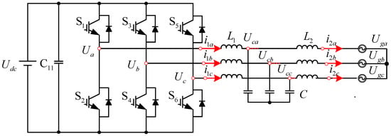
Figure 1.
Topology of LCL grid-tied inverter.
Figure 1 illustrates the mathematical model of the grid-connected three-phase LCL inverter as in [17]:
By sorting out (1) and performing a Laplace transform, the transfer functions of currents on the inverter side and the grid side , and inverter output voltage , are obtained:
The amplitude–frequency characteristic curves of Equations (2) and (3) are shown in Figure 2, and the parameters of the amplitude–frequency characteristic curves are shown in Table 1. Clearly, a system with an LCL filter is a third-order system, and the frequency response at the resonant frequency has resonance peaks, which can easily cause the system to be unstable. Therefore, to ensure system stability, a more comprehensive design of the LCL filter’s parameters and control approach is necessary.
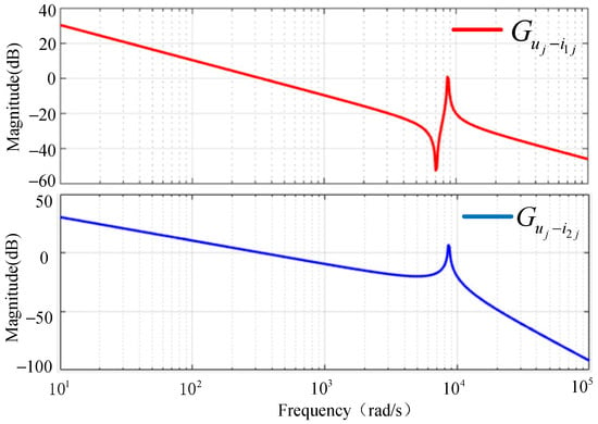
Figure 2.
Amplitude frequency characteristic curves of , .

Table 1.
Experimental parameters.
2.2. Analysis of Principle of Conventional FOSMC
The traditional FOSMC method is to directly design the LCL grid-connected inverter as a third-order system. By setting the reference value , the grid current is directly controlled. The traditional FOSMC needs to require the first derivative, second derivative, and third derivative of the grid-side current. Combined with Equation (1), multiple derivatives of the grid current can be obtained:
The design process for traditional FOSMC in LCL grid-connected inverters includes the following steps:
Firstly, FOSMC aims to track the grid current reference value , and the difference between the grid current reference and the actual grid current is defined as , and the error is continuously derived three times. The error of the grid-side current of the , , and LCL inverters is as follows:
The fractional term is incorporated into the sliding surface, allowing the design of the fractional sliding surface as
where is the order of the calculus operator; , , and represent the weights assigned to each state in the sliding surface, with being a scalar constrained by . By derivation of (6), we can obtain:
To maintain the system on the sliding surface and achieve a steady state, the approach rate is set as
Among them, is the parameter of the reaching law, satisfying . It is ensured that the system state reaches and remains on the sliding surface, enabling a gradual approach to the equilibrium point.
Combined with (4), (7), and (8), the control input of the LCL inverter using FOSMC is obtained:
It can be seen from (9) that the input of the controller is complicated. The obtained LCL modulation signal contains the first derivative term of the measurement signal , the second derivative term of , and the third derivative term of . The calculation process is cumbersome, and it contains multiple differentials of the measured variables, which easily makes the controlled system lose stability, and there is a problem of asymptotic stability over infinite time.
3. Design and Analysis of Improved Control Strategy
3.1. Important Definitions and Lemmas
Definition 1
([26,27]). Fractional calculus is usually defined in three different ways: the Caputo type, the Riemann–Liouville type, and the Grunwald–Letnikov type. Since the definition of initial conditions and the initial conditions of Caputo-type fractional calculus are consistent with those of integer-order calculus, in recent years, it has seen extensive application.
Definition: f(t) is a continuous integrable function, and its Caputo-type fractional calculus is defined as below:
where is the smallest integer not less than ; is the gamma function; and represents the differential in the traditional sense. can be any real number, , represents a fractional differential; , which represents the fractional integral on the interval . The fractional differential is transformed into an integral operation of its characteristic form, so it has a certain memory effect.
Lemma 1
([28,29]). Consider as a smooth function where . Provided that the subsequent inequality is satisfied,
where , , , , and are positive real numbers. The system described by Equation (10) will reach the stable region within a fixed time, with the upper bound of this time being independent of the initial state. The upper bound is given by
3.2. Design and Analysis of WACC
The WACC belongs to the active damping control strategy. By computing the weighted average of the inverter output current and the grid current , the virtual grid current is obtained, and the goal of tracking the grid current reference value is achieved. Let , , and , then the value of can be expressed as
Among them, is the weighted average current; . , are the weight coefficients of and , respectively, and is a constant ranging from 0 to 1. When , the third-order system of Equation (14) can be reduced to the first-order system of Equation (15):
When implementing WACC for the LCL inverter, Figure 3 is the amplitude–frequency characteristic curve of the transfer function of Equations (2), (3), and (15), and the parameters of the transfer function are shown in Table 1. This shows that the system is reduced to first-order, effectively suppressing resonance.
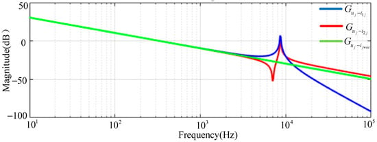
Figure 3.
This amplitude–frequency characteristic curves.
After order reduction, the mathematical model of the system is as follows:
3.3. Design of FTDO
During grid-connected operation, the filter inductances and are easily influenced by temperature, humidity, and other factors. Filter inductors and will affect the accuracy of , which will affect the stable operation of the inverter. Since the size changes of and are bounded, it is assumed that the change in impedance after the weighted current is due to the change in and , and there is an upper bound of . At this time, in the equivalent first-order system, the filter inductance is
Assuming that the disturbance caused by the change in and to is , the weighted average current containing the parameter disturbance term is
By substituting Equation (18) into Equation (16) and simplifying it, the mathematical model of the system considering filtering parameters is obtained:
Here, is the influence of parameter change on the weighted current derivative. Since the parameter variation is bounded, disturbance is bounded. The sum of the perturbations and is regarded as the total perturbation, and the total perturbation is bounded. Combined with Equation (19), the corresponding system’s state Equation is summarized as follows:
Here, , , and .
In order to quickly estimate the disturbance caused by the filter parameter perturbation in a fixed time, the FTDO is designed to estimate the disturbance term in (20). The design steps of the FTDO are as follows:
Firstly, the auxiliary variable is introduced, then Equation (20) can be rewritten as
Among these variables, is a normal number. Auxiliary variables are introduced:
The observer estimation error is defined as , and further:
Define and as the estimation and observation errors of , respectively, which can be
Here, ; is the sign function.
Inspired by the literature [28,30], the fixed design observer is designed as follows:
where , , , , , and .
The fixed-time observer is designed as Equation (25), and the estimation error of the total disturbance will converge to zero within a fixed time .
Proof 1.
Select the Lyapunov function as follows:
Now let , , and , and, with the derivation of , obtain the following:
Based on Lemma 1, when , the observation error will converge to 0, and can be calculated as follows:
The size of is determined by , , , and .
According to Equation (23), the estimation error of the disturbance is :
Therefore, the FTDO can estimate the unknown disturbance within a fixed time , and the estimation error converges to zero. When ,
□
3.4. Design of FTFOSMC
The design steps for the proposed FTFOSMC are outlined below:
Firstly, the grid current reference is set to , and the error between the virtual grid current and reference grid currents is defined as
The error is derived and (20) is simplified to obtain
Then, using the characteristics of fractional calculus, specifically how the energy transfer is slow and can effectively alleviate the chattering, by introducing the fractional calculus operator in the sliding mode control, the fractional fixed-time nonsingular terminal sliding mode surface is selected as follows:
Here, is the fractional order, and are positive numbers, , and .
From Equation (33), the derivative of is derived as follows:
To ensure the system state quickly reaches the sliding mode surface in a fixed time, the designed fixed-time reaching law is as follows:
Among these, and are normal numbers. After the disturbance is estimated by the FTDO, the disturbance is estimated and compensated for in the fixed-time sliding mode controller. Combined with (30), (34), and (35), the modulation signal input of the inverter can be obtained. The control input is as follows:
Through the comparison of three aspects, it can be proved that the proposed control strategy can reduce the amount of calculation. First of all, through the analysis of the required control information of the traditional FOSMC and the proposed FTFOSMC, the traditional FOSMC needs to measure the capacitor voltage, the grid-side current, and the grid voltage, while the FTFOSMC needs to measure the inverter-side current, the grid-side current, and the grid voltage. The amount of information required by the two is the same; secondly, in terms of computational complexity, the traditional FOSMC needs to obtain the third derivative of the grid current, which needs to be solved by simultaneous equations many times. However, FTFOSMC indirectly controls the current of WACC, and its system equation has become first-order, which does not need to be solved, greatly simplifying the computational complexity. Finally, by directly comparing the control input of the inverter as in Equations (9) and (36), it can be seen that the control input signal of the inverter obtained by the proposed control strategy is simpler. The derivation link only has one derivation of the reference current, and does not contain the derivation link of the measurement variable, which avoids the multiple differentiation of the measurement, and the proposed control strategy can also suppress the influence of the change in the filter inductance parameters and improve the anti-interference ability of the proposed control strategy.
3.5. Analysis of Fixed-Time Stability
Proof 2.
The approach motion converges from the initial point to the sliding surface in a fixed time.
The following positive definite Lyapunov function is set:
The derivation of is as follows:
Now let , , and ; for the derivation of , one obtains
Based on Lemma 1, the tracking sliding surface error can be stabilized within a small vicinity of within a fixed time , independent of initial conditions; the maximum stabilization time is as follows:
The size of is determined by , , , and . □
Proof 3.
After reaching the sliding mode surface, the tracking error of the grid-side current can move along the sliding mode surface to a tiny region around the equilibrium point within a fixed time . At this time, , and according to Equation (33), the following is obtained:
The Lyapunov function is written for the process from the sliding surface to the stable equilibrium point; the following positive definite Lyapunov function is set:
Now let , , and ; for the derivation of , one obtains the following:
Based on Lemma 1, the tracking current error stabilizes near the origin within a fixed time , irrespective of the initial conditions. The maximum stabilization time is as follows:
The size of is determined by , , , and .
In summary, the system stabilizes within a fixed time , with the upper limit for the entire grid-connected inverter system being . In order to make stable within 0.01 s, , , and can adjust their corresponding four parameters to determine their upper limits, so that the upper limit of the stability time corresponding to each segment is within 0.003 s. □
3.6. Overview of the Control Block Diagram
Figure 4 illustrates the overall structure of the proposed control strategy. As illustrated in Figure 4, after applying WACC, is derived from the currents on the grid-connected inverter side and the grid side. The difference between the current after the WACC and the reference current can be used to construct the fractional-order sliding mode surface. Through the FTDO, the estimated value of the disturbance caused by the filter parameter perturbation to the system can be obtained, which is compensated in the control input and improves the robustness of the system. Then, the FTFOSMC is employed for the fast tracking of the grid-connected current in a fixed time, enhancing the inverter’s dynamic performance.
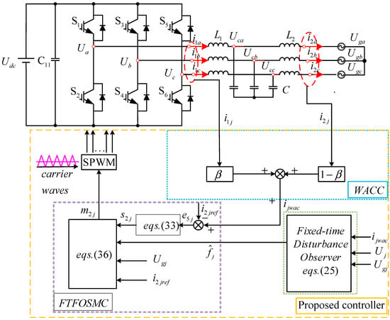
Figure 4.
A diagram of the proposed control strategy.
4. Simulation and Experimental Results
Firstly, to validate the proposed control strategy, simulations of the traditional FOSMC strategy and the new control strategy for the LCL inverter were conducted and compared in MATLAB R2022b/Simulink. Then, in order to further confirm the effectiveness of the proposed strategy, experimental verification was conducted using the dsPACE semi-physical simulation platform.
Table 1 provides the detailed experimental parameters. Based on the prior theoretical analysis, the controller’s constant values are as follows: ; ; , ; ; ; ; ; ; ; ; ; ; ; ; ; and .
4.1. Simulation Verification
(1) Steady-state analysis: To confirm the steady-state tracking performance of the suggested controller, a 10 A grid reference current was employed. Figure 5 compares the simulation results of the traditional FOSMC control and the proposed control strategy. Through comparison, it is evident that both the traditional FOSMC and the suggested control strategy can precisely track the reference grid current. The traditional FOSMC results in a grid-connected current THD of 3.03%, while the proposed control strategy achieves a THD of 1.33%. The control approach outlined in this paper exhibits superior steady-state performance.
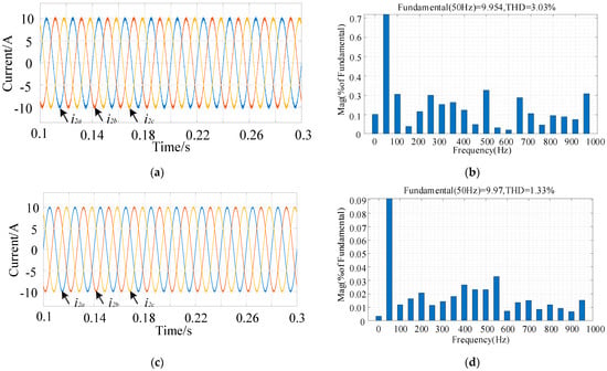
Figure 5.
The simulation results of the grid current in steady state: (a) the traditional controller; (b) the traditional controller’s THD; (c) the proposed controller; (d) the proposed controller’s THD.
(2) Robustness analysis under mismatched filter parameters: Figure 6 depicts the simulation results, comparing the traditional FOSMC to the new control strategy under parameter disturbances in the three-phase LCL grid-tied inverter. After t = 0.2 s, the inductance of both the inverter side and the grid side decreases by 10%. Figure 6 shows that, using the traditional FOSMC strategy, the THD of the waveform increases by 1.12% after the grid-connected current is t = 0.2 s; with the proposed improved control method, the waveform’s THD increases by 0.16%; and the waveform remains smooth after t = 0.2 s, which is affected by small filter parameter changes and shows high robustness.

Figure 6.
The simulation results of the grid current with parameter mismatch: (a) the traditional controller; (b) the proposed controller.
(3) Reference current rises: Figure 7 illustrates the peak reference value of the grid current in the three-phase LCL inverter jumping from 10 A to 15 A at 0.2 s. Simulation results compare the traditional FOSMC with the improved sliding mode control strategy. Figure 7 shows that the current overshoot of the three-phase inverter using the traditional FOSMC is 3A, and the response time is 0.02 s. With the suggested control approach, the three-phase inverter can quickly track the grid current’s peak reference value, demonstrating good dynamic performance.

Figure 7.
The simulation results of the current command changing the grid current: (a) the traditional controller; (b) the proposed controller.
(4) Reference current drop: Figure 8 shows that the reference value of the grid-connected current of the three-phase LCL grid-connected inverter is temporarily reduced from 10A to 5A at t = 0.02 s. The simulation results of the traditional FOSMC are compared with the improved sliding mode control strategy proposed in this paper. It can be seen from Figure 6 that under the traditional FOSMC, the response time of the three-phase inverter is 0.015 s, and it has a large overshoot. Under the proposed control strategy, the grid current has only slight fluctuations, quickly tracking the peak reference value of the grid current and having a better dynamic performance.

Figure 8.
The simulation results of the current command changing the grid current: (a) the traditional controller; (b) the proposed controller.
(5) Grid voltage change: When t = 0.1 s, the grid voltage decreases by 50%. Compared with Figure 9 and Figure 10, the traditional FOSMC strategy exhibits a 3A overshoot and returns to a steady state after 0.02 s. The proposed control strategy has a strong dynamic anti-interference ability. After the grid voltage changes, there is only an overshoot of 0.5A and it returns to the steady state quickly, which is influenced by the small grid voltage change.

Figure 9.
Simulation results under traditional FOSMC control: (a) grid voltage change; (b) grid current.

Figure 10.
Simulation results under the proposed controller: (a) grid voltage change; (b) grid current.
4.2. Experimental Verification
To further validate the proposed control strategy’s effectiveness, experimental verification is carried out on the dsPACE semi-physical simulation platform. Figure 11 presents the experimental platform, with parameters that are completely consistent with those used in the simulations. The experiment primarily validates the steady-state and dynamic characteristics of both the traditional FOSMC and the proposed control strategy.
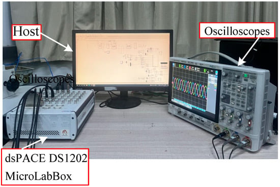
Figure 11.
dsPACE semi-physical simulation platform.
(1) Steady-state verification: Figure 12 shows the steady-state current waveforms for the traditional FOSMC and the proposed control strategy. With the proposed control strategy, the system’s grid-connected current exhibits a small THD, the current waveform is smooth, and the system runs stably.
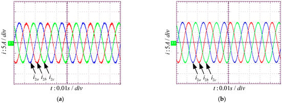
Figure 12.
The experimental results of the grid current under steady-state conditions: (a) the traditional controller; (b) the proposed controller.
(2) Dynamic verification: Figure 13 verifies the dynamic behavior of both the traditional FOSMC and the proposed strategy. When the grid reference current shifts from 10A to 15A, the proposed control strategy responds more quickly to reference current changes than the traditional FOSMC method, allowing the system to rapidly achieve a new stable state and exhibit better dynamic performance.
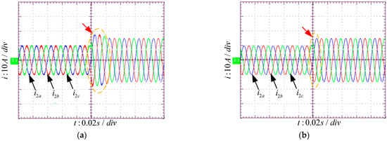
Figure 13.
The experimental results of the grid current under dynamic conditions: (a) the traditional controller; (b) the proposed controller.
5. Conclusions
This paper focuses on the LCL inverter. To address the high computational load and slow convergence of the traditional FOSMC strategy for LCL grid-connected inverters, a fixed-time robust fractional-order sliding mode controller based on weighted current control is proposed. The contribution of this method is that, firstly, the controller design is simplified from the third-order system to the first-order system by WACC, which reduces the computational complexity. When using WACC, it is necessary to accurately know the inductance parameters of the filter. If the inductance values of the inverter side and the grid side are not accurate, the calculated weighting coefficient cannot obtain the optimal value; moreover, FTDO can quickly estimate and compensate the system interference, and enhance the anti-interference ability of the system. At the same time, the FTFOSMC strategy is applied to output the control modulation signal, which improves the dynamic performance of the system. The simulation and experimental results show that the control strategy has good anti-interference ability when the filter parameters change. When the reference current or grid voltage changes, the three-phase grid-connected inverter can quickly track the new reference value and show better dynamic performance.
The current research only focuses on a single grid-connected inverter, and future research can consider extending FTDO and FTFOSMC to the scenario of parallel inverters. In the case of multiple inverters in parallel, there may be coupling between the output of each inverter and the adjacent inverters, which affects the stability of the overall system. In order to solve this problem, FTDO can be used to quickly detect and compensate the cross-interference between parallel inverters, and FTFOSMC is used to design a global coordinated control strategy to ensure that parallel inverters can maintain efficient and stable operation under various operating conditions. The expansion of this method may help to improve the overall performance and reliability of the inverter parallel system, which is a main part of my future research.
Author Contributions
Conceptualization, W.S. and G.H.; software, W.S. and G.H.; validation, W.S. and G.H.; formal analysis, W.S. and G.H.; investigation, Y.D.; resources, G.H.; data curation, W.S.; writing—original draft preparation, W.S. and G.H.; writing—review and editing, W.S. and G.H.; visualization, Z.Z.; supervision, Y.D.; project administration, Y.D.; funding acquisition, Y.D. All authors have read and agreed to the published version of the manuscript.
Funding
This research was funded by Henan Province, China, grant number 24210230202. The project name is Research and Application of Key Technology of Active Disturbance Rejection Control for Shunt Active Power Filter. The project host is Dong Yanfei.
Data Availability Statement
The data presented in this research study are available in this article.
Conflicts of Interest
The authors declare no conflicts of interest.
References
- Ma, Z.; Zhang, H.; Zhao, H.; Wang, M.; Sun, Y.; Sun, K. New mission and new challenge of power distribution and utilization system under dual carbon target. Zhongguo Dianji Gongcheng Xuebao/Proc. Chin. Soc. Electr. Eng. 2022, 42, 6931–6945. [Google Scholar]
- Li, B.; Chen, M.; Zhong, H.; Ma, Z.; Liu, D.; He, G. Summary of long-term planning of new power system with high proportion of renewable energy. Chin. J. Electr. Eng. 2023, 43, 555–581. [Google Scholar]
- Zhang, R.; Zhang, C.; Xing, X.; Chen, Z.; Liu, X. Modeling and Control Method to Suppress Common-Mode Resonance Circulating Current for High-Power Parallel Three-Level Inverters System with Improved LCL Filter. IEEE Trans. Ind. Electron. 2023, 70, 2484–2496. [Google Scholar] [CrossRef]
- Hong, L.; Tang, R.; Jiang, Q.; Xie, X.; Zhu, Y. Admittance-Based Stability Analysis of LCL-Type Grid-Connected Inverter Considering AC-Side and AC-DC Frequency Coupling Effects. IEEE Trans. Power Deliv. 2024, 39, 1351–1363. [Google Scholar] [CrossRef]
- Kouchaki, A.; Nymand, M. Analytical Design of Passive LCL Filter for Three-Phase Two-Level Power Factor Correction Rectifiers. IEEE Trans. Power Electron. 2018, 33, 3012–3022. [Google Scholar] [CrossRef]
- Guan, Y.; Wang, Y.; Xie, Y.; Liang, Y.; Lin, A.; Wang, X. The Dual-Current Control Strategy of Grid-Connected Inverter with LCL Filter. IEEE Trans. Power Electron. 2019, 34, 5940–5952. [Google Scholar] [CrossRef]
- Zhuang, C.; Ye, Y.; Zhao, Q.; Wang, J.; Zhang, H. Analysis and improvement of LCL grid-connected inverter control strategy based on split capacitor method. J. Electr. Technol. 2015, 30, 85–93. [Google Scholar]
- Zhu, K.; Sun, P.; Wang, L.; Zhou, L.; Xue, T.; Du, X.; Li, Z. High robustness weighted average current control strategy for LCL-type grid-connected inverters under weak grid. Chin. J. Electr. Eng. 2020, 40, 3592–3602. [Google Scholar]
- Nam, N.N.; Nguyen, N.D.; Yoon, C.; Choi, M.; Lee, Y.I. Voltage Sensorless Model Predictive Control for a Grid-Connected Inverter With LCL Filter. IEEE Trans. Ind. Electron. 2022, 69, 740–751. [Google Scholar] [CrossRef]
- Panda, S.K.; Subudhi, B. An Extended State Observer Based Adaptive Backstepping Controller for Microgrid. IEEE Trans. Smart Grid 2024, 15, 171–178. [Google Scholar] [CrossRef]
- Kumar, M.; Sen, S.; Kumar, S.; Samantaray, J. An Adaptive Fuzzy Controller-Based Distributed Voltage Control Strategy for a Remote Microgrid System with Solar Energy and Battery Support. IEEE Trans. Ind. Appl. 2024, 60, 4870–4887. [Google Scholar] [CrossRef]
- Shen, X.; Liu, J.; Alcaide, A.M.; Yin, Y.; Leon, J.I.; Vazquez, S.; Wu, L.; Franquelo, L.G. Adaptive Second-Order Sliding Mode Control for Grid-Connected NPC Converters With Enhanced Disturbance Rejection. IEEE Trans. Power Electron. 2022, 37, 206–220. [Google Scholar] [CrossRef]
- Yin, Y.; Vazquez, S.; Marquez, A.; Liu, J.; Leon, J.I.; Wu, L.; Franquelo, L.G. Observer-Based Sliding-Mode Control for Grid-Connected Power Converters Under Unbalanced Grid Conditions. IEEE Trans. Ind. Electron. 2022, 69, 517–527. [Google Scholar] [CrossRef]
- Li, Z.; Cheng, Z.; Li, S.; Si, J.; Gao, J.; Dong, W.; Das, H.S. Virtual Synchronous Generator and SMC-Based Cascaded Control for Voltage-Source Grid-Supporting Inverters. IEEE J. Emerg. Sel. Top. Power Electron. 2022, 10, 2722–2736. [Google Scholar] [CrossRef]
- Tian, L.; Yang, X. Sliding mode control strategy applied to quasi-Z-source inverter in photovoltaic grid-connected system. J. Sol. Energy 2023, 44, 443–449. [Google Scholar]
- Yang, T.S.; Zhong, S.; Yu, S. Robust fractional-order sliding mode control design for grid-connected photovoltaic inverters. Control Theory Appl. 2020, 37, 374–386. [Google Scholar]
- Long, B.; Lu, P.; Zhan, D.; Lu, X.; Rodríguez, J.; Guerrero, J.M.; Chong, K. Adaptive fuzzy fractional-order sliding-mode control of LCL-interfaced grid-connected converter with reduced-order. ISA Trans. 2023, 132, 557–572. [Google Scholar] [CrossRef]
- Wu, W.; Qiu, L.; Liu, X.; Ma, J.; Rodriguez, J.; Fang, Y. Dynamic-Linearization-Based Predictive Control of a Voltage-Source Inverter. IEEE Trans. Ind. Electron. 2024, 71, 3275–3284. [Google Scholar] [CrossRef]
- Long, B.; Lu, P.J.; Chong, K.T.; Rodriguez, J.; Guerrero, J.M. Robust Fuzzy-Fractional-Order Nonsingular Terminal Sliding-Mode Control of LCL-Type Grid-Connected Converters. IEEE Trans. Ind. Electron. 2022, 69, 5854–5866. [Google Scholar] [CrossRef]
- Sou, W.-K.; Chan, P.-I.; Gong, C.; Lam, C.-S. Finite-Set Hybrid Model Predictive Control for Thyristor-Controlled LC-Coupling Hybrid Active Power Filter. IEEE Trans. Ind. Electron. 2024, 71, 9994–10006. [Google Scholar] [CrossRef]
- Long, B.; Mao, W.; Lu, P.; Rodriguez, J.; Guerrero, J.M.; Chong, K.T.; Teng, Y. Passivity Fractional-Order Sliding-Mode Control of Grid-Connected Converter with LCL Filter. IEEE Trans. Power Electron. 2023, 38, 6969–6982. [Google Scholar] [CrossRef]
- He, G.; Zhou, Z.; Zhang, G.; Li, G. Fixed-time fuzzy backstepping control strategy for island photovoltaic parallel inverter system. Power Syst. Prot. Control 2023, 51, 147–156. [Google Scholar]
- Hosseinabadi, P.A.; Mekhilef, S.; Pota, H.R.; Kermadi, M. Chattering-Free Fixed-Time Robust Sliding Mode Controller for Grid-Connected Inverters Under Parameter Variations. IEEE J. Emerg. Sel. Top. Power Electron. 2024, 12, 579–592. [Google Scholar] [CrossRef]
- Cai, Y.; He, Y.; Zhou, H.; Liu, J. Active-Damping Disturbance-Rejection Control Strategy of LCL Grid-Connected Inverter Based on Inverter-Side-Current Feedback. IEEE J. Emerg. Sel. Top. Power Electron. 2021, 9, 7183–7198. [Google Scholar] [CrossRef]
- Rahman, M.M.; Biswas, S.P.; Islam, M.R.; Rahman, M.A.; Muttaqi, K.M. An Advanced Nonlinear Controller for the LCL-Type Three-Phase Grid-Connected Solar Photovoltaic System with a DC–DC Converter. IEEE Syst. J. 2022, 16, 3203–3214. [Google Scholar] [CrossRef]
- Fei, J.; Wang, Z.; Pan, Q. Self-Constructing Fuzzy Neural Fractional-Order Sliding Mode Control of Active Power Filter. IEEE Trans. Neural Netw. Learn. Syst. 2023, 34, 10600–10611. [Google Scholar] [CrossRef]
- Fei, J.; Wang, Z.; Fang, Y. Self-Evolving Recurrent Chebyshev Fuzzy Neural Sliding Mode Control for Active Power Filter. IEEE Trans. Ind. Inform. 2023, 19, 2729–2739. [Google Scholar] [CrossRef]
- Liu, Y.; Li, H.; Lu, R.; Zuo, Z.; Li, X. An Overview of Finite/Fixed-Time Control and Its Application in Engineering Systems. IEEE/CAA J. Autom. Sin. 2022, 9, 2106–2120. [Google Scholar] [CrossRef]
- Jia, T.; Pan, Y.; Liang, H.; Lam, H.-K. Event-Based Adaptive Fixed-Time Fuzzy Control for Active Vehicle Suspension Systems With Time-Varying Displacement Constraint. IEEE Trans. Fuzzy Syst. 2022, 30, 2813–2821. [Google Scholar] [CrossRef]
- Lin, X.; Wu, C.; Yao, W.; Liu, Z.; Shen, X.; Xu, R.; Sun, G.; Liu, J. Observer-Based Fixed-Time Control for Permanent-Magnet Synchronous Motors With Parameter Uncertainties. IEEE Trans. Power Electron. 2023, 38, 4335–4344. [Google Scholar] [CrossRef]
Disclaimer/Publisher’s Note: The statements, opinions and data contained in all publications are solely those of the individual author(s) and contributor(s) and not of MDPI and/or the editor(s). MDPI and/or the editor(s) disclaim responsibility for any injury to people or property resulting from any ideas, methods, instructions or products referred to in the content. |
© 2024 by the authors. Licensee MDPI, Basel, Switzerland. This article is an open access article distributed under the terms and conditions of the Creative Commons Attribution (CC BY) license (https://creativecommons.org/licenses/by/4.0/).