Article

Energy and Economic Analysis of a New Combination Cascade Waste Heat Recovery System of a Waste-to-Energy Plant

1
School of Business, Guangxi University, Nanning 530004, China
2
School of Economics, Guangxi University, Nanning 530004, China
*
Author to whom correspondence should be addressed.
Energies 2024, 17(20), 5196; https://doi.org/10.3390/en17205196
Submission received: 15 September 2024 / Revised: 1 October 2024 / Accepted: 8 October 2024 / Published: 18 October 2024

Abstract

:
Waste incineration has become the main treatment method for urban household waste, and it can produce a large amount of electricity. The efficiency of waste incineration plants is reduced due to the large amount of waste heat carried away by the flue gas. Recycling and utilizing the waste heat from flue gas are important in improving the economic benefits of waste incineration, which is necessary for energy conservation and emission reduction. Based on the principle of cascade waste heat recovery from waste incineration flue gas whilst considering system safety and efficiency, this study proposed a new combination cascade waste heat recovery system consisting of a Rankine cycle, an organic Rankine cycle and a heat pump cycle. Thermodynamic and economic analyses of the combined system were conducted in detail. The results indicated that the energy efficiency of the combined system could reach up to 73%. The maximum net present value of the system was million USD 1.59 million, and the dynamic investment payback period was about 6.5 years. The isentropic efficiency of the combined system’s pumps and turbines had a significant impact on the system’s performance. A higher isentropic efficiency resulted in better system performance. The exergy analysis showed that the evaporator of the heat pump system had the highest irreversible loss.

1. Introduction

The development of the social economy has led to an increasing amount of urban household waste [1]. How to properly handle this waste has become a common problem faced by countries around the world. Traditional landfill has become unsustainable due to the scarcity of land resources. Waste incineration can not only generate electricity but also eliminate harmful gases. Waste incineration has become the mainstream method for treating household waste, and various regions around the world advocate for waste incineration [2]. There are some prominent issues with waste incineration, such as the disposal of fly ash from waste incineration and the utilization of waste heat from high-temperature flue gas. A large amount of research has shown that fly ash is a good material that can be used for various purposes [3,4]. The high-temperature flue gas generated by waste incineration carries enormous heat. The efficiency and economic performance of waste incineration power plants will be reduced if this heat cannot be effectively recycled.
The recovery of waste heat from flue gas after waste incineration has become a research hotspot in the field. Kim et al. [5] investigated the performance of recovering waste heat from flue gas and removing dust with an enthalpy wheel. The results showed that the system’s thermal efficiency reached a maximum of 61%, with an average dust removal efficiency of 79.6%. Chen et al. [6] studied the performance of absorption heat pumps in recovering waste heat from flue gas. The system designed in winter increased the power output by 1.21MW compared to the original system, and the energy efficiency of the waste incineration plant with waste heat recovery was improved.

2. Literature Review

In research on waste heat recovery from waste incineration flue gas, utilizing various efficient circulation methods to recover the flue gas for electricity and heat production is a promising research direction. Rankine cycles (RCs) are widely used for waste heat recovery from high-temperature flue gas due to their simple structure and high stability. Wang et al. [7] investigated the matching mechanism between the heat-source temperature and working fluid in RCs. The results indicated that after the temperature matching, the overall efficiency of the system was improved, and carbon emissions were also reduced. Guerron et al. [8] designed an RC system to recover waste heat from industrial processes in power plants. The experimental results showed that the efficiency of the RC system was 3.52%, with an exergy efficiency of 5.45%.
Organic working fluids are used as working fluids for RCs due to their adaptability to high temperatures. Cycles with organic working fluids are also known as organic Rankine cycles (ORCs). ORC systems are common systems in the field of waste heat recovery, as they have higher thermal efficiency and stability. Biancini’s research results indicated that ORC systems were more flexible compared to other heat recovery systems [9]. Compared to supercritical cycles, ORCs had more advantages in the field of low-temperature waste heat recovery [10]. Lebedevas and Č Epitis studied the potential of ORC systems in recovering waste heat from secondary heat sources. The ORC systems improved the energy efficiency of the main system [11].
In addition, a reasonable combination of ORC systems and other heat recovery systems can effectively improve system efficiency. Mirzaei et al. [12] studied the performance of a dual organic Rankine cycle for recovering waste heat from flue gas. The system efficiency reached 79%, and waste heat recovery reduced the system’s fuel consumption. Besevli et al. [13] studied the performance of a combined ORC for recovering waste heat in order to produce electricity. The steam Rankine cycle had more advantages in terms of recovering high-temperature flue gas waste heat and could maximize the power output. Lyu et al. [14] conducted a detailed thermodynamic analysis with an ORC system to recover waste heat from ship flue gas. The evaporator and condenser of the ORC system had high irreversible losses. The ORC system with cyclohexane as the working fluid had a higher power output. Liu et al. [15] experimentally tested a novel splitting ORC system to avoid the imbalance of a simple ORC when the waste heat was a dual heat source. The internal combustion engine efficiency and thermal efficiency increased by 9.6% and 27.9%, respectively. Wang et al. [16] proposed a combined ORC system that consisted of a transcritical RC system and a subcritical ORC system to recover the waste heat from a VI emission standard engine. The combined system improved the power output of the engine by 71.29 kW under the rated operating conditions. Ravindran et al. [17] investigated the performance of an ORC system combined with a high-temperature heat pump to recover industrial waste heat under 100 degrees in an experiment. The largest net power output was 512.4 kW in the ORC mode, with a total cycle efficiency of 3.01%. Feng et al. [18] investigated the thermal economic performance of an ORC system in terms of waste heat recovery of low-temperature flue gas. The exergy efficiency was maximum when the organic fluid was butane, with a heat recovery rate of 64.18%. Zhang et al. [19] proposed a new combined ORC system based on a regenerator for the waste heat recovery of a rotorcraft power plant application. The highly effective regenerator could increase the fuel economy, and the ORC system improved the power output of the engine. Zhou et al. [20] carried out a study of an ORC system with multiple functions for waste heat recovery from data centers. An increment in the temperature difference between the evaporator and condenser improved the efficiency of the ORC.
RC and ORC systems have their own advantages in different temperature ranges. Composite systems of RCs and ORCs were more efficient in situations with multiple requirements [21]. A heat pump (HP) system was also applied to flue gas waste heat recovery due to the advantages of efficient recovery of low-temperature heat sources, especially when hot water was needed. Zhang et al. [22] conducted an experimental study on the performance of a HP system in recovering low-temperature flue gas heat for heating. The HP system recovered a large amount of flue gas heat, reduced the flue gas temperature and increased the heating heat. Jang et al. [23] studied an HP system which recovered low-temperature waste heat from data centers and heated the buildings in winter. The HP system reduced heating energy consumption by 48.2% and carbon dioxide emissions by 28.7%. Ghaderi et al. [24] studied the performance of HP combination systems for recovering ventilation waste heat, which can save 57% of primary energy with an investment payback period of 9.5 years. Zhou et al. [25] studied the performance of an HP system in recovering industrial waste heat for heating, with a system coefficient of performance (COP) of 4.5. Ma et al. [26] investigated the effect of different working mediums on a high-temperature HP system for waste heat recovery. The MC-1 was the optimal medium with a COP of 5.05. Vannoni et al. [27] carried out a techno-economic optimization analysis for a high-temperature HP system with R600a. The evaporator had great influence on the system efficiency and economy. The annual energy consumption was affected by retail prices. Therefore, the running mode and performance of waste heat recovery with a high-temperature HP system varied from country to country.
In this study, a new combined waste heat recovery system was proposed for the cascade waste heat recovery of flue gas from a waste incineration plant. The combination system performed better in the cascade utilization of waste heat. An RC was used to directly recover high-temperature waste heat from flue gas to maximize the recovery of waste heat. An ORC system used steam from the outlet of the RC system’s turbine as a secondary heat source to produce electricity. The HP system further recovered waste heat from flue gas, reduced flue gas temperature, achieved stepwise heat recovery from flue gas and increased heating heat. This study conducted thermodynamic analyses including energy analysis and exergy analysis. The systematic economic analysis was conducted based on the energy analysis to study the economic feasibility of the system. The results of this study are valuable for the recovery of waste heat from flue gas in waste incineration plants.

3. Description of New Combination Cascade Waste Heat Recovery System

Figure 1 presents the flowchart of the new combination cascade waste heat recovery system which achieves cascade heat recovery. The ORC used organic media, and it should not come into direct contact with the flue gas when recovering high-temperature flue gas waste heat. The top cycle with direct contact with flue gas was set as a steam RC in this study. The cycle flow was from state points 1 to 4, with T1 and P1 as the turbine and pump of the RC system. HE1 was the flue gas heat exchanger, and HE2 was the condenser of the RC system as well as the evaporator of the ORC system. The ORC system took steam from the outlet of the turbine of the RC system as the heat source and further recovered the rest of the heat to generate electricity. The cycle flow of the ORC system was from state points 5 to 8. HE3 was the condenser of the ORC system. P2 and T2 were the pump and turbine of the ORC system. All the work generated by the ORC system was transmitted to the compressor of the heat pump system. The heat pump system further absorbed the waste heat of flue gas to achieve the goal of cascade recovery and delivered hot water or heat to the outside through HE5. C was the compressor of the heat pump system. V was the throttle valve. HE4 and HE5 were the evaporator and condenser of the HP system. The circulation process of the heat pump system was from state points 9 to 11. The new combination cascade waste heat recovery system took a safety perspective based on the principle of temperature matching cascade utilization. It recovered the waste heat from the flue gas of waste incineration plants and produced electricity and heat, which conformed to the trend of carbon reduction with good environmental friendliness. The organic working fluid used in the ORC system was butane, which had a lower greenhouse effect potential with higher safety.
The parameter settings of the system are given in Table 1.

4. Mathematical Model of New Combination Cascade Waste Heat Recovery System

Energy analysis, thermal analysis and economic analysis were applied in this study. Some assumptions were proposed to simplify the model and save computational resources: (1) the system works in a stable state; (2) the pressure loss and mass loss of the system can be ignored; and (3) the ambient temperature and pressure are 298.15 K and 101.325 kPa, respectively.

4.1. Energy Explanation

The performance of system components obtained through exergy analysis could improve component design and optimization. Energy analysis is based on the first law of thermodynamics. The basic principles are the conservation of quality mass, as shown in Equation (1), and energy, as shown in Equation (2) [28].
m ˙ i = m ˙ o
Q ˙ + m ˙ i h i = W ˙ + m ˙ o h o
where i is the input and o represents the output. m ˙ is the mass flow rate, in kg/s. Q ˙ is the heat through the system boundary, in J. W ˙ is the power transfers through the system boundary. h is the enthalpy, in kJ/kg. The energy conservation calculation of heat exchangers is based on the pinch-point temperature difference method [29].
The control equations of each component in the system are listed in Table 2.
In Table 1, η is the isentropic efficiency, in %. c ˙ p is the specific heat at a constant pressure, in kJ/(kg·K). T is the temperature, in K.
The net power of the system can be calculated with Equation (3):
N e t   p o w e r = W ˙ T 1 + W ˙ T 2 W ˙ P 1 W ˙ P 2 W ˙ C
The system heat output is calculated using Equation (4):
H e a t   s u p p l y = m ˙ H P h 10 h 11
The energy efficiency of the entire system can be obtained with Equation (5):
E n e r g y   e f f i c i e n c y = N e t   p o w e r + H e a t   s u p p l y m ˙ g c ˙ p , g T 13 T 14

4.2. Exergy Anatomy

Exergy analysis is helpful to understand the transmission direction of useful work in a system to obtain the performance of each component. Generally, kinetic and potential exergy can be ignored. The expression for the exergy of each fluid state point is given in Equation (6) [30].
E ˙ s = h s h a T a s s s a
where E is the exergy value, in J. s is the fluid state point. a is the environmental state. The exergy loss of each component can be expressed with Equation (7):
I D = I i I o
where Ii and Io are the incoming and outgoing exergy of the components, in J. ID is the exergy loss of the component, in J. The exergy balance equations for each component of the composite system are given in Table 3.

4.3. Economic Analysis

Economic analysis was applied to evaluate the economic performance of the system. The system can achieve profitability, which has practical application potential and guiding significance. Net present value (NPV) is often used in economic analysis, which is an intuitive economic parameter [31]. Only systems with an NPV greater than 0 can be adopted. Dynamic investment payback period (DPP) is also an important parameter of the system, which represents the time to attain system investment payback. DPP and NPV are used together in economic analysis [32].
The calculation expressions for NPV and DPP are given in Equations (8) and (9):
N P V = n = 1 τ C in C out 1 + i d n
n = 1 D D P C in C out 1 + i d n = 0
where τ is the useful life. id is the discount rate. Cin and Cout are annual income and expenditure. In economic analysis, the most important is to calculate the cost of each component of the system [33,34], and the equations are listed in Table 4.

4.4. Model Validation

In this study, a simulation study was conducted with MATLAB 2020a, and REFPROP9.0 was used to obtain the physical properties’ parameters. The simulation and experimental data were compared to verify the model accuracy. The comparison values of the proposed system and that in the literature [35,36] are given in Table 5 under the same input condition. The RC and ORC systems have the same structure with different working fluids. Both systems were validated under the ORC design state. Compared with the data in the literature [35,36], the maximum errors of the ORC system and the HP system are 6.25% and 5.54% within the error range. The error between the simulation results and experimental data represents the unpredictable data fluctuation during the experimental process. The error between the simulation results and experimental data of the literature [35,36] is acceptable. The verification results indicate that the simulation has high accuracy.

5. Results and Discussion

Detailed analyses were conducted on some highly influential system parameters to obtain optimal performance. These parameters included the evaporation pressure of HE1, the evaporation temperature of HE4, the heating temperature T20, the condensation temperature of HE2, and the isentropic efficiency of the pumps and turbines.

5.1. HE1 Evaporation Pressure Effect

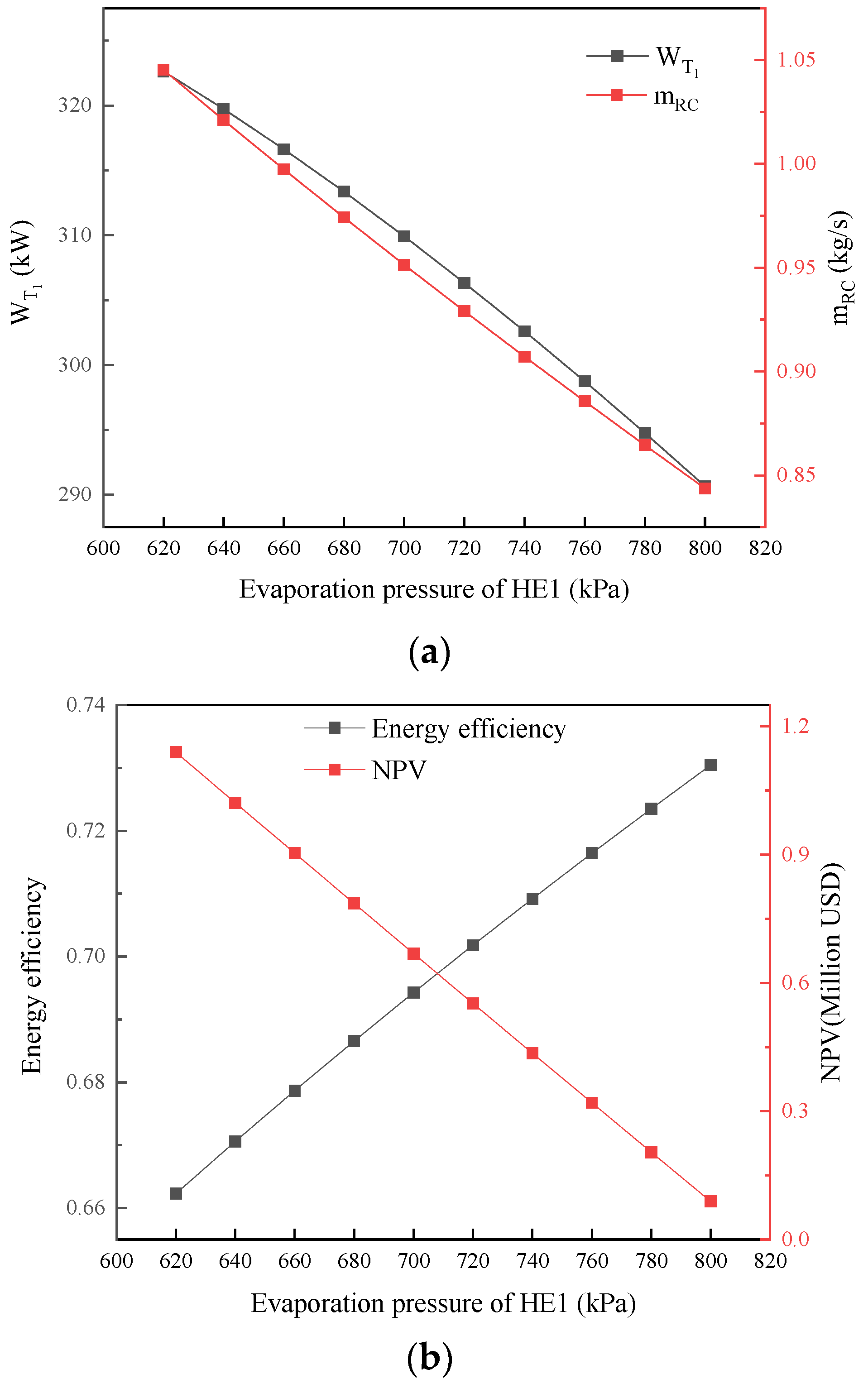
Figure 2 shows the variation in system performance with the HE1 evaporation pressure. The evaporation pressure range was from 620 kPa to 800 kPa. As shown in Figure 2a, the turbine power of the RC decreased from 323 kW to 290 kW with an increase in HE1 evaporation pressure. The evaporation pressure increased the evaporation temperature of HE1, which indirectly reduced the mass flow rate of the RC. The heat obtained by HE1 from the flue gas changed less when the narrow-point temperature difference was constant. The increase in evaporation temperature led to a reduction in the circulating mass flow rate. The decrease in the system output power resulted in a reduction in the net present value from million USD 1.05 to nearly million USD 0. The energy efficiency of the system increased from 0.66 to 0.73, as shown in Figure 2b. The increase in the evaporation pressure was beneficial for the system thermal efficiency but was detrimental to the output power and system economic performance. The exergy efficiency of the combined system increased with an increase in evaporation temperature. The temperature of streams 14 and 15 increased with the evaporation temperature increment, which led to an increase in exergy loss in HE4. The exergy efficiency could not reach the optimal value with the economic performance simultaneously.

5.2. HE4 Evaporation Temperature Impact

The impact of the HE4 evaporation temperature on system performance is presented in Figure 3. HE4 is the evaporator of the HP system, which is used to further recover waste heat from flue gas to achieve the goal of efficiency improvement. The evaporation temperature of HE4 had a significant impact on the HP system. The evaporation temperature increased from 319.15 K to 328.15 K. Both the mass flow rate and compressor power of the HP system decreased as the temperature increased, as shown in Figure 3a. The fluid absorbed heat in the HP system decreased with an increase in evaporation temperature under the same heat exchange rate, which caused a reduction in the HP mass flow rate. On the premise that the isentropic efficiency of the compressor remained unchanged, the compressed flow rate decreased while the temperature rise remained unchanged, which caused a reduction in the compressor power. The decrease in power also led to a reduction in the purchase cost of the compressor, as shown in Figure 3b. The NPV of the system increased with the evaporation temperature increase, from million USD −0.02 to million USD 1.59. The results indicated that a low evaporation temperature can also lead to a reduction in NPV to a negative value. The increase in the evaporation temperature within a reasonable range can improve the system economic performance. The reduction in system costs (especially the cost of the HP system compressors) was the main reason for the increment in system economic benefits. Under similar heat output conditions, system equipment investment reduction can effectively improve the system economic performance.

5.3. T20 Ascendancy

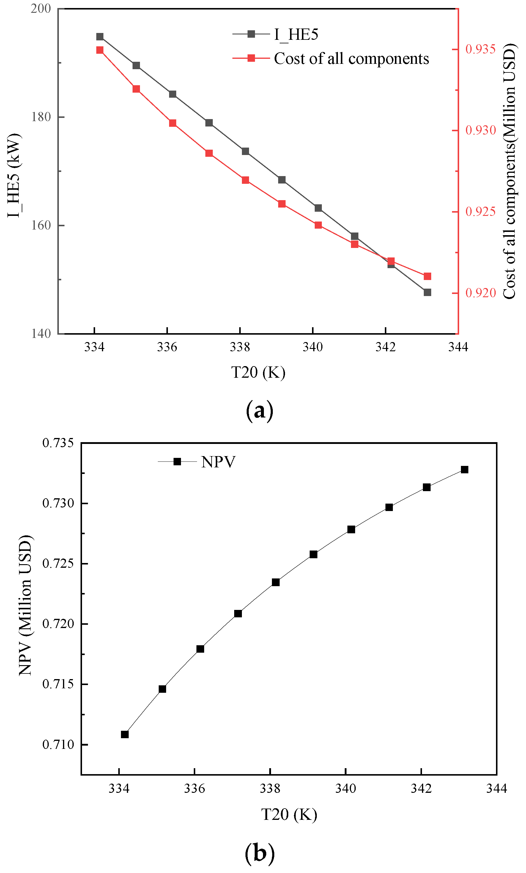
The impact of the heating temperature T20 on the system is shown in Figure 4. Owing to the fact that the heating temperature had no effect on the energy efficiency of the system, this study focused on the heating temperature impact on the HE5 exergy loss, system cost and economic efficiency (NPV). T20 increased from 334.15 K to 343.15 K. The exergy loss of the heat exchanger decreased as the heating temperature increased, as shown in Figure 4a. The fluid temperature at the outlet of the HP system compressor was relatively high. The increment in the heating temperature reduced the heat transfer temperature difference of HE5. The smaller the temperature difference of heat exchange, the smaller the heat transfer loss. The decrease in heat exchange losses caused a reduction in equipment costs, which led to a decrease in the overall purchase cost of the system. The economic efficiency (NPV) shown in Figure 4b increased slightly from million USD 0.71 to million USD 0.73. This indicated that the heating temperature was positively correlated with system performance and the heating temperature could be appropriately increased.

5.4. HE2 Condensation Temperature Influence

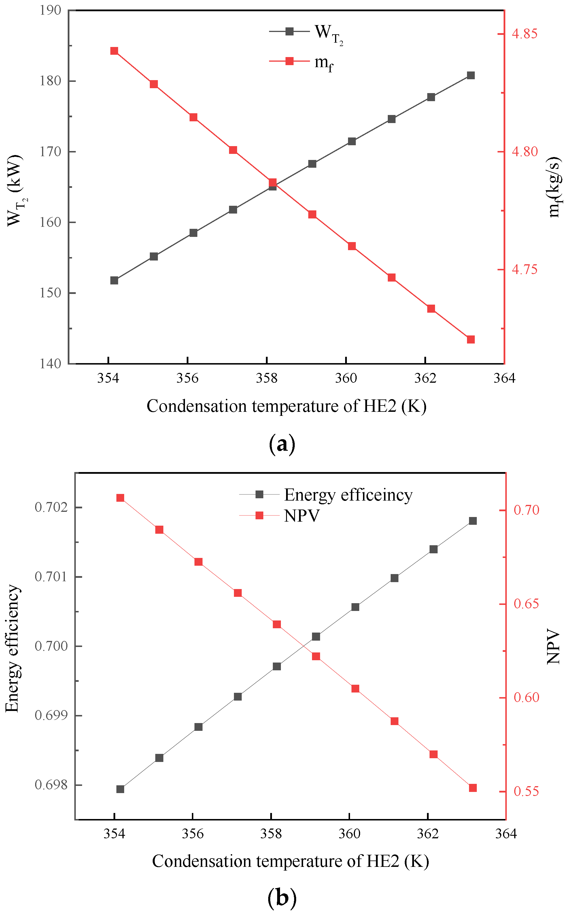
The impact of the HE2 condensation temperature on the system is shown in Figure 5. The condensation temperature of HE2 directly affected the evaporation temperature of the ORC, which was necessary to study the impact on the system. The condensation temperature of HE2 increased from 354.15 K to 363.15 K. The output power of the ORC system turbine increased from 151 kW to 180 kW, with an increase of 19%, as shown in Figure 5a. The condensation temperature increment of HE2 increased the temperature of the fluid at the inlet of the ORC system turbine, which led to an increase in the output power of the ORC system turbine.
The mass flow rate of the ORC system decreased with an increase in the HE2 cold energy temperature. The proportion of decrease was small, with a reduction of 2.5% from 4.84 kg/s to 4.72 kg/s. Although the fluid flow rate decreased, the increase in fluid temperature was more conducive to improving the system output power. The energy efficiency of the system increased with the increment in the HE2 condensation temperature, as shown in Figure 5b. However, the system NPV decreased due to an increase in condensation temperature. The increase in system output power was not enough to compensate for the reduction in economic benefits caused by the increment in equipment costs. Therefore, the condensation temperature of HE2 should be taken as a smaller value from an economic perspective.

5.5. Effect of Pump Isentropic Efficiency

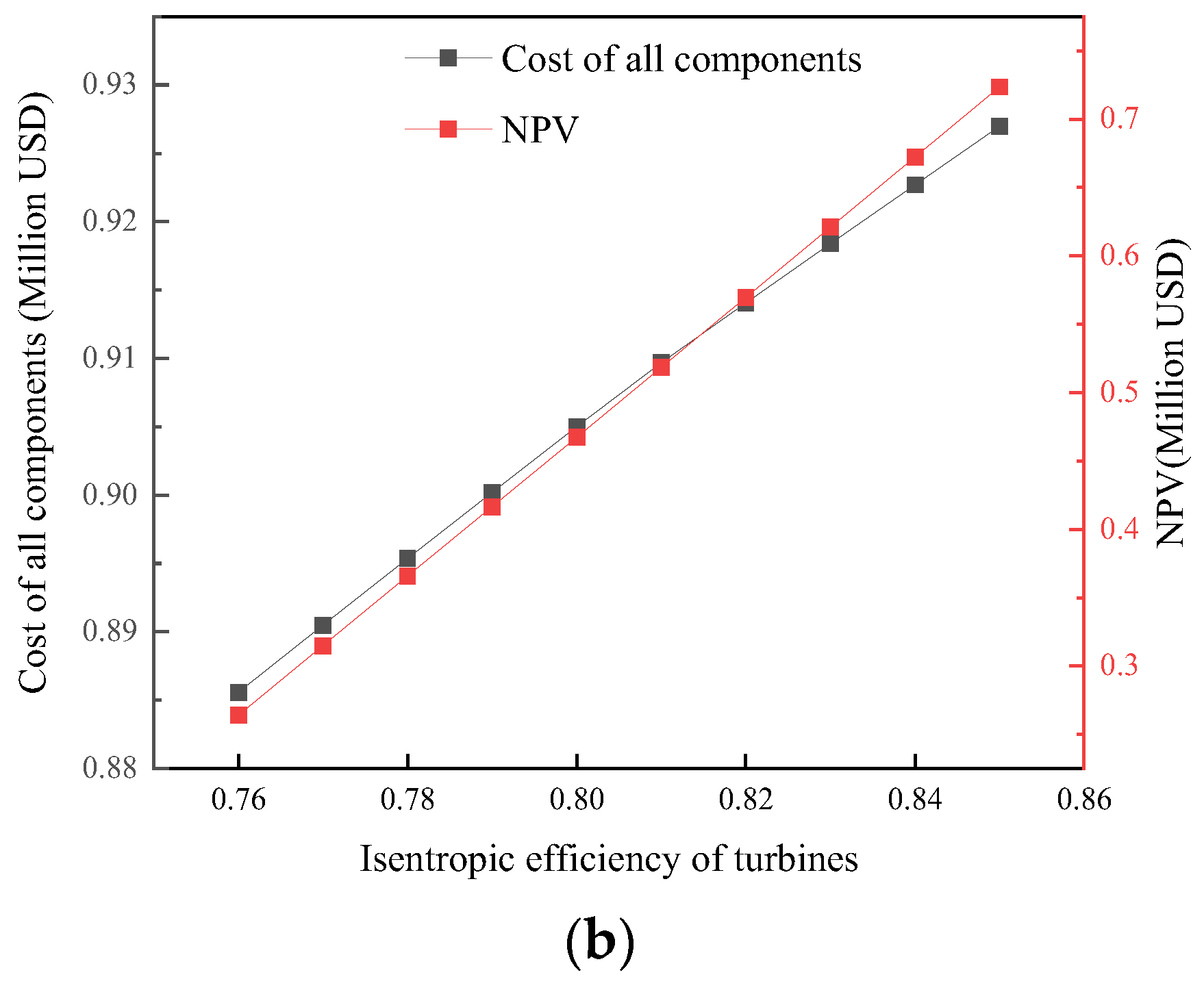
Figure 6 shows the effect of the isentropic efficiency of the pumps on the system. The set range of isentropic efficiency variation was 0.76 to 0.85. As the isentropic efficiency increased, as shown in Figure 6a, the pump power of the RC and ORC systems decreased, while the system energy efficiency slightly increased. The increase in isentropic efficiency indicated an improvement in the operational performance of the equipment, which led to a reduction in power consumption at the same boost ratio. The system energy efficiency increased under the condition of constant output power. The system equipment cost decreased with an increase in isentropic efficiency and the NPV was significantly improved, as shown in Figure 6b. The isentropic efficiency of the pumps was positively correlated with system performance, and the maximum value should be taken within a reasonable range.

5.6. Turbine Isentropic Efficiency Effect

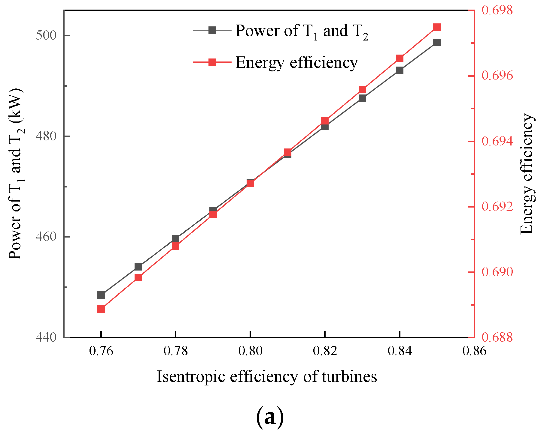
Figure 7 shows the effect of the isentropic efficiency of the turbines on system performance. The isentropic efficiency of the turbines had a direct impact on system performance, like the pump isentropic efficiency. The difference between the turbines and the pumps was that the pump isentropic efficiency affected power consumption, while the turbine isentropic efficiency affected power output. The range of values for the isentropic efficiency of the turbines was from 0.76 to 0.85. As the turbine isentropic efficiency increased, the output power and energy efficiency of the system turbines were significantly improved, as shown in Figure 7a.
The output power increased from 448 kW to 498 kW. The equipment cost and the NPV of the system also increased with the increase in the turbine isentropic efficiency, as shown in Figure 7b. The higher the isentropic efficiency of the turbines, the better the various parameters of the system. The influence of the isentropic efficiency of the pumps was opposite to the turbine isentropic efficiency data variation trend.

5.7. Exergy Analysis

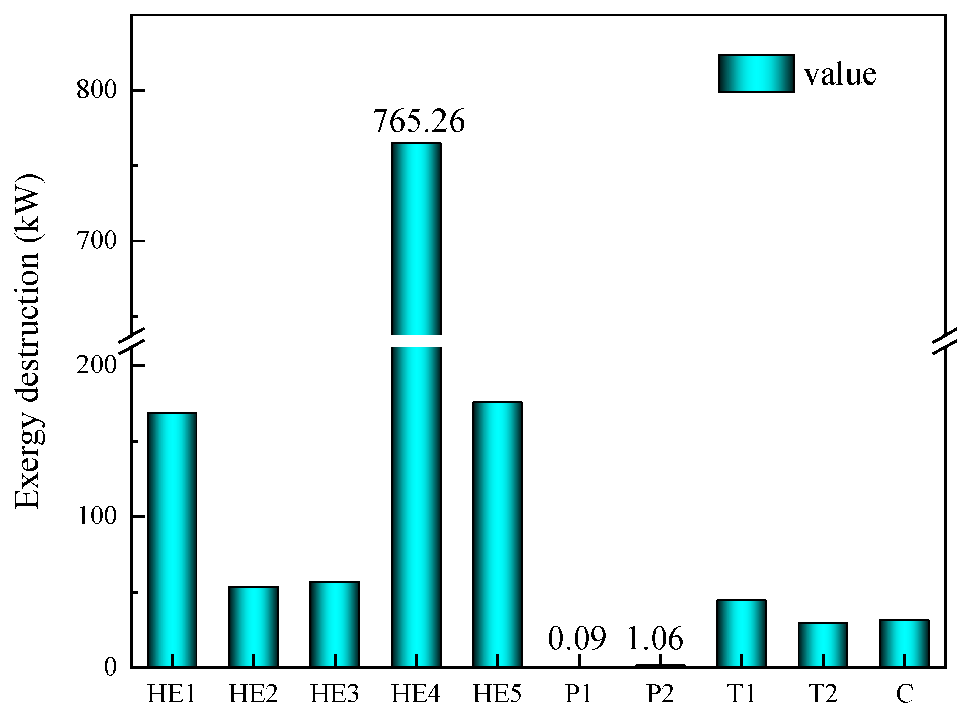
The results of the system exergy analysis are presented in Figure 8. Due to the high probability of the system NPV values to range from 0 to 1, this study selected the state where the system NPV was equal to million USD 0.55. The HE1 evaporation pressure was 720 kPa in the component exergy analysis. HE4 had the highest equipment exergy loss of 765.26 kW among all components, while P1 had the smallest loss of 0.09 kW. Among the other components, the exergy losses of HE1 and HE5 both exceeded 160 kW, which were second only to that of HE4. HE2 and HE3 had relatively small exergy losses of about 50 kW in the heat exchanger. The exergy losses of the turbines and the compressor of the system were also not significant, with both being below 50 kW. HE4 was the flue gas heat exchanger, which had the largest heat transfer temperature difference. The evaporation temperature of the HP system was relatively low. A reduction in the heat transfer loss of HE4 was the way to improve system energy efficiency. The exergy performance of the pumps and turbines in the system was good, which indicated that the equipment was stable and reliable.
This study analyzed the feasibility of a novel combined system for the waste heat recovery of waste incineration flue gas. The results show that the thermodynamic and economic performance of the combined system is good. This study was based on modeling analysis, and further experimental research is necessary. Separate experimental studies of the RC, ORC and HP systems are available. An experimental analysis is required to investigate the response characteristics and parameter optimization of the combined system.

6. Conclusions

This study was based on the principle of cascade waste heat recovery from waste incineration flue gas with consideration of safety and efficiency, and proposed a new heat recovery system composed of RC, ORC and HP systems. A detailed thermodynamic and economic analysis of the system was conducted. The system model was validated by the experimental data, showing it to be feasible and accurate. The optimal configurations of the system were determined through parameter analysis. The selection principles of the important parameters and the irreversible loss distribution of the components provided guidance for subsequent optimization of the system. The main conclusions of this study are as follows:
  • The maximum energy efficiency of the combined system can reach 73%. The evaporation pressure of the evaporator and the condensation temperature of the condenser in the RC system are proportional to the system efficiency.
  • The energy efficiency of the system is generally inversely proportional to its economy. It is not advisable to blindly pursue energy efficiency, as it is necessary to comprehensively consider the cost of system components.
  • The higher the isentropic efficiency of the pumps and turbines in the combined system, the better the system performance. The irreversible losses of the pumps and turbines are minimized based on the exergy analysis results.
  • The highest NPV of the system reaches million USD 1.59, and the system’s DDP is approximately 6.5 years.

Author Contributions

Methodology, J.L.; software, J.L.; formal analysis, J.L.; investigation, J.L.; data curation, J.L.; writing—original draft, J.L.; writing—review and editing, X.C.; supervision, X.C.; project administration, X.C. All authors have read and agreed to the published version of the manuscript.

Funding

This research was funded by the Natural Sciences Foundation of Guangxi Province (grant no. 2023JJA180032).

Data Availability Statement

The raw data supporting the conclusions of this article will be made available by the authors upon request.

Conflicts of Interest

The authors declare no conflicts of interest.

Nomenclature

Abbreviation
CCompressor
DPPDynamic investment payback period
GGenerator
HEHeat exchanger
NPVNet present value
ORCOrganic Rankine cycle
RCRankine cycle
TTurbine
VValve
Symbol
AArea ( m 2 )
cpSpecific heat capacity (kJ/(kg·K))
EExergy (kW)
IDExergy destruction (kW)
eSpecific exergy (kJ/kg)
hSpecific enthalpy (kJ/kg)
idDiscount rate
mFlow rate (kg/s)
QHeat transfer (kW)
WPower (kW)
Subscripts and superscripts
aThe environmental state
iInput
oOutput

References

  1. Zhang, R.; Cao, J.; Lei, L.; Cao, Y.; Liu, D. Pilot-tests of the coal-fired power plant indirect coupling with multi-source organic solid waste incineration technology. Fuel 2024, 369, 131740. [Google Scholar] [CrossRef]
  2. Bae, J.; Lee, S.; Kim, K.; Kang, J.; Jeon, T. Reassessment of lower heating value calculations for municipal solid waste incineration facilities in South Korea. Energy 2024, 293, 130669. [Google Scholar] [CrossRef]
  3. Deng, J.; Wu, G.; Xia, Y.; Liu, L. Preparation and Hydration Properties of Sodium Silicate-Activated Municipal Solid Waste Incineration Bottom Ash Composite Ground-Granulated Blast Furnace Slag Cementitious Materials. Materials 2024, 17, 2406. [Google Scholar] [CrossRef] [PubMed]
  4. Zhou, S.; Luo, H.; Feng, B.; Zheng, W.; Zeng, C.; Zhang, W.; Liu, J.; Xing, F. Research on using municipal solid waste incineration bottom ash for cement-stabilized macadam. Constr. Build. Mater. 2024, 425, 135850. [Google Scholar] [CrossRef]
  5. Bae Kim, Y.; Park, H.; Kim, Y. An empirical study on thermal efficiency and dusty moisture removal efficiency using enthalpy wheel in industrial waste incineration plant. Appl. Therm. Eng. 2024, 248, 123203. [Google Scholar] [CrossRef]
  6. Chen, H.; Guo, S.; Song, X.; He, T. Design and evaluation of a municipal solid waste incineration power plant integrating with absorption heat pump. Energy 2024, 294, 131007. [Google Scholar] [CrossRef]
  7. Wang, J.; Tian, H.; Wang, X.; Li, L.; Sun, R.; Bian, X.; Shu, G.; Liang, X. Process design methodology for rankine cycle based on heat matching. Renew. Sustain. Energy Rev. 2024, 193, 114295. [Google Scholar] [CrossRef]
  8. Guerron, G.; Nicolalde, J.F.; Martinez-Gomez, J.; Davila, P. Implementation of a waste heat recovery prototype facility based on the Rankine cycle with a twin-screw expander. Appl. Therm. Eng. 2024, 257, 124233. [Google Scholar] [CrossRef]
  9. Biancini, G.; Cioccolanti, L.; Moradi, R.; Moglie, M. Comparative study of steam, organic Rankine cycle and supercritical CO2 power plants integrated with residual municipal solid waste gasification for district heating and cooling. Appl. Therm. Eng. 2024, 241, 122437. [Google Scholar] [CrossRef]
  10. Kindra, V.; Maksimov, I.; Patorkin, D.; Rogalev, A.; Rogalev, N. Thermodynamic Analysis and Optimization of Binary CO2-Organic Rankine Power Cycles for Small Modular Reactors. Energies 2024, 17, 2377. [Google Scholar] [CrossRef]
  11. Lebedevas, S.; Cepaitis, T. Complex Use of the Main Marine Diesel Engine High- and Low-Temperature Waste Heat in the Organic Rankine Cycle. J. Mar. Sci. Eng. 2024, 12, 521. [Google Scholar] [CrossRef]
  12. Mirzaei, M.R.; Kasaeian, A.; Motlagh, M.S.; Fereidoni, S. Thermo-economic analysis of an integrated combined heating, cooling, and power unit with dish collector and organic Rankine cycle. Energy 2024, 296, 131089. [Google Scholar] [CrossRef]
  13. Besevli, B.; Kayabasi, E.; Akroot, A.; Talal, W.; Alfaris, A.; Assaf, Y.H.; Nawaf, M.Y.; Bdaiwi, M.; Khudhur, J. Technoeconomic Analysis of Oxygen-Supported Combined Systems for Recovering Waste Heat in an Iron-Steel Facility. Appl. Sci. 2024, 14, 2563. [Google Scholar] [CrossRef]
  14. Lyu, L.; Kan, A.; Chen, W.; Zhang, Y.; Fu, B. Energy, Exergy and Environmental Analysis of ORC Waste Heat Recovery from Container Ship Exhaust Gases Based on Voyage Cycle. J. Mar. Sci. Eng. 2023, 11, 2029. [Google Scholar] [CrossRef]
  15. Liu, H.; Lu, B.; Xu, Y.; Ju, X.; Wang, W.; Zhang, Z.; Shi, L.; Tian, H.; Shu, G. Experimental investigation of a splitting organic Rankine cycle for dual waste heat recovery. Energ. Convers. Manag. 2024, 320, 119005. [Google Scholar] [CrossRef]
  16. Wang, C.; Liu, S.; Zhan, S.; Ou, M.; Wei, J.; Cheng, X.; Zhuge, W.; Zhang, Y. Transcritical dual-loop Rankine cycle waste heat recovery system for China VI emission standards natural gas engine. Energy 2024, 292, 130577. [Google Scholar] [CrossRef]
  17. Ravindran, R.V.; Cotter, D.; Wilson, C.; Huang, M.J.; Hewitt, N.J. Experimental investigation of a small-scale reversible high-temperature heat pump-organic Rankine cycle system for industrial waste heat recovery. Appl. Therm. Eng. 2024, 257, 124237. [Google Scholar] [CrossRef]
  18. Feng, J.; Yan, Y.; Cheng, X.; Zhao, L.; Dong, H. Thermal-economic performance evaluation and bi-objective optimization of organic Rankine cycles using pure and mixed working fluids for waste heat recovery. Case Stud. Therm. Eng. 2024, 60, 104750. [Google Scholar] [CrossRef]
  19. Zhang, C.; Li, L.; Guo, X.; Hu, B.; Li, Z. Potential analysis of a waste heat recovery combined system based on recuperator and organic Rankine cycle on rotorcraft powerplant. Case Stud. Therm. Eng. 2024, 55, 104136. [Google Scholar] [CrossRef]
  20. Zhou, X.; Xin, Z.; Tanga, W.; Sheng, K.; Wu, Z. Comparative study for waste heat recovery in immersion cooling data centers with district heating and organic Rankine cycle (ORC). Appl. Therm. Eng. 2024, 242, 122479. [Google Scholar] [CrossRef]
  21. Ali, M.I.H.; Abdelsamie, M.M. Thermoeconomic evaluation of waste heat recovery system in aluminium smelters using a parallel two-stage organic Rankine cycle. Energ. Convers. Manag.-X 2024, 23, 100648. [Google Scholar]
  22. Zhang, Q.; Huang, H.; Zhai, H.; Zhao, W.; Lu, X. Experimental research on direct expansion heat pump flue gas waste heat recovery and humidification nitrogen reduction system. J. Clean. Prod. 2023, 406, 137000. [Google Scholar] [CrossRef]
  23. Jang, Y.; Lee, D.; Kim, J.; Ham, S.H.; Kim, Y. Performance characteristics of a waste-heat recovery water-source heat pump system designed for data centers and residential area in the heating dominated region. J. Build. Eng. 2022, 62, 105416. [Google Scholar] [CrossRef]
  24. Ghaderi, M.; Reddick, C.; Sorin, M. A Systematic Heat Recovery Approach for Designing Integrated Heating, Cooling, and Ventilation Systems for Greenhouses. Energies 2023, 16, 5493. [Google Scholar] [CrossRef]
  25. Zhou, Y.; Peng, B.; Zhu, B. Assessment of Optimal Operating Range and Case Verification of a Waste Heat Air-Source Heat Pump Water Heater Based on a Semiempirical Parametric Model. Energies 2023, 16, 2289. [Google Scholar] [CrossRef]
  26. Ma, D.; Sun, Y.; Ma, S.; Li, G.; Zhou, Z.; Ma, H. Study on the working medium of high temperature heat pump suitable for industrial waste heat recovery. Appl. Therm. Eng. 2024, 236, 121642. [Google Scholar] [CrossRef]
  27. Vannoni, A.; Sorce, A.; Traverso, A.; Massardo, A.F. Techno-economic optimization of high-temperature heat pumps for waste heat recovery. Energ. Convers. Manag. 2023, 290, 117194. [Google Scholar] [CrossRef]
  28. Meftahpour, H.; Saray, R.K.; Aghaei, A.T.; Bahlouli, K. Comprehensive analysis of energy, exergy, economic, and environmental aspects in implementing the Kalina cycle for waste heat recovery from a gas turbine cycle coupled with a steam generator. Energy 2024, 290, 130094. [Google Scholar] [CrossRef]
  29. Lu, B.; Shi, L.; Tian, H.; Wang, X.; Shu, G. CO2-mixture-based ship waste heat recovery system (SWHRS) with multiple energy outputs and composition-adjustable mixture. Energ. Convers. Manag. 2022, 251, 114994. [Google Scholar] [CrossRef]
  30. Zhao, Y.; Li, W.; Zhao, X.; Wang, Y.; Luo, D.; Li, Y.; Ge, M. Energy and exergy analysis of a thermoelectric generator system for automotive exhaust waste heat recovery. Appl. Therm. Eng. 2024, 239, 122180. [Google Scholar] [CrossRef]
  31. Brahimi, F.; Madani, B.; Ghemmadi, M. Comparative Thermodynamic Environmental and Economic Analyses of Combined Cycles Using Air and Supercritical CO2 in the Bottoming Cycles for Power Generation by Gas Turbine Waste Heat Recovery. Energies 2022, 15, 9066. [Google Scholar] [CrossRef]
  32. Zhao, X.; Chen, H.; Li, S.; Li, W.; Pan, P.; Liu, T.; Wu, L.; Xu, G. Thermodynamic and economic analysis of a novel design combining waste tire pyrolysis with silicon production waste heat recovery and organic Rankine cycle. Energy 2023, 283, 128500. [Google Scholar] [CrossRef]
  33. Nami, H.; Anvari-Moghaddam, A. Small-scale CCHP systems for waste heat recovery from cement plants: Thermodynamic, sustainability and economic implications. Energy 2020, 192, 116634. [Google Scholar] [CrossRef]
  34. Carneiro, M.L.N.M.; Gomes, M.S.P. Energy, exergy, environmental and economic analysis of hybrid waste-to-energy plants. Energ. Convers. Manag. 2019, 179, 397–417. [Google Scholar] [CrossRef]
  35. Galloni, E.; Fontana, G.; Staccone, S. Design and experimental analysis of a mini ORC (organic Rankine cycle) power plant based on R245fa working fluid. Energy 2015, 90, 768–775. [Google Scholar] [CrossRef]
  36. Ommen, T.; Jensen, J.K.; Markussen, W.B.; Reinholdt, L.; Elmegaard, B. Technical and economic working domains of industrial heat pumps: Part 1-Single stage vapour compression heat pumps. Int. J. Refrig.-Rev. Int. Du. Froid 2015, 55, 168–182. [Google Scholar] [CrossRef]
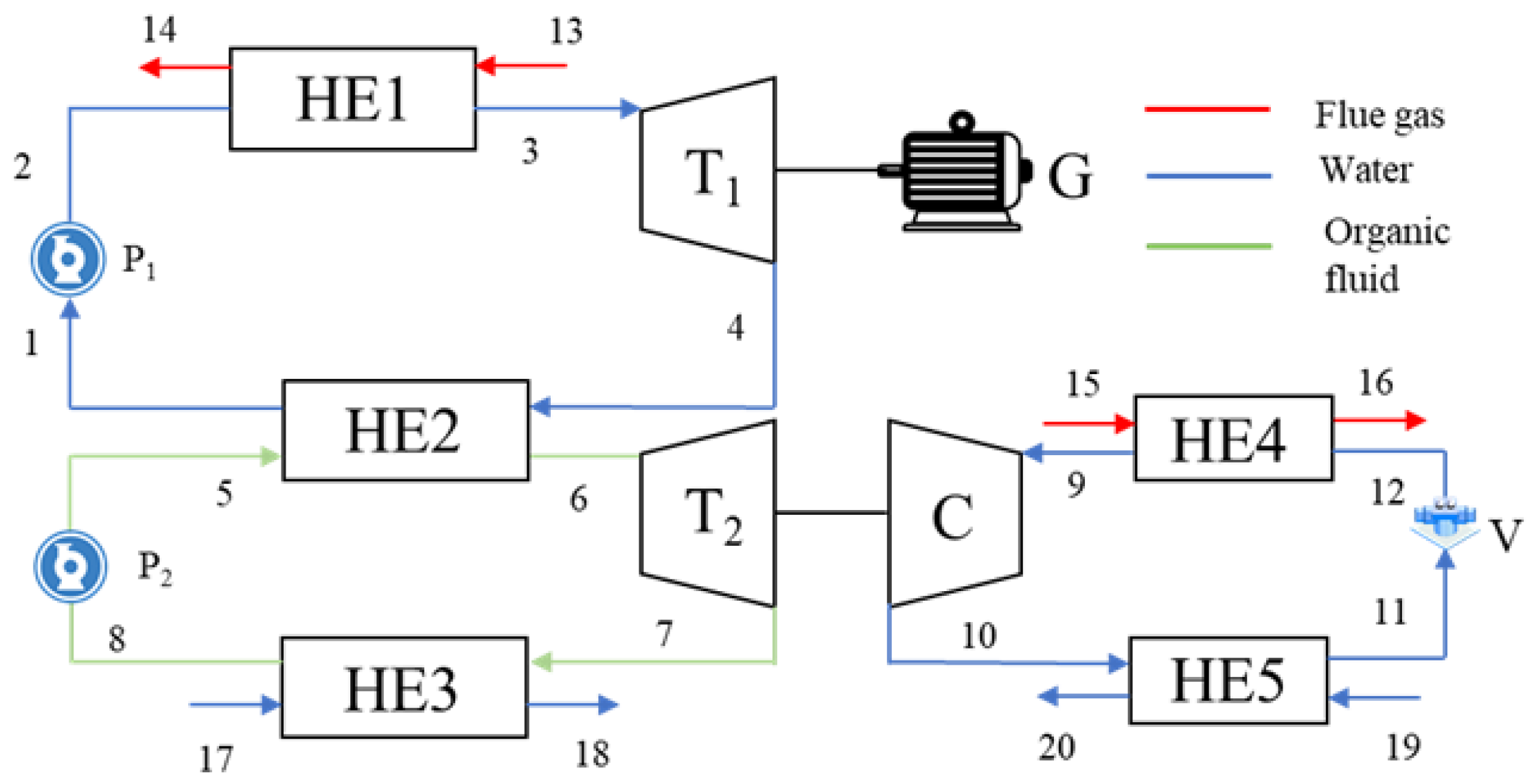
Figure 1. The composition of the cascade heat recovery system.
Energies 17 05196 g001
Figure 2. The effect of evaporation pressure of HE1: (a) power of T1 and mass flow of RC; (b) energy efficiency and NPV.
Energies 17 05196 g002
Figure 3. The effect of evaporation temperature of HE4: (a) power of WC and mass flow of HP; (b) cost of compressor and NPV.
Energies 17 05196 g003
Figure 4. The effect of T20: (a) exergy destruction of HE5 and cost of all components; (b) NPV curve.
Energies 17 05196 g004
Figure 5. The effect of HE2 condensation temperature: (a) power of WT2 and mass flow of ORC; (b) energy efficiency and NPV.
Energies 17 05196 g005
Figure 6. The effect of isentropic efficiency of pump: (a) power of P1 and P2 and energy efficiency; (b) cost of all components and NPV.
Energies 17 05196 g006
Figure 7. The effect of isentropic efficiency of turbines: (a) power of T1 and T2 and energy efficiency; (b) cost of all components and NPV.
Energies 17 05196 g007aEnergies 17 05196 g007b
Figure 8. Exergy analysis results.
Energies 17 05196 g008
Table 1. The parameters of system modeling.
ParameterValue
Flue gas temperature463.15–513.15 K
Isentropic efficiency of turbine0.85
Isentropic efficiency of pumps and compressors0.85
Evaporator pinch-point temperature difference30 K
Pinch-point temperature difference of condenser5 K
Table 2. System control equations based on energy balance.
Control VolumeEquations
HE1 m ˙ R C h 3 h 2 = m ˙ g c ˙ p , g T 13 T 14
HE2 m ˙ R C h 4 h 1 = m ˙ O R C h 6 h 5
HE3 m ˙ O R C h 7 h 8 = m ˙ 17 c ˙ p , w T 18 T 17
HE4 m ˙ H P h 9 h 12 = m ˙ g c ˙ p , g T 15 T 16
HE5 m ˙ H P h 10 h 11 = m ˙ 19 c ˙ p , w T 20 T 19
T1 W ˙ T 1 = m ˙ R C h 3 h 4 , η T 1 = h 3 h 4 h 3 h 4 s
T2 W ˙ T 2 = m ˙ O R C h 6 h 7 , η T 2 = h 6 h 7 h 6 h 7 s
P1 W ˙ P 1 = m ˙ R C h 2 h 1 , η P 1 = h 2 s h 1 h 2 h 1
P2 W ˙ P 2 = m ˙ O R C h 5 h 8 , η P 2 = h 5 s h 8 h 5 h 8
C W ˙ C = m ˙ H P h 10 h 9 , η c = h 10 s h 9 h 10 h 9
Table 3. System control equations based on exergy balance.
Control Volume I i I o I D
HE1 E ˙ 13 E ˙ 14 E ˙ 3 E ˙ 2 E ˙ 13 + E ˙ 2 E ˙ 3 E ˙ 14
HE2 E ˙ 4 E ˙ 1 E ˙ 6 E ˙ 5 E ˙ 4 + E ˙ 5 E ˙ 1 E ˙ 6
HE3 E ˙ 7 E ˙ 8 E ˙ 18 E ˙ 17 E ˙ 7 + E ˙ 17 E ˙ 7 E ˙ 18
HE4 E ˙ 15 E ˙ 16 E ˙ 9 E ˙ 12 E ˙ 15 + E ˙ 12 E ˙ 9 E ˙ 16
HE5 E ˙ 10 E ˙ 11 E ˙ 20 E ˙ 19 E ˙ 10 + E ˙ 19 E ˙ 11 E ˙ 20
T1 E ˙ 3 E ˙ 4 W ˙ T 1 E ˙ 3 E ˙ 4 W ˙ T 1
T2 E ˙ 6 E ˙ 7 W ˙ T 2 E ˙ 6 E ˙ 7 W ˙ T 2
P1 W ˙ P 1 E ˙ 2 E ˙ 1 W ˙ P 1 + E ˙ 1 E ˙ 2
P2 W ˙ P 2 E ˙ 5 E ˙ 8 W ˙ P 2 + E ˙ 8 E ˙ 5
C W ˙ c E ˙ 10 E ˙ 9 W ˙ c + E ˙ 9 E ˙ 10
Table 4. Cost equation of each system component.
Control VolumeEquations
HE1 C HE1 = 309.14 A HE 1 0.85
HE2 C HE2 = 280.74 Q 2.2 Δ T HE2 + 746 m RC
HE3 C HE2 = 280.74 Q 2.2 Δ T HE3 + 746 m ORC
HE4 C HE4 = 309.14 A HE 1 0.85
HE5 C HE2 = 280.74 Q 2.2 Δ T HE5 + 746 m HP
T1 C T 1 = 6000 W T 1 0.7
T2 C T 2 = 6000 W T 2 0.7
P1 C p 1 = 3450 W P 1 0.71
P2 C p 2 = 3450 W P 2 0.71
C C C = 3450 W C 0.71
Table 5. Validation of ORC and HP systems.
ParameterThis StudyReferences [35,36]Difference
Heat transfer of ORC evaporator10.87 kW10.88 kW0.09%
Heat transfer of ORC condenser9.79 kW9.87 kW0.81%
Energy efficiency of ORC9.86%9.28% 6.25%
Heat transfer of HP evaporator896.7 kW855 kW4.88%
Heat transfer of HP condenser1049.7 kW1000 kW4.97%
Energy efficiency of HP6.86%6.5%5.54%
Disclaimer/Publisher’s Note: The statements, opinions and data contained in all publications are solely those of the individual author(s) and contributor(s) and not of MDPI and/or the editor(s). MDPI and/or the editor(s) disclaim responsibility for any injury to people or property resulting from any ideas, methods, instructions or products referred to in the content.