Abstract
An AC (alternative current) power integration of distributed energies faces multi-fold challenges such as synchronization and weak grid-induced instability. In this study, a multi-terminal DC transformer is proposed for renewable energy clusters grid connection. The DC transformer provides multiple DC input ports for renewable energy collection, while the load port is connected to the medium-voltage DC grid via a modular multilevel converter (MMC). The multi-port topology enables flexible power transfer between multiple input sources to the load without additional components. The carrier layer modulation strategy is implemented to balance the MMC module voltage; bidirectional power transmission between multiple input sources is achieved through the phase shift modulation (PSM) method. First, we provided a detailed introduction of the proposed topology and working principle. A simulation model was built using the SIMULINK, and the simulation results verified the effectiveness of the proposed converter modulation strategy and phase shift modulation method. A corresponding hardware experimental platform was designed and built, and the modulation and voltage equalization functions of modular multilevel rectifiers were presented as well as the measured results of power transmission modulation of the converter under single-input and multi-input conditions. The results indicate that the proposed transformer can achieve multiple DC inputs and has multi-channel power transmission capabilities, making it suitable for renewable energy clusters grid connection.
1. Introduction
As the integration of renewable energy deepens, the shortcomings of traditional AC distribution systems in managing the variability of energy supply and demand become increasingly apparent. DC distribution technology, which revolves around high-power converters, can enhance the integration of multiple energy sources, swiftly adapt to fluctuating loads, and offer a flexible energy supply [1,2]. The literature suggests that due to the dispersed nature of renewable energy, the prevailing grid connection approach is to employ single-input converters for each energy source, convert the energy locally, and subsequently integrate it into the grid [3,4].
A DC microgrid necessitates the ability to integrate various forms of energy, accommodate any variation in load demands, and maintain high power quality. Multi-terminal DC transmission involves a DC network with more than two converters, enabling multiple systems requiring grid integration to participate and enhancing the utilization rate of DC transmission lines [5,6]. Compared to traditional point-to-point transmission lines, this structure is relatively cost effective. It also offers operational flexibility, allowing any two AC systems to exchange power accurately through the multi-terminal DC system. Moreover, it possesses robust fault tolerance; should any terminal fail, it can be isolated from the DC network without disrupting the normal operation of other terminals [7]. ABB has crafted a classic example where the front-end input on the DC side features a single-input structure. The AC output of each wind turbine is rectified and merged into a 3 kV DC common bus, which then passes through an isolated step-up DC converter to achieve a 33 kV medium-voltage DC for long-distance transmission. An inverter subsequently converts the DC back to AC for delivery to the receiving AC grid. This system is highly flexible, facilitates power flow control, and boasts high efficiency. The system’s block diagram is depicted in Figure 1.
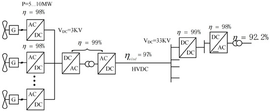
Figure 1.
Multi-terminal high-voltage DC transmission system framework diagram.
Compared to traditional distribution grid connection technology, the performance demands for high-power converters in renewable energy grid-connected systems are growing increasingly stringent. Conventional grid connection systems often employ two-level converters. To elevate the voltage level, it is frequently necessary to connect numerous power switching devices in series on each bridge arm, which complicates voltage balancing. Moreover, constrained by the number of output levels, the switching frequency must be increased to achieve the desired voltage levels, leading to a significant rise in switching losses [8,9].
In traditional high-voltage direct current transmission, a mature technology has been used for decades, which uses AC transformers for boosting and 12 pulse thyristor bridge control for rectification and power flow. This technology is robust and reliable, but it requires each transformer to be bulky, complex, and expensive for the conversion (rectification and inversion) of power frequency transformers. Many types of topologies for power transmission in DC microgrids have been developed [10], and the optimal solution needs to be selected according to the application scenario. Therefore, the application of DC transformers in DC microgrid systems has significant advantages. Firstly, there are no reactive power or phase issues in DC microgrids, making the system structure simpler, switching easier, and stability enhanced. Secondly, DC transformers can achieve multi-voltage level DC bus interconnection, which is beneficial for power flow control and improves the flexibility and reliability of system power supply. At present, the power flow control of DC converters mostly adopts the DC side voltage PID control strategy to ensure constant voltage to achieve power flow control. Although this control strategy is simple, its response speed to system changes is slow, making it difficult to achieve precise power flow control. At the same time, for multilevel converters, it is difficult to achieve the voltage balance of parallel capacitors in submodules, which has obvious system defects. Recently, the application of DC transformers in renewable energy full DC collection and DC transmission and distribution has become a hot research topic [11,12].
Against this backdrop, this paper introduces a multi-input direct current (DC) transformer for renewable energy grid-connected systems, as depicted in Figure 2. This transformer has the capability to replace multiple traditional single-input DC converters, enabling various energy sources to deliver power to the load either individually or concurrently within a single switching cycle. This approach enhances system flexibility, facilitates the prioritized use of energy, and helps to reduce overall system costs. Moreover, to meet the demands of high-step-up and step-down applications, the multi-input DC transformer employs an isolated topology. In terms of control strategy, in order to better achieve power flow control and the voltage balance of submodule parallel capacitors, a control strategy combining constant voltage control and phase stacked modulation is adopted to achieve load distribution, overcoming the challenges of stability and coordinated control that may be encountered in multi-terminal DC systems.
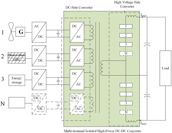
Figure 2.
Topology of multi-input isolated high-power DC-DC converter.
2. Configuration of the Multi-Terminal DC Converter
2.1. Multi-Terminal Isolated High-Power DC Transformer Structure
The multi-terminal isolated high-power direct current (DC) transformer, as an innovative power electronic conversion device, effectively integrates renewable energy with energy storage elements. This integration enhances the converter’s power density, reliability, and transient response speed, making it highly promising for applications in distributed renewable energy grid-connected systems.
From Figure 2, the transformation device proposed in this paper is structured into three main components: the DC side converter, the multi-winding transformer, and the high-voltage side converter. Dispersed renewable energy sources are first rectified and then converted into AC with the same frequency but different phases through a full-bridge rectifier. These are supplied to the individual windings of the transformer’s primary side. Utilizing the transformer for voltage stepping up, the secondary side features a single-winding output. The medium-voltage AC is subsequently rectified into the medium-voltage DC necessary for DC transmission by a modular multilevel converter. This configuration not only capitalizes on the transformer’s voltage stepping-up and isolation protection capabilities but also fully exploits the benefits of the modular multilevel converter. As a high-voltage, high-capacity power converter, the modular multilevel converter offers a range of topological advantages. It addresses many of the limitations of traditional two-level inverters, providing benefits such as high-quality output waveforms, reduced switching frequency, lower stress on switching devices, and enhanced efficiency.
The multi-terminal DC converter proposed in this article can be used not only in distributed renewable energy grid-connected systems but also in electrified transportation systems, such as ships and railways. It only requires changing the capacity of the DC transformer according to the application scenario without changing the topology of the converter [13,14,15].
2.2. Modular Multilevel Converter with Half-Bridge Submodules Topology
The modular multilevel converter (MMC) is widely utilized in high-voltage direct current (HVDC) transmission scenarios due to its ability to withstand high voltages, maintain low harmonic content without the need for AC filters, and operate at low-switching frequencies, among other advantages. The MMC’s high modularity, with submodules operating relatively independently, enhances the system’s reliability. While it is commonly used as an inverter in various applications, its topology can also function as a rectifier [16,17]. In this paper, considering factors such as power modulation methods and losses, the chosen topology is the single-phase modular multilevel converter with half-bridge submodules, as shown in Figure 3.
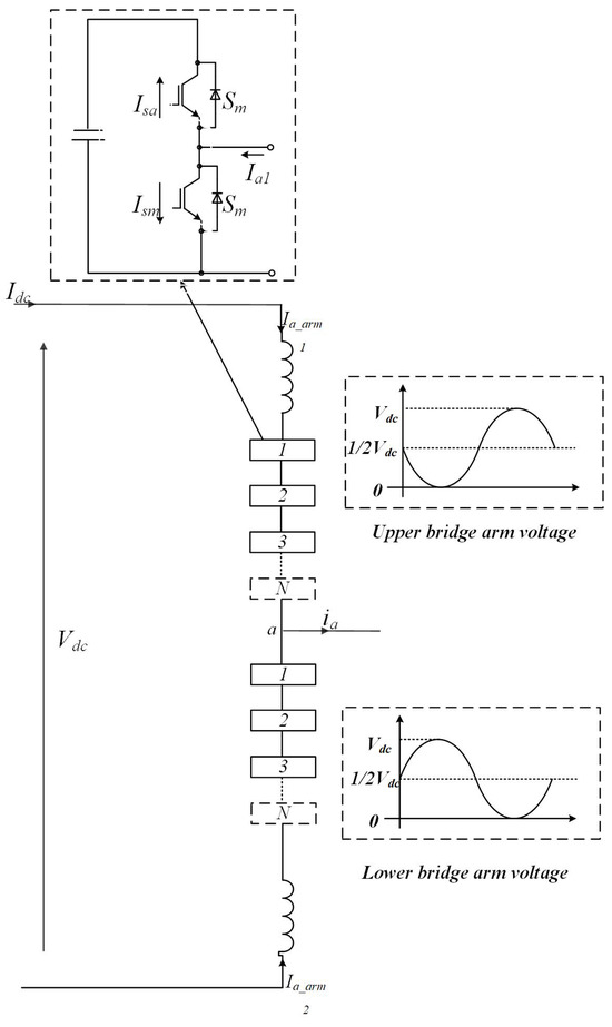
Figure 3.
Topology of single-phase modular multilevel converter with half-bridge submodules.
The paper selects a three-level modular converter, as shown in Figure 4. Each submodule consists of two MOSFETs and one capacitor. The current direction is defined as positive from left to right. When the current is positive, switch is on and switch is off, resulting in an output voltage of 0. When the current is negative, the current flows through the anti-parallel diode of , also resulting in an output voltage of 0. These two states represent the submodule cut-off condition. When the current is positive, switch is on and switch is off, resulting in an output voltage of . When the current is negative, the current flows through the anti-parallel diode of , also resulting in an output voltage of . This state represents the submodule connection condition [18,19]. Therefore, the half-bridge submodule operates in four normal modes, as depicted in Figure 4.
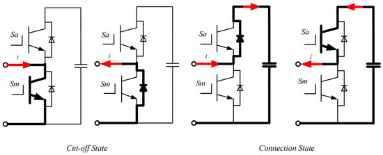
Figure 4.
Submodule operating modes (The red arrow indicates the direction of the working current of the submodule).
According to the above diagram, the output voltage is zero when the submodule is operating in the disconnected mode. The current flows alternately through the switch and the anti-parallel diode without charging the capacitor, thus maintaining a constant capacitor voltage. In conductive mode, the capacitor is charged and discharged as the current direction changes, resulting in an output voltage equal to the capacitor voltage. There is also a blocking mode. In the event of a submodule failure, both and switches can be turned off simultaneously to protect the components.
2.3. Mathematical Model
The construction and analysis of a mathematical model is essential for understanding the operating mechanisms and control strategies of modular multilevel converters (MMCs). This modeling also provides essential guidelines for the design of the main circuit parameters. Prior to normal operation, it is necessary to pre-charge the parallel capacitors in each submodule to reach a predefined voltage reference. Assuming the capacitor voltage during normal operation is , with N half-bridge submodules connected in series on both the upper and lower arms, and each submodule having identical parameters, each submodule will output either 0 or . Each submodule therefore acts as a controllable voltage source. The series-connected submodules in the upper and lower arms are equivalent to two controlled voltage sources and . We assume currents and in the upper and lower arms, respectively, the AC output and the DC bus current [20,21,22]. The primary circuit structure of a single-phase MMC is shown in Figure 5.
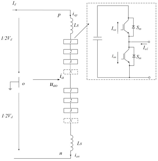
Figure 5.
Submodule operating modes.
From Figure 5, and can be observed as follows,
Output phase voltage is as follows:
Based on the introduction in the previous section, assuming that the voltage and capacitors in the submodule are balanced, the on–off states of the two switches can either disconnect or connect the DC source with a voltage of in series with the upper or lower arm. The output voltage magnitude of the submodule ranges from 0 to , and its output voltage is determined by the switch state of the nth submodule, .
The voltages on the upper and lower arms of the bridge are , :
Furthermore, is obtained:
Substituting Equation (4) into the above equation, we obtain as follows:
Equations (7) and (9) together form the mathematical model of the single-phase modular multilevel converter.
3. Modulation Methods
This paper adopts the phase-disposition (PD) modulation strategy, utilizing an N-level MMC that necessitates (N-1) triangle carriers of identical frequency and amplitude. Gate signals for each switch are determined by comparing a sinusoidal modulation waveform with the carriers. When the sinusoidal modulation signal exceeds the carrier signal, the associated active switches for that carrier are turned on. Conversely, when the modulation signal is lower, these switches are turned off. The intermediate section operates in pulse width modulation (PWM) mode. This approach decouples PWM control from voltage balancing control, facilitating the independent implementation of each.
In the context of a modular multilevel converter, the modulation ratio ’m’ and frequency can be determined as follows [23,24,25,26]:
and represent the modulation amplitude and carrier signal amplitude, respectively, while and represent their respective frequencies.
As shown in Figure 6, there are two triangular carrier waves and , and one sinusoidal modulation wave . For a three-level inverter, the output voltage is 1/2 when the sinusoidal wave exceeds the first triangular wave and −1/2 when the sinusoidal wave is lower than the second triangular wave . In all other cases, the output voltage is 0.
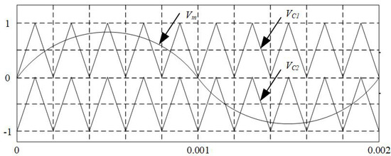
Figure 6.
Carriers and modulation waveform for three-level MMC.
Figure 7 illustrates four different switch combinations when the converter output voltage is zero. In Figure 7a, the switch combination (1010) indicates that the output point is connected between and , leading to voltage imbalance. Assuming the current direction indicated in Figure 7a is positive, when > 0, capacitor discharges and capacitor charges. Conversely, when < 0, capacitor charges and capacitor discharges.
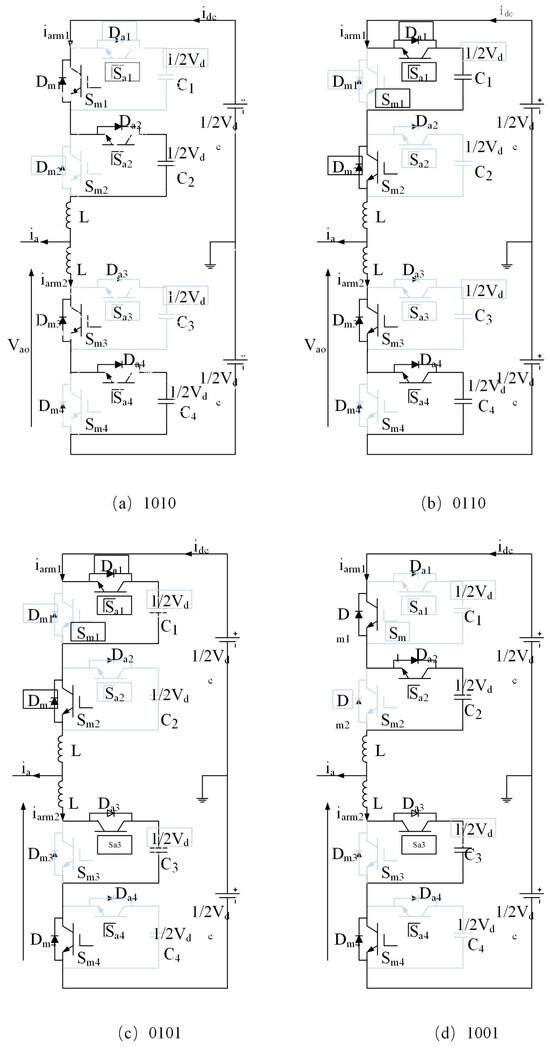
Figure 7.
The four switching states of the three-level MMC.
To achieve balanced voltages across all paralleled capacitors within each submodule, the following steps are taken. Firstly, the current operational mode (charging or discharging) of each submodule is determined. Next, the basic units of the upper and lower arms of the bridge are arranged in order of capacitor voltage with lower voltage units set to charge or bypass, higher voltage units set to discharge or bypass, and mid-range voltage units operating in the PWM mode. This ensures that during each PWM cycle, the capacitor with the highest voltage is discharged or bypassed, while the capacitor with the lowest voltage is charged or bypassed, dynamically balancing the voltages across all capacitors.
4. Power Flow Control Analysis
The input terminals of the multi-terminal DC converter proposed in this article are connected to DC voltages such as photovoltaic output, wind power rectification output, and energy storage module. Due to the similar characteristics of each input source, the power flow control analysis of DC converters is equivalent to analyzing single-input and single-output converters.
This section simplifies the multi-terminal DC transformer topology proposed in the paper into a single-input isolated converter with DC transformer as the core. The primary side of the transformer employs a full-bridge inverter circuit, while the secondary side is connected to a modular multilevel converter (three-level MMC). Power transmission from left to right indicates forward power transfer with the capability for reverse power flow as well. The primary side of the single-port input transformer generates a 50% duty cycle square wave voltage, while the secondary side features a three-level SPWM voltage waveform. Active power transmission excludes orthogonal harmonic components, and studying power transmission characteristics involves filtering out high-frequency harmonics from the secondary side to obtain a sinusoidal fundamental waveform. Additionally, the secondary side of the transformer is equivalently modeled on the primary side using a leakage inductance , as depicted in Figure 8.
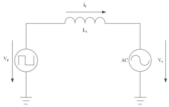
Figure 8.
Equivalent circuit of single-input isolated DC-DC converter.
The converter shown in the above figure employs 180° phase shift modulation, where the two switches in the same bridge arm conduct complementarily. Power transmission is achieved by phase shifting the voltages between the primary and secondary sides of the transformer. When the phase of the primary side voltage leads by an angle , power flows from left to right, indicating forward transmission. Conversely, when the phase of lags by , power flows from right to left, indicating reverse transmission.
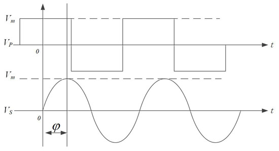
Figure 9.
Phase relationship between transformer primary and secondary sides.
According to Kirchhoff’s voltage law (KVL), the following can be deduced: = −
Next, we obtain the current entering the transformer through Laplace transformation from Equation (14):
Combining Equation (12) and Equation (15), the average power flowing through the transformer can be determined as
where (T) is the switching period.
According to the derived formulas, the relationship between the power and phase shift angle is shown in Figure 10, where the vertical axis is scaled by .
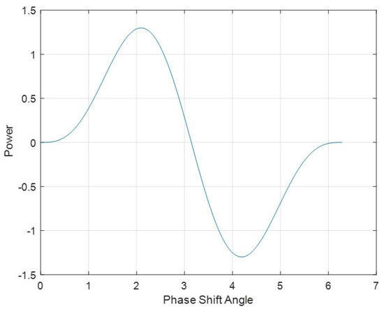
Figure 10.
Relationship between power and phase shift angle.
5. System Simulation and Analysis
To assess the operational characteristics and control strategy of the entire system, a simulation model was established using Matlab/Simulink 2018b. The model is a single-input single-output system that includes a full-bridge inverter circuit, a transformer with a transformation ratio of 1:1, and a modular multilevel conversion circuit. Table 1 shows the parameters of the components in the secondary side three-level conversion circuit of the transformer. Table 2 shows the simulation circuit parameters of the three-level converter.

Table 1.
Effects of switching combinations on capacitor voltages in three-level modular multilevel converters.

Table 2.
Circuit parameters of three-level converter.
5.1. Voltage Balance of Parallel Capacitors in Submodules
Figure 11 illustrates the voltage situation of each unit capacitor. The graph shows that the voltage values of the four units fluctuate around (200 V) as the reference with a ripple of less than 1%. This demonstrates the effectiveness of the carrier superimposed modulation strategy in maintaining the voltage balance of the submodule capacitors.
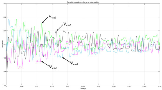
Figure 11.
Dynamic values of submodule voltage.
5.2. Voltage and Current of DC Transformer Port
The bus voltage of the full-bridge inverter circuit is 200 VDC. The system simulation results are shown in Figure 12. The primary side voltage of the transformer is the square wave voltage output from the full-bridge inverter. The secondary side voltage is the SPWM (sinusoidal pulse width modulation) voltage output of the three-level converter. The current is the excitation current flowing through the primary side magnetizing inductance of the transformer. The voltage and current waveforms on the secondary side conform to the and analyzed by Formulas (6) and (9) in Section 2.3.
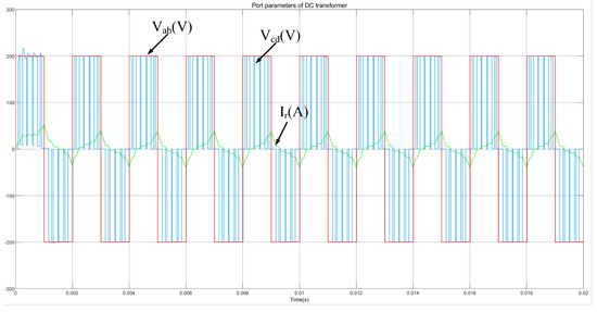
Figure 12.
Port voltage and current.
5.3. Power Flow Control
Figure 13 depicts the relationship between the bus current at port A and the phase shift angle. When the phase of the primary side voltage (port A) leads the phase of the secondary side voltage (port B), power flows from left to right, and the current at port A is positive. Conversely, when the phase of the primary side voltage lags behind the secondary side voltage, the current at port A is negative. The relationship between the phase shift angle and the theoretical analysis of power transmission is consistent with the scanning results of the bus current at port A.
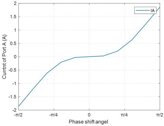
Figure 13.
Relationship between port A bus current and phase shift angle.
5.4. Control of Output Voltage
In order to verify the performance of the proposed system under the actual operating conditions of renewable energy cluster power grids, the ability to stabilize the output voltage is essential. In the simulation model, changing one of the input voltage values simulates the sudden changes in photovoltaic, wind power, and energy storage voltages in the actual system. The simulation results are shown in Figure 14.
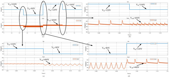
Figure 14.
(b–d) are local enlargements of the voltage change points in (a).
According to Figure 14b–d, it can be seen that when the input voltage of the system decreases from 100 to 80 V, then rises to 120 V, and finally returns to 100 V, the output voltage can always maintain 400 V throughout the entire change process. Therefore, in the face of actual input changes in application scenarios, the system has good stable output capability.
6. Experimental Validation
The experiment is limited by laboratory conditions and uses a DC bus voltage of 20 V to simulate and verify. To validate the rationality of the proposed topology, the feasibility of the control strategy, and the accuracy of the simulation results, a two-input isolated DC transformer prototype was designed. The prototype mainly consists of five parts: the main circuit, sampling circuit, driver circuit, auxiliary power supply, and microcontroller. The experimental platform is shown in Figure 15. Two DC power supplies were used to simulate the rectified voltages of photovoltaic and wind power generation. Power resistors were used as the load.
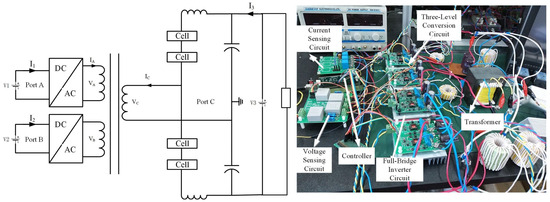
Figure 15.
Experimental system platform.
6.1. Transformer Three-Terminal Voltage Validation
The experimental platform is shown in Figure 15. During the experiment, the two input terminals were connected to 20 V DC, and the output terminal was connected to a 40 V DC load in parallel with a 4 ohm resistor. The voltage of the three ports of the transformer was verified, and the voltage waveforms are shown in Figure 16. From the figure, it can be seen that the voltages at the two input ports of the transformer, and , are both 500 Hz AC, while the output port voltage is a three-level AC voltage of ±20 V and 0. The phase difference between and is 0.2 with and leading in phase. The primary side current of the transformer is also given. The experimental results for voltage and current are largely consistent with the theoretical analysis and simulation results, and the voltage waveform confirms the effectiveness of the MMC modulation strategy. Due to the handmade nature of the transformer, there are discrepancies between the inductance parameters and the simulation settings, resulting in some distortion in the experimental waveforms.
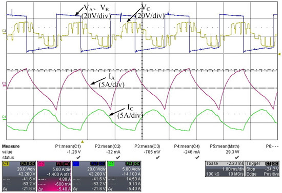
Figure 16.
The voltages at the three terminals of the transformer and the primary side current.
6.2. Power Flow Control Verification
In this paper, power transmission is divided into two modes: mode I (power transmission from port A to port C) and mode II (simultaneous power transmission from ports A and B to port C). In both modes, the phase difference between the port voltages is 0.2. The current variations at port C are shown in Figure 17.
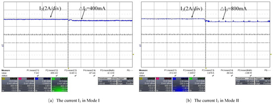
Figure 17.
The current response at the bus side under different power transmission modes.
Mode I: The DC side voltage at port A is , and the DC side voltage at port C is .
Mode II: The DC side voltage at port A is , the DC side voltage at port B is , and the DC side voltage at port C is .
According to Figure 17, when power is supplied from port A, the DC side current at port C decreases by 400 mA, indicating that the system power flows from left to right. When power is supplied from both port A and port B simultaneously, the DC side current at port C decreases by 800 mA, demonstrating that power is being transmitted from ports A and B to port C.
The paper also verifies the relationship between power transmission and the phase difference between port voltages. By ensuring that the phase of voltages at ports A and B leads that of port C, variations in power transmission are validated by altering the phase difference.
Mode I: With the DC side voltages at the ports remaining constant, when the phase shift angle is , the port voltages, currents, and power are shown in Figure 18.
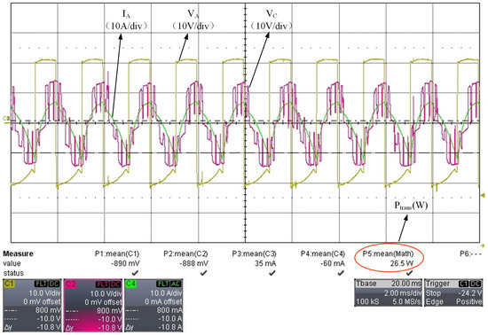
Figure 18.
The port voltages and currents for mode I.
According to Figure 18, when the phase shift angle is , both ports A and B transmit power to port C at 26.5 W.
Mode II: With the DC side voltages at the ports remaining constant, when the phase shift angle is , the port voltages, currents, and power are shown in Figure 19.
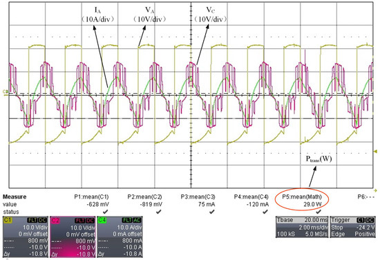
Figure 19.
The port voltages and currents for mode II.
According to Figure 19, when the phase shift angle is , the power transmitted from ports A and B to port C is 29 W. The experimental results of power transmission under both modes and their relationship with the phase shift angle align with theoretical and simulation analyses.
7. Conclusions
In the current energy structure transformation, the integration and utilization of renewable energy have become important issues. The multi-terminal DC transformer proposed in this article is an innovative power electronic device that can achieve power transmission and distribution between multiple renewable energy sources, which is of great significance for improving the flexibility and reliability of the power grid. The multi-terminal DC transformer utilizes the phase disposition (PD) modulation strategy and phase-shift power modulation method. The PD modulation strategy optimizes the output voltage waveform of the transformer by adjusting the voltage waveforms of different phases, reducing harmonic content and improving power quality. At the same time, it can effectively achieve the balance of submodule voltage and ensure the stable operation of the transformer. The phase-shift power modulation method achieves precise control of the output voltage and power of the transformer by adjusting the phase difference between the primary and secondary sides of the transformer.
In addition, multi-terminal DC transformers also achieve instantaneous power transmission between multiple ports of the transformer. This means that transformers can quickly distribute power between different ports to adapt to the dynamic changes and demands of the power grid. This rapid response capability is crucial for dealing with the volatility and uncertainty of renewable energy sources, such as the output power of solar and wind energy, which can vary with weather and time.
The experimental results show that this multi-input DC transformer effectively handles multiple DC inputs and supports multi-channel power transmission. This indicates that multi terminal DC transformers have good performance and reliability in practical applications. It can not only improve the operational efficiency of the power grid but also reduce costs because compared to traditional power conversion equipment, it reduces the number of required power electronic components as well as the complexity and maintenance costs of the system. It is expected that this type of transformer will play a more important role in the future smart grid.
Author Contributions
Writing—original draft, F.Z.; Writing—review & editing, T.K. and S.H. All authors have read and agreed to the published version of the manuscript.
Funding
This research received no external funding.
Data Availability Statement
The original contributions presented in the study are included in the article, further inquiries can be directed to the corresponding author.
Conflicts of Interest
The authors declare no conflicts of interest.
References
- Li, Y.; Liu, H.; Chi, Y.; Fan, X.; Tian, X.; Zhang, Z. Requirement Analysis on Large-scale Renewable Energy DC Collection and Transmission Technology. In Proceedings of the 2020 4th International Conference on HVDC (HVDC), Xi’an, China, 6–9 November 2020; pp. 410–414. [Google Scholar] [CrossRef]
- Khan, M.U.; Wali, K.; Karimov, K.S.; Saeed, M.A. A new proposed hierarchy for renewable energy generation to distribution grid integration. In Proceedings of the 2015 International Conference on Emerging Technologies (ICET), Peshawar, Pakistan, 19–20 December 2015; pp. 1–6. [Google Scholar] [CrossRef]
- Xiang, X.; Wei, Z.; Jie, Z.; Ning, X.; Qi, X. Key technologies and applications of AC/DC hybrid distributed renewable energy system. In Proceedings of the 2018 International Conference on Power System Technology (POWERCON), Guangzhou, China, 6–9 November 2018; pp. 4265–4631. [Google Scholar] [CrossRef]
- Gumilar, L.; Sholeh, M.; Cahyani, D.E.; Kusumawardana, A.; Habibi, M.A.; Akhmadi, S.F. Comparison of Renewable Energy Output Power Transmission to Loads Via HVAC and HVDC. In Proceedings of the 2021 4th International Seminar on Research of Information Technology and Intelligent Systems (ISRITI), Yogyakarta, Indonesia, 16–17 December 2021; pp. 458–463. [Google Scholar] [CrossRef]
- Elangovan, S. Recent trends in sustainable development of renewable energy. In Proceedings of the 2017 International Conference on Advances in Electrical Technology for Green Energy (ICAETGT), Coimbatore, India, 23 September 2017; pp. 148–150. [Google Scholar] [CrossRef]
- Krzywinski, G. Integrating storage and renewable energy sources into a DC Microgrid using high gain DC DC Boost Converters. In Proceedings of the 2015 IEEE First International Conference on DC Microgrids (ICDCM), Atlanta, GA, USA, 7–10 June 2015; pp. 251–256. [Google Scholar] [CrossRef]
- Alim, M.A.; Khan, M.A.G.; Munjer, M.A. CSMC-SPWM modular multilevel converter for HVDC transmission system. In Proceedings of the 2016 5th International Conference on Informatics, Electronics and Vision (ICIEV), Dhaka, Bangladesh, 13–14 May 2016; Volume 3, pp. 771–775. [Google Scholar]
- Duan, Y.; Zhang, X.; Yang, X.; Qiao, Y.; Xiao, G. The Modular Multilevel Converter Based Multi-Terminal DC Transformer with Controllable Power Flow. In Proceedings of the 2018 IEEE International Power Electronics and Application Conference and Exposition (PEAC), Shenzhen, China, 4–7 November 2018; pp. 1–6. [Google Scholar] [CrossRef]
- Erat, A.; Vural, A.M. An Innovative DC-DC Modular Multilevel Converter Topology for Interconnection Asynchronous High Voltage Direct Current Power Grids. In Proceedings of the 2023 14th International Conference on Electrical and Electronics Engineering (ELECO), Bursa, Turkiye, 30 November–2 December 2023; pp. 1–5. [Google Scholar] [CrossRef]
- Raveendhra, D.; Poojitha, R.; Narasimharaju, B.L.; Dreglea, A.; Liu, F.; Panasetsky, D.; Pathak, M.; Sidorov, D. Part-I: State-of-the-Art Technologies of Solar Powered DC Microgrid with Hybrid Energy Storage Systems-Architecture Topologies. Energies 2023, 16, 923. [Google Scholar] [CrossRef]
- Gray, P.A.; Ma, Z.C.; Lehn, P.W. A High-Frequency MMC for DC–DC Applications Using a Three-Winding Transformer with DC Flux Cancellation. IEEE J. Emerg. Sel. Top. Ind. Electron. 2022, 3, 647–657. [Google Scholar] [CrossRef]
- Denniston, N.; Massoud, A.M.; Ahmed, S.; Enjeti, P.N. Multiple-Module High-Gain High-Voltage DC–DC Transformers for Offshore Wind Energy Systems. IEEE Trans. Ind. Electron. 2011, 58, 1877–1886. [Google Scholar] [CrossRef]
- Ma, F.; Wang, X.; Deng, L.; Zhu, Z.; Xu, Q.; Xie, N. Multiport Railway Power Conditioner and Its Management Control Strategy with Renewable Energy Access. IEEE J. Emerg. Sel. Top. Power Electron. 2020, 8, 1405–1418. [Google Scholar] [CrossRef]
- Chen, J.; Zhao, Y.; Lin, H.; Wei, Y.; Liu, W.; Guo, Q.; Li, Y.R.; Mantooth, H.A. Analysis and Control of Cascaded Energy Storage System for Energy Efficiency and Power Quality Improvement in Electrified Railways. IEEE Trans. Transp. Electrif. 2024, 10, 1299–1313. [Google Scholar] [CrossRef]
- Chen, P.; Xiao, F.; Liu, J.; Zhu, Z.; Ren, Q. Unbalanced Operation Principle and Fast Balancing Charging Strategy of a Cascaded Modular Multilevel Converter–Bidirectional DC–DC Converter in the Shipboard Applications. IEEE Trans. Transp. Electrif. 2020, 6, 1265–1278. [Google Scholar] [CrossRef]
- Han, J.; Liu, C. Quasi Proportional Resonant Controller Based MMC Grid Side Harmonic Suppression Research. In Proceedings of the 2022 IEEE International Conference on Power Systems and Electrical Technology (PSET), Aalborg, Denmark, 13–15 October 2022; pp. 240–245. [Google Scholar] [CrossRef]
- Hazem, K.M.; Moustafa, M.M.Z. Performance and control of a back to back MMC-HVDC for asynchronous ac networks interconnection. In Proceedings of the 2015 IEEE 28th Canadian Conference on Electrical and Computer Engineering (CCECE), Halifax, NS, Canada, 3–6 May 2015; pp. 1066–1071. [Google Scholar] [CrossRef]
- Rohner, S.; Bernet, S.; Hiller, M.; Sommer, R. Modelling, simulation and analysis of a Modular Multilevel Converter for medium voltage applications. In Proceedings of the 2010 IEEE International Conference on Industrial Technology, Via del Mar, Chile, 14–17 March 2010; pp. 775–782. [Google Scholar]
- Adam, G.P.; Anaya-Lara, O.; Burt, G.M.; Telford, D.; Williams, B.W.; McDonald, J.R. Modular multilevel inverter: Pulse width modulation and capacitor balancing technique. IET Power Electron. 2010, 3, 702–715. [Google Scholar] [CrossRef]
- Carrara, G.; Gardella, S.; Marchesoni, M.; Salutari, R.; Sciutto, G. A new multilevel PWM method: A theoretical analysis. IEEE Trans. Power Electron. 1990, 31, 363–371. [Google Scholar]
- Liu, X.; Wang, D.; Guo, G.; Wen, J.; Li, J.; Wang, X. The multi-level simplified simulation of MMC based on half-bridge sub-models. In Proceedings of the 2016 35th Chinese Control Conference (CCC), Chengdu, China, 27–29 July 2016; pp. 9935–9941. [Google Scholar] [CrossRef]
- Jin, Y.; Tang, A.; Huang, Y.; Zheng, X.; Xu, Q. Research for Equivalent Mathematical Model of MMC-DPFC. In Proceedings of the 2017 International Conference on Industrial Informatics—Computing Technology, Intelligent Technology, Industrial Information Integration (ICIICII), Wuhan, China, 2–3 December 2017; pp. 231–236. [Google Scholar] [CrossRef]
- Tolbert, L.M.; Habetler, T.G. Novel multilevel inverter carrier-based PWM methods. In Proceedings of the Conference Record of 1998 IEEE Industry Applications Conference. Thirty-Third IAS Annual Meeting (Cat. No.98CH36242), St. Louis, MO, USA, 12–15 October 1998; Volume 2, pp. 1424–1431. [Google Scholar]
- Hagiwara, M.; Akagi, H. Control and Experiment of Pulse width-Modulated Modular Multilevel Converters. IEEE Trans. Power Electron. 2009, 24, 1737–1746. [Google Scholar] [CrossRef]
- Chumei, F.; Agelidis, V.G. On the comparison of fundamental and high frequency carrier-based PWM techniques for multilevel NPC inverters. In Proceedings of the 2002 IEEE 33rd Annual IEEE Power Electronics Specialists Conference. Proceedings (Cat. No.02CH37289), Cairns, QLD, Australia, 23–27 June 2002; Volume 2, pp. 520–525. [Google Scholar]
- Steinke, J.K. Switching frequency optimal PWM control of a three-level inverter. IEEE Trans. Power Electron. 1992, 7, 487–496. [Google Scholar] [CrossRef]
Disclaimer/Publisher’s Note: The statements, opinions and data contained in all publications are solely those of the individual author(s) and contributor(s) and not of MDPI and/or the editor(s). MDPI and/or the editor(s) disclaim responsibility for any injury to people or property resulting from any ideas, methods, instructions or products referred to in the content. |
© 2024 by the authors. Licensee MDPI, Basel, Switzerland. This article is an open access article distributed under the terms and conditions of the Creative Commons Attribution (CC BY) license (https://creativecommons.org/licenses/by/4.0/).