Review

Bionic Strategies for Pump Anti-Cavitation: A Comprehensive Review

1
College of Metrology Measurement and Instrument, China Jiliang University, Hangzhou 310018, China
2
Institute of Process Equipment, Zhejiang University, Hangzhou 310027, China
3
Key Laboratory of River Basin Digital Twinning of Ministry of Water Resources, China Institute of Water Resources and Hydropower Research, Beijing 100038, China
4
China Energy Technology and Economics Research Institute, China Energy Investment Corporation Ltd., Beijing 102211, China
*
Authors to whom correspondence should be addressed.
Energies 2024, 17(20), 5149; https://doi.org/10.3390/en17205149
Submission received: 17 September 2024 / Revised: 9 October 2024 / Accepted: 11 October 2024 / Published: 16 October 2024
(This article belongs to the Section K: State-of-the-Art Energy Related Technologies)

Abstract

:
The cavitation phenomenon presents a significant challenge in pump operation since the losses incurred by cavitation adversely impact pump performance. The many constraints of conventional anti-cavitation techniques have compelled researchers to explore biological processes for innovative alternatives. Consequently, the use of bionanotechnology for anti-cavitation pumping has emerged as a prominent study domain. Despite the extensive publication of publications on biomimetic technology, research concerning the use of anti-cavitation in pumps remains scarce. This review comprehensively summarizes, for the first time, the advancements and applications of bionic structures, bionic surface texture design, and bionic materials in pump anti-cavitation, addressing critical aspects such as blade leading-edge bionic structures, bionic worm shells, microscopic bionic textures, and innovative bionic coatings. Bionic technology may significantly reduce cavitation erosion and improve pump performance by emulating natural biological structures. This research elucidates the creative contributions of biomimetic designs and their anti-cavitation effects, hence boosting the anti-cavitation performance of pumps. This work integrates practical requirements and anticipates future applications of bionic technology in pump anti-cavitation, offering a significant research direction and reference for scholars in this domain.

Graphical Abstract

1. Introduction

Cavitation is a phase transition that takes place in a uniform liquid or at the boundary between a solid and a liquid. It is a process in which the local decrease in pressure in the flow field causes the formation, growth, and collapse of vacuoles. Cavitation then has a continuous effect on the boundary surface of the internal overflow components of a pump, leading to wall deformation and material spalling, known as cavitation erosion [1,2,3,4]. In 1893, scientists confirmed through observation the destruction of a British warship. The propeller’s disintegration was caused by cavitation erosion, marking the initial discovery of the cavitation erosion phenomenon. Subsequently, cavitation issues in hydraulic machinery, including propellers, turbines, and pumps, have been extensively studied. The cavitation phenomenon often occurs alongside intricate vortex formations and unstable flow within the impeller area, with similar hydrodynamic issues observed in other turbomachinery. Fluid instabilities, vortex formations, and localized pressure variations in hydraulic turbines, compressors, and wind turbines contribute to reduced equipment performance and fatigue damage to mechanical components [5,6]. These phenomena reduce system efficiency while inducing noise, vibration, wear, and damage to mechanical components [7,8,9,10]. In these devices, unstable flow often results from vortex shedding, fluid separation, and pressure pulsations, which can lead to significant shocks and material degradation in critical regions. Figure 1a illustrates the cavitation process. The collapse of bubbles can cause a sudden increase in pressure, and the resulting flow impacts on the worm casing and impeller can intensify noise and vibration in pumps and other turbomachinery [11,12]. A substantial quantity of air bubbles will obstruct the flow channel and disrupt the water movement, resulting in a rapid decrease in flow rate and efficiency [13,14]. In cases of severe cavitation, many bubbles infiltrate the high-pressure zone and implode, resulting in repeated impacts or potential damage to the blade surface, thereby exacerbating cavitation erosion, as seen in Figure 1b and Figure 2.
Since its inception in the 1960s, bionics has been applied in several domains, including engineering, design, chemistry, and electronics. It has emerged as a powerful catalyst for technological advancement [18,19,20]. This field consistently draws insights from nature by extensively studying and replicating its structures, mechanisms, and ecological systems. Illustrative examples of its breakthroughs and applications include reduced-drag configurations for animal structures, drag-minimizing techniques inspired by shark skin, and bionic robots modeled on the aerial movements of insects [21,22]. Furthermore, pioneering bionic designs in the realm of materials, including advancements in self-cleaning and self-repairing materials, as well as investigations into bio-adhesive technologies, have shown significant promise for practical applications.
Despite considerable progress, the existing techniques in the pump industry to address cavitation and cavitation erosion still face certain limitations and hurdles compared to bionic anti-cavitation technology. Regarding structural design, implementing strategies to improve pump efficiency, such as optimizing the impeller and increasing the inlet diameter and vane width, can significantly improve performance. However, these improvements introduce a higher level of design complexity and increased production costs [23,24,25]. Furthermore, incorporating an induced wheel to improve resistance to cavitation may increase both the volume and weight of the pump, thereby introducing new complexities to the overall design. It should be emphasized that these structural enhancements are generally applicable to certain pump types or operating situations and are not universally applicable. Implementing strict monitoring and modification at the operational level is crucial, such as regulating the liquid temperature and ensuring high suction tank pressure. These factors undoubtedly contribute to the complexity of management. External environmental variables, such as weather conditions and seasonal variations, may limit the application of these techniques. When confronted with frequent fluctuations in operating conditions, these approaches may respond with delays, posing challenges in maintaining the pump’s constant optimum performance [26,27,28]. Regarding material selection, the use of anti-cavitation materials can enhance the pump’s anti-cavitation performance to a certain extent. However, the performance of these materials varies greatly, and certain high-performance materials are costly, thereby further escalating the manufacturing cost [29,30,31,32]. Non-metallic coatings exhibit a certain level of resistance to cavitation, but their durability and stability are relatively insufficient, making them prone to detachment and wear. In addition, many media exhibit distinct corrosive and abrasive properties on materials, resulting in the limited applicability of specific vapor corrosion-resistant materials, thus significantly limiting their universality [33,34,35]. Hence, it is crucial to investigate novel approaches, such as bionic vapor corrosion resistance technology, to overcome the existing constraints and restrictions in the pump industry.
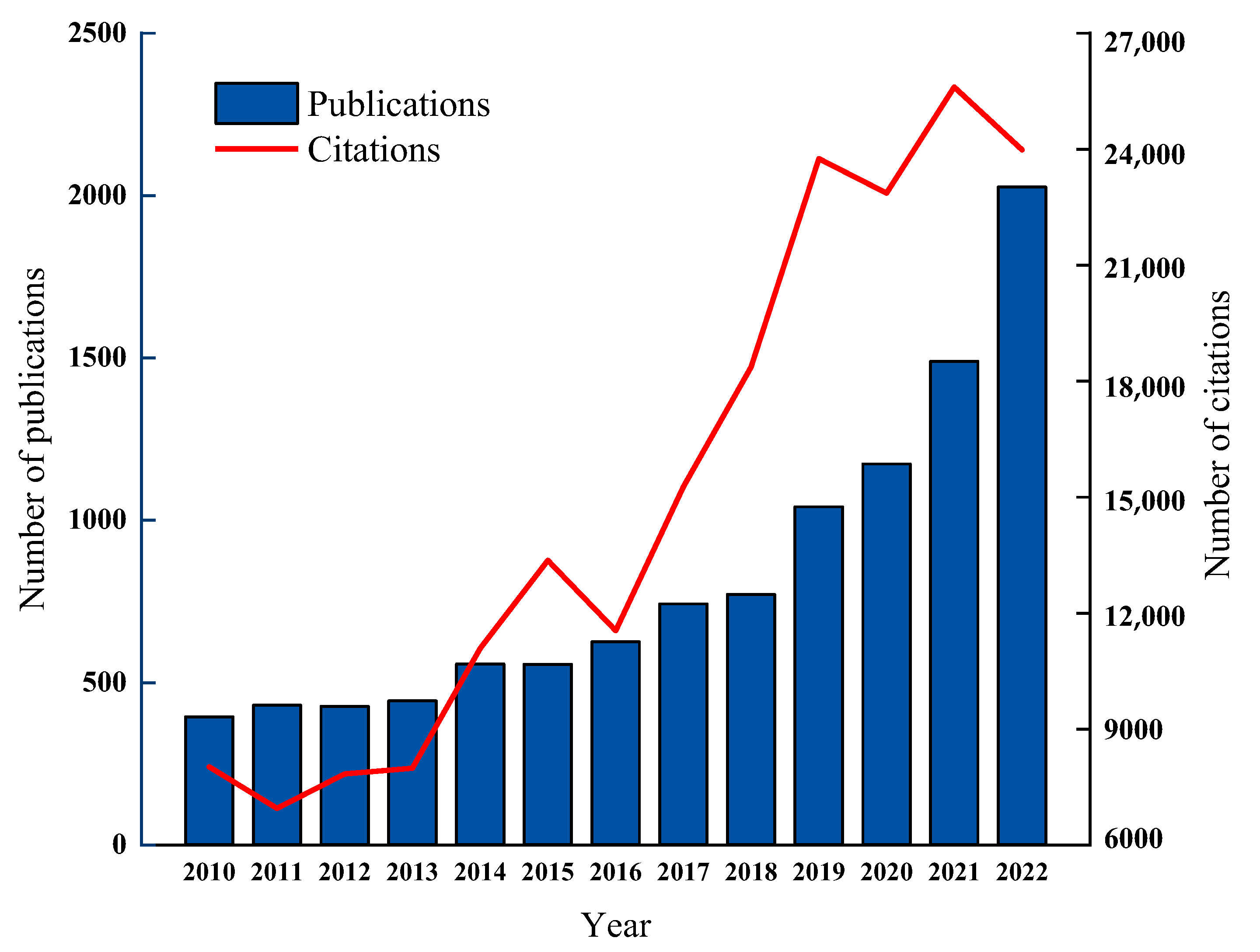
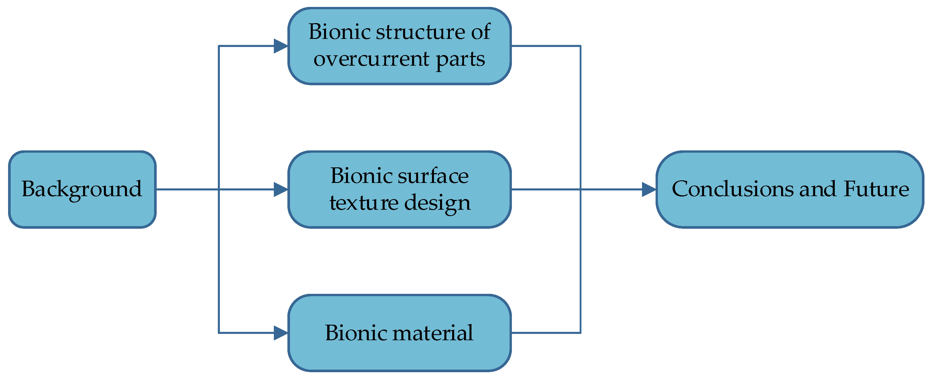
Figure 3 illustrates that pump anti-cavitation has emerged as a prominent research focus for enhancing pump performance over the past decade-plus. Despite the abundance of papers examining bionic technology, research on the application of anti-cavitation techniques in pumps remains relatively scarce. This report provides the first comprehensive overview of studies concerning the use of bionic technology in pump anti-cavitation in recent years. This paper aims to systematically gather and evaluate the published research using bionic technology as an anti-cavitation technique in pumps. The primary logical framework of this research is shown in Figure 4. Initially, this study outlines the limitations of traditional anti-cavitation techniques, emphasizing shortcomings in structural optimization and material selection. Secondly, the principles and practical effectiveness of alleviating the cavitation phenomenon in pumps through the design of bionic structures for the overflow components, specifically the bionic design of the leading edge of the vanes and the bionic worm shell, are examined. The design and application of bionic surface textures in pumps are comprehensively reviewed. Additionally, this study elucidates the innovative use of bionic materials, with a particular focus on the advancements in bionic coatings and composites. The potential of bionic technology for diverse applications in pump anti-cavitation is summarized, and future research areas are outlined. Bionanotechnology is identified as an efficient solution for addressing pump cavitation issues. It holds significant potential as it reduces energy consumption and promotes sustainable industrial growth by mitigating environmental impacts, including the reduction of cavitation noise and the minimization of hazardous material usage.

2. Bionic Structure of Overcurrent Parts

2.1. Bionic Structure of Leaf Blade Leading Edge

Leading-edge cavitation refers to a specific type of cavitation that tends to develop at the leading edge of the streamlined surface of a blade when hydrodynamic machinery operates outside its intended parameters [36,37,38]. Leading-edge cavitation is a primary form of cavitation observed in hydraulic machinery. It contributes to the erosion of the structural surface and induces large amplitude vibrations in the structure. Leading-edge cavitation often occurs following the detachment of the laminar boundary layer, and the pressure distribution in this area is strongly correlated with the length of the vacuole [39,40,41].
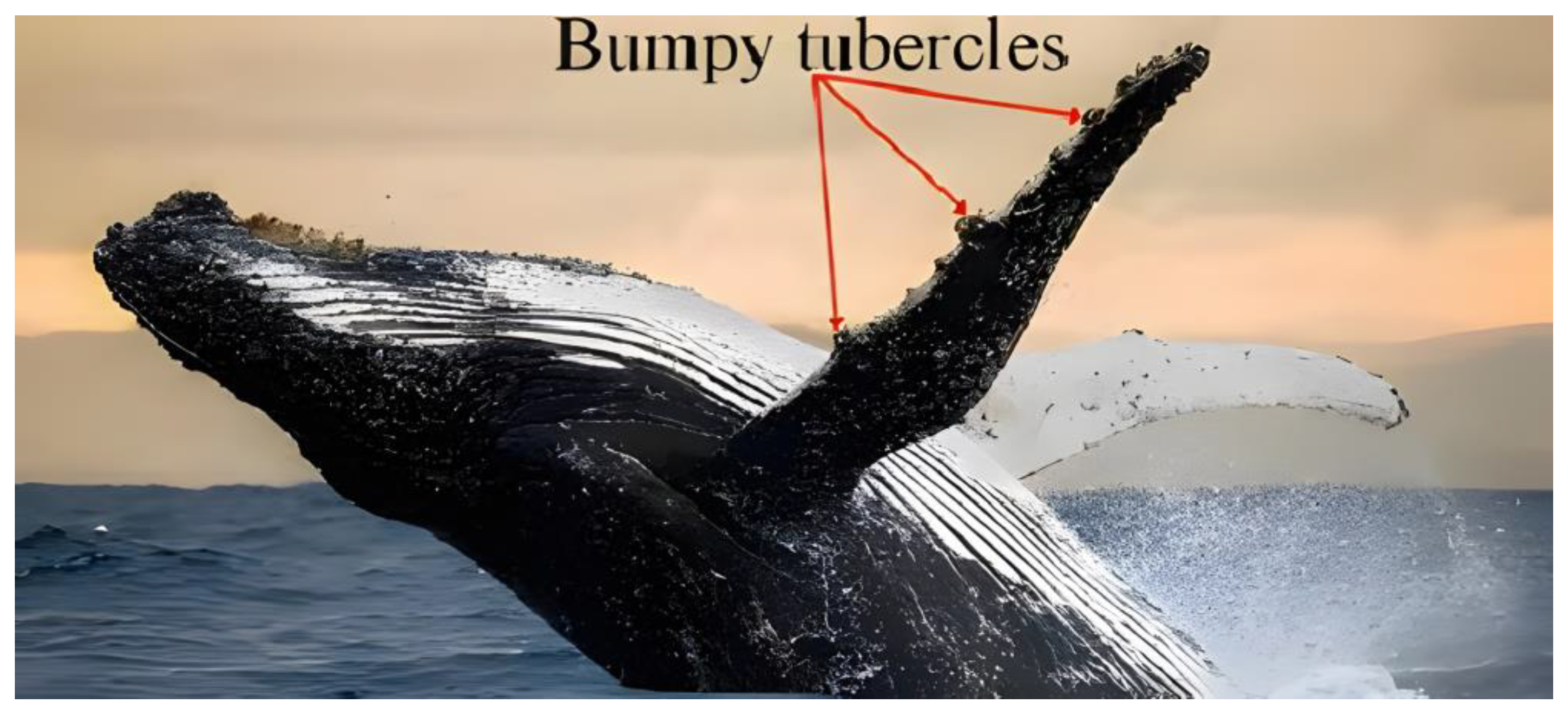
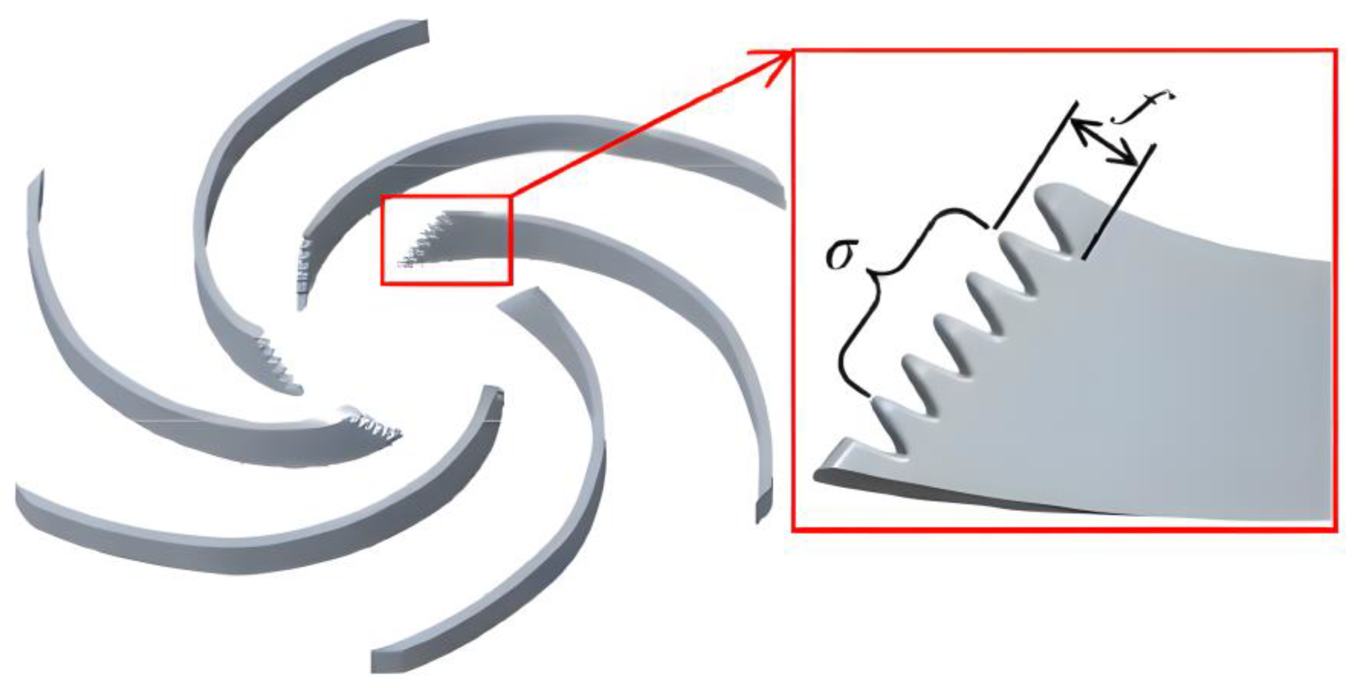
Humpback whales possess elevated nodules on their flippers, as seen in Figure 5. These nodules induce a swirling motion in the water, thus disrupting the flow pattern. This leads to a decrease in swimming resistance and an increase in buoyancy, a phenomenon that scientists have termed the ‘nodule effect’ [42]. Inspired by the ‘nodule effect’, scientists have modified the blade leading-edge design to prevent the occurrence of cavitation in the pump. Zhao et al. [43] developed a bionic vane for centrifugal pumps, inspired by the ‘nodule effect’ observed in humpback whales, as depicted in Figure 6. NPSHa is net positive suction head available. Figure 7 illustrates the cavity volume in the impeller channel under various NPSHa conditions during the fifth rotation cycle of the numerical simulation. The bionic model reduces the vacuole volume in the impeller channel without affecting the hydraulic performance of the prototype pump, particularly during the initial stage of cavitation. The average reduction in vacuole volume fraction was 99.72%. Furthermore, the bionic structure reduces pressure pulsation within the centrifugal pump, thereby diminishing cavitation noise and mitigating the surge phenomenon. Wang and colleagues [44] developed a bionic design for centrifugal pump blades inspired by the flipper of a humpback whale, as seen in Figure 8. Simulations revealed that the bionic vanes exhibited increased head at various operating points and a reduced cavitation formation rate under conditions of low cavitation margin. This suggests that the design of the pump may successfully prohibit cavitation and enhance its stability.
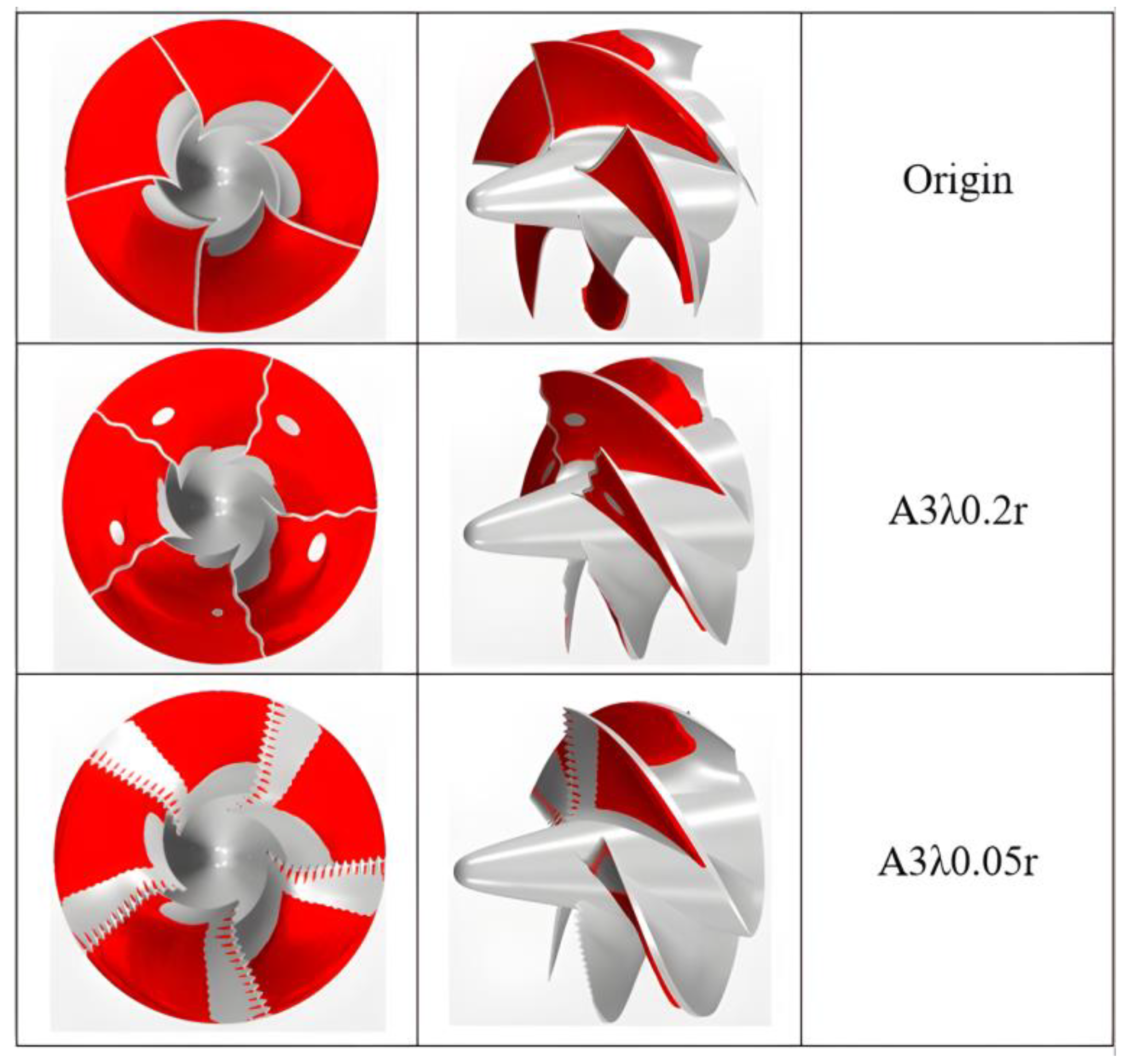
Li et al. [45] utilized sinusoidal tubercle trailing edge (STTE), a design inspired by the structure of humpback whale flippers, in low-specific-speed centrifugal pump vanes. They compared two vane designs: one featuring a conventional sharp-angle trailing edge (OTE) and the other utilizing STTE. The study revealed that the bionic waveform knotting design significantly reduced pressure pulsation and enhanced the hydraulic performance of the pump. The bionic knot effectively prevents cavitation by reducing the formation of leading-edge dissociating vortices and decreasing the size of U-shaped vortices. Inspired by the humpback whale flipper structure, Zhang et al. [46] developed a bionic knot at the leading edge of the blade. The results demonstrated that the bionic vane effectively reduced the volume of bubbles produced by cavitation, lowered the drag coefficient, and stabilized lift force fluctuations. Specifically, the bionic blade’s bubble volume percentage decreased by 9.67%, and the drag coefficient decreased by 9.36%. Xu et al. [47] investigated a propulsion pump and developed the first bionic propulsion pump. The physical configuration of the bionic impeller is shown in Figure 9. Convex joints facilitate the stable attachment of air bubbles, reinforcing the suppression of load-induced excitation forces. A comparison of the hydraulic performance between the bionic and prototype impellers revealed an efficiency loss of less than 2.5%, but a head improvement of up to 10%. Pump head and efficiency calculations are shown in Equations (1) and (2). Despite the presence of a moderately turbulent flow field on the surface layer of the bionic blade, cavitation formation is hindered, and vacuole erosion is limited. Additionally, leading-edge lugs help create a low-pressure zone in the trough, facilitating cavitation priming in the bionic pump [48]. Wang et al. [49] designed a non-smooth sinusoidal leading-edge bionic impeller, inspired by the nodules of the humpback whale flipper. They varied amplitude and wavelength to create different control groups. The parameters of the bionic leading edge are defined in Figure 10, where A represents the amplitude and κ represents the wavelength, measured in millimeters. The gas volume percentage for different bionic impeller parameters is shown in Figure 11. The analysis of the gas volume fraction diagram revealed that the A3μ0.05r configuration exhibited superior anti-cavitation capability. Additionally, the bionic blade with a shorter wavelength demonstrated better anti-cavitation performance, whereas the blade with a wavelength of 0.2r worsened cavitation. Therefore, the design characteristics of the bionic structure are crucial; a well-designed bionic structure can achieve optimal results, while a poorly designed one may have adverse effects. Research involving animals or humans, as well as other investigations requiring ethical approval, must include the granting authority and the relevant ethical approval code.
H = P t o u t P t i n ρ g = P o u t + ρ 2 ( Q S o u t ) 2 P i n + ρ 2 ( Q S i n ) 2 ρ g
η = ( P t o u t P t i n ) Q M ω
where H is the head of the pump; Ptin, Ptout are the total pressure values of the inlet and outlet, respectively; Pin, Pout is the static pressure values of the inlet and outlet, respectively; Sin, Sout are the areas of the inlet and outlet, respectively; ρ is the density of the medium; g is the acceleration of gravity; η is the efficiency of the pump for the nuclear coolant; Q is the volumetric flow rate; M is the effective torque; and ω is the rotational angular velocity.
To visually summarize the findings of the humpback whale fin-inspired research, Table 1 presents a comparison of the key literature and their optimization outcomes. As shown in the table, the humpback whale flippers inspired designs to demonstrate notable advantages in improving pump anti-cavitation performance. These biomimetic designs effectively mitigate cavitation and enhance both the hydraulic performance and stability of the pump. Furthermore, the incorporation of bionic tubercles not only reduces pressure pulsation but also significantly decreases cavitation volume and drag coefficient. This underscores the potential of leading-edge bionic structures for optimizing pump performance.
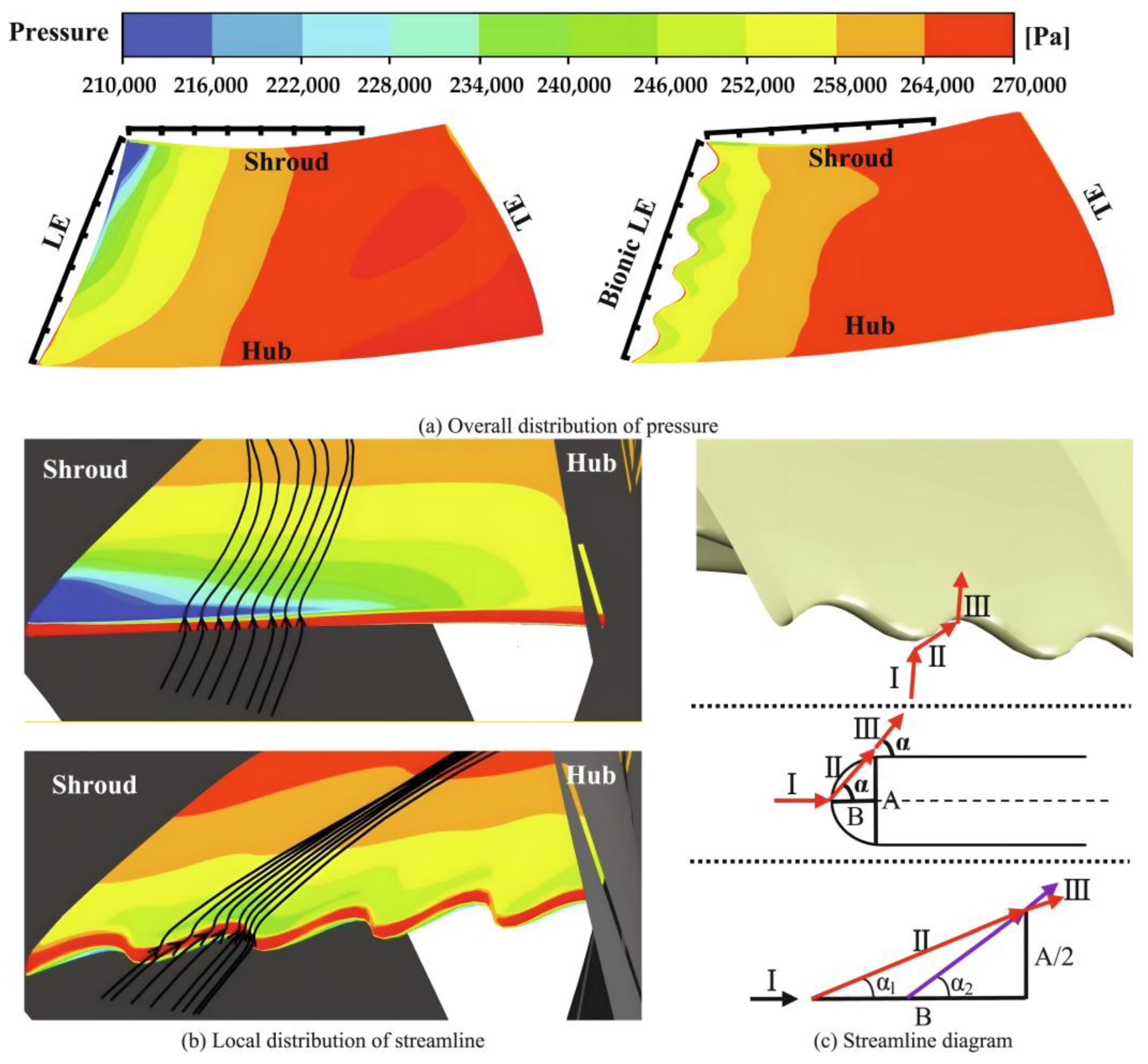
In addition to bionic humpback whale flipper nodules, other bionic leading-edge structures have also been studied. In their study, Liu et al. [50] were inspired by the silent and agile flight of owls to design bionic vanes for nuclear coolant pumps. The blade’s profile is divided into the pressure surface profile, suction surface profile, and camber line, as shown in Figure 12. Two variables characterize the blade’s leading edge: the distance from the leading section of the wavy line to the root, and the number of crests in the wavy line. These are described using parametric formulas in Publication 1. Figure 13 displays the numerical simulation results of altering the leading edge of the original blade based on the structure of owl feathers. The implementation of the bionic leading edge optimizes the low-pressure zone at the blade’s leading edge. This results in a change in the flow direction of the fluid passing through the blade. For the bionic LE, the incoming velocity would be changed near the leading edge wave. To make this clearer, the flow near the wavy structure was segmented into three processes, including the incoming flow (I), the spanwise flow (II), and surface flow (III) shown in Figure 13c. Specifically, the bionic leading edge at angle α1 is smaller than the original leading edge at angle α2, reducing the separation of the boundary layer. The bionic leading edge increases turbulent kinetic energy and improves performance by reducing pressure resistance in individual blade channels through boundary layer suppression.
γ l = C L l C L r e f
where C L l is the length of the camber line at the trough of the wave after leading-edge correction; C L r e f is the length of the camber line of the reference model.
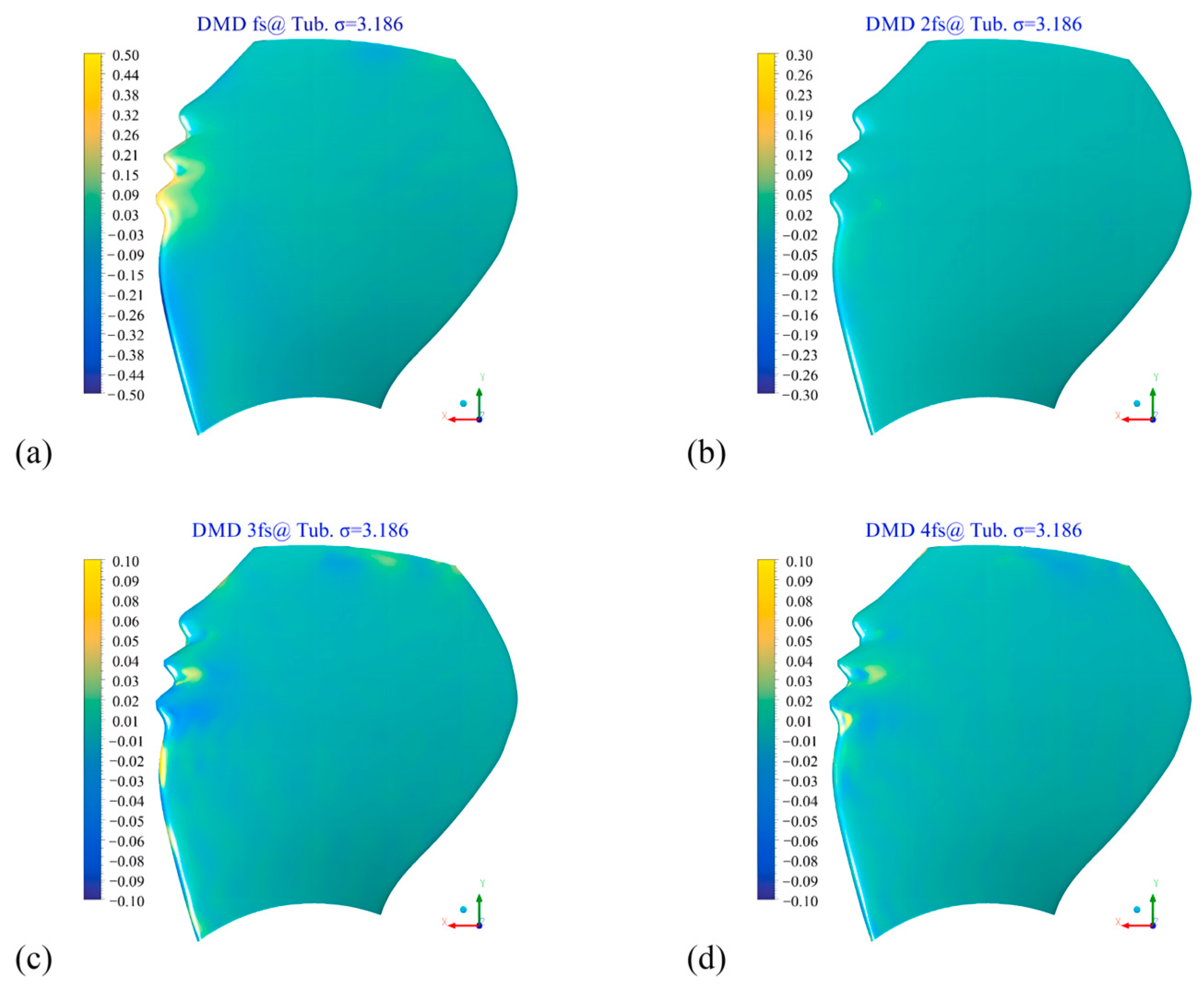
In Figure 14, Zhao [51] developed a bionic leading-edge modular impeller for a waterjet pump. The impeller incorporates a wave structure in the meridional plane of the original blade, with the maximum thickness and position of the cross-section between the peaks and valleys adjusted to ensure a smooth transition along the line. Using the dynamic modal decomposition (DMD) approach, the spatial load distribution of the nodal blade was analyzed. Figure 15 demonstrates that the oscillations related to the lobe frequency are mostly concentrated in the center of the blade, while the modal energy is nearly imperceptible at the leading edge in the 2× to 4× modes. The bionic leading-edge construction successfully mitigates the dynamic oscillations at the leading edge seen in the original blade, thus avoiding the consequences of significant load oscillations. Drawing on the biological prototype of Squilla shrimp and analyzing its cuticle and body spine structure, Zhang et al. [52] developed three types of biomimetic streamline structures: triangular groove, circular groove, and rectangular groove. These structures were applied to the impeller of a centrifugal pump and subjected to control tests. Experimental results indicated that the circular groove blades had the smallest low-pressure area and the highest resistance to cavitation. This demonstrates the excellent anti-cavitation capability of the circular groove design. Sturgeon, having evolved over hundreds of millions of years, has adapted its body structure to optimize underwater movement. Su et al. [53] utilized the curves of the sturgeon’s body to design a bionic wing. Without altering the pressure surface of the waterjet propulsion pump blade, they changed the blade’s cross-sectional geometry. The results verified that the bionic wing pump had the smallest cavitation margin, with the least amount of air bubbles on the blade surface, achieving the best anti-cavitation performance.

2.2. Bionic Shell Structure

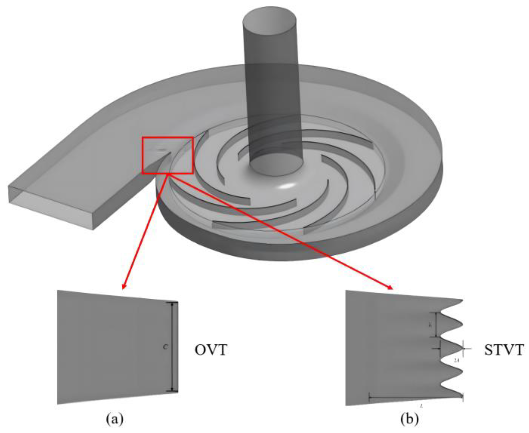
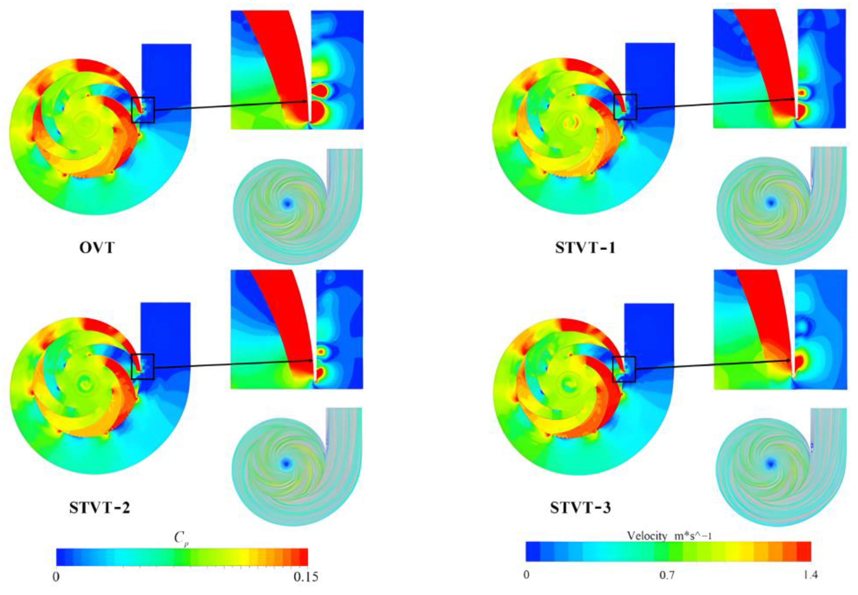
Cavitation phenomena are not limited to the leading edge of the blades but also manifest in the worm housing. Within the worm housing, the fluid flow velocity and pressure distribution exhibit non-uniformity. Specific regions, particularly those with significant fluid flow rates, may develop localized low-pressure zones. Cavitation may occur when the pressure in these areas drops below the vapor pressure of the fluid [54,55,56,57]. To enhance the anti-cavitation capabilities of a centrifugal pump, Lin et al. [58] developed a novel spacer tongue inspired by the anatomical features of the humpback whale flipper, as seen in Figure 16. This study aimed to examine the impact of three bionic spacer tongues, known as sinusoidal tubercle volute tongues (STVT), and one original spacer tongue (OVT) on energy dissipation. The energy dissipation formula is shown in Equation (4). Table 2 summarizes the time-averaged total entropy, energy dissipation reduction rate, and efficiency of both the original spacer tongue pump and the bionic spacer tongue pump. The data indicate that the bionic spacer tongue significantly decreases energy dissipation, with the STVT-3 spacer tongue achieving the greatest reduction of 10.01% and an efficiency enhancement of 2.1%. Through the analysis of pressure coefficient distribution in the spacer tongue region, as depicted in Figure 17, it is evident that STVT-1, STVT-2, and STVT-3 exhibit more homogeneous pressure coefficient distributions and fewer areas of high pressure. Notably, the pressure fluctuation in the spacer tongue region of STVT-3 is the least pronounced, and the influence of the rotor-stator interaction on this distribution is minimal. These findings indicate that the bionic spacer tongue has the potential to enhance the flow within the centrifugal pump, leading to a more consistent internal flow field structure and reduced pressure fluctuations.
Ω ( t ) = 1 2 ρ ω 2 d v
where ρ is the fluid density and ω is the flow vorticity.
The Nautilus is a cephalopod mostly found in the tropical Indian Ocean and Western Pacific coral reef environments and is sometimes referred to as a ‘marine living fossil’ organism. The Nautilus shell’s cross-sectional area gradually varies with the angle of rotation, as depicted in Figure 18. This gradual design enables precision control of fluid flow rate, preventing abrupt acceleration or deceleration, ensuring fluid pressure stability, and minimizing cavitation caused by pressure fluctuations. Wei and colleagues [59] introduced a biomimetic snail shell design inspired by the Nautilus shell. The gas–liquid two-phase distribution throughout the simulated liquid-filling process is depicted in Figure 19. From this figure, it is clear that the overall medium flow remains constant, and the flow state varies over time. The findings indicate that the flow field within the bionic worm shell is more uniform, resulting in a 78.95% reduction in energy loss.
In brief, the biomimetic leading-edge structure, inspired by the humpback whale flipper ‘nodule effect’, is a widely studied topic. This structure can significantly decrease the pressure pulsation on the blade surface, minimize the volume of bubbles produced by cavitation, and prevent subsequent cavitation. Furthermore, other leading-edge structures inspired by biological systems, such as the owl feather structure, have also shown exceptional resistance to cavitation. Manipulating the fluid flow inside the distinctive wave-type structure enhances the low-pressure zone located at the vane’s leading edge. This improvement not only enhances the pump’s anti-cavitation capabilities but also reduces noise. Moreover, the bionic design of the worm shell structure effectively mitigates cavitation by regulating fluid velocity fluctuations and improving vortex volume distribution and pressure density.

3. Bionic Surface Texture Design

By modifying the surface roughness, hydrophilicity, and other properties, it is possible to produce a bionic texture on the surface of a pump vane or worm casing that mimics the self-cleaning surfaces of sharks, dung beetles, and other natural organisms. This design may effectively prevent the formation and growth of cavitation bubbles. The shark epidermis is covered with uniform shield scales, which are organized in a roughly V-shaped bionic groove structure to efficiently minimize flow resistance. To develop a centrifugal pump model with V-groove surface blades, Dai et al. [60] extracted the surface characteristics of shark skin. Table 3 displays the average shear stress of smooth and bionic blades. The data indicate that the bionic surface blade exhibits effective drag reduction, achieving a maximum shear strain of 29.00%. The results suggest that the bionic surface can optimally regulate the fluid flow in the boundary layer adjacent to the vane wall and decrease the gradient of wall shear stress. The maximum drag reduction rate is 3.1%, the hydraulic efficiency increases by 2.06%, and the total sound pressure level decreases by 2.68%.
The dung beetle’s surface is not inherently smooth but instead exhibits several concave and convex features. This microstructure can mitigate the adhesion between the fluid and the surface, thereby decreasing fluid slip resistance. Consequently, this facilitates smoother fluid passage and minimizes the development of localized low-pressure zones. Utilizing the non-smooth structure of the dung beetle’s surface, Dai et al. [61] developed a biomimetic design that effectively increases the thickness of the boundary layer, reduces Reynolds stress on the blade surface, and thus reduces wall resistance and improves hydraulic efficiency. Concurrently, the rate of noise reduction is equivalent to the rate of drag reduction, suggesting that variation in shear stress can serve as a reliable indicator for both drag and noise reduction. Based on the non-smooth surface structure of the dung beetle, Gao [62] developed bionic vanes. The findings show that this bionic vane design significantly decreases flow resistance and noise in centrifugal pumps, thereby enhancing pump efficiency. Due to the distinctive microstructure of lizard skin, which positively influences fluid dynamics, the bionic design of the lizard’s surface texture may effectively prevent cavitation. Lizard skin has inherent hydrophobicity, a characteristic that can be replicated through bionic design. Enhanced surface hydrophobicity decreases the contact area between fluid and solid surfaces, thereby reducing fluid adhesion and flow resistance. Hydrophobic surfaces also inhibit the development and expansion of cavitation bubbles. Qian et al. [63] investigated the potential of a bionic erosion-resistant vane in a double-suction centrifugal pump to enhance the durability of the pump impeller in water-containing sand particles. The inspiration for this vane design was derived from the skin structure of desert lizards, which show exceptional resistance to erosion. The use of convex dome structures with varying heights on the impeller surface effectively mitigates erosion damage caused by high-speed sand-laden water flow. This reduction in erosion rate leads to an extended operational lifespan of the pump. By incorporating the convex structure of lizard skin into the impeller design of a double-suction centrifugal pump, as depicted in Figure 20, Dong et al. [64] examined how sediment properties affect sediment erosion characteristics of the pump and studied the corrosion resistance of the bionic raised top in reducing sediment erosion. Under most of the studied conditions, the bionic raised structure effectively alleviated sediment erosion by inducing the surrounding vortex flow, altering the relative water velocity on the blade surface, and decreasing the mass flow rate of sediment particles impacting the blade. This, in turn, reduced the erosion rate and erosion area of the blade. An analysis of the erosion resistance mechanism was conducted using large eddy simulation. The results indicated that the bionic elevated structure reduces sediment erosion. This finding offers a novel approach to building pump impellers with enhanced erosion resistance.
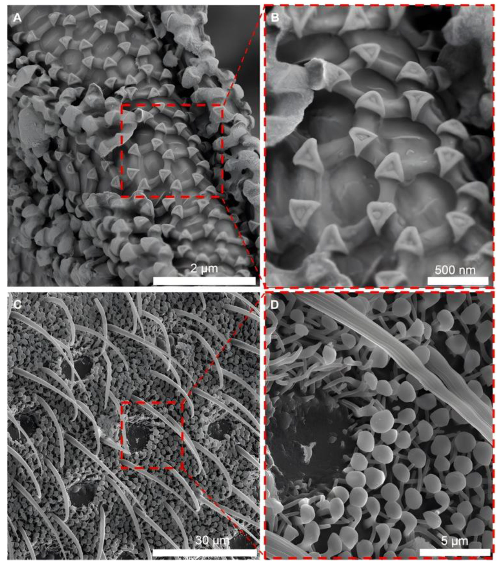
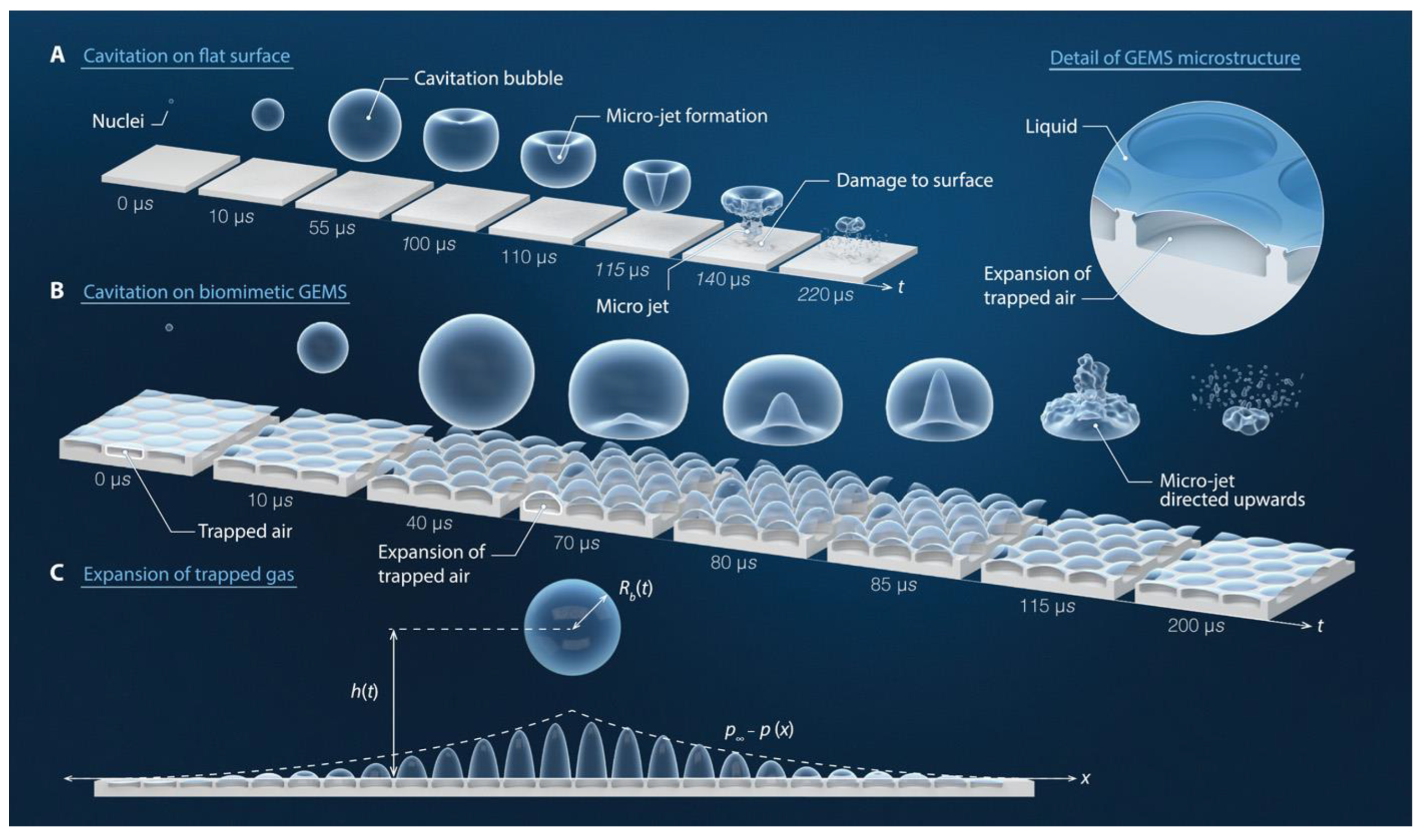
Both collembola and Halobates Germanus have developed specific drainage systems in response to their native environments. As seen in Figure 21, the cuticle of the collembola and the body hairs of Halobates Germanus consist of granules and mi-crosshairs, respectively. These structures resemble mushrooms and enable the insects to capture air in water for breathing, thus fulfilling a protective role [65,66,67,68]. A biomimetic gas-trapping-as-a-textured surface (GEMS) was developed by Gonzalez-Avila et al. [69]. In this system, the air inside the GEMS serves as a continuous ‘free’ boundary for cavitation bubbles, establishing a method to mitigate cavitation erosion. The presence of air within the GEMS creates continuous, undisturbed boundaries for cavitation bubbles, leading to an uncoated approach to counteract cavitation erosion. This is illustrated in Figure 22, where the bubbles within the GEMS effectively direct the cavitation bubbles away from the material’s surface, minimizing cavitation damage. This novel bionic texture design offers innovative solutions for addressing the cavitation phenomenon in pumps.
To optimize the anti-cavitation performance and operational stability of different types of pumps, bionic textures have been tailored to match the individual requirements of each pump under varied operating conditions. The use of refined bionic texturing significantly prolonged the operational lifespan of the pumps and enhanced their dependability. Zhao et al. [70] introduced a novel approach to managing cavitation by positioning a discontinuous elevated structure on the rear side of axial pump vanes. The enhanced blade design minimizes the low-pressure area at the blade’s rear and increases the high-pressure area at the working surface, lowering the critical cavitation margin and reducing the volume fraction of the vacuole, particularly during the early stages of cavitation. This results in a substantial inhibition of cavitation. Tian et al. [71] established a pit-type bionic non-smooth profile on the impeller and observed that this structure significantly reduces energy loss and enhances pump performance by lowering frictional resistance and turbulent viscosity on the impeller surface. In their study, Mou et al. [72] implemented a circular non-smooth surface structure on the suction surface of centrifugal pump blades using the bionics concept. By incorporating circular bumps of suitable diameter, they successfully reduced the low-pressure area in the impeller, increased the pressure gradient, and enhanced the turbulent kinetic energy at the suction surface of the blades near the wall. This design effectively inhibited cavitation. Ren et al. [73] investigated the bionic non-smooth surface processing of a centrifugal water pump impeller. Figure 23 illustrates the test results, which show that the bionic reshaped surface model greatly enhances efficiency within the effective working flow range. The maximum efficiency improvement observed was 3.45%, with a maximum increase of 6.81%. Peng [74] developed nine distinct bionic non-smooth impeller models, which were subsequently processed and tested, confirming that the bionic non-smooth surface significantly enhances pump efficiency. By arranging barriers on the surface of centrifugal pump blades, Zhao et al. [75] successfully increased the turbulent kinetic energy along the blade wall, altered the pressure distribution, and prevented cavitation at all stages of the centrifugal pump. During the cavitation development stage, the presence of obstacles improved the flow field structure and reduced vortex intensity near the back of the blade. These obstacles continuously decreased the vacuole volume, resulting in optimal flow field conditions.
In this chapter, the use and impact of bionic textures in pump anti-cavitation are examined. Through the utilization of microscopic surface texture structures found in sharks, dung beetles, lizards, and other organisms, a range of bionic textures were developed and subjected to comparative analysis. The findings indicate that these bionic designs not only successfully decrease flow resistance and noise but also impede the occurrence of cavitation, improving both the efficiency and longevity of the pump. Furthermore, the revolutionary GEMS bionic texture exhibits a distinct anti-cavitation mechanism compared to existing bionic textures by imitating the unique drainage patterns seen on the surfaces of elasmobranchs and seaweeds. By trapping the bubbles produced by cavitation and directing them to collapse away from the material surface, the texture reduces the erosion caused by cavitation, thus opening up a new avenue for the advancement of anti-cavitation technology.

4. Bionic Material

In recent years, researchers have progressively developed a range of new materials with specific functions by mimicking the material characteristics of living organisms in nature. These materials aim to decrease friction, achieve better wear resistance, and enhance corrosion resistance. Consequently, they extend the lifespan of the relevant devices and lower maintenance costs [76,77,78]. The utilization of biomimetic materials in the design and production of pumps also demonstrates its benefits. Bionic materials efficiently mitigate friction and turbulence in liquid flow by imitating the physical and chemical characteristics of natural organisms. This, in turn, reduces bubble collapse and impact damage inside the pump caused by cavitation events [79,80,81]. Moreover, the exceptional elasticity and hardness of these materials facilitate the absorption and dispersion of pressure variations, thereby significantly diminishing the likelihood of cavitation. Due to these characteristics, bionanomaterials have emerged as a potent tool for enhancing the safety and efficiency of pumps [82,83,84]. Currently, scientists are focused on advancing specialized bionanomaterials to enhance the physical architecture of pump surfaces and minimize issues like cavitation, which has become a prominent subject of study in this field.
According to Grossman [85], the fracture behavior of multiscale composites was examined by considering the biological characteristics of the nacreous layer found in mollusk shells. By employing a layered toughening technique, the energy needed to fracture the bionic material was enhanced, resulting in the development of layered composites that exhibit exceptional fracture resistance. A novel bionic coupled centrifugal pump (BCCP) was investigated by Tian [86,87] to enhance pump efficiency through the use of coupling theory. An effective simulation of the unique structure of a living organism’s skin was achieved by incorporating non-smooth features such as ribs and pits on the impeller of the centrifugal pump and covering it with polyurethane material. Experimental findings demonstrate that this design greatly enhances the pump’s efficiency and produces a more concentrated efficiency curve, indicating that the pump maintains a high level of efficiency even when it diverges from ideal operating conditions. Further investigation revealed that the enhanced effectiveness of the BCCP can be attributed to the elastic deformation of the polyurethane material. This characteristic enables the absorption of energy at elevated pressures and its subsequent gradual release, thus minimizing energy losses. Furthermore, the integration of the non-smooth configuration and the polyurethane material successfully stabilizes the flow inside the boundary layer of the pump impeller, thereby diminishing turbulence and friction and reducing the pump’s energy consumption. Superhydrophobic coatings are frequently cited as a bionic material technique for minimizing drag and noise in centrifugal pumps, drawing inspiration from the architecture of lotus leaves [88]. Figure 24 illustrates the surface morphology of superhydrophobic materials. The extremely high water contact angle produced by superhydrophobic coatings enables water droplets to form a near-perfect sphere on the coating surface by minimizing contact with the coating. Incorporating this coating onto critical pump components, such as impellers and worm casings, can greatly enhance pump performance and efficiency. The inherent self-cleaning properties of this coating also result in decreased maintenance costs and time, as particulate matter is less likely to adhere to the coated surface.
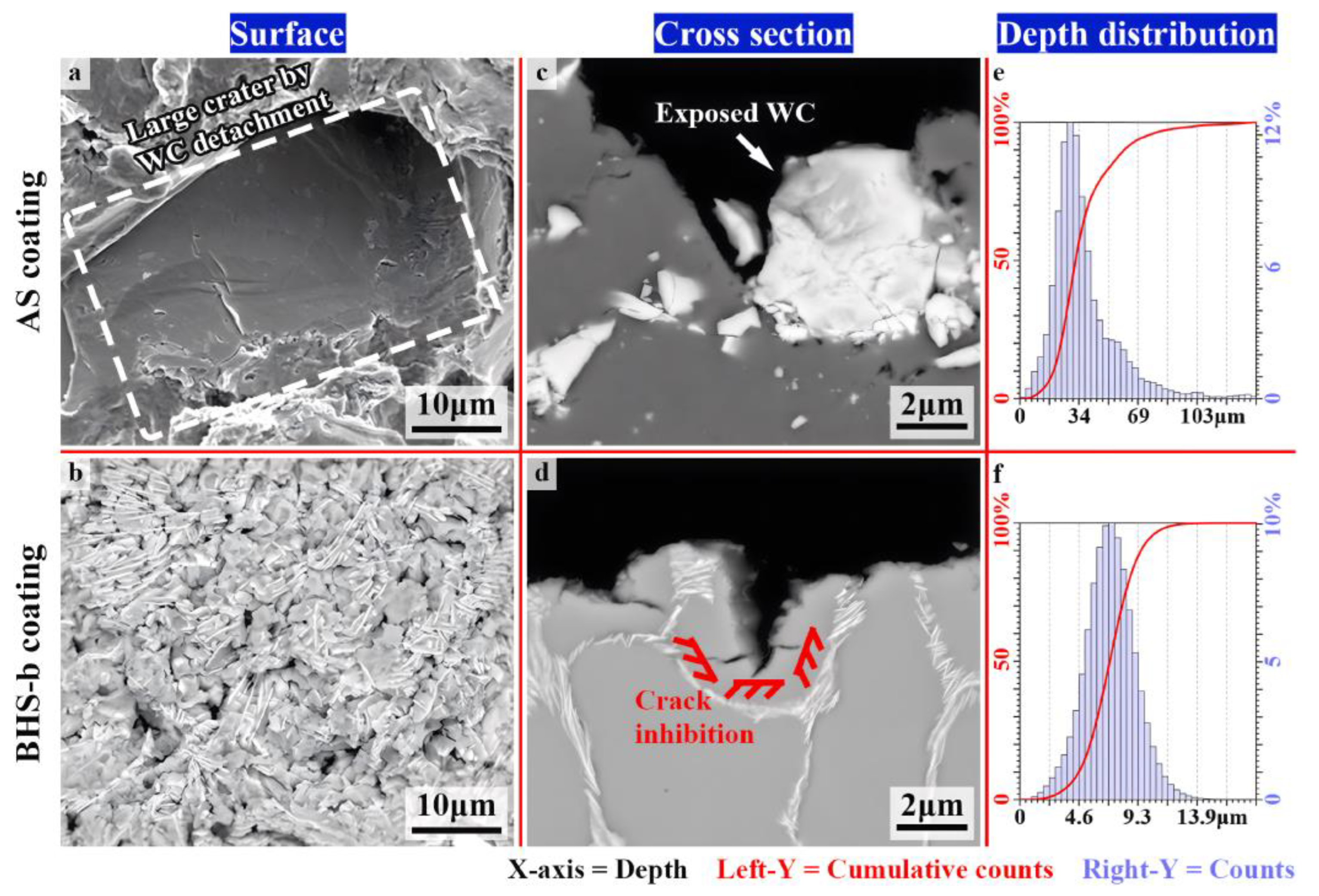
The development of bionic pearl-layer materials aims to enhance the strength and toughness of composites by replicating the microstructure of shell surfaces [89]. These materials are often manufactured in a ‘brick-mud’ configuration, which involves mixing a rigid inorganic substance with a pliable organic matrix to create a material that is resistant to impact and cavitation. Applying these materials to pump impellers and worm shells could greatly enhance their resistance to cavitation and mechanical wear. To enhance the structure of Ni-WC coating for impeller blade surfaces, Tian et al. [90] replicated the microstructure of cuttlefish and the nanoscale structure of shells. The layered architecture of the novel coating BHS-b is shown in Figure 25, featuring a fusion of two bionic components. The cellular architecture of cuttlefish bone undergoes a gradual and sequential breakdown when subjected to external pressure, thus avoiding immediate and total material failure. In contrast, the shell exhibits a sandwich structure that combines both soft and hard properties. This structure not only demonstrates extraordinary strength and toughness but also effectively reflects stress waves and distributes impact energy. These attributes are essential for materials that are resistant to cavitation. Experimental cavitation tests were conducted on the AS and BHS coatings, and the results are depicted in Figure 26. The surface of the BHS-b coating did not exhibit significant depressions. Additionally, the data on the depth of cavitation erosion show that the BHS-b coating did not display deep cavitation craters. This observation suggests that the BHS-b coating provides superior resistance to cavitation erosion.
Currently, several novel composite coatings have not yet been used in the rectification of pump cavitation. However, they offer new concepts and potential technical advancements to address this issue. Drawing inspiration from the dolphin skin’s resistance to elastic erosion and the gradient structure of bamboo pipe wall sections, Zhang [91] developed a novel anti-corrosion bionic elastic gradient functional surface. The bionic gradient coating comprises a buffer layer of 75% polyurethane and 25% silicone rubber. This coating absorbs scouring forces through the buffer layer, providing exceptional resistance to scouring and erosion. Additionally, it partially prevents corrosion caused by cavitation. Shao et al. [92] proposed composites combining bionic gradient layering and a Bouligand structure (GB). In this approach, nano-alumina was extruded in kaolin slurry, and by adjusting the printing settings, the thin strips of each layer were organized to create a composite GB structural framework. The bionic composites were synthesized through the sintering of the skeletal embryo, followed by polymer infiltration. The GB composites consist of a compact ceramic surface layer that directly withstands impact forces, along with a durable polymer-based base layer that optimizes the attenuation of residual impact energy.
The advancement in the use of bionic materials for pump anti-cavitation is detailed in this chapter. Bionic materials primarily apply to pumps as coatings, including bionic gradient and superhydrophobic coatings. By utilizing the robust elasticity and toughness of these materials, along with their drag-reducing properties, pressure is effectively absorbed and dispersed, preventing cavitation and minimizing energy loss in the pump. Enhancing the anti-cavitation efficacy of composite coatings can be achieved through the strategic layering and integration of various biological components. Although there are currently limited studies on anti-cavitation bionic coatings, these materials can serve as a valuable reference for further research in this field.

5. Conclusions

This paper presents an overview of recent advancements in bionic technology for pump anti-cavitation. It covers various types of bionic technologies, their principles, and specific applications in pumps. It also provides a detailed explanation of the bionic structure of overflow components, bionic texture design, and bionic materials used in pump anti-cavitation. The study further considers the practical requirements of bionic technology and offers key conclusions about its future development direction.
(1)
The application of bionic structures in pump overflow components has proven effective in reducing cavitation. These structures include blade leading-edge bionic structures and bionic worm shell structures. The blade leading-edge bionic structure, inspired by humpback whale flippers and owl feathers, prevents cavitation by imitating elevated nodules and streamlined shapes. This is achieved by controlling the surface flow field of the blade, reducing the size of leading-edge separating vortices and U-shaped vortices. Additionally, the structure reduces pressure pulsations and bubble volume. The design of a bionic snail shell, inspired by the nautilus shell, optimizes the septum tongue and linear elements, promotes pressure distribution, and increases the stability of the internal flow field, contributing to the suppression of cavitation. Modifying the blade leading-edge structure has become a common approach to preventing pump cavitation due to the reduced cost of impeller design and the simplified optimization process. In the future, optimizing the parameters of bionic geometry will likely be the most effective approach to enhance the pump’s anti-cavitation performance.
(2)
Bionic surface textures, inspired by the distinct microstructures seen in shark skin, dung beetles, and lizards, have demonstrated several advantageous properties. These designs efficiently regulate the flow of the boundary layer near the wall, thereby decreasing shear stresses and flow resistance associated with the wall, thus preventing cavitation and noise. A novel advancement in this field is biomimetic gas-entrapping microtextured surfaces (GEMSs), which draw inspiration from the unique waterproof structures found in the poplar tail fish and the Chinese seaworm. GEMSs effectively mitigate cavitation erosion by capturing cavitation bubbles and redirecting them away from the material’s surface, preventing their rupture. This development introduces a fresh avenue for exploring biomimetic microtexturing further. Although designing biomimetic textures is challenging, their exceptional resistance to cavitation makes the micrometer and nanometer scale a promising field for future research.
(3)
Novel anti-cavitation biomimetic coatings have been developed based on the properties of biological materials. These coatings include high-strength gradient coatings mimicking shells and super-hydrophobic coatings inspired by lotus leaves. These coatings effectively prevent cavitation by reducing friction and enhancing wear and corrosion resistance. The application of composite biomimetic materials on blade surfaces has emerged as a novel area of investigation for achieving anti-cavitation effects. Nevertheless, the limited use of bionic materials might be attributed to the high costs associated with research and development. In the future, enhancements in the durability and performance of these coatings will be achieved through optimization of their formulation and processing techniques. Additionally, the emergence of novel bionic materials will drive the advancement of anti-cavitation technology, offering promising prospects.

Author Contributions

Conceptualization, J.L., L.M. and P.Z.; Methodology, J.L.; Data curation, J.L., X.Z. and H.Z. Validation, J.L., L.M. and L.S.; Investigation, J.L. and X.Z.; Software, H.Z.; Resources, H.Z. and L.S.; Formal analysis, X.Z. and C.M.; Project administration, C.M.; Funding acquisition, J.L., L.M. and P.Z.; Writing—original draft preparation, J.L., H.Z. and X.Z.; Writing—review and Editing, L.M. and P.Z.; Supervision, C.M., L.S. and P.Z. All authors have read and agreed to the published version of the manuscript.

Funding

The authors gratefully acknowledge the financial support given by the IWHR Research &Development Support Program, grant number No. HM0145B012021, the Open Research Fund of Key Laboratory of River Basin Digital Twinning of Ministry of Water Resources, grant number No. Z0202042022, Fundamental Research Funds for the Provincial Universities of Zhejiang, grant number No. 2023YW98, the Zhejiang University Student Science and Technology Innovation Program, and the New Seedling Talent Program Project, grant number No. 2024R409037.

Conflicts of Interest

The authors declare no conflicts of interest, financial or otherwise.

References

  1. Kadivar, E.; Timoshevskiy, M.V.; Nichik, M.Y.; Moctar, O.E.; Schellin, T.E.; Pervunin, K.S. Control of Unsteady Partial Cavitation and Cloud Cavitation in Marine Engineering and Hydraulic Systems. Phys. Fluids 2020, 32, 052108. [Google Scholar] [CrossRef]
  2. Vokhidov, O.F.; Nazarov, B.U.; Rayimova, I. Influence of Cavitation-hydro Abrasive Wear and Wear of Vane Hydraulic Machines on the Hydraulic Resistance of the Suction Line of Pumping Units. AIP Conf. Proc. 2023, 2612, 020024. [Google Scholar]
  3. Benigni, H. Cavitation in Hydraulic Machines: Measurement, Numerical Simulation and Damage Patterns. In Proceedings of the ASME 2020 Fluids Engineering Division Summer Meeting Collocated with the ASME 2020 Heat Transfer Summer Conference and the ASME 2020 18th International Conference on Nanochannels, Microchannels, and Minichannels, Virtual, 13–15 July 2020; American Society of Mechanical Engineers Digital Collection: New York, NY, USA, 2020. [Google Scholar]
  4. Brennen, C.E. Cavitation in Medicine. Interface Focus 2015, 5, 20150022. [Google Scholar] [CrossRef] [PubMed]
  5. Zhang, Y.; Zhang, Y.; Wu, Y. A review of rotating stall in reversible pump turbine. Proc. Inst. Mech. Eng. Part C J. Mech. Eng. Sci. 2017, 231, 1181–1204. [Google Scholar] [CrossRef]
  6. Cravero, C.; Marsano, D.; Sishtla, V.; Halbe, C.; Cousins, W.T. Numerical investigations of near surge operating conditions in a two-stage radial compressor with refrigerant gas. J. Eng. Gas Turbines Power 2024, 146, 021010. [Google Scholar] [CrossRef]
  7. Čdina, M. Detection of Cavitation Phenomenon in a Centrifugal Pump Using Audible Sound. Mech. Syst. Signal Process. 2003, 17, 1335–1347. [Google Scholar] [CrossRef]
  8. Wu, D.; Ren, Y.; Mou, J.; Gu, Y.; Jiang, L. Unsteady Flow and Structural Behaviors of Centrifugal Pump under Cavitation Conditions. Chin. J. Mech. Eng. 2019, 32, 17. [Google Scholar] [CrossRef]
  9. Lu, J.; Yuan, S.; Luo, Y.; Yuan, J.; Zhou, B.; Sun, H. Numerical and Experimental Investigation on the Development of Cavitation in a Centrifugal pump. Proc. Inst. Mech. Eng. Part E-J. Process Mech. Eng. 2016, 230, 171–182. [Google Scholar] [CrossRef]
  10. Kan, K.; Binama, M.; Chen, H.; Zheng, Y.; Zhou, D.; Su, W.; Muhirwa, A. Pump as Turbine Cavitation Performance for Both Conventional and Reverse Operating Modes: A review. Renew. Sustain. Energy Rev. 2022, 168, 112786. [Google Scholar] [CrossRef]
  11. Li, Y.; Feng, G.; Li, X.; Si, Q.; Zhu, Z. An Experimental Study on the Cavitation Vibration Characteristics of a Centrifugal Pump at Normal Flow Rate. J. Mech. Sci. Technol. 2018, 32, 4711–4720. [Google Scholar] [CrossRef]
  12. Schiavello, B.; Visser, F.C. Pump Cavitation: Various NPSHR Criteria, NPSHA Margins, Impeller Life Expectancy. In Proceedings of the 25th International Pump Users Symposium, Houston, TX, USA, 23–26 February 2009; Texas A&M University, Turbomachinery Laboratories: College Station, TX, USA, 2009. [Google Scholar]
  13. Al-Obaidi, A.R. Investigation of Effect of Pump Rotational Speed on Performance and Detection of Cavitation within a Centrifugal Pump Using Vibration Analysis. Heliyon 2019, 5, e01910. [Google Scholar] [CrossRef] [PubMed]
  14. Friedrichs, J.; Kosyna, G. Rotating Cavitation in a Centrifugal Pump Impeller of Low Specific Speed. J. Fluids Eng. 2002, 124, 356–362. [Google Scholar] [CrossRef]
  15. Orlandi, F.; Montorsi, L.; Milani, M. Cavitation Analysis through CFD in Industrial Pumps: A review. Int. J. Thermofluids 2023, 20, 100506. [Google Scholar] [CrossRef]
  16. Homa, D.; Wróblewski, W. Modelling of Flow with Cavitation in Centrifugal Pump. J. Phys. Conf. Ser. 2014, 530, 012032. [Google Scholar] [CrossRef]
  17. Zhu, H.; Qiu, N.; Wang, C.; Si, Q.; Wu, J.; Deng, F.; Liu, X. Prediction of Cavitation Evolution and Cavitation Erosion on Centrifugal Pump Blades by the DCM-RNG Method. Scanning 2021, 2021, 6498451. [Google Scholar] [CrossRef] [PubMed]
  18. Zhang, K.; Li, J.; Gao, Z.; Zhang, B. Design and Performance Evaluation of Bionics-based Combined Blade for Horizontal Axis Tidal Current Hydro-turbine. J. Renew. Sustain. Energy 2022, 14, 054501. [Google Scholar] [CrossRef]
  19. Wang, K.; Ju, Y.; Zhang, C. A Quantitative Evaluation Method for Impeller-Volute Tongue Interaction and Application to Squirrel Cage Fan with Bionic Volute Tongue. J. Fluids Eng. 2019, 141, 081104. [Google Scholar] [CrossRef]
  20. Yan, H.; Zhang, H.; Wang, J.; Song, T.; Qi, F. The Leading-Edge Structure Based on Geometric Bionics Affects the Transient Cavitating Flow and Vortex Evolution of Hydrofoils. Front. Energy Res. 2022, 9, 821925. [Google Scholar] [CrossRef]
  21. Dai, C.; Guo, C.; Chen, Y.; Dong, L.; Liu, H. Analysis of the Influence of Different Bionic Structures on the Noise Reduction Performance of the Centrifugal Pump. Sensors 2021, 21, 886. [Google Scholar] [CrossRef]
  22. Lin, Y.; Li, X.; Zhu, Z.; Wang, X.; Lin, T.; Cao, H. An Energy Consumption Improvement Method for Centrifugal Pump Based on Bionic Optimization of Blade Trailing Edge. Energy 2022, 246, 123323. [Google Scholar] [CrossRef]
  23. Iannetti, A. A Numerical and Experimental Study on Cavitation in Positive Displacement Pumps and Its Application in Valve Design Optimization. Ph.D. Thesis, University of Strathclyde, Glasgow, UK, 2015. [Google Scholar]
  24. Calimanescu, I.; Stan, L.-C. Optimization Study of a Centrifugal Pump in Cavitation. In Advanced Topics in Optoelectronics, Microelectronics and Nanotechnologies X; SPIE-Int Soc Optical Engineering: Bellingham, UK, 2020; Volume 11718, pp. 471–480. [Google Scholar]
  25. Škerlavaj, A.; Titzschkau, M.; Pavlin, R.; Vehar, F.; Mežnar, P.; Lipej, A. Cavitation Improvement of Double Suction Centrifugal Pump HPP Fuhren. IOP Conf. Ser. Earth Environ. Sci. 2012, 15, 022009. [Google Scholar] [CrossRef]
  26. Niazi, E.; Mahjoob, M.J.; Bangian, A. Experimental and Numerical Study of Cavitation in Centrifugal Pumps. In Proceedings of the ASME 2010 10th Biennial Conference on Engineering Systems Design and Analysis, Istanbul, Turkey, 12–14 July 2010; American Society of Mechanical Engineers Digital Collection: New York, NY, USA, 2010; pp. 395–400. [Google Scholar]
  27. Mousmoulis, G.; Anagnostopoulos, J.; Papantonis, D. A Review of Experimental Detection Methods of Cavitation in Centrifugal Pumps and Inducers. Int. J. Fluid Mach. Syst. 2019, 12, 71–88. [Google Scholar] [CrossRef]
  28. Mousmoulis, G.; Karlsen-Davies, N.; Aggidis, G.; Anagnostopoulos, J.; Papantonis, D. Experimental Analysis of the Onset and Development of Cavitation in a Centrifugal Pump. J. Phys. Conf. Ser. 2017, 813, 012044. [Google Scholar] [CrossRef]
  29. McCaul, C. An Advanced Cavitation Resistant Austenitic Stainless Steel for Pumps. In Proceedings of the CORROSION 96, Denver, CO, USA, 24–29 March 1996; OnePetro: Richardson, TX, USA, 1996. [Google Scholar]
  30. Kesba, O.K.; Mihoubi, M.K.; Bourkia, M. Study of the Effect of Cavitation upon the Wheels of Different Types of Materials for Pump. Mech. Ind. 2013, 14, 299–304. [Google Scholar] [CrossRef]
  31. Noon, A.A.; Jabbar, A.U.; Koten, H.; Kim, M.; Ahmed, H.W.; Mueed, U.; Shoukat, A.A.; Anwar, B. Strive to Reduce Slurry Erosion and Cavitation in Pumps through Flow Modifications, Design Optimization and Some Other Techniques: Long Term Impact on Process Industry. Materials 2021, 14, 521. [Google Scholar] [CrossRef] [PubMed]
  32. Pawel, S.J. Assessment of Cavitation-Erosion Resistance of Potential Pump Impeller Materials for Mercury Service at the Spallation Neutron Source: ORNL/TM-2007/033; Oak Ridge National Lab. (ORNL): Oak Ridge, TN, USA, 2007. [Google Scholar]
  33. Qiu, N.; Wang, L.; Wu, S.; Likhachev, D.S. Research on cavitation erosion and wear resistance performance of coatings. Eng. Fail. Anal. 2015, 55, 208–223. [Google Scholar] [CrossRef]
  34. Liu, H.; Cao, M.; Chen, J.; Wang, Y.; Wang, C. Experimental Study on Abrasion and Cavitation Resistance of Non-Metallic Coating Materials for Pump. In Proceedings of the ASME-JSME-KSME 2019 8th Joint Fluids Engineering Conference, San Francisco, CA, USA, 28 July–1 August 2019; American Society of Mechanical Engineers Digital Collection: New York, NY, USA, 2019. [Google Scholar]
  35. Steller, J.; Krella, A.; Koronowicz, J.; Janicki, W. Towards Quantitative Assessment of Material Resistance to Cavitation Erosion. Wear 2005, 258, 604–613. [Google Scholar] [CrossRef]
  36. Li, X.; Yuan, S.; Pan, Z.; Yuan, J.; Fu, Y. Numerical Simulation of Leading-edge Cavitation within the Whole Flow Passage of a Centrifugal Pump. Sci. China Technol. Sci. 2013, 56, 2156–2162. [Google Scholar] [CrossRef]
  37. Hirschi, R.; Dupont Ph Avellan, F.; Favre, J.; Guelich, J.; Parkinson, E. Centrifugal Pump Performance Drop Due to Leading-edge Cavitation: Numerical Predictions Compared with Model Tests. J. Fluids Eng. 1998, 120, 705–711. [Google Scholar] [CrossRef]
  38. Tao, R.; Xiao, R.; Wang, Z. Influence of Blade Leading-Edge Shape on Cavitation in a Centrifugal Pump Impeller. Energies 2018, 11, 2588. [Google Scholar] [CrossRef]
  39. Balasubramanian, R.; Bradshaw, S.; Sabini, E. Influence of Impeller Leading-edge Profiles on Cavitation and Suction Performance. In Proceedings of the Middle East Turbomachinery Symposia. 2013 Proceedings, QA, DOH, QA, DOH, Paphos, Cyprus, 17 March–20 March 2013; Turbomachinery Laboratory, Texas A&M Engineering Experiment Station: College Station, TX, USA, 2013. [Google Scholar]
  40. Arabnejad, M.H.; Amini, A.; Farhat, M.; Bensow, R.E. Numerical and Experimental Investigation of Shedding Mechanisms from Leading-edge Cavitation. Int. J. Multiph. Flow 2019, 119, 123–143. [Google Scholar] [CrossRef]
  41. Zheng, H.W.; Liu, J.; Lai, G.H.; Zeng, Y.S.; Yao, Z.F. Application of Different Turbulence Models to Numerical simulation of Hydrofoil Cavitating Flow Field. J. Northeast Electr. Power Univ. 2021, 41, 43–52. (In Chinese) [Google Scholar]
  42. Fish, F.E.; Battle, J.M. Hydrodynamic Design of the Humpback Whale Flipper. J. Morphol. 1995, 225, 51–60. [Google Scholar] [CrossRef] [PubMed]
  43. Zhao, W.G.; Qin, J.W.; Tian, X.F.; Tian, X.F.; Wen, T.M. Cavitation Characteristics of Bionic Centrifugal Pump Based on “Nodule Effect” of Humpback Whale. Trans. Chin. Soc. Agric. Eng. (Trans. CSAE) 2022, 38, 23–31. (In Chinese) [Google Scholar]
  44. Wang, L.K.; Liang, C.; Luo, X.Q.; Xie, H.; Zhu, G.J.; Feng, J.J.; Li, C.H. Numerical Investigation of Cavitation Suppression of Centrifugal Pump Based on the Bionic Humpback Whale Blade. J. Phys. Conf. Ser. 2024, 2752, 012126. [Google Scholar] [CrossRef]
  45. Li, B.; Li, X.; Jia, X.; Chen, F.; Fang, H. The Role of Blade Sinusoidal Tubercle Trailing Edge in a Centrifugal Pump with Low Specific Speed. Processes 2019, 7, 625. [Google Scholar] [CrossRef]
  46. Zhang, J.; Liu, S.; Yan, Q.; Khoo, B.C.; Liu, C.; Guo, M.; Wei, W. Numerical and Experimental Analysis of Biomimetic Tubercle for Cavitation Suppression in Viscous Oil Flow around Hydrofoil. Eng. Appl. Comput. Fluid Mech. 2024, 18, 2394176. [Google Scholar] [CrossRef]
  47. Xu, K.L.; Bai, T.C.; Wu, F.L.; Xia, L.S.; Zhao, G.T.; Cao, L.L.; Qin, S.J.; Wu, D.Z. Blade Cavitation Control by Leading-Edge Tubercles in Water Jet Pump. J. Propuls. Technol. 2022, 43, 210534. (In Chinese) [Google Scholar]
  48. Xu, K.L. Study on the Cavitation Control Mechanism of Leading-Edge Tubercles in Axial-Flow Pump Blade. Master’s Thesis, Zhejiang University, Hangzhou, China, 2023. (In Chinese). [Google Scholar]
  49. Wang, J.Q.; Wan, C.R.; Zhou, M.; Wang, Z.L.; Yang, M.Z. Investigations on Cavitation Suppression of Bionic Water-jet Impeller. J. Phys. Conf. Ser. 2024, 2707, 012147. [Google Scholar] [CrossRef]
  50. Liu, H.; Lu, Y.; Wang, X.; Li, Y.; Yan, Y.; Lai, X. Investigation of the Effects of the Vane Blades on the CAP1400 Nuclear Coolant Pump’s Performance Based on a Bionic Strategy. Nucl. Eng. Des. 2021, 384, 111465. [Google Scholar] [CrossRef]
  51. Zhao, G.; Liang, N.; Li, Q.; Cao, L.; Wu, D. Effect Mechanisms of Leading-edge Tubercle on Blade Cavitation Control in a Waterjet Pump. Ocean Eng. 2023, 290, 116240. [Google Scholar] [CrossRef]
  52. Zhang, Z.C.; Dai, Y.; Gu, Y.Q.; Shi, Z.; Mou, J. Effect of Bionic Groove Surface Blade on Cavitation Characteristics of Centrifugal Pump. In Proceedings of the ASME-JSME-KSME 2019 8th Joint Fluids Engineering Conference, San Francisco, CA, USA, 28 July–1 August 2019; Fluid Mechanics. ASME: New York, NY, USA, 2019; Volume 1, pp. 1–8. [Google Scholar]
  53. Su, X.Z.; Li, W.J.; Xie, W.C.; Song, f.; Chang, H.; Wang, L. Cavitation Characteristics of Impeller of Water Jet Propulsion Pumps Based on Bionic Airfoil. J. Qingdao Agric. Univ. (Nat. Sci.) 2022, 39, 147–152. (In Chinese) [Google Scholar]
  54. Zhu, Y.; Zhou, L.; Lv, S.; Shi, W.D.; Ni, H.J.; Li, X.Y.; Tao, C.Z.; Hou, Z.J. Research Progress on Identification and Suppression Methods for Monitoring the Cavitation State of Centrifugal Pumps. Water 2024, 16, 52. [Google Scholar] [CrossRef]
  55. Rao, Z.; Tang, L.; Zhang, H. Double-Tongue Worm Shell Structure on Plastic Centrifugal Pump Performance Study. Appl. Sci. 2023, 13, 8507. [Google Scholar] [CrossRef]
  56. Wang, J.; Sun, L.; Zhou, Y.; Liu, Y.; Zhao, F. Numerical Simulation of Cavitation Characteristics of a Centrifugal Pump Based on an Improved ZGB Model. Processes 2023, 11, 438. [Google Scholar] [CrossRef]
  57. Wang, X.; Zhang, J.; Li, Z. Numerical Simulation of Internal Flow Field of Self-Designed Centrifugal Pump. J. Phys. Conf. Ser. 2021, 2097, 012017. [Google Scholar] [CrossRef]
  58. Lin, P.; Wang, C.; Song, P.; Li, X. Analysis of the Energy Loss and Performance Characteristics in a Centrifugal Pump Based on Sinusoidal Tubercle Volute Tongue. Entropy 2023, 25, 545. [Google Scholar] [CrossRef]
  59. Wei, W.; Tao, T.; Si, L.; Wang, G.; Yan, Q. Design and Optimization of Bionic Nautilus Volute for a Hydrodynamic Retarder. Eng. Appl. Comput. Fluid Mech. 2023, 17, 2273391. [Google Scholar] [CrossRef]
  60. Dai, C.; Ge, Z.P.; Dong, L.; Liu, H. Research on Characteristics of Drag Reduction and Noise Reduction on V-groove Surface of Bionic Blade of Centrifugal Pump. Huazhong Univ. Sci. Tech. (Nat. Sci. Ed.) 2020, 48, 113–118. (In Chinese) [Google Scholar]
  61. Dai, C.; Guo, C.; Ge, Z.; Liu, H.; Dong, L. Study on Drag and Noise Reduction of Bionic Blade of Centrifugal Pump and Mechanism. J. Bionic Eng. 2021, 18, 428–440. [Google Scholar] [CrossRef]
  62. Ge, Z.P. Research on Drag Reduction and Noise Reduction Characteristics of Bionic Blades of Centrifugal Pump Based on Massive Parallel Grid. Ph.D. Thesis, Jiangsu University, Zhenjiang, China, 2020. (In Chinese). [Google Scholar]
  63. Qian, Z.D.; Dong, J.; Guo, Z.W.; Wang, Z.Y.; Wang, F. Study of a Bionic Anti-Erosion Bladeina Double Suction Centrifugal Pump; American Society of Mechanical Engineers: Washington, DC, USA, 2016. [Google Scholar]
  64. Dong, J.; Qian, Z.; Thapa, B.S.; Thapa, B.; Guo, Z. Alternative Design of Double-Suction Centrifugal Pump to Reduce the Effects of Silt Erosion. Energies 2019, 12, 158. [Google Scholar] [CrossRef]
  65. Hensel, R.; Neinhuis, C.; Werner, C. The Springtail Cuticle as a Blueprint for Omniphobic Surfaces. Chem. Soc. Rev. 2016, 45, 323–341. [Google Scholar] [CrossRef] [PubMed]
  66. Nickerl, J.; Helbig, R.; Schulz, H.-J.; Werner, C.; Neinhuis, C. Diversity and Potential Correlations to the Function of Collembola Cuticle Structures. Zoomorphology 2013, 132, 183–195. [Google Scholar] [CrossRef]
  67. Cheng, L. Biology of Halobates (Heteroptera: Gerridae). Ann. Rev. Entomol. 1985, 30, 111–135. [Google Scholar] [CrossRef]
  68. Cheng, L. Marine and Freshwater Skaters: Differences in Surface Fine Structures. Nature 1973, 242, 132–133. [Google Scholar] [CrossRef]
  69. Gonzalez-Avila, S.R.; Nguyen, D.M.; Arunachalam, S.; Domingues, E.M.; Mishra, H.; Ohl, C. Mitigating Cavitation Erosion Using Biomimetic Gas-entrapping MiCrotextured Surfaces (GEMS). Sci. Adv. 2020, 6, eaax6192. [Google Scholar] [CrossRef]
  70. Zhao, W.G.; Zhao, F.R.; Lu, J.J. Study on the Control of Cavitation of Axial Flow Pump with Discontinuous Bulges on the Back of Blades. J. Eng. Thermophys. 2021, 42, 96–105. (In Chinese) [Google Scholar]
  71. Tian, L.M.; Ren, L.Q.; Peng, Z.Y. Numerical Simulation of Efficiency and Energy Saving Characteristics of Bionic Non-Smooth Centrifugal Water Pumps; China Agricultural Machinery Association: Jilin, China, 2008; p. 5. (In Chinese) [Google Scholar]
  72. Mou, J.G.; Zhang, Z.C.; Gu, Y.Q.; Shi, D.Z.; Zheng, S.H. Effect of Circular Non-Smooth Surface Blades on Cavitation Characteristics of Centrifugal Pump. J. Shanghai Jiao Tong Univ. 2020, 54, 577–583. (In Chinese) [Google Scholar]
  73. Ren, L.Q.; Peng, Z.Y.; Chen, Q.H.; Zhao, G.R.; Wang, T.J. Experi Mental Study on Efficiency Enhancement of Centrifugal Water Pump by Bionic Non-smooth Technique. J. Jilin Univ. (Eng. Technol. Ed.) 2007, 37, 575–581. (In Chinese) [Google Scholar]
  74. Peng, Z.Y. Research on Bionic Non-Smooth Increased Efficiency of Centrifugal Water Pump. Master’s Thesis, Jilin University, Changchun, China, 2006. (In Chinese). [Google Scholar]
  75. Zhao, W.G.; Zhao, G.S.; Xian, L.X.; Zhao, X.D. Effect of Surface-fitted Obstacle in Centrifugal Pump on Cavitation Suppression. J. Agric. Mach. 2017, 48, 111–120. (In Chinese) [Google Scholar]
  76. Zhang, X.; Xie, J.; Chen, J.; Okabe, Y.; Pan, L.; Xu, M. The Beetle Elytron Plate: A Lightweight, High-strength and Buffering Functional-structural Bionic Material. Sci. Rep. 2017, 7, 4440. [Google Scholar] [CrossRef] [PubMed]
  77. Yang, W.; Zhou, F.; Chen, X.; Zhang, Y. Performance Analysis of Axial Air Cooling System with Shark-skin Bionic Structure Containing Phase Change Material. Energy Convers. Manag. 2021, 250, 114921. [Google Scholar] [CrossRef]
  78. Liu, E.; Li, L.; Wang, G.; Zeng, Z.; Zhao, W.; Xue, Q. Drag Reduction through Self-texturing Compliant Bionic Materials. Sci. Rep. 2017, 7, 40038. [Google Scholar] [CrossRef] [PubMed]
  79. Liang, Y.; Wang, C.; Wang, W.; Xing, H.; Zhang, Z.; Gao, D. Effect of Composite Bionic Micro-Texture on Bearing Lubrication and Cavitation Characteristics of Slipper Pair. J. Mar. Sci. Eng. 2023, 11, 582. [Google Scholar] [CrossRef]
  80. Yu, H.; Shao, L.; Zhang, S.; Zhang, J.; Han, Z. An Innovative Strategy of Anti-erosion: Combining Bionic Morphology and Bionic Arrangement. Powder Technol. 2022, 407, 117653. [Google Scholar] [CrossRef]
  81. Zhang, J.; Qin, W.; Chen, W.; Feng, Z.; Wu, D.; Liu, L.; Wang, Y. Integration of Antifouling and Anti-Cavitation Coatings on Propellers: A Review. Coatings 2023, 13, 1619. [Google Scholar] [CrossRef]
  82. Yu, Z.; Xin, R.; Xu, Z.; Sha, L.; Chen, L.; Zhu, Y.; Liang, P.; Zhang, Z.; Liu, Z.; Cao, Q. Shock-Resistant Energy-Absorbing Properties of Bionic NiTi Lattice Structure Manufactured by, S.L.M. J. Bionic Eng. 2022, 19, 1684–1698. [Google Scholar] [CrossRef]
  83. Bozkurt, S.; Van De Vosse, F.N.; Rutten, M.C.M. Enhancement of Arterial Pressure Pulsatility by Controlling Continuous-Flow Left Ventricular Assist Device Flow Rate in Mock Circulatory System. J. Med. Biol. Eng. 2016, 36, 308–315. [Google Scholar] [CrossRef]
  84. Liu, H.; Cheng, Z.; Ge, Z.; Dong, L.; Dai, C. Collaborative Improvement of Efficiency and Noise of Bionic Vane Centrifugal Pump Based on Multi-objective Optimization. Adv. Mech. Eng. 2021, 13, 1687814021994976. [Google Scholar] [CrossRef]
  85. Grossman, M.; Pivovarov, D.; Bouville, F.; Dransfeld, C.; Masania, K.; Studart, A. Hierarchical Toughening of Nacre-like Composites. Adv. Funct. Mater. 2019, 29, 1806800. [Google Scholar] [CrossRef]
  86. Limei, T.; Haoran, M.; Xinhong, L.; Tian, L.; Mei, H.; Li, X.; Wang, Y.; Yang, L.; Shao, P. Enhancement Mechanism Investigation of Centrifugal Pump Based on Bionic Coupling Functional Surface. Nongye Jixie Xuebao/Trans. Chin. Soc. Agric. Mach. 2015, 46, 1–6. [Google Scholar]
  87. Tian, L.; Gao, Z.; Ren, L.; Han, Z.; Liao, G. The Study of the Efficiency Enhancement of Bionic Coupling Centrifugal Pumps. J. Braz. Soc. Mech. Sci. Eng. 2013, 35, 517–524. [Google Scholar] [CrossRef]
  88. Huang, C.; He, X.; Zhang, J. Interaction between Cavitation Bubbles and Plastrons on Superhydrophobic Surfaces. Ultrason. Sonochem. 2024, 109, 107016. [Google Scholar] [CrossRef] [PubMed]
  89. Peng, X.; Zhang, B.; Wang, Z.; Su, W.; Niu, S.; Han, Z.; Ren, L. Bioinspired Strategies for Excellent Mechanical Properties of Composites. J. Bionic Eng. 2022, 19, 1203–1228. [Google Scholar] [CrossRef]
  90. Tian, Y.; Yang, R.; Gu, Z.; Zhao, H.; Wu, X.; Dehaghani, S.T.; Chen, H.; Liu, X.; Xiao, T.; McDonald, A.; et al. Ultrahigh Cavitation Erosion Resistant Metal-matrix Composites with Biomimetic Hierarchical Structure. Compos. Part B Eng. 2022, 234, 109730. [Google Scholar] [CrossRef]
  91. Zhang, J.X. Fabrication and Protection Mechanism of Anti-Corrosion Bionic and Elastic Functionally Gradient Surface. Master’s Thesis, Jilin University, Changchun, China, 2019. (In Chinese). [Google Scholar]
  92. Wen, S.-M.; Chen, S.-M.; Gao, W.; Zheng, Z.; Bao, J.Z.; Cui, C.; Liu, S.; Gao, H.L.; Yu, S.H. Biomimetic Gradient Bouligand Structure Enhances Impact Resistance of Ceramic-Polymer Composites. Adv. Mater. 2023, 35, 2211175. [Google Scholar] [CrossRef]
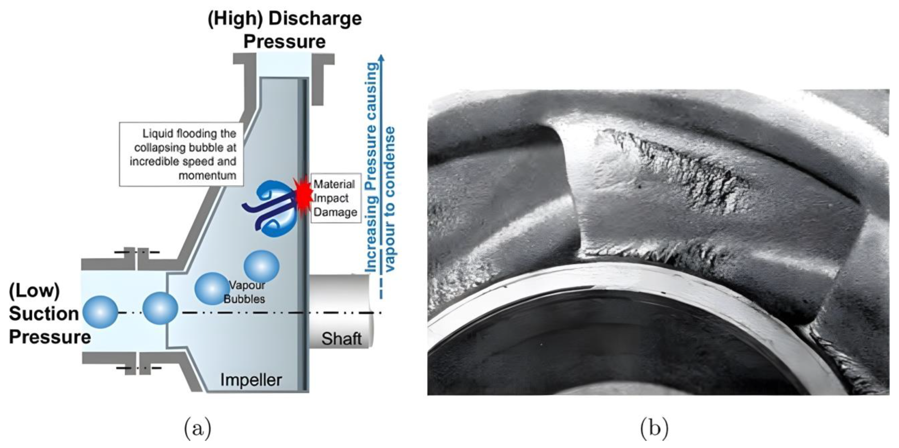
Figure 1. (a) Schematic diagram of centrifugal pump cavitation process. (b) Actual evidence of wearing on impeller blades due to cavitation [15].
Energies 17 05149 g001
Figure 2. Damaged centrifugal pump impellers due to cavitation [16,17].
Energies 17 05149 g002
Figure 3. Number of relative published works obtained from Web of Science.
Energies 17 05149 g003
Figure 4. The outline of this review.
Energies 17 05149 g004
Figure 5. Schematic representation of the humpback whale flipper leading-edge bulge [43].
Energies 17 05149 g005
Figure 6. Schematic diagram of centrifugal pump bionic vane [43].
Energies 17 05149 g006
Figure 7. Cavity volume in impeller channel at different NPSHa in the 5th rotation cycle [43]. (a) Variation of vacuole volume development in the impeller channel at NPSHa = 0.697; (b) Variation of vacuole volume development in the impeller channel at NPSHa = 0.085; (c) Variation of vacuole volume development in the impeller channel at NPSHa = 0.054; (d) Variation of vacuole volume development in the impeller channel at NPSHa = 0.044.
Energies 17 05149 g007
Figure 8. Bionic humpback whale flipper blade [44]. (a) Flipper of humpback whale; (b) the head shape of bionic centrifugal pump.
Energies 17 05149 g008
Figure 9. Bionic impeller [48]. (a) Leading-edge tubercle structure; (b) Actual object.
Energies 17 05149 g009
Figure 10. Definition of bionic leading-edge parameters [49].
Energies 17 05149 g010
Figure 11. Simulation of gas volume fraction of bionic leading-edge blade [49].
Energies 17 05149 g011
Figure 12. Blade contour lines [50].
Energies 17 05149 g012
Figure 13. Bionic leading-edge mechanism analysis [50]. (a) Overall distribution of pressure; (b) Local distribution of streamline of streamline; (c) Streamline diagram.
Energies 17 05149 g013
Figure 14. Bionic impeller modeling [51].
Energies 17 05149 g014
Figure 15. Spatial modes of the DMD under cavitation conditions [51]. (a) fs, (b) 2fs, (c) 3fs, and (d) 4fs, σ = 3.186.
Energies 17 05149 g015
Figure 16. Differences between two types of tongues: (a) OVT and (b) STVT [58].
Energies 17 05149 g016
Figure 17. Distribution of pressure coefficients and streamlines at cross-sections in four pumps [58].
Energies 17 05149 g017
Figure 18. Nautilus cross-sectional shape [59].
Energies 17 05149 g018
Figure 19. Gas–liquid two-phase distribution during liquid filling [59].
Energies 17 05149 g019
Figure 20. Sketch of bionic impeller with bionic convex domes [63].
Energies 17 05149 g020
Figure 21. Representative scanning electron micrographs of cuticles and fine hairs on the mesothorax of springtails (Collembola) and sea skaters (H. germanus), respectively [69]. (A,B) Springtails have primary granules (triangular) connected by ridges forming honeycomb patterns that prevent the intrusion of liquids on submersion. (C) Long needle-shaped hairs and tiny mushroom-shaped hairs on the dorsal and ventral mesothorax of sea skaters provide robust repellency against seawater. (D) Magnified micrograph of mushroom-shaped hairs.
Energies 17 05149 g021
Figure 22. Principle of cavitation damage suppression by GEMS [69]. (A) Liquid jet from a bubble collapsing close to a solid boundary affecting the substrate and causing erosion. The time scale corresponds to a cavitation bubble of Rmax ≈ 570 µm. (B) The gas entrapped inside the GEMS protrudes near the cavitation bubble and behaves as a free boundary. As a result, the liquid jet from the collapsing bubble is directed away from the substrate. The time scale shown is that of a cavitation bubble of Rmax ≈ 520 µm. The time in µs and maximum bubble radius depicted in (A,B) are typical values observed in the experiments. (C) The gas entrapped inside the GEMS expands because of the pressure field generated by the nearby cavitation bubble. Notice that the gas contained in the GEMS bulges outward and reaches an almost hemispherical shape during the expansion of the cavitation bubble as mentioned in the text. Image credit: Xavier Pita, Scientific Illustrator, KAUST.
Energies 17 05149 g022
Figure 23. Impellers for centrifugal pumps with non-smooth surfaces [73].
Energies 17 05149 g023
Figure 24. Surface morphology of superhydrophobic materials: (a) optical image; (b) three-dimensional morphology; (c) typical cross-sectional image of a superhydrophobic material [88].
Energies 17 05149 g024
Figure 25. Bone-coupled bionic metal coatings [90].
Energies 17 05149 g025
Figure 26. Experimental plot comparing cavitation of AS coatings with BHS-b coating [90]. (a,b) SEM images of the eroded cross-sections of the coatings. (c,d) SEM images of the eroded surfaces of the coatings. (e,f) the depth distribution on the eroded surface of the coatings according to the 2D contours given in Figure 26.
Energies 17 05149 g026
Table 1. Comparison of the main literature and optimization results based on humpback whale flipper bionic design.
AuthorInspired ByDesignEffectiveness
Zhao et al. [41]Humpback whale nodule effect.Biomimetic centrifugal pump blades.Reduced cavitation volume in impeller by 99.72%, stable hydraulic performance.
Wang et al. [42]Humpback whale flippers.Biomimetic centrifugal pump blades.Higher lift and slower cavitation development increased pump stability.
Li et al. [43]Humpback whale flippers.Biomimetic wavy trailing edge (STTE).Reduced pressure pulsation, improved hydraulic performance.
Zhang et al. [44]Humpback whale flippers.Biomimetic tubercles on leading edge.Reduced cavitation bubble volume by 9.67%, decreased drag coefficient by 9.36%.
Xu et al. [45]Humpback whale flippers.Biomimetic impeller.Increased head by up to 10%, minimal efficiency loss (<2.5%).
Wang et al. [47]Humpback whale nodule effect.Non-smooth sinusoidal leading edgeBetter anti-cavitation ability with shorter wavelengths.
Table 2. Time-averaged entropy of four pumps and the reduction compared to the prototype pump [58].
The Time-Averaged Total Entropy (J/m2)Reduction (%)Efficiency (%)
OVT3633083.4
STVT—133098.9384.7
STVT—233049.0785.1
STVT—3327010.0185.5
Table 3. Average shear stress of the blade [60].
Flow RateAverage Shear Stress (Pa)Shear Strain (%)
Smooth BladeBionic Blade
0.8 Qd22.0217.1322.16
1.0 Qd40.6330.0126.20
1.2 Qd85.1360.7529.00
1.4 Qd98.0071.1327.50
Disclaimer/Publisher’s Note: The statements, opinions and data contained in all publications are solely those of the individual author(s) and contributor(s) and not of MDPI and/or the editor(s). MDPI and/or the editor(s) disclaim responsibility for any injury to people or property resulting from any ideas, methods, instructions or products referred to in the content.