Article

A New Magnetic Coupler with High Misalignment Tolerance and Inherent Constant Current–Constant Voltage for Underground Wireless Charging

by
Kai Yan
,
Ruirong Dang
*,
Xudong Feng
and
Wenzhen Wang
*
Shaanxi Provincial Key Laboratory of Oil and Gas Well Measurement and Control Technology, Xi’an Shiyou University, Xi’an 710065, China
*
Authors to whom correspondence should be addressed.
Energies 2024, 17(20), 5130; https://doi.org/10.3390/en17205130
Submission received: 7 September 2024 / Revised: 12 October 2024 / Accepted: 14 October 2024 / Published: 15 October 2024
(This article belongs to the Section F1: Electrical Power System)

Abstract

:
In an underground inductive power transfer (IPT), it is inevitable to produce the phenomenon of misalignment between the transmitter and the receiver, which will reduce the output current, voltage and output efficiency of the whole IPT system. Aiming to solve this problem, a universal hybrid coupler is proposed, which can still stabilize the output in the expected range and has the ability of anti-misalignment when the X and Z directions are misaligned. The coupler is composed of a BP coupler and Γ type network. The secondary edge of the coupler introduces a Γ network, which decouples the two main coils on the same side of the receiver from the auxiliary coil and reduces the complexity of the system. The coupler can effectively reduce the coupling fluctuation caused by physical movement between the downhole transmitting end and the receiving end, thereby ensuring the stable output of the coupler. As a widely used IPT system, it can access the rest of the circuit topology whose output is independent of the load and achieve misalignment-tolerant output. Finally, based on the proposed hybrid IPT coupler theory, a 500 W misalignment-tolerant coupler prototype was built, and the compensation topologies were configured as series–series (SS) and series/inductance/capacitance/capacitor (S/LCC) structures. When the X and Z direction is misaligned, the constant current and voltage independent of the load can be output by switching the compensation topology. The experimental results are the same as the theoretical analysis.

1. Introduction

At present, inductive power transfer (IPT) technology has entered the lives of the general public, and people are paying more and more attention to it. Compared with traditional power transmission methods, IPT transmission is more flexible, safer, and can be widely used in various environments. Currently, it is commonly used in medical devices, consumer electronics, electric vehicles, rail trains, and other common fields [1,2,3,4,5]. Most of these have built-in battery modules as the receiving end of the IPT system, relying on the external power transmitter to power it in a constant current (CC) or constant voltage (CV) manner [6,7,8,9].
The IPT coupling system uses an alternating magnetic field as a medium and applies a loosely coupled transformer for energy transmission. In this process, most scholars assume that the primary coil and the secondary coil of the IPT system are completely aligned during research and can perform ideal high-efficiency transmission. However, when using the IPT transmission method, the primary and secondary coils will inevitably produce misalignment (horizontally and vertically), which greatly increases the reactive power of the coupling system and reduces the transmission efficiency of the entire system. Therefore, how to improve the coupling coefficient and transmit at a low coupling coefficient has become a cutting-edge goal in the study of IPT transmission [10,11,12,13].
In order to improve the misalignment capability of the IPT system, researchers have proposed a variety of optimization solutions, including changing the compensation topology, optimizing compensation parameters, changing the control method, and selecting a variety of magnetic coupling designs [14,15]. Among them, changing the compensation topology and optimizing the compensation parameters can reduce the reactive power in the coupler and improve the overall efficiency, and gradually become the first choice for optimization.
Improper charging methods will reduce battery life. Some scholars have proposed replacing traditional control methods with a CC/CV output compensation topology to extend battery life, and applying high-order network topologies for compensation, such as inductor–capacitor-series or series–capacitor–inductor–capacitor topologies and applying them to the CC/CV output. The high-order network topology is applied for compensation, such as inductor–capacitor-series (LC-series) and series–capacitor–inductor–capacitor (SC-LCC) topologies, for CC/CV output. A compensation topology is proposed that alternates between SS compensation and the S/LCC topology, using a single inverter to charge a bicycle [16]. However, these circuit compensation topologies all have the problem of misalignment between the transmitting end and the receiving end of the coupler, which inevitably causes magnetic leakage, making it impossible for the coupler to work in an ideal alignment state, so that the overall efficiency does not reach the expected effect. Some scholars have proposed to use double D (DD)–double D orthogonality between the transmitter and the receiver to increase the original single effective magnetic induction area to 4–5 times, which can reduce the efficiency reduction caused by partial misalignment [17]. Scholars proposed that by applying two two-dimensional subdomain analysis models in combination, and by using two transmitters and a square receiver to form a three-dimensional analytical model of a dual-polar plate IPT system, the system’s efficiency can be improved by reducing magnetic leakage using ferrite and aluminum shielding in the transmitters. However, the construction cost of this IPT system is relatively high and the reusability is low [18]. The bipolar (BP) coupler is similar to the DDQ coupler. Both are four-coil structures with anti-offset capability, reduce the reactive circulating current, and save some consumables costs [18,19,20,21,22,23,24]. The tripole plate (TP) three-coil structure, combined with an effective control scheme, optimizes the primary coil to improve the effective coupling factor in the traditional circuit topology, and can rely on multiple coils to decouple each other to obtain the optimal current [19]. Scholars proposed a wireless power transmission scheme for mobile loads. This scheme reduced the impact of misalignment through transmitter array signals and was tested on multiple mice with objective results [25]. However, in two or more overlapping coil couplers on the same side of the transmitter and the receiver, the BP coupler must meet the design requirements of the coupler mutual inductance, while reducing the cross mutual inductance with the remaining coils, resulting in the inability to independently design the various parameters between the overlapping coils of the transmitter and the receiver, which increases the difficulty of the work. When the abovementioned partial couplers are used to increase the compensation topology and optimize the parameters, numerical iteration is often required, which greatly increases the design cycle. Some scholars have proposed that adding two auxiliary coil resonant circuits to the traditional IPT system can improve the ability of the entire IPT system to resist misalignment. In this IPT system, the BP coupler is used, and when the primary and secondary sides are offset, the secondary side outputs a current within the expected range [20]. Some scholars have added a T-type network to the primary coil based on the BP coupler. By adjusting the compensation inductance in the T-type network, the mutual inductance fluctuation of the hybrid coupler can be kept within an acceptable range. However, the transmitter of the coupler requires more components to be aligned. The transmitter of the coupler requires a large number of components, and this study is applied to an oil well. Unlike the traditional car wireless charging model, the transmitter and the receiver are in an open-air environment. When the equipment is damaged, it can be handled at any time, and the structure of the receiver of the sports car is as simple as possible to reduce the failure rate. When applied to oil wells, the transmitter and the receiver work together in a deep well of several thousand meters. The receiver needs to be fixed. When one receiver is charged, the transmitter charges the remaining receivers one by one. Therefore, it is not recommended to have too many primary devices. During the process of placing the transmitter in the well, although the limiter ensures that the transmitter and the receiver are in a roughly predetermined position for power transmission, there is still a situation where the transmitter and the receiver are not completely aligned, resulting in magnetic leakage and, thus, cannot work in an ideal state.
In order to solve the shortcomings of the above-mentioned IPT system, this paper continues the work based on the research of Mai [21] and Wang [22] and proposes a new concept of a hybrid IPT coupler. The BP coupler is combined with the Γ -type circuit topology to form a new hybrid coupler with high misalignment tolerance. When the transmitter and receiver of the coupler have a large offset within a certain range, the mutual inductance MEQ (the equivalent mutual inductance) fluctuates less, which theoretically improves the coupler’s tolerance to misalignment. The coupler can be connected to a circuit compensation topology that is independent of the load, and the system can output the expected current/voltage. The proposed coupler can decouple the overlapping coils from each other by adjusting the parameter values in the Γ -type compensation network, reduce the cross-coupling mutual inductance, and reduce the amount of calculation. To this end, a 500 W wireless charging system based on the SS compensation topology IPT was built for verification.

2. Theoretical Derivation of Coil Anti-Misalignment

In this paper, the equivalent model of multi-coil coupling topology circuit is proposed as shown in Figure 1. Here, VAB and IP are two-port input voltage and input current, while VR and IS are output voltage and output current vectors. LPEQ and LSEQ are the equivalent self-inductance of the transmitter coil and the equivalent self-inductance of the receiver coil of the radio energy coupler, respectively; MEQ is the equivalent mutual inductance between the transmitter coil and the receiver coil.
According to the principle of electromagnetic induction, the two-port network matrix of the coupler can be obtained as follows:
V A B V R = j ω L P E Q M E Q M E Q L S E Q I P I S
The proposed coupler has a high misalignment tolerance, so this coupler can join many compensation topology networks. Due to unexpected circumstances, when the coil is misaligned, the MEQ can remain stable or fluctuate in an acceptable range, and the self-inductance of the primary transmitting coil and the secondary receiving coil do not change. Because the other compensation topology circuits are added to the coupler, the mutual inductance between the transmitter and the receiver has little influence on the whole coupling system when the transmitter coil and the receiver coil are misaligned, and the IPT system can still maintain stable output within the expected range.
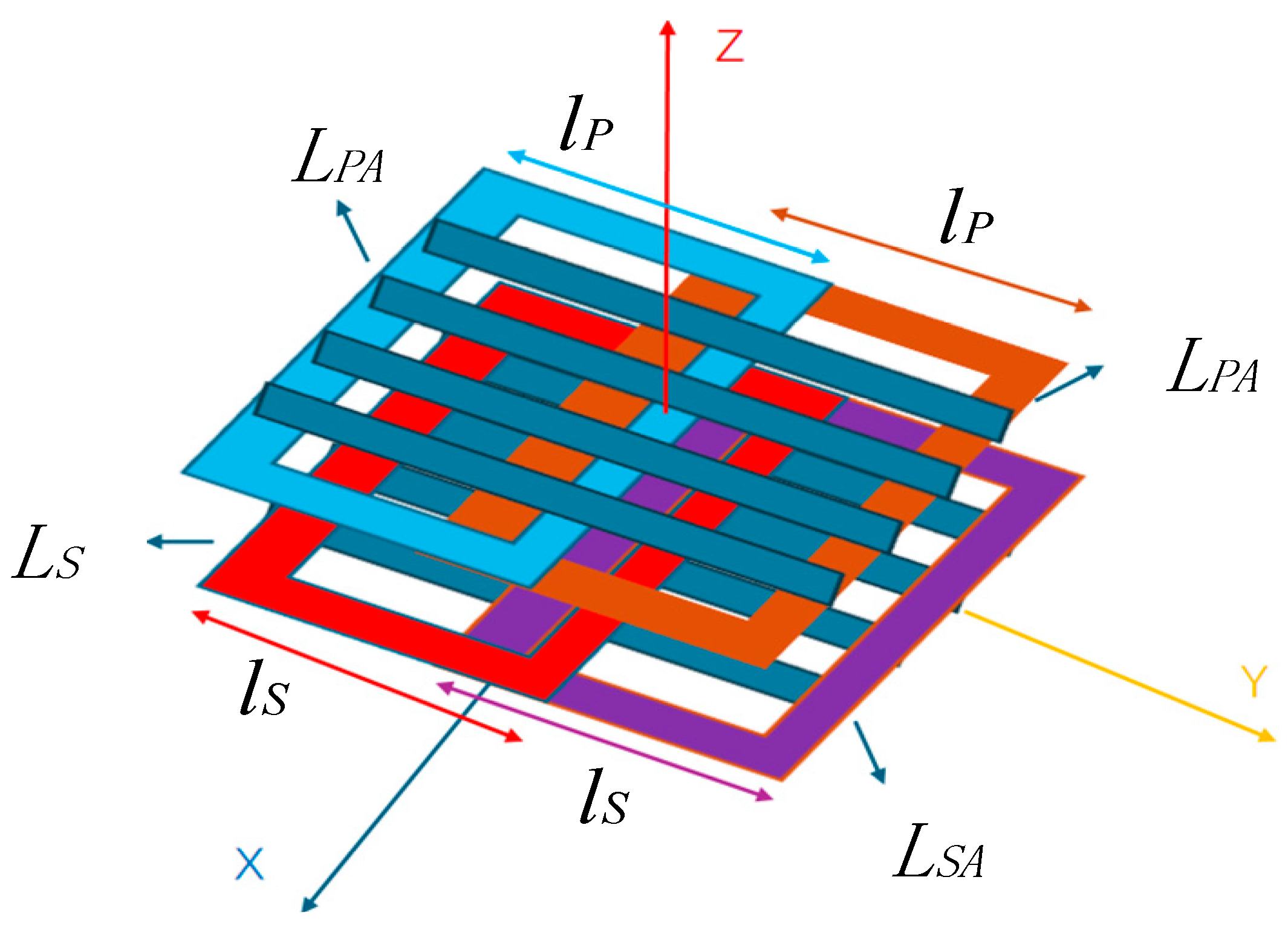
To achieve this intended purpose, the hybrid circuit topology coupler shown in Figure 2 is proposed in this paper. Based on the BP coupler, the coupler adds a Γ -type compensation topology to the original edge transmitter, which includes the CL compensation network in Figure 2a and the LC compensation network in Figure 2b. In Figure 2, LP, LS, LPA, LSA are the equivalent self-inductances of the four-coil BP coupler, respectively. LS1 and positive CS1 are passive components of the Γ -type compensation topology. MPS is the equivalent mutual inductance between the main coil LP at the transmitter and the main coil LS at the receiver. MPASA is the equivalent mutual inductance between the auxiliary coil LPA at the transmitter and the auxiliary coil LSA at the receiver. MPPA and MSSA have the same position profiles of the transmitter and receiver, respectively, and the equivalent mutual inductance between the main coil and the auxiliary coil. Due to the structural nature of the BP network, the equivalent mutual inductance MPPA and MSSA of the main coil and the auxiliary coil are much smaller than MPS and MPASA, so they can be ignored in the actual analysis process. After adding the Γ -type compensation topology, the overlapping area between the main coil and the auxiliary coil was constantly changed, and the overlapping coils of the same profile at the transmitter in the BP coupling structure were completely decoupling to reach MSSA = 0. This analysis is shown in Figure 2a, and describes how to achieve high misalignment tolerance and simplify its design by connecting CL compensation in a BP coupler.

2.1. Analysis of Coupler Misalignment Tolerance Error Based on CL Compensation Network

For the above structure (a), the circuit
V A B V R 0 0 = j ω L P M PS M PP A 0 M PS Z S 0 L S 1 M PP A 0 Z P A M P A S A 0 L S 1 M P A S A Z S A I P I S I P A I S A
In Formula (2)
Z S = j ω L S + j ω L S 1 + 1 j ω C S 1 Z P A = j ω L P A + 1 j ω C P A Z S A = j ω L S A + 1 j ω C S A + j ω L S 1
In the above formula, ω satisfies
ω = 1 L S 1 C S 1 = 1 ( L S A L S 1 ) C S A = 1 L P A C P A
Substituting Equation (4) into Equation (2), when the hybrid coupling structure is in a resonant state, IPA, ISA can be expressed as
I P A = L S 1 M P A S A I S I S A = M P P A M P A S A I P
Substituting (5) into (2), we can get that under the working state, the two-port expression of the hybrid coupling structure is
V A B V R = j ω L P M P S + L S 1 M P P A M P A S A M P S + L S 1 M P P A M P A S A L S I P I S
The terms in Equation (6) and Equation (1) correspond to each other. When the hybrid coupler is in working state, its corresponding equivalent mutual inductance is
M E Q = M P S + L S 1 M P P A M P A S A
In Equation (1), the equivalent coil self-inductance at the transmitter is LPEQ = LP and the equivalent self-inductance at the receiver is LSEQ = LS.
According to the design principle of Figure 2, the structure of the designed four-coil BP coupler is shown in Figure 3. According to the nature of the BP coupler, the main coil and the auxiliary coil in the same section need to be mechanically fixed and will not produce relative motion, so the mutual inductance MPPA and MSSA between the main coil and the auxiliary coil are almost constant [20]. In this structure, the positions of the main coil and the auxiliary coil are fixed, and the coil turns, and the size of the transmitter and the receiver are the same, so the equivalent mutual inductance MPS and MPASA values are approximately equal. Therefore, when coil misalignment occurs, the mutual inductance MPS and MPASA change in the same trend. Since there are positive and negative polarities between inductive coupling coils, “+” is defined as the mutual inductance between two positive polarity coupling coils, and “−” is the mutual inductance value between two negative polarity coupling coils.
Therefore, the equivalent mutual inductance in this coupling structure is
M E Q = M P S + L S 1 M P P A M P A S A
Since the basic parameters, such as coil size and the number of turns on the same side between the transmitter coil and the receiver coil are the same, the mutual inductance value and the mutual inductance parameter change are the same when the coil is offset and misaligned. After setting the coupler coil size and fixed air gap, its equivalent mutual inductance is MEQreq. When the coil is misaligned or offset, the mutual inductance will change, and α is defined as the acceptable mutual inductance fluctuation change rate. Where MEQalign is the equivalent mutual inductance of the coupler when the coils are aligned. The acceptable misalignment range of the coupler coil mutual inductance is [MPSmin,MPSmax].
Since MPS, MPASA, MPPA have corresponding polarities, and different polarity combinations exist, the combined polarities on the right side of Equation (8) are opposite. Therefore, the appropriate coil polarity must be selected to achieve a coupling system output. Under the condition of Equation (8), when coil MPS*MPPA*MPASA > 0, the compensation network should be connected to the Γ -type CL network. When coil MPS*MPPA*MPASA < 0, the compensation network is connected to the Γ -type LC network. The Γ -type network topology combination is shown in Table 1.
It can be seen from Equation (7) that when the BP coupling structure of Γ -type CL compensation network is connected, the internal CS1 and the coil parameters jointly determine the performance of the hybrid structure, and the L S 1 M P P A parameters will affect the value of the transmitter MPPA of the coupler. This value will affect the curve distribution in Figure 3 and the value range of [MPSmin,MPSmax]. On the premise that L S 1 M P P A remains stable, the equivalent mutual inductance |MEQ| of the hybrid coupling structure is a function of the coil mutual inductance |MPS|. A graph of the coil mutual inductance misalignment fluctuation function is shown in Figure 3. When the coil is misaligned, the equivalent mutual inductance changes, and the mutual inductance inflection point |MPSinflec| is
M P S inf lec = L S 1 M P P A
As can be seen from Figure 4, the hybrid coupler using the Γ -type CL compensation network has a higher tolerance for misalignment. When the mutual inductance coil is offset by M P S inf lec at the inflection point within the acceptable range, the equivalent mutual inductance |MEQ| between the corresponding coils has a minimum value, that is, M P S inf lec = ( 1 α ) M E Q align . Substituting this formula into (8) through (9) yields
L S 1 M P P A = ( 1 α 2 ) 2 M E Q a l i g n 2
When aligned state, substituting (10) into (8), it can be concluded
M E Q = M E Q r e q = M P S a l i g n + ( 1 α 2 ) 2 M E Q r e q 2 M P S a l i g n
Considering it as an equation function, we can calculate
M P S a l i g n = 1 ± 1 ( 1 α ) 2 2 M E Q a l i g n
Among them, |MPSalign| has two values, corresponding to points A and B in Figure 4, indicating the mutual inductance when they are aligned. From (12), we can obtain that the minimum value is |MPSmin| and the maximum value is |MPSmax| at the maximum misalignment, respectively.
M P S min = 1 2 α + α 2 M E Q a l i g n M P S max = 1 + 2 α + α 2 M E Q a l i g n
Therefore, the coupler has high anti-deviability when the coil is misaligned, and its equivalent mutual inductance range is [|MPSmin|,|MPSmax|].
Then, substituting Equation (10) into Equation (12), we can obtain
L S 1 = M P S a l i g n 2 M P P A ( 1 α 1 + α ( 2 α ) ) 2
It can be seen from Formula (14) that the value of CS1 is jointly determined by MPPA, MPS, and α.

2.2. Hybrid Coupler Design with Γ -Type BP Pad

The design steps for applying this coupler are as follows:
  • Fix the coupler alternating frequency and the air gap between the transmitter and the receiver.
  • Based on the above environmental conditions, configure the coils LP, LPA, LS, LSA and the number of turns of each coil NP, NPA, NS, NSA.
  • Measure MPS, MPASA, MSSA, MPPA, MPSA, MSPA between the above coils, and determine whether the mutual inductances |MSSA|,|MSPA| and |MSPA| are all 0?
  • If step 3 is not satisfied, adjust the parameters in step 2 and repeat steps 3 and 4.
  • Move the transmitter and the receiver to measure whether the fluctuation of the equivalent mutual inductance |MEQ| is less than 5%. And record the misalignment distance. If the condition is not satisfied, repeat steps 2–5.
  • Calculate LS1 by Formula (14) and calculate CPA, CSA, CS1 by Formula (4).

3. Design of Hybrid Coupler Using BP Pad Based on S/LCC Topology

3.1. Derivation of Coupler Output and Compensation

Through the above theoretical derivation of the BP hybrid coupler with type 12 compensation, the coupler has high misalignment or offset tolerance and can be connected to any topology network. Here, the S/LCC compensation topology is connected at the secondary edge, which is able to output constant current (CC)/constant voltage (CV) independent of the load. Thus, an IPT coupler with high resistance to misalignment or offset and constant current/voltage output is designed. The IPT hybrid coupler based on S/LCC topology compensation is shown in Figure 5. Where CP, CS and CS2 are compensating capacitors LP, LS and LS2 are compensating inductors. The system passes through the DC voltage source VIN, through the Q1–Q4 inverter circuit, D is the duty cycle of the control circuit, the angular frequency of the control system is ω, the output amplitude is vAB square wave, and θ is the phase Angle. The four switching tubes Q1, Q2, Q3, and Q4 are used with complementary phases, that is, the MOS tubes on the diagonal use the same set of driving signals. When the phase is switched, the MOS tubes on the same bridge arm are turned on at the same time. When Q1 and Q3 are turned on, Q2 and Q4 are turned off. The inverter circuit can output a bipolar square wave, and its Fourier decomposition is
v A B t = n 4 V in π sin π D 2 sin n ω t + θ , n = 1 , 3 , 5
If only the fundamental component of the sinusoidal form is considered, the DC source and AC power supply can be simplified as
v A B 1 t = 4 V in π sin π D 2 sin ω t + θ
At the secondary side receiver, four diodes are used to form a full-bridge rectifier and the access capacitor C0 is used to rectify and filter the induced current, and then supply power to the load R0. In Figure 5, V0 and I0 are the values of battery terminal voltage and current respectively. When the S2, S3 switches are in the on state and the S1 switch is in the off state, the secondary edge compensation topology is in the S compensation topology and the system maintains CC output. When the S1 switch is turned on and the S2 and S3 switches are in the off state, the secondary edge switches to the LCC compensation topology and the system maintains a CV output.

3.2. Analysis of Coupler CC Output

When the switch coupler is in CC mode, it can achieve CC output independent of load and zero-phase angle (ZPA), and the operating frequency of the coupler is
ω = 1 L S C S = 1 ( L S A L S 1 ) C S A = 1 L P C P
When the entire working system is in the resonant output state of working frequency ω , the load at the secondary output end is equivalent to RL.
i S = π 2 I O ν R = 4 π V O R L = ν R i S = 8 π 2 R 0
Figure 6 is an equivalent diagram of the secondary impedance in the series–series resonant mode. Z22 is the secondary side equivalent resistance, and its magnitude is ( ω M ) 2 Z 22 , when the coupler in Figure 5 is in constant current output state, Z 22 = 8 π 2 R 0 , its input impedance is
Z in = π 2 8 ω M E Q 2 R L
This paper shows the equivalent circuit in Figure 1, the two-port expression in (1) Current Gain
G CC = I 0 V A B = 1 j ω ( L P E Q + M E Q )
Since the system is in resonance when working, LPEQ is 0, the equivalent load of purely resistive impedance and the output current gain G of the coupler is
G CC = I 0 V A B = 1 ω M E Q
Here I0 and VAB are the vectors of current I0 and voltage VAB, respectively.
By putting Equation (16) into Equation (21), the coupler’s CC output can be obtained as
I 0 = 8 V in sin π D 2 π 2 ω M E Q = 8 V in sin π D 2 π 2 ω M P S + L S 1 M P P A M P S
The output current value of the coupler can be adjusted by adjusting the value of LS1 in the hybrid coupler, and the output current is not affected by the subsequent load of the coupler. In the above analysis, the equivalent mutual inductance MEQreq fluctuates in the range of (1 ± α)MEQreq when the transmitter and receiver of the coupler are misaligned laterally and vertically. Therefore, the output current I0 also fluctuates in the range of (1 ± α)I0 when the coupler outputs CC.

3.3. Analysis of Coupler CV Output

When the switching coupler is in CV mode, it can achieve CV output and a zero-phase angle (ZPA) independent of the load. The operating frequency of the coupler is
ω = 1 L f C f = 1 ( L S L S 2 ) C S = 1 L P C P
When the coupler is in CV output state, its input impedance is
Z IN = 8 π 2 M EQ L S 2 2 R L
In this working state, the equivalent load of purely resistive impedance and the output current gain G of the coupler is
G C V = V 0 V AB 1 = L S 2 M EQ
Here V0 and VAB are the vectors of v0 and vab, respectively.
By putting Equation (16) into Equation (25), it can be concluded that the coupler CV output voltage is
V 0 = 8 V in sin π D 2 L S 2 π 2 ( M P S + L S 1 M P P A M P S )
Therefore, when the coupler selects CV output, the output voltage V0 amplitude can be controlled by adjusting the Ls1 value, and the output point is not affected by the subsequent coupler load. In the above analysis, the equivalent mutual inductance MEQreq fluctuates in the range of (1 ± α) MEQreq when the transmitter and receiver of the coupler are misaligned laterally and vertically. Therefore, when the coupler outputs CV, the output voltage V0 also fluctuates in the range of (1 ± α)V0.

3.4. Magnetic Field Simulation of Downhole Coupling Device

The loosely coupled transformer is a key part of the entire underground IPT system, capable of completing the design of the IPT system transmission task. Its structural characteristics will have an impact on the entire IPT system. Due to the symmetrical nature of the coupling device, when the underground receiving end is fixed, the transmitter and receiver may not be perfectly aligned, but it will not affect the overall energy transmission. At the same time, the structure has relatively small magnetic leakage, and in the underground wellbore it has certain magnetic shielding function. Figure 7 shows the actual model of the underground loose coupling transformer in this design. The orange part is the coil, and the brown part is the ferrite. When the distance between the transmitter and the receiver of the IPT system is very close, the coupling coefficient becomes very high based on the structural characteristics, and the magnetic leakage is small. The detailed data of the coupling mechanism are shown in Table 2.
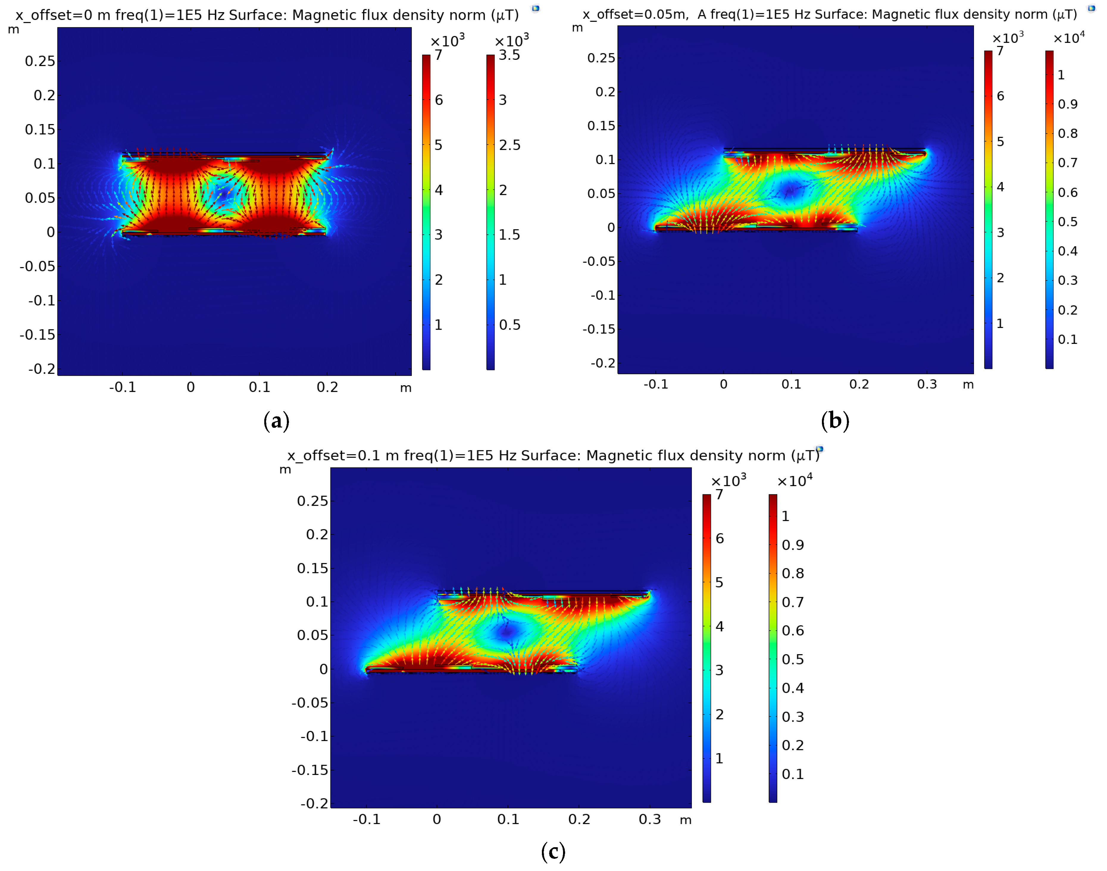
In order to analyze the transmission characteristics of the IPT system, COMSOL 6.1 software is used to build a 3D model of the structure 1:1, and the stable magnetic field simulation is carried out for the deviation of 0 mm, 50 mm, 100 mm in the X direction and −10 mm, 0 mm, 50 mm in the Z direction, and the magnetic flux distribution of the coupler in XZ can be obtained, as shown in Figure 8 and Figure 9.
Figure 8a and Figure 9b show the magnetic flux distribution diagram in the XZ plane when the transmitter and receiver of the coupler are directly aligned. The lines with arrows in this figure are the main loops of the effective flux between the transmitter and the receiver hinges. In the ideal state, the two magnetic flux loops of the coupler are independent of each other and do not interfere with each other. At the same time, ferrite panels are arranged at the transmitting and receiving ends of the coupler, which makes the reluctance of most magnetic circuits become small and facilitates the passage of magnetic field lines. Therefore, the magnetic leakage of the coupling device is small, but the coupling coefficient is very large, which is consistent with the previous analysis.
In Figure 8b,c, the XZ cross-section flux distribution of the coupling device occurs when the lateral misalignment in the X direction is 50 mm and 100 mm, respectively. It can be clearly seen from figures (b) and (c) that the number and intensity of magnetic inductive lines are significantly reduced compared with those in the positive alignment of (a), which can indicate that no matter how much distance deviation occurs in the X direction, certain magnetic leakage will be caused, thus reducing the coupling coefficient.
Figure 9a,c shows the magnetic flux distribution of the coupling device XZ section when the longitudinal offset in the Z direction is −10 mm and 50 mm, respectively. It can be seen from the figure that compared with the positive position in (b), when the Z direction is reversely offset by −10 mm, the number and intensity of magnetic flux lines are slightly increased. When the offset between the transmitter and the receiver reaches 50 mm, the number and intensity of magnetic flux lines are slightly weakened. It can be explained that the transmitter and the receiver are as close as possible in the Z direction. No matter how large the offset is, it will cause a certain amount of magnetic leakage. However, due to the downhole mechanical structure, material process limitations and considerations for wellbore protection, figure (b) is selected as the working node.

4. Experimental Verification

4.1. Build the Experimental Prototype

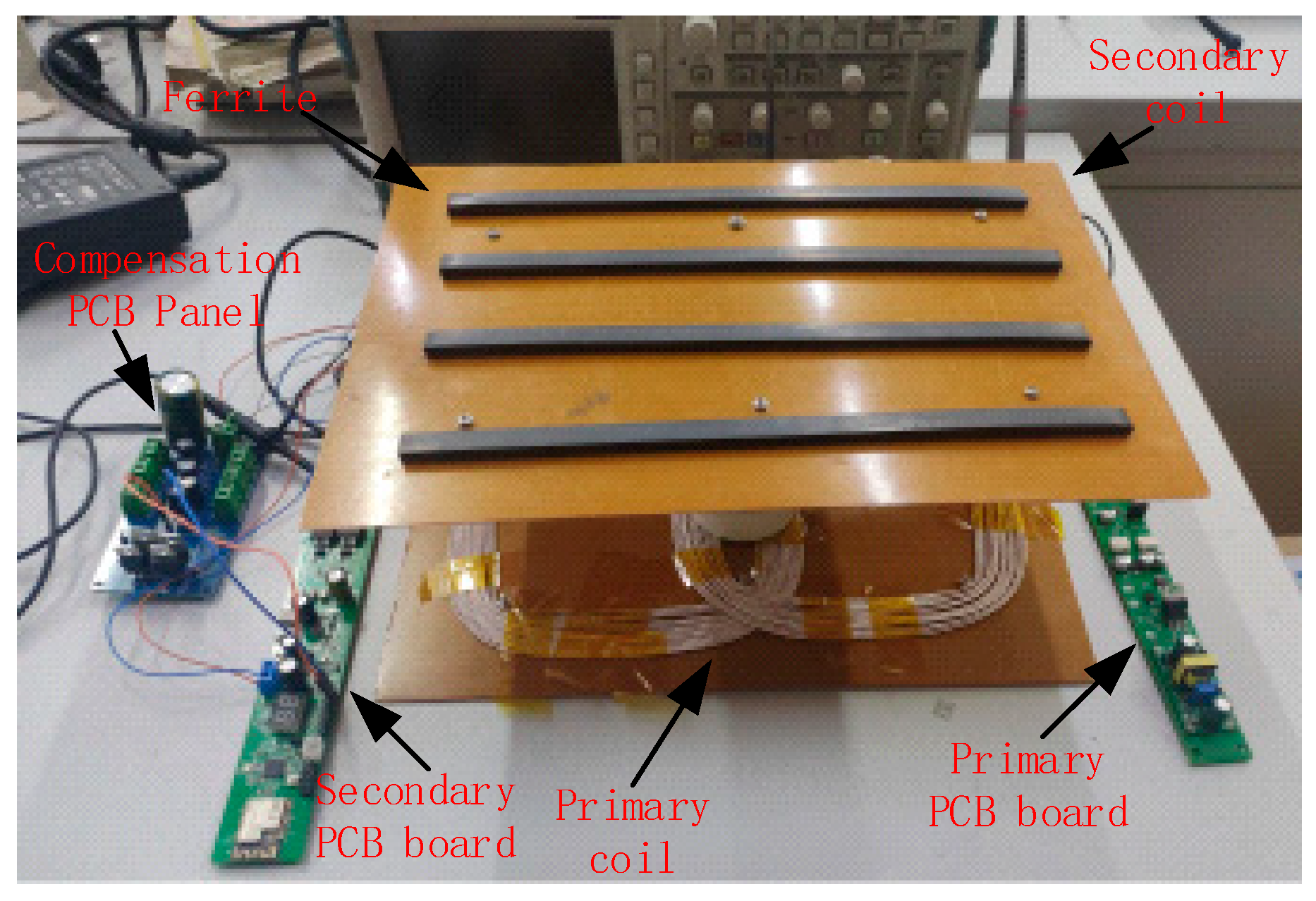
In order to verify the above theoretical accuracy, the prototype platform shown in Figure 10 is built according to the circuit in Figure 5.
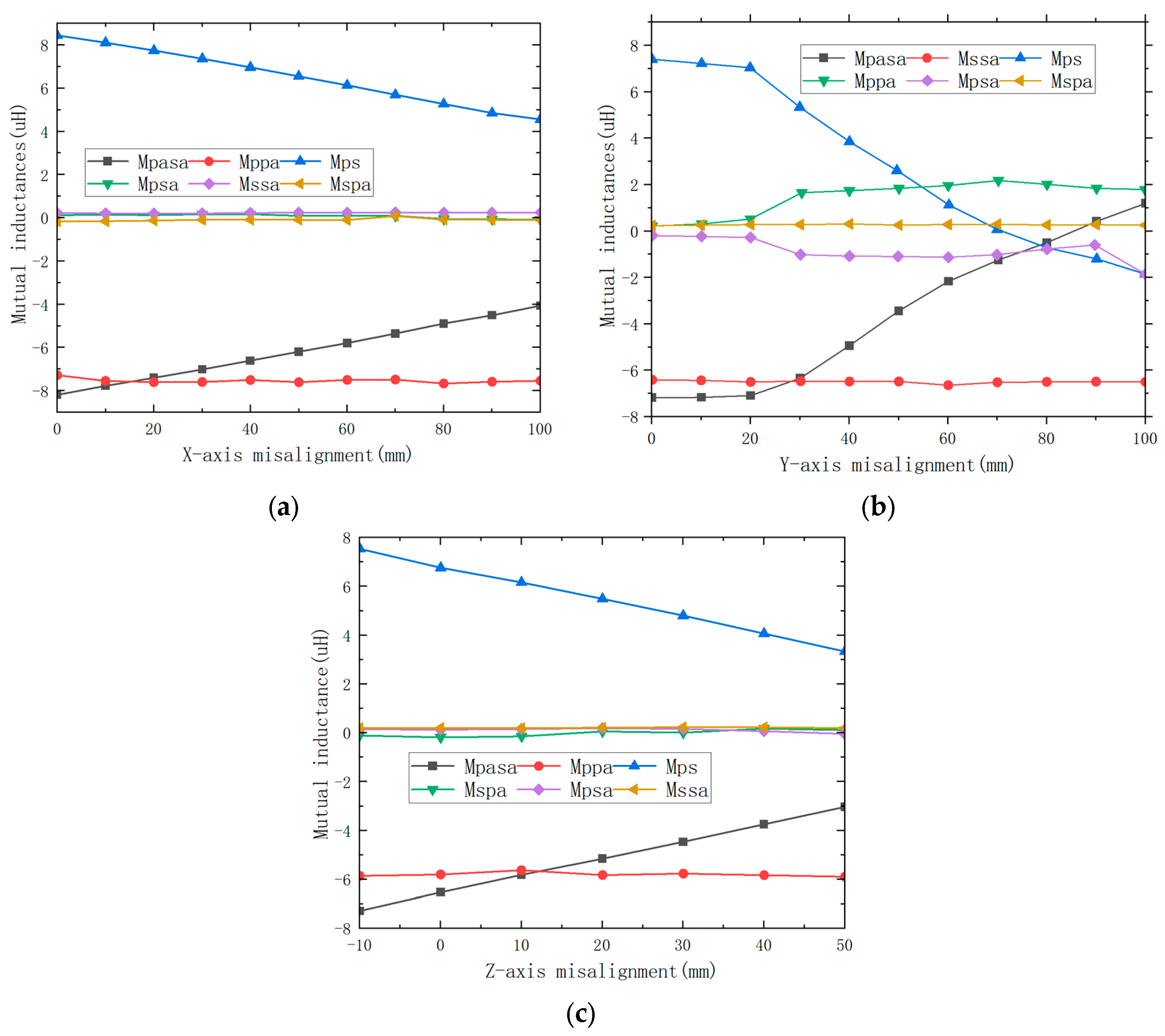
The configuration parameters of the coupler experimental setup are shown in Table 2. The control chip used is TMS320F28334Z (Texas Instruments, Dallas, TX, USA), the frequency is 100 k. The distance between the transmitter and the receiver is 100 mm, and the coupler plane size is 200 mm × 200 mm. The distance between the transmitter and the receiver is 110 mm. In order to ensure that the mutual inductance MPSA and MSPA between the main coil and the auxiliary coil at the transmitter and receiver are sufficiently small, the number of coil turns at the transmitter is 13 and the number of coil turns at the receiver is 12. The acceptable fluctuation variation range of the equivalent mutual inductance MEQ between the coils is 5%. The mutual inductance between the coils is shown in Figure 11.

4.2. Misalignment Tolerance and CC Output

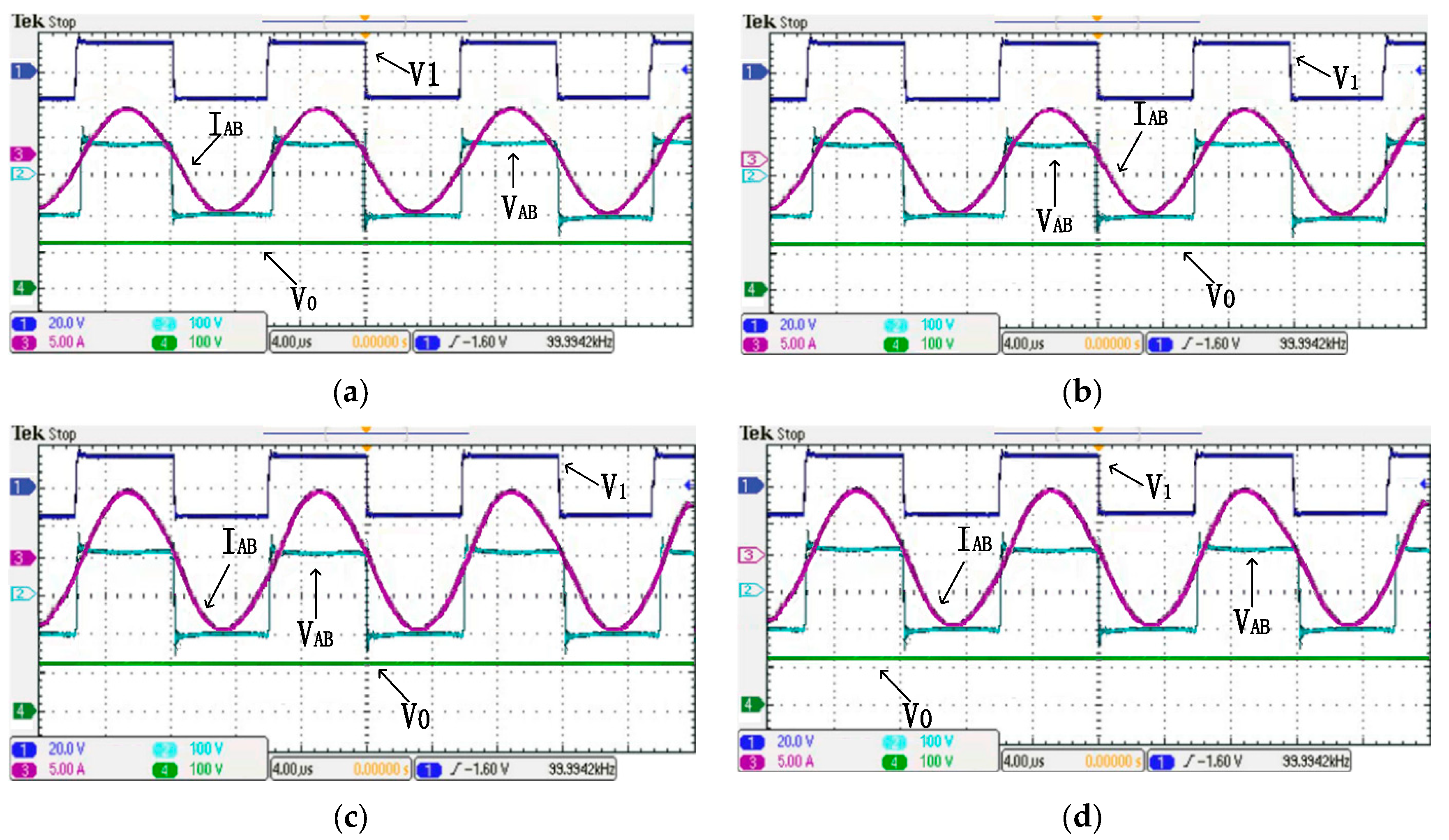
Figure 12a,b shows the experimental waveforms when the transmitter is aligned with the receiver and misaligned by 100 mm in the X-axis direction when the load R0 = 20 Ω, respectively. Where V1 is the driving voltage of the MOS transistor control stage, VAB is the inverter output voltage, IAB is the output current, and I0 is the secondary side output current. It can be seen from Figure 12a,b that the output current I0 can keep 4 A unchanged when the transmitter and the receiver appear a 100 mm dislocation misalignment in the X direction. In Figure 12c,d, when the load R0 = 30 Ω, the output current I0 can still maintain 4 A unchanged when the misalignment or offset of the transmitter and receiver in the Z direction is 50 mm. The coupled system can output a CC independent of the load when the offset in the X direction is 100 mm and the offset in the Z direction is 50 mm. Combined with Figure 11a,c, it can be seen that the equivalent mutual inductance MEQ value between the transmitter and the receiver varies in the range of 5%, but the output current waveform fluctuates slightly, and the overall current output characteristics are not affected, which indicates that the coupler system meets the expected requirements.

4.3. Misalignment Tolerance and CV Output

Figure 13a,b demonstrates the experimental waveforms when the transmitter is aligned with the receiver and misaligned by 100 mm in the X-axis direction when the load R0 = 40 Ω, respectively. Where V1 is the driving voltage of the MOS transistor control stage, VAB is the inverter output voltage, IAB is the output current, and V0 is the secondary side output current. It can be seen from Figure 13a,b that the output current V0 can remain unchanged at 100 V when the transmitter and the receiver appear to have a 100 mm misalignment in the X direction. In Figure 13c,d, when the load RL = 50 Ω, the output current V0 can still maintain 100 V when the transmitter and the receiver have a 50 mm misalignment in the Z direction. The coupled system can output a CV independent of the load when the misalignment in the X direction is 100 mm and the misalignment in the Z direction is 50 mm. Combined with Figure 11a,c, it can be seen that the equivalent mutual inductance MEQ value between the transmitter and the receiver varies in the range of 5%, but the output voltage waveform fluctuates slightly, and the overall voltage output characteristics are not affected, which indicates that the coupler system meets the expected requirements.

4.4. Misalignment Tolerance and Output Efficiency

Figure 14 shows the efficiency change curve of the CC output and CV output of the IPT system when the transmitter and receiver are completely positive. When the system works in CC mode, the system efficiency increases with the increase of load resistance (output efficiency increases). When the system works in the CV output mode, the system efficiency decreases as the load resistance increases (the output efficiency decreases). When the output load R0 = 35 Ω, the maximum efficiency is 90.6%.
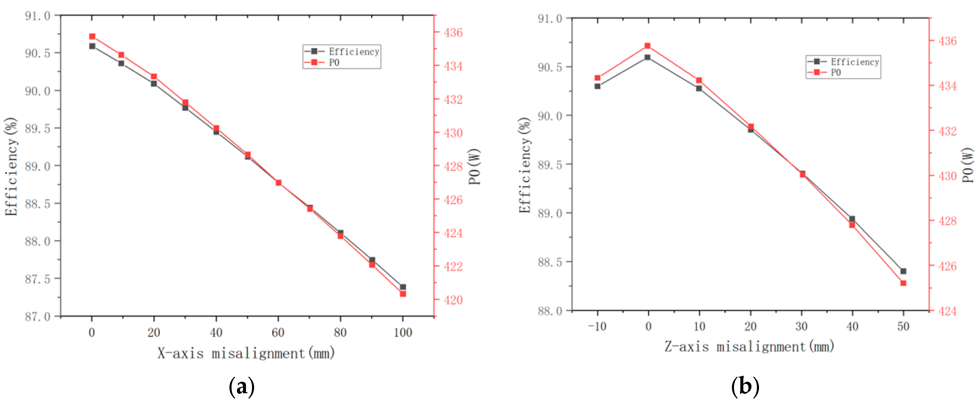
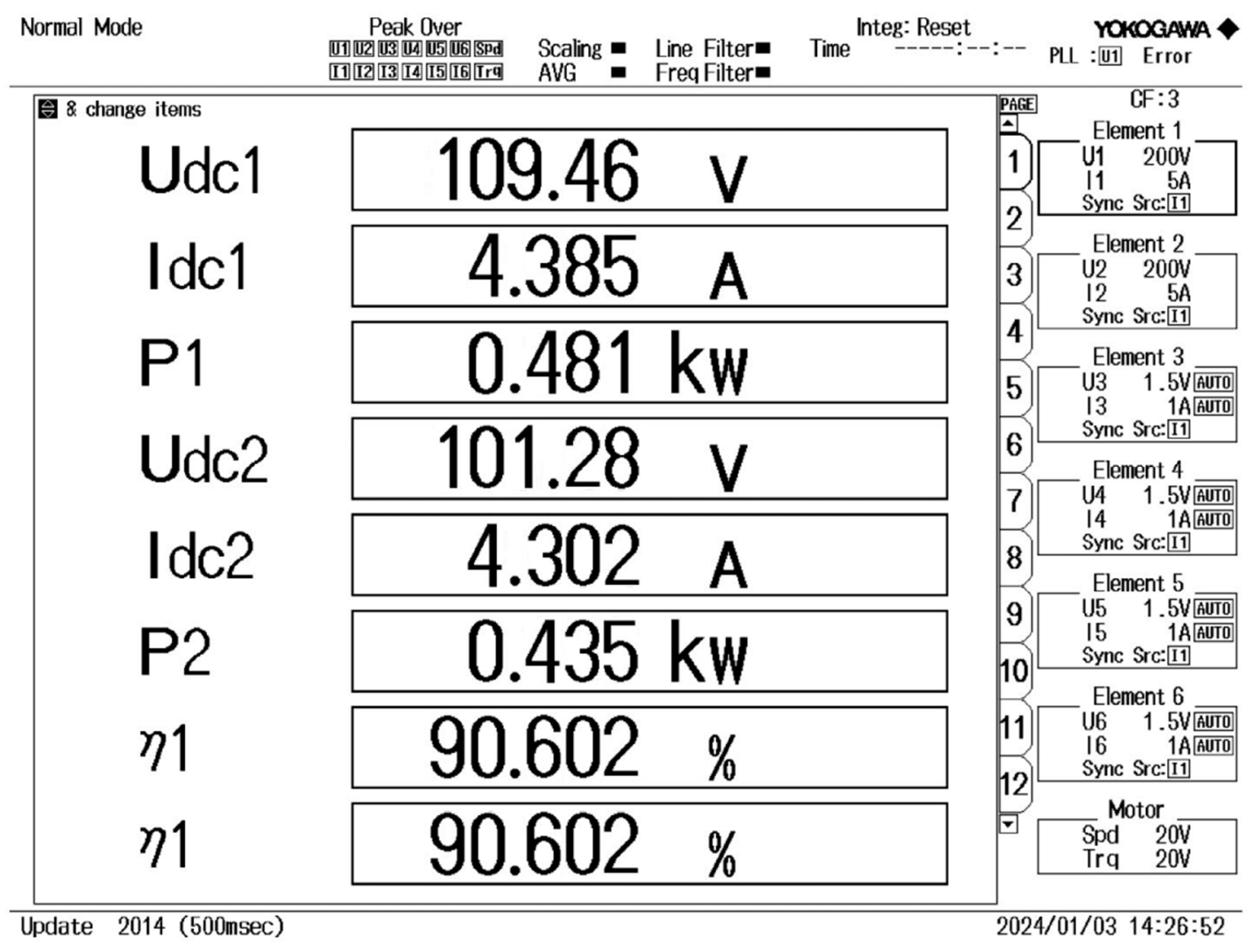
Figure 15 shows the output power and output efficiency curves when RL = 20 ohms and the transmitter and receiver are offset in the X and Z directions. The equivalent mutual inductance and output power of the coupler should be approximately the same when there is no misalignment in the coupler. When the coupler is in the X, Z direction, the equivalent mutual inductance MEQ starts to decrease significantly. In Figure 15a, when the offset occurs in the X direction, the output efficiency fluctuates slightly with the increase of the offset distance, but the overall efficiency decreases with the increase of the offset distance, and the output power also decreases. In Figure 15b, when the Z-direction is offset, efficiency is significantly increased to 90.6% from −10 mm to 0 mm. However, in the range from 0 mm to 50 mm, the power and efficiency show a downward trend at the same time. In summary, it can be concluded that the efficiency of this IPT system decreases when the forward misalignment of the X and Z axes occur. Figure 16 is a diagram showing the power efficiency output when the system is fully loaded, and the transmitter and receiver are completely aligned.
Therefore, when the misalignment distance in the X and Y direction is [−100 mm, 100 mm], and the misalignment distance in the Z direction is [−10 mm, 50 mm], the mutual inductance between the transmitter and the receiver fluctuates in the range of 5%. The output current fluctuation range still meets Equation (22) and should be kept in the range of [3.8 A, 4.2 A]. Its output voltage fluctuation range still meets Equation (26) and should be kept in the range of [105 V, 115 V]. When the coupler is misaligned in the X and Z direction, the measured output efficiency data plot is shown in Figure 13, and the measured results are the same as the theoretical results. It can be concluded that the hybrid coupler has a high tolerance when the transmitter and receiver coils are misaligned.
In order to directly reflect the advantages of the coupler designed in this paper, some similar couplers were investigated, and a comparison worksheet was made. The main parameters include the coupler composition, the number of coils, the coupler output mode, among other parameters. The comparison results are shown in Table 3. It can be seen from Table 3 that the coupler designed in this paper performs well, mainly in the following aspects: 1. Within the offset range, the output fluctuation range can be controlled within 5%, meeting the expected effect; 2. The number of compensation components is relatively small at 3. It can achieve constant current and constant voltage output that is independent of the load.

5. Conclusions

In order to improve the reliability of underground wireless charging, a hybrid coupler with high misalignment tolerance was proposed. The hybrid coupler combines a Γ -type network with a four-coil BP coupler to reduce the coupling fluctuation caused by the physical offset between the transmitter and the receiver within a certain range. It can greatly improve the tolerance of the coupler’s transmitter and receiver to resist misalignment or offset. It can be connected to any compensation topology and output a CC/CV that is independent of the load. The hybrid coupler has high resistance to misalignment in the range of 100 mm in the X direction and 50 mm in the Z direction, and its CC and CV output fluctuations are maintained in the range of 5%. Using the coupler to access SS and S/LCC compensation topology, a 500 W prototype was built. The results show that the coupler has an anti-misalignment ability in the X and Z direction, and the misalignment transmission efficiency can reach 90.6%.

Author Contributions

Conceptualization, K.Y.; methodology, K.Y.; software, K.Y.; validation, K.Y. and R.D.; formal analysis, R.D. and X.F.; investigation, R.D.; resources, R.D.; data curation, K.Y.; writing—original draft preparation, K.Y.; writing—review and editing, K.Y. and W.W.; visualization, R.D.; supervision, R.D. and W.W.; project administration, R.D.; funding acquisition, R.D. All authors have read and agreed to the published version of the manuscript.

Funding

This research was funded by National Natural Science Foundation of China, grant number 41874158.

Data Availability Statement

The data presented in this study are available on request from the corresponding author.

Acknowledgments

Thank you for the experimental environment provided by the Key Laboratory of Oil and Gas Well Measurement and Control in the Shaanxi Province of Xi’an Shiyou University.

Conflicts of Interest

The authors declare that they have no known competing financial interests or personal relationships that could have appeared to influence the work reported in this paper.

References

  1. Nithiyanandam, V.; Sampath, V. Approach-Based Analysis on Wireless Power Transmission for Bio-Implantable Devices. Appl. Sci. 2022, 13, 415. [Google Scholar] [CrossRef]
  2. Nutwong, S.; Sangswang, A.; Naetiladdanon, S. An inverter topology for wireless power transfer system with multiple transmitter coils. Appl. Sci. 2019, 9, 1551. [Google Scholar] [CrossRef]
  3. Yang, X.; Yang, J.; Fan, J.; Wang, B.; Li, D. A Magnetic Field Containment Method for an IPT System with Multiple Transmitting Coils Based on Reflective Properties. Electronics 2023, 12, 653. [Google Scholar] [CrossRef]
  4. Mai, R.; Chen, Y.; Zhang, Y.; Yang, N.; Cao, G.; He, Z. Optimization of the passive components for an S-LCC topology-based WPT system for charging massive electric bicycles. IEEE Trans. Ind. Electron. 2017, 65, 5497–5508. [Google Scholar] [CrossRef]
  5. Feng, H.; Tavakoli, R.; Onar, O.C.; Pantic, Z. Advances in high-power wireless charging systems: Overview and design considerations. IEEE Trans. Transp. Electrif. 2020, 6, 886–919. [Google Scholar] [CrossRef]
  6. Jo, S.; Shin, C.S.; Kim, D.H. Novel design method in wireless charger for SS topology with current/voltage self-limitation function. Appl. Sci. 2023, 13, 1488. [Google Scholar] [CrossRef]
  7. Li, J.; Zhang, X.; Tong, X. Research and Design of Misalignment-Tolerant LCC–LCC Compensated IPT System with Constant-Current and Constant-Voltage Output. IEEE Trans. Power Electron. 2022, 38, 1301–1313. [Google Scholar] [CrossRef]
  8. Li, G.; Jo, C.H.; Shin, C.S.; Jo, S.; Kim, D.H. A Load-Independent Current/Voltage IPT Charger with Secondary Side-Controlled Hybrid-Compensated Topology for Electric Vehicles. Appl. Sci. 2022, 12, 10899. [Google Scholar] [CrossRef]
  9. Campi, T.; Cruciani, S.; Maradei, F.; Feliziani, M. Efficient wireless drone charging pad for any landing position and orientation. Energies 2021, 14, 8188. [Google Scholar] [CrossRef]
  10. ElGhanam, E.; Hassan, M.; Osman, A.; Kabalan, H. Design and performance analysis of misalignment tolerant charging coils for wireless electric vehicle charging systems. World Electr. Veh. J. 2021, 12, 89. [Google Scholar] [CrossRef]
  11. Varikkottil, S.; Febin Daya, J.L. Estimation of optimal operating frequency for wireless EV charging system under misalignment. Electronics 2019, 8, 342. [Google Scholar] [CrossRef]
  12. Ghazizadeh, S.; Ahmed, K.; Seyedmahmoudian, M.; Mekhilef, S.; Chandran, J.; Stojcevski, A. Critical Analysis of Simulation of Misalignment in Wireless Charging of Electric Vehicles Batteries. Batteries 2023, 9, 106. [Google Scholar] [CrossRef]
  13. Niu, S.; Zhao, Q.; Chen, H.; Yu, H.; Niu, S.; Jian, L. Underwater wireless charging system of unmanned surface vehicles with high power, large misalignment tolerance and light weight: Analysis, design and optimization. Energies 2022, 15, 9529. [Google Scholar] [CrossRef]
  14. Wang, Y.; Yao, Y.; Liu, X.; Xu, D.; Cai, L. An LC/S compensation topology and coil design technique for wireless power transfer. IEEE Trans. Power Electron. 2017, 33, 2007–2025. [Google Scholar] [CrossRef]
  15. Wang, Y.; Yao, Y.; Liu, X.; Xu, D. S/CLC compensation topology analysis and circular coil design for wireless power transfer. IEEE Trans. Transp. Electrif. 2017, 3, 496–507. [Google Scholar] [CrossRef]
  16. Mai, R.; Chen, Y.; Li, Y.; Zhang, Y.; Cao, G.; He, Z. Inductive power transfer for massive electric bicycles charging based on hybrid topology switching with a single inverter. IEEE Trans. Power Electron. 2017, 32, 5897–5906. [Google Scholar] [CrossRef]
  17. Budhia, M.; Boys, J.T.; Covic, G.A.; Huang, C.Y. Development of a single-sided flux magnetic coupler for electric vehicle IPT charging systems. IEEE Trans. Ind. Electron. 2011, 60, 318–328. [Google Scholar] [CrossRef]
  18. Luo, Z.; Nie, S.; Pathmanathan, M.; Han, W.; Lehn, P.W. 3-D analytical model of bipolar coils with multiple finite magnetic shields for wireless electric vehicle charging systems. IEEE Trans. Ind. Electron. 2021, 69, 8231–8242. [Google Scholar] [CrossRef]
  19. Kim, S.; Covic, G.A.; Boys, J.T. Tripolar pad for inductive power transfer systems for EV charging. IEEE Trans. Power Electron. 2016, 32, 5045–5057. [Google Scholar] [CrossRef]
  20. Chen, Y.; Yang, B.; Zhou, X.; Li, Q.; He, Z.; Mai, R.; Lai, J.S. A hybrid inductive power transfer system with misalignment tolerance using quadruple-D quadrature pads. IEEE Trans. Power Electron. 2019, 35, 6039–6049. [Google Scholar] [CrossRef]
  21. Mai, R.; Yang, B.; Chen, Y.; Yang, N.; He, Z.; Gao, S. A misalignment tolerant IPT system with intermediate coils for constant-current output. IEEE Trans. Power Electron. 2019, 34, 7151–7155. [Google Scholar] [CrossRef]
  22. Wang, Y.; Liu, H.; Yu, H.; Wu, F.; Wheeler, P.; Zhou, Q.; Zhao, S. A misalignment-tolerant hybrid coupler for electric vehicle IPT charging systems. IEEE Trans. Vehhnol. 2023, 72, 12845–12856. [Google Scholar] [CrossRef]
  23. Chen, Y.; Yang, B.; Kou, Z.; He, Z.; Cao, G.; Mai, R. Hybrid and reconfigurable IPT systems with high-misalignment tolerance for constant-current and constant-voltage battery charging. IEEE Trans. Power Electron. 2018, 33, 8259–8269. [Google Scholar] [CrossRef]
  24. Zhao, L.; Thrimawithana, D.J.; Madawala, U.K. Hybrid bidirectional wireless EV charging system tolerant to pad misalignment. IEEE Trans. Ind. Electron. 2017, 64, 7079–7086. [Google Scholar] [CrossRef]
  25. Pahlavan, S.; Ashtiani, S.J. Rotation-Tolerant Wireless Power Transmission Scheme with Smart Positioning for Cognitive Research on Moving Animals. IEEE Trans. Biomed. Circuits Syst. 2023, 18, 123–130. [Google Scholar] [CrossRef]
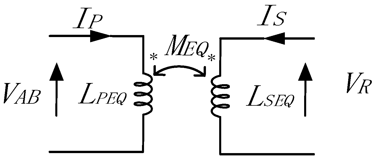
Figure 1. IPT coupler equivalent model diagram.
Energies 17 05130 g001
Figure 2. A hybrid coupler with Γ -type compensation network is proposed. (a) Adding a CL compensation network, (b) Adding an LC compensation network Two-port.
Energies 17 05130 g002
Figure 3. The conventional BP coupler.
Energies 17 05130 g003
Figure 4. Waveforms of MEQ and MPS changes.
Energies 17 05130 g004
Figure 5. S/LCC compensated IPT hybrid coupler.
Energies 17 05130 g005
Figure 6. Secondary side equivalent diagram.
Energies 17 05130 g006
Figure 7. Structure diagram of downhole loose coupling transformer.
Energies 17 05130 g007
Figure 8. Coupler misalignment in X direction, XZ cross section magnetic flux distribution diagram, (a) X = −10 mm, (b) X = 50 mm, (c) X = 100 mm.
Energies 17 05130 g008
Figure 9. Coupler misalignment in Z direction, XZ cross section magnetic flux distribution diagram, (a) X = −10 mm, (b) X = 0 mm, (c) X = 50 mm.
Energies 17 05130 g009aEnergies 17 05130 g009b
Figure 10. Experimental platform of hybrid coupler.
Energies 17 05130 g010
Figure 11. Misalignment mutual inductance variation curve between transmitter and receiver: (a) X-axis misalignment, (b) Y-axis misalignment, (c) z-axis misalignment.
Energies 17 05130 g011
Figure 12. Experimental waveform in CC output mode: (a) R0 = 20 Ω, the primary and secondary edges are in the positive alignment state, X = 0 mm; (b) R0 = 20 Ω, the primary and secondary edges are misalignment along the X direction X = 100 mm; (c) R0 = 30 Ω, the primary and secondary edges are in the positive alignment state, Z = 0 mm; (d) R0 = 30 Ω, the primary and secondary edges are misalignment along the Z direction, Z = 50 mm.
Energies 17 05130 g012
Figure 13. Experimental waveform in CV output mode: (a) R0 = 40 Ω, the primary and secondary edges are in the positive alignment state, X = 0 mm; (b) R0 = 40 Ω, the primary and secondary edges are offset along the X direction X = 100 mm; (c) R0 = 50 Ω, the primary and secondary edges are in the positive alignment state, Z= 0 mm; (d) R0 = 50 Ω, the primary and secondary edges are misalignment along the Z direction, Z = 50 mm.
Energies 17 05130 g013
Figure 14. Efficiency varies with load in CC/CV output mode.
Energies 17 05130 g014
Figure 15. The relationship between coupler misalignment and output efficiency: (a) X-direction misalignment, (b) Z-direction misalignment.
Energies 17 05130 g015
Figure 16. Output power of coupling system facing the position.
Energies 17 05130 g016
Table 1. The polarity of the two hybrid coupler coils proposed.
NumberMPSMPASAMPPA Γ -Type Network
1+++LC network
2+
3+
4+
5+CL network
6++
7
8++
Table 2. IPT prototype circuit parameters.
ParameterValueParameterValue
LP31.3 μHCP28.9 nF
LS28.3 μHCS216.1 nF
LPA31.8 μHCPA28.6 nF
LSA29.1 μHCSA30.4 nF
LS13.72 μHCS126.8 nF
Table 3. Effect of different coupler offsets on output fluctuations.
ParameterRef. [25]Ref. [24]Ref. [21]Ref. [22]This Work
Coil structureBPDDQQDQPBPBP
Maximum Size (cm)39 × 7340 × 4040 × 4040 × 4030 × 30
Misalignment Tolerance rangex-misalignment:
+160 (20%)
y-misalignment: N/A
Z-misalignment:
±50 mm (16.6%)
X-Misalignment:
±200 mm (50%)
Y-Misalignment:
50 mm (12%)
Z-Misalignment:
±50 mm (33.33%)
X-Misalignment:
+15 (37.5%)
Y-Misalignment:
±15 (37.5%)
X-Misalignment:
±3.5 (23.3%)
X-Misalignment:
±225 mm (50%)
Y-Misalignment:
±60 mm (20%)
Z-Misalignment:
±50 mm (33.33%)
X-Misalignment:
±100 mm (33.3%)
Y-Misalignment:
±60 mm (20%)
Z-Misalignment:
±50 mm (33.33%)
Output fluctuation10%5%5%5%5%
Output characteristicCCCC and CVCVCC CC and CV
Increase the degree of freedom for couplerNONONONOYes
Disclaimer/Publisher’s Note: The statements, opinions and data contained in all publications are solely those of the individual author(s) and contributor(s) and not of MDPI and/or the editor(s). MDPI and/or the editor(s) disclaim responsibility for any injury to people or property resulting from any ideas, methods, instructions or products referred to in the content.