1. Introduction
Recently, increasing energy consumption and environmental pollution have become a major concern for economic development worldwide, especially in developing countries [
1,
2,
3,
4]. In response to these challenges, heat pump technology has gained popularity and is widely used in various fields [
5,
6,
7].
Decarbonisation scenarios calculated by the Intergovernmental Panel on Climate Change (IPCC) clearly show that if global warming is to be limited to 1.5 °C with a 50% probability, global
emissions must be reduced to zero by the middle of the 21st century. All pathways to achieve this involve negative emissions—filtering
out of the atmosphere—and technologies to do this are scarce. Although less visible, heating and cooling have a special role to play in the transition to a sustainable energy system. Globally, this sector accounts for almost 40% of final energy demand. In Europe, 52% of final energy demand is used for heating and cooling, 25% for electricity generation and 23% for transport. It is therefore impossible to decarbonise society without decarbonising heating and cooling [
8]. Today, heat pump technologies can enable the transition to a building heating and cooling system that meets the requirements of the Fit for 55 package for zero carbon for all buildings by 2050. Heat pumps can help society eliminate emissions from heating and cooling and bring many additional economic, environmental and social benefits for a sustainable future. They also help to modernise our economies and maintain decentralised jobs in Europe. Significant
emissions have contributed to global climate change and negatively affected many aspects of human life. The main problems are unpredictable weather anomalies, such as severe floods, hurricanes, strong and sudden wind gusts and prolonged droughts. Heat pumps represent an important technological shift towards highly efficient electric heating systems, providing a sustainable alternative to fossil-fuel-based systems [
9,
10,
11]. The first refrigerants to be banned under international legislation on climate change and heat pumps were those in the hydrochlorofluorocarbon (HCFC) group, which contribute to the depletion of the ozone.
The F-Gas Act provides for a phase-out of 79% (of primary emissions) of F-gases by 2030. These synthetic refrigerants, such as
R32 and
R410A, have been used as refrigerants until now [
12]. Alternatives to these substances are hydrocarbon-based HC refrigerants and inorganic refrigerants (ammonia, water and carbon dioxide). Another solution is to switch to natural refrigerants, such as propane
R290, which have minimal environmental impact.
R290 is an environmentally friendly refrigerant. It has a low global warming potential (GWP) of only three, which means it has a minimal impact on global warming compared to other refrigerants such as
R32 and
R410A.
R290 also has excellent thermodynamic properties, resulting in a high energy efficiency for the equipment in which it is used [
13].
There are many papers discussing the combination of a heat pump with a PV system [
14,
15,
16,
17,
18,
19,
20,
21,
22,
23,
24,
25,
26]. One paper [
17] discusses the results of testing a system to provide clean water as a heat source for heat pumps. The COP was 10.4 without the PV system and increased to 16.1 with the PV system. Interesting results for the combination of a PV system and a heat pump for a residential house are presented in [
18]. In [
19,
20,
21,
22,
23,
24], the results of PV collectors and heat pumps combined into one heating system are presented. This solution allows for the collector surface temperature to be lowered, which increases the efficiency of the collectors.
A paper [
19] presents a review of the applications of solar-assisted compressor heat pump systems and their associated research potential. Research on solar-assisted heat pumps is divided into the following areas: drying, space heating, space heating in agricultural greenhouses, water heating and desalination applications. The paper goes on to present the limitations of solar-assisted compressor heat pumps and concludes that the solar-assisted compressor heat pump system is a promising piece of equipment for heating applications.
In another paper [
20], an experimental investigation was conducted to assess the performance of a water heating system utilising a heat pump in conjunction with an airborne photovoltaic/thermal (PV/T) solar collector with a transverse triangular obstruction under natural weather conditions. The performance of the heat pump in combination with the PV/T air solar collector was compared with that of an air-source heat pump (ASHP). It was found that the PV/T-assisted heat pump not only provides a significant improvement in heat pump performance but also results in an increase in the electrical efficiency of the PV module. Furthermore, the feasibility of the PV/T-assisted air-source heat pump can be confirmed, and the system is worthy of promotion and utilisation.
The authors of a paper [
21] employed heat pipes to facilitate the absorption of heat from a photovoltaic panel for the purpose of cooling. Concurrently, the absorbed heat was utilised in its entirety to generate hot water through the implementation of a heat pump. This paper puts forth a proposal for a photovoltaic/thermal (PV/T) heat pump system that incorporates a heat pipe. The paper presents a comparative analysis of the performance of the system in heating and heat-loading mode, evaluating the electrical performance of a PV/T panel in comparison to a traditional PV panel. The findings indicate that the performance in heating mode is superior to that in charging mode, with the electrical efficiency of the PV/T panels exhibiting an improvement of 25.7% and 14.2% in heating and charging modes, respectively, in comparison to traditional PV panels.
In another paper [
22], four solar-assisted heat pump heating systems were designed, simulated and evaluated from an energy and financial perspective in order to ascertain the most attractive solution. The use of photovoltaic (PV) collectors in conjunction with an air-source heat pump was compared with the use of a flat plate collector (FPC), a PVT system and an FPC with PVs in combination with a water-source heat pump. A sensitivity analysis of electricity costs was carried out due to the high variability of this parameter in recent years. The final results demonstrated that, with electricity costs of up to 0.23 EUR/kWh, the use of PVs in combination with an air-source heat pump represents the most financially sustainable solution.
The articles of [
25,
26] discuss the energy and financial aspects of using heat pumps and present four solar-assisted heat pump heating systems. Simulations were carried out, and the most interesting solution was selected. The article of [
26] gives an overview of the research carried out in the last twenty years on solar-assisted compressor heat pumps.
Some very interesting technological solutions applied in energy technology include phase transitions (melting and solidification) for heat accumulation and the cooperation of phase heat accumulators, whose operation is based on these transitions, with heat pumps. The cooperation of phase change materials can contribute to the improvement of energy efficiency. The concept of such solutions is presented in the works of [
27,
28].
One of the most important contemporary works on phase transition (solidification) studies is that of Viskanta [
29].
This work proposes the combination of a heat pump using refrigerants with a low GWP (global warming potential) and ODP (ozone depletion potential) with a phase heat accumulator. This solution is in line with the European Commission’s far-reaching objective of using environmentally friendly refrigerants in this type of equipment [
30]. The advantage of the solution presented in this work is the ability to store a large amount of thermal energy within the relatively small size of the battery and the ease with which this energy can be stored and released.
2. The Joint System
The phase heat accumulator model is founded upon the conceptual framework proposed by Lipnicki and Krasowski [
27], which pertains to the methodology of heat release and the configuration of the apparatus utilized to attain this objective. This solution ensures the efficient and rapid release of the previously accumulated heat (heat of solidification) of the phase change material through the coordinated action of a system of technical devices. The transport of heat to the exterior of the accumulator is facilitated by a thermodynamic left circuit implemented in a heat pump. The heat transport medium is a substance that boils at a relatively low temperature.
The heat accumulator has two processes at the same time: the change in the PCM and the left-handed thermodynamic cycle.
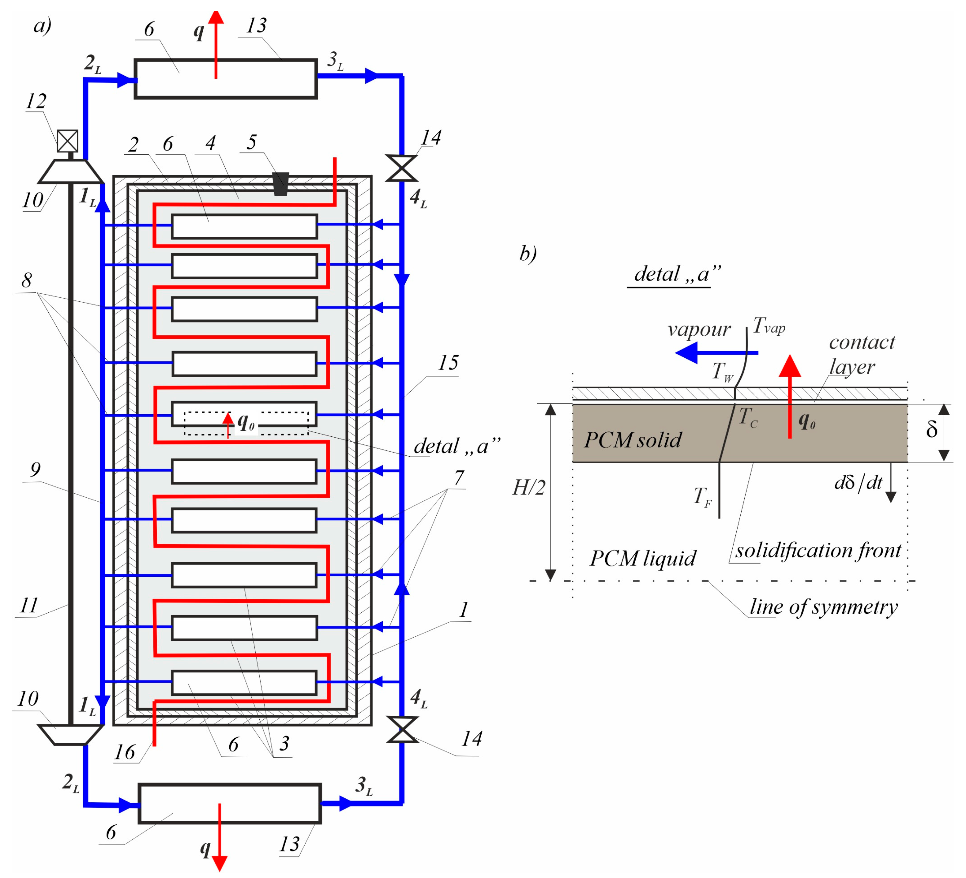
Figure 1 shows how they work together.
Figure 1a shows an example of the joint use of a heat accumulator and a heat pump. The heat accumulator is a closed tank (1), which is covered externally with an insulating cover (2) made of heat-insulating material. Inside the container are vaporisers (3) arranged as densely as possible, surrounded by phase change material (PCM) (alternating solid and liquid) (4). These repeating elements are the components of the accumulator. The phase change liquid material is poured into the tank (1) through the filling plug (5). Inside the vaporisers, a low-boiling-point thermodynamic medium flows (6). Each has inlet tubes (7) and outlet tubes (8) exiting through openings in the container and insulating sheath. The outlet tubes are connected to an outlet pipe (9), which connects the inputs to two compressors (10) mounted on a common shaft (11) driven by an electric motor (12). The outputs of the compressors are connected to the condensers (13), which are connected to the inlets of the corresponding throttling valves (14). The outputs of the throttling valves are connected to each other by an inlet pipe (15), to which the inlet pipes of the vaporisers are connected. Excess heat is supplied from the outside by means of a coil (16), through which hot water flows. The combined vaporisers, compressors, condensers and throttling valves constitute a heat pump that implements a left-handed thermodynamic cycle using a low-boiling-point thermodynamic medium [
27].
The heat from the accumulator is stored in the PCM (4) (which might include
n-Octadecane, stearic acid or wax). When absorbing heat from the accumulator, the PCM undergoes a solidification process, and when releasing heat, the material undergoes a melting process. The flow of a low-boiling-point thermodynamic agent in the pump system is forced by compressors (see
Figure 1a). The solidification temperature of the PCM is higher than the evaporation temperature of the low-boiling-point thermodynamic agent (which might be propane);
(see
Figure 1b). As it passes through the evaporator, the low-boiling-point medium absorbs the solidification heat of the phase change material and evaporates. Afterwards, through the compressors, the low-boiling-point thermodynamic medium flows at a high pressure through the condensers, where it is liquefied at a temperature of
. The condensers are in the form of heat exchangers, in which the low-boiling-point thermodynamic agent releases its heat to the secondary space heating circuit. From the condensers, the low-boiling-point thermodynamic agent flows to the throttle valves, where the pressure is reduced to that in the vaporizer. The energy used to compress the low-boiling-point thermodynamic medium by the compressors is very small in relation to the amount of heat absorbed by the condensers.
The process of charging the accumulator is done by melting the PCM by means of hot water supplied from the outside of the heating coil (see
Figure 1, designation 16) at a temperature higher than the melting temperature of the PCM.
The method of releasing the accumulated phase change heat, which is based on the use of the phenomena of material solidification and the simultaneous vaporization of the thermodynamic medium causing the thermodynamic change in the vapour refrigeration cycle, is characterized by the fact that the low-boiling-point thermodynamic medium accumulating the flow heat vaporizes inside the small tanks placed inside the PCM.
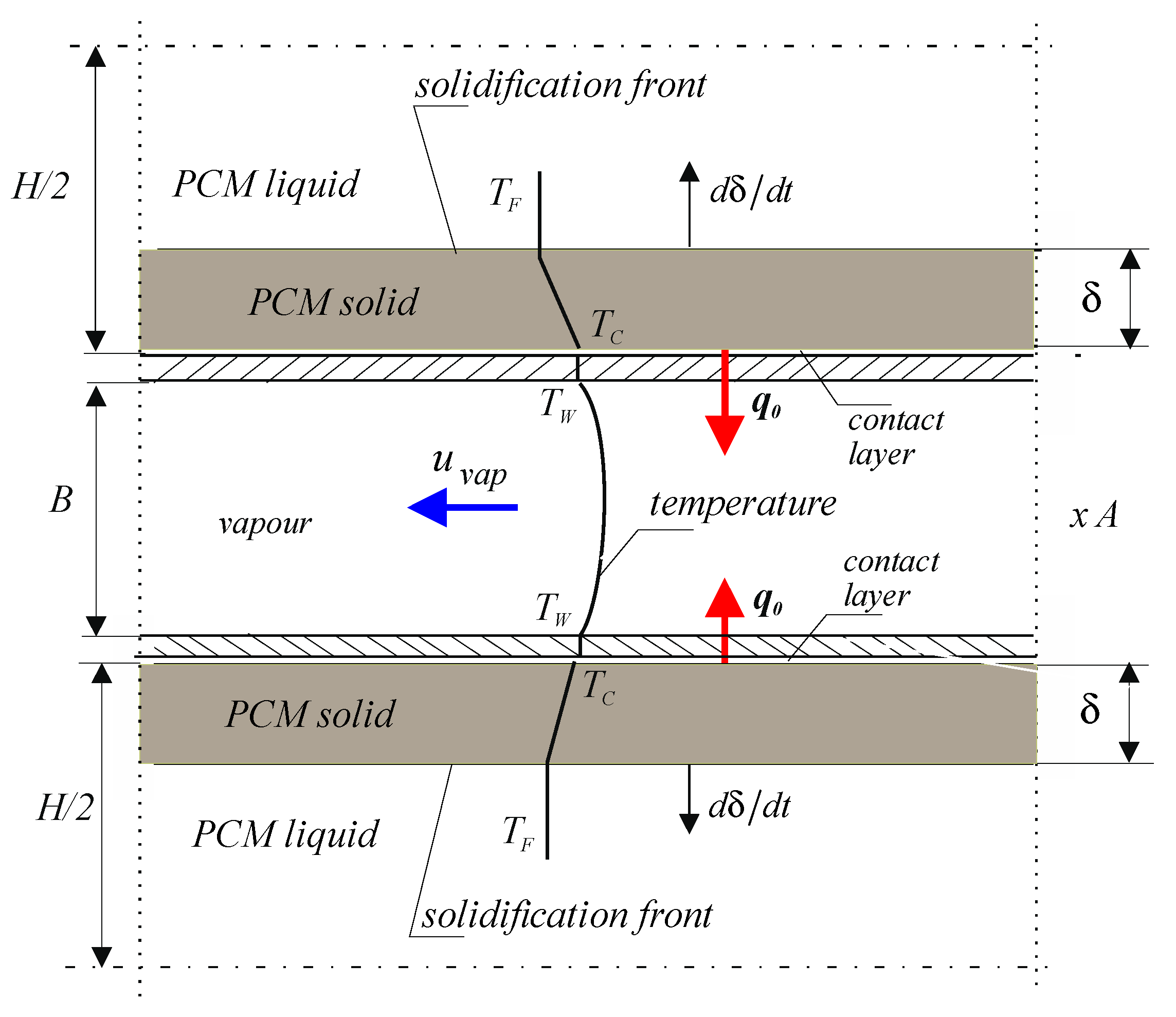
Figure 2 shows a schematic of the evaporator with transverse dimensions: A, B and length
l. Inside the evaporator, a refrigerant flows at a velocity of
and a temperature of
The evaporator is surrounded on the outside by a solidifying PCM. The refrigerant receives heat from the inner surface of the evaporator at a temperature of
. The heat transfer coefficient between the flowing fluid and the evaporator surface
is very important and decisive for the transferred heat flux from the inner wall of the evaporator. The transferred heat flux is described by the fourth term of Equation (1). In this work, the value of the heat transfer coefficient
) was assumed using the literature [
31] and the heat transfer coefficient in the contact layer
. We would also like to point out that it is very difficult to precisely determine the heat transfer coefficient. This parameter is not a material constant but depends on the phenomenon.
The presented analysis should contribute to the implementation of the patent [
27].
3. Theoretical Model of PCM Solidification
Figure 1b and
Figure 2 show the solidification one-dimensional model of a flat liquid layer of PCM with a thickness of
, cooled from the right side by vapor liquid flowing at a temperature
at a velocity
in the vaporiser. A very small gap, called the contact layer, is formed between the plate made at the temperature
of a very good conductor (for example, copper) and the surface of the solidified PCM, which creates additional resistance to heat flow
. The resulting gap is in contact with the lower solidified layer which has a temperature of
. A solidified layer of thickness
develops on the plate. The non-solidified liquid layer with a thickness of
decreases with time
.
The solidification process is very slow, which is why it is described by a quasi-stationary model. By design, the liquid PCM is not overheated; this means that the temperature of the liquid is equal to the freezing point. This assumption is justified by the fact that the solidification heat is much greater than the capacity heat. Such a simplified description of the solidification phenomenon justifies its relatively long duration [
28,
32]:
The first term of the above equation represents the heat of the phase change (the solidification of the liquid) at a temperature of , where is the density of the solidified layer, is the heat of solidification and is the solidification velocity. The second term of the equation represents the heat flux flowing through the solidified layer where is the heat conductivity of the solidified layer. The third term represents the heat flux flowing through the contact layer with the heat transfer coefficient . The fourth term represents the heat flux transferred by the cooling vapor flow with the heat transfer coefficient .
After the appropriate transformation of Equation (1), the equation of the heat flux balance was obtained as follows (eliminating temperatures
and
from Equation (1)):
Equation (2) can be replaced by the following dimensionless equation:
By introducing dimensionless quantities into the above equation system, the thickness of the solid layer is ; the time is , where is the Fourier number, is the Stefan number, where is the specific heat of the solidified layer, and is the heat of the solidification of the liquid; is the thermal diffusion coefficient of the solidified layer, where is the heat conductivity of the solidified layer, and is density of the solid layer; and is the Biot number in the contact layer, and is the Biot number on the surface of the plate of the evaporator.
The differential equation of Equation (3) should satisfy the following initial condition:
The solution of Equation (3) is the following function:
By solving the above quadratic equation, we can define the solidified layer thickness:
and differentiating Equation (6) with respect to time, the solidification velocity can be obtained:
This equation allows us to indirectly determine the heat flux generated by the solidifying PCM.
The above simple equations, Equations (5)–(7), are the same as the previously obtained solutions in previous works [
28,
29,
32] of the author of this work. The above equations are very convenient to use in numerical calculations. Numerical calculations are presented below for the following parameters:
[
16],
. The presented dimensionless parameters result from the use of various new ecological materials, such as Rubitherm RT64HC (wax) and R290 (propane).
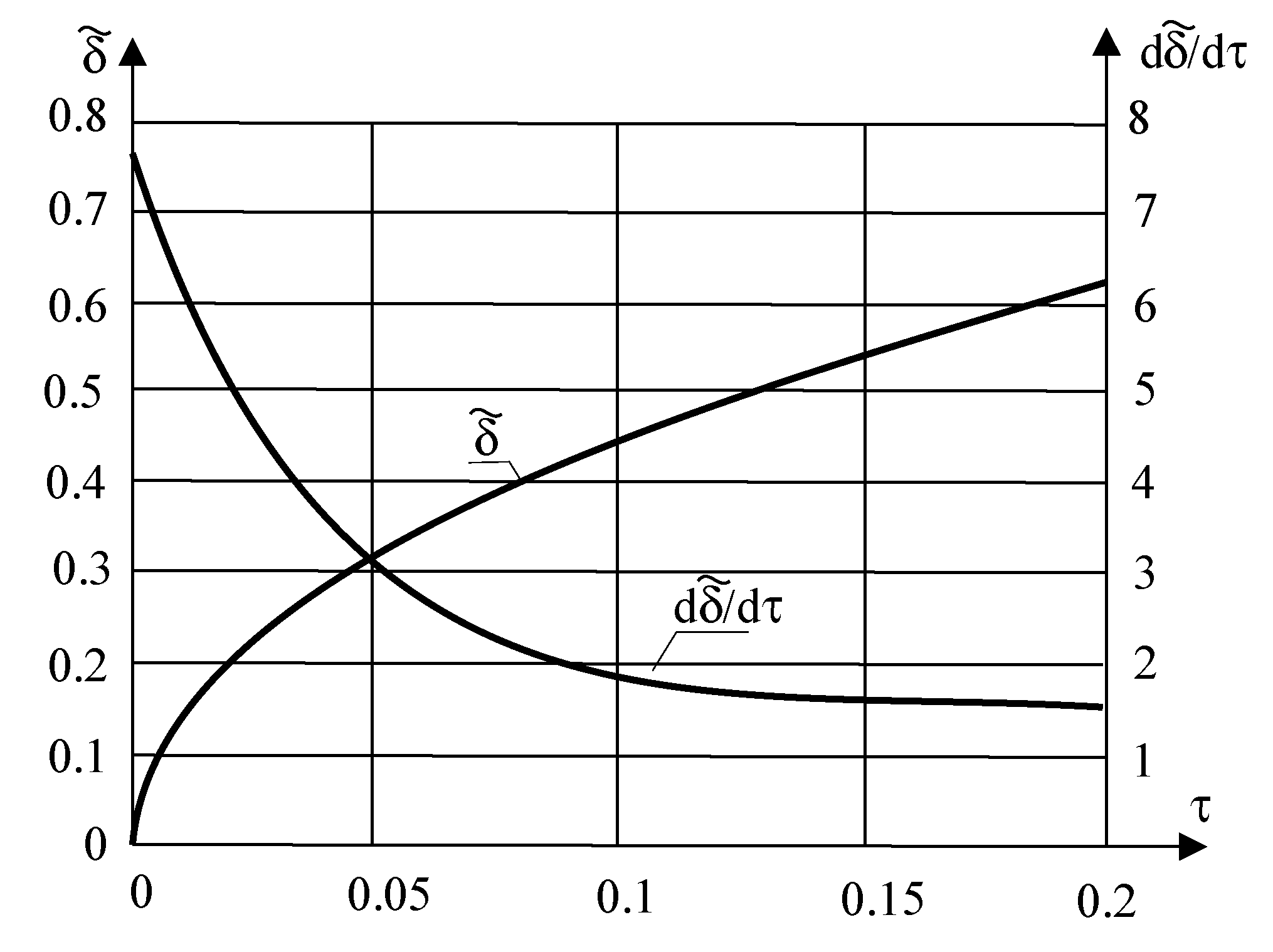
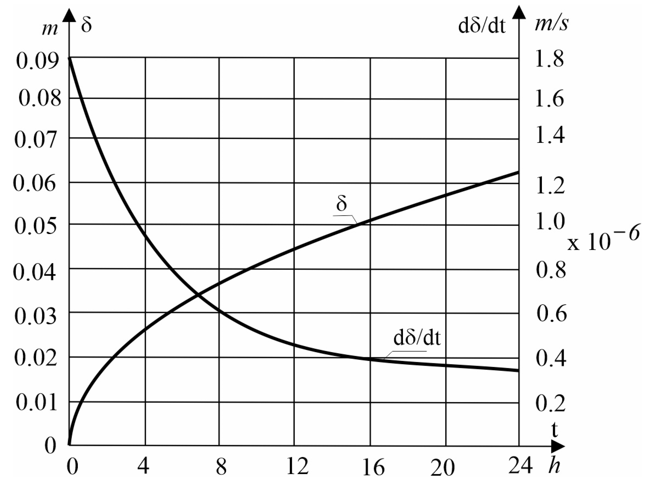
As can be seen in the above figures (
Figure 3 and
Figure 4), the thickness of the solidified layer
increases while the solidification rate
decreases with time
. The reason for this fact is the increase in the resistance to heat flow through the solidified layer with time.
4. Example of a Thermodynamic Cycle of a Compressor Heat Pump (SPC) and Solidification PCM
The heat accumulator uses PCM to store heat. When heat is taken out of the heat accumulator, the material changes from a solid to a liquid. When heat is put in, it changes from a liquid to a solid. Compressors force the low-boiling-point thermodynamic medium
R290 into the heat pump (
Figure 4).
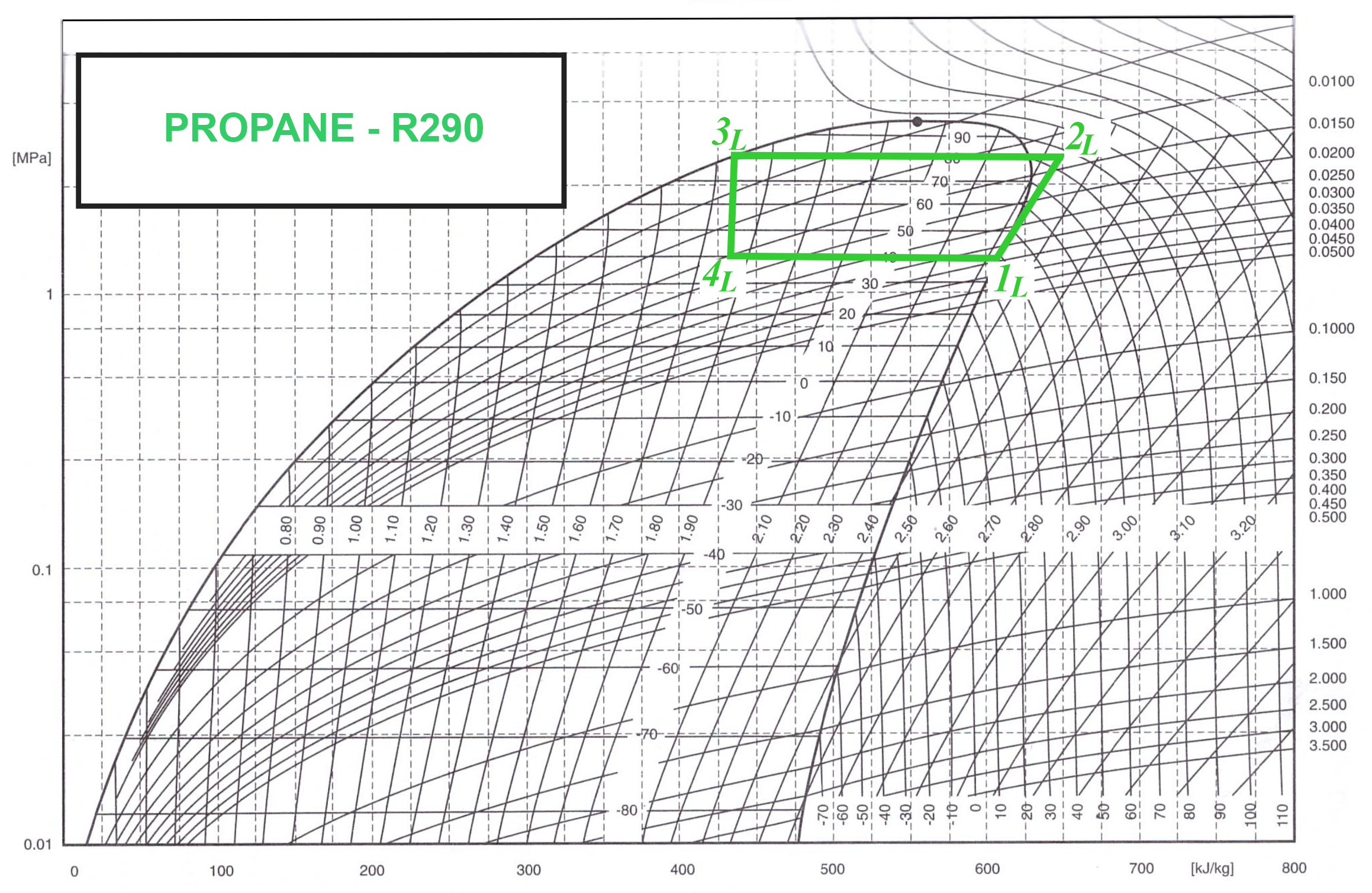
Figure 5 shows the Linde cycle, in which the
transformation is an isentropic compression of a thermodynamic medium (refrigerant R290) by the compressor from a pressure of
and a temperature of
to a pressure of
and a temperature of
. Adiabatic compression takes place at an entropy of
. Then the
thermodynamic transformation is isobaric. At the beginning of this transformation from a temperature of
to a temperature of
, the vapour superheat is removed isobarically. Then the condensation process of the refrigeration medium starts with a pressure of
. In this transformation (
), heat is transferred outwards for heating. For the
transformation is irreversible, due to the use of an expansion valve, which employs a throttling process in which the enthalpy remains constant. The transformation is an isenthalpic process of the refrigeration vapour to reduce the pressure from
to a pressure of
and the temperature from
to
. The
transformation is the final transformation of the Linde cycle. It is an isobaric and isothermal evaporation of a thermodynamic medium (
,
) during which heat is extracted from the solidifying PCM.
The Rubitherm
®RT64HC [
34] used the following thermophysical parameters for the PCM of the accumulator: solidification heat,
; thermal conductivity coefficient,
; density of solid,
; density of liquid
; specific heat capacity
; and heat diffusion coefficient,
.
As a thermodynamic refrigerant for the heat pump,
was used, whose properties are presented according to the Mollier diagram (see
Figure 5). The refrigerant
R290, commonly known as propane, is an organic chemical compound in the saturated hydrocarbon group. Its presence in natural gas reserves makes it readily available and economically attractive in the refrigeration industry.
R290 has many advantages that contribute to its popularity. Propane is a non-toxic, environmentally friendly gas. It has an ODP of zero, which means it does not damage the ozone layer. It also has a global warming potential of only three, which is significantly lower than other common refrigerants. Propane has a flammability limit of 2.1% by volume in air, making it safe to use. The flammability limit of propane is 40% higher than that of a propane–butane mixture, making
R290 safe to use in confined spaces. In regards to thermodynamic efficiency,
R290 has excellent thermodynamic properties, which translate into efficiency in refrigeration and air conditioning equipment. As a result,
R290 is a compliant and promising substance that can help reduce greenhouse gas emissions in the future.
Table 1 illustrates the dimensionless total time
of the solidification of the PCM, which can be calculated using Equation (5) for the Rubitherm
®RT64HC PCM. This is then compared to the actual time
, the heat of solidification for each evaporator
, the average heat flux for each evaporator
, the mass flow through one evaporator
, the average heat flux for each condenser
, the compressor power
and the coefficient of performance
.
We found the following enthalpies:
,
from the we Mollier diagram (see
Figure 5 or table in [
31]).
5. Discussion
As can be seen from the numerical calculations carried out in this work, the joint use of a heat pump and a heat accumulator is an interesting technological proposal. In times of surplus heat, they can be used to charge the heat accumulator by melting the PCM, and then in times of heat deficiency in the accumulator, the PCM is subjected to a solidification process. This process releases heat which is transferred to the evaporator of the compressor heat pump. The Linde cycle is then implemented in the SPC, where the condensation process in the condenser releases the condensation heat at a temperature adapted to the heating requirements. The phase change processes of melting and solidification are repeated cyclically. This work included detailed calculations of the solidification process of the PCM (the heat release process). The system of the joint components of a heat accumulator and a heat pump favours the use of excess heat, which affects its ability to save energy and stable operation. The heating temperature is constant and can be adapted to heating needs.
Designing a joint system of a heat accumulator and a heat pump is a very important task. The selection of the mentioned parts of the accumulator is one of the main tasks for the engineer or designer. The design of the joint system consists in selecting the appropriate PCM according to its phase change heat (solidification heat) and phase change temperature (solidification temperature). Selecting the spatial geometry of the PCM components undergoing phase changes (flat elements, spherical elements, ring elements and others) is also a very important task. Available PCMs in practice are usually poor heat conductors, which extends the duration of phase change processes. The appropriate external shape of the PCM affects the duration of phase changes and thus indirectly the heat flux released, i.e., the power of the accumulator. The heat flux released from the accumulator decreases with time because the thermal resistance of the solidified layer increases with the increase in its thickness (for solidification).
The selection of the thermodynamic medium, which should be ecological, such as
R290, and of the parameters of the compressor heat pump results from one’s heating needs. The coefficient of performance (COP) of heat pumps depends primarily on the condenser and evaporator temperatures (see
Table 2). The efficiency of the pump and the whole system increases when using surface heating, which has a lower temperature. Therefore, the use of a heat pump is most beneficial for surface heating, which does not require a high heating temperature.
The following is an example of the numerical results (Rubitherm ®RT64HC):
- -
Total solidification time:
- -
and the corresponding real time is as follows:
- -
- -
Average heat flow per evaporator:
- -
Mass flow through one evaporator:
- -
Average heat flux released in the condenser:
- -
- -
Coefficient of performance of the heat pump:
A theoretical analysis is performed for two examples of heating with a compressor heat pump using the Linde cycle for the refrigerant R-290 (propane): high-temperature heating at a temperature of 80 °C and low-temperature (surface) heating at a temperature of 60 °C, with the same unit heat output of 0.376 kW taken from the lower-temperature heat source. This heat is generated by the solidification of the PCM. The compressor power
per evaporator is 77 W in the first case and 40 W in the second case (see
Table 2).
A very important parameter characterizing the operation of a heat pump is the COP conversion parameter, defined by the equation
. The values of this parameter for the two different cases considered above for heat pump operation, extracting heat from the solidifying PCM, are given in
Table 1 and
Table 2.
Table 2 above also shows that with the same heat supply to the lower-temperature heat pump source
, when heating at a temperature of
(see the first row,
), the coefficient of performance is much smaller than when heating at a temperature of
(see the second row,
).
The joint use of the two main elements of the system considered in this work that incorporates a heat pump and a phase heat accumulator, in which a phase change (solidification) takes place, is very beneficial for heating various rooms. The heat pump allows for the very precise regulation of heating temperature (see
Figure 4), which corresponds to the condensation temperature of the thermodynamic medium in the condenser. The condensation temperature depends on the type of medium and the set operating conditions for the heat pump, i.e., it depends primarily on the compressor’s compression pressure. The precise setting of the heating temperature can be regulated by changing the compression pressure of the thermodynamic medium. The temperature increase from the solidification temperature of the PCM to the condensation temperature of the thermodynamic medium may be small, so the corresponding use of energy to drive the compressor is also small. As is known, surface heating does not require a high temperature. The effect of the heating temperature on COP is shown in
Table 2. The PCM undergoing a phase change, depending on its properties (the solidification temperature), affects the temperature occurring in the evaporator in a stepwise manner, and the selection of PCM is also very important.
To sum up, the joint use of a compressor heat pump and a phase heat accumulator is a very advantageous design solution for heating purposes.
6. Conclusions
Our theoretical analysis together with the numerical calculations and the discussion presented fully justify the concept of the joint use of a heat accumulator and a heat pump presented in this paper. The main advantages of this concept are energy savings and the stable operation of the system. Finally, it contributes to the protection of the environment and provides financial benefits. It is very important to choose the right PCM due to the impact on the environment.
The use of a heat pump is most beneficial for surface heating (underfloor, ceiling, or wall heating), which does not require a high heating temperature. Choosing a PCM, the following should be taken into account: the phase change temperature (solidification/melting), the phase change heat and the impact on the environment.
