1. Introduction and Motivation
The most common type of ignition of the air–fuel mixture in Otto engines is from the primary ignition source, which is an electrical discharge between the spark plug’s electrodes. A high concentration of energy characterizes this process and has been used since the beginning of SI engines’ existence. The development of ignition systems is aimed at increasing the energy generated in the electric arc mainly by modifying coils and spark plugs, which is particularly important in the combustion of lean, difficult-to-ignite mixtures.
Already, preliminary studies of publications and research work in the last ten years have shown that in the SI engines, both reducing the emission of THC, CO, and PM and reaching higher engine thermal efficiency are possible to achieve by operating on lean or intensively stratified mixtures.
In the case of hydrocarbon fuels (liquid and gaseous), the energy-efficient process requires several prerequisites: appropriate preparation of the combustible mixture and its appropriate distribution in the combustion space (e.g., charge layering), proper initiation of chain reactions of hydrocarbon particle decomposition, and initiation of oxidation processes of carbon and hydrogen particles contained in the fuel, and then controlling their course by using an appropriate supply reaction zone. In such cases, properly initiating and intensifying the combustion process requires a much higher activation energy to be delivered to the mixture during its ignition. This task requires applying a more efficient ignition system, which will deliver higher electrical discharge energy to the cylinder charge. While the authors have been working on the problems of two- or three-stage combustion in SI engines in recent years, the question of operating a spark-ignition system has become of significant interest [
1,
2,
3,
4].
The main area of the authors research interest in these studies has become the spark ignition system, which is significantly responsible for the efficiency of the combustion initiation process, especially of lean gas–air mixtures. In liquid fuel engines operating on lean mixtures, fuel is injected near the spark plug; such a procedure for gaseous fuels is much more difficult [
5].
The initiation of combustion of lean mixtures with a significant excess of oxygen (air) is strongly hindered because it requires a relatively high initial energy supply (activation energy). In SI engines, this energy is supplied by an electrical discharge on the electrodes of a spark plug powered by an ignition coil, which converts the low voltage supplied from the battery into the high voltage necessary to generate a spark. Knowledge of the efficiency of the ignition coil can be useful information for the potential further development of ignition systems of this type. Knowledge about the relationship between the coil charging time and the impact of ambient conditions, such as charge pressure and temperature, on the parameters of the electrical discharge, can also provide important information about the operation of spark ignition systems and their impact on spark energy, and will allow us to select the appropriate ignition parameters. This is why it was decided to conduct an experiment in this work: to determine the efficiency of the ignition coil depending on its charging time and to examine the parameters and factors on which the energy of an electrical discharge depends.
2. Present State of Knowledge on Ignition System Concepts and Applications
Over the many years of existence of spark-ignition engines, different systems have been developed with varying degrees of complexity and efficiency. One of the earliest, because it dates back to the end of the nineteenth century, and the simplest system, was the magneto ignition; one of the first applications is attributed to Edward Butler (1862–1940), who used the so-called magneto ignition in his engine in 1888. However, more often talked about is the first practical high-tension magneto developed by Frederick Richard Simms, working with Robert Bosch. In such a system, high-voltage pulses are generated due to the rotation of the metal core in a magnetic field, and the interruption of the primary circuit induces a current in the secondary circuit, causing a flashover of a spark on the spark plug electrode. Although such a system does not require a heavy battery of electric charge and is quite reliable, it produces only small discharge energy, especially at low rotational speeds, and the phenomenon of sparking (energy dissipation) occurs, requiring the use of a capacitor in the secondary circuit [
6,
7]. A few years later, ignition magnetos were used on most cars for both low-voltage systems (which used secondary coils to fire the spark plugs) and high-voltage magnetos (which fired the spark plug directly, similar to induction coil ignition). Ignition coils largely replaced ignition magnetos once batteries became common in cars, since a battery-operated coil can provide a high-voltage spark even at low speeds, making starting easier.
The use of a capacitor in the system was associated with the creation of a capacitor ignition system CDI (
capacitor discharge ignition). In such a system, the ignition spark is produced by the current generated by the discharge of the capacitor. When it is necessary to create a spark, high-voltage electrical energy is transferred to the primary winding of the coil, which in this system acts as a pulse transformer, not an energy storage device [
8]. The electric spark produced in this way has a high intensity but is short-lived (about 0.1 ms), so it does not provide reliable ignition for the lean fuel–air mixtures used in more and more modern engines [
8]. Since the charging time of the system’s electrical capacity is not dependent on the engine speed, there is no need to use ignition advance angle control. This system is, therefore, used in small high-speed combustion engines.
In contrast to systems with point ignition of combustion, surface ignition solutions have also appeared. For example, a hot-tube ignitor was a device from the early 1900th that fit onto the cylinder head of an internal combustion engine and was used to ignite the compressed fuel–air mixture by means of a flame heating part of the tube red-hot. A hot-tube ignitor consisted of a metal or porcelain tube, closed at one end and attached to the cylinder head and an adjustable burner that could be moved to position its flame at any point along the length of the tube. In early designs, ignition timing was controlled by adjusting the position of the red-hot spot on the tube—this was accomplished by moving the burner along the length of the tube. Most later styles used a fixed burner and varied tube lengths to change the ignition timing [
9].
In the search for combustion systems with increased energy efficiency, attempts were made to use the combustion of lean fuel–air mixtures, but initiating combustion under conditions of fuel deficiency in the mixture requires a significant increase in the initial energy, the so-called activation energy. The concept of combustion of such mixtures in aircraft engines was worked on in the 1950s by Nikolai Semenov (Russia), and later its use in internal combustion engines was carried out by Lev Ivanovich Gussak who constructed the LAG system (
Lavinia Aktivatisia Gorenia or
Avalanche Activated Combustion) [
10,
11,
12,
13]; The concept created at that time was often referred to as spark-jet ignition.
Similar ignition systems have been studied in Japan (Honda CVCC, Toyota TGP, Nissan NVCC, Toyota TGP), Germany (Porsche SKS, Volkswagen PCI, PCV, Daimler-Benz TSC), and England (BLMC). In the 1980s, research was carried out in Japan on the effects of different sizes of pre-chambers and the channels connecting them to the cylinder [
14]. It was then found that the ignition of lean mixtures is most effective due to composite ignition [
14]. The interaction of free radicals and thermal phenomena achieved ignition. The ignited mixture (propane–air) in the pre-chamber had approximately the value of λ = 0.91, and the lean one in the cylinder had λ = 2.4.
Jet ignition uses the ignition of a rich mixture in a relatively small pre-chamber, and the burning mixture is ejected with high energy into the main combustion chamber to ignite the lean or very lean mixture in it.
Among the jet ignitions, we can distinguish JPIC (jet plume injection and combustion) from others. It is a system that was created on the basis of PJC (
pulsed jet combustion) and developed by Prof. Antony Oppenheim (1915–2008) in Berkeley (USA) [
15,
16,
17,
18,
19].
The pre-chamber is built around a modified spark plug in the pulsed jet combustion system. According to the PCJ idea, the fuel, or air–fuel mixture, is delivered through a hollow injector electrode to a pre-chamber at the bottom of the combustion chamber. Some of the supplied mixture also gets into the cylinder, where the rich mixture (ca. λ = 0.85) and the residual exhaust gases from the previous cycle are located. At the end of the injection time, the rich mixture in the pre-chamber is ignited by means of a spark plug, which is then injected into the cylinder in the form of a stream, causing turbulence and further ignition and producing a large number of diffuse ignition centers, which result in a higher concentration of ignition energy and a short ignition time for lean mixtures, as the flames have a shorter travel distance. This type of ignition system differs from JPIC in that it uses high pressure generated in the pre-chamber rather than high-pressure injection. The advantage of pulsed jet combustion is a faster increase in pressure and a higher maximum pressure than in the case of ignition with a classic spark plug [
15,
17,
18].
The next stage in the development of lean-burn ignition techniques is HAJI, i.e.,
hydrogen-assisted jet ignition. This system uses hydrogen as fuel for the pre-chamber. The HAJI system is mounted to the spark plug hole. The HAJI module consists of a small pre-chamber, a spark plug, and a direct injector to the pre-chamber. To start the ignition, a small amount of hydrogen is injected into the pre-chamber, creating a rich mixture there. Then, a spark from the plug ignites the mixture. The burning rich mixture passes through the hole/channel into the main chamber at high velocity, where it ignites the lean mixture. The energy generated in the pre-chamber is more than two orders of magnitude higher than in the case of classic spark ignition [
14].
Lean-burn combustion allows for a lower combustion temperature, resulting in lower nitrogen oxide emissions and higher engine efficiency. It was found that it was possible to burn lean mixtures with an air excess coefficient from 2 to 5 [
14]. However, the low combustion temperature results in higher hydrocarbon emissions. There is also a similar combustion system referred to as HFJI (
hydrogen flame jet ignition). The research determined that turbulence is more important during ignition than larger radicals, which is why hydrogen streams with greater turbulence are used in this system [
14]. HAFJI enables combustion at a lower pressure and can provide a more stable process.
A swirl chamber spark plug is a type of spark plug with a small pre-chamber located inside the spark plug. During ignition, an engine equipped with this type of spark plugs has two fuel injections. The first injection forms a lean mixture (λ = 1.4–1.7) and takes place during the intake stroke. The second injection is much smaller (approx. 3% of the total fuel weight used), is directed directly at the piston crown, and takes place during the compression stroke. The movement of the piston pushes the fuel from the second injection into the pre-chamber of the spark plug, where a rich mixture is formed. Then, by electrical discharge, ignition occurs in the pre-chamber and the flame propagates into the cylinder, where the lean mixture is ignited. This technology has lower nitrogen oxide emissions, lower fuel consumption, and greater resistance to knocking under full load than a traditional spark plug.
A patent for a PCFA (
premixed charge forced auto ignition) engine was filed in 2003 by General Motors [
14]. In the ignition system, this type of jet of reactive air–fuel mixture passes from the pre-chamber to the main chamber, where it combines with the pre-mixed ultra-lean mixture. As a result of this process and the compression, rapid ignition and expansion begin. This ignition method is to be used only in the engine operating at low speeds, and at higher engine speeds, ignition is to take place conventionally. The advantages of this method are its higher efficiency and lower nitrogen oxide emissions.
The idea of HCJI (
homogeneous combustion jet ignition) is to control the moment of ignition in HCCI engines by means of jet ignition in the pre-chamber [
14]. There are two chambers attached to the cylinder, in which self-ignition takes place. The microvalves of the pre-chambers close near the beginning of the compression stroke and then, due to the action of the “pre-chamber pistons” located there, the pressure increases, and spontaneous ignition occurs. Then the microvalves open and a stream of hot gases ignites the mixture in the cylinder. The lack of an ignition spark in this technology is to eliminate uneven combustion.
A pre-chamber ignitor equipped with a pre-chamber fuel supply system was patented in 2006 [
14]. There is also a groove with a spark gap in the middle of the ignition. The device also has a second external spark gap directly into the cylinder. When the engine is running at low speeds, the rich mixture is ignited in the pre-chamber, and then a stream of active radicals is introduced into the main chamber, where the leaner mixture is ignited. When the engine is running at high speeds, ignition takes place without the use of an internal spark gap and without a fuel supply system to the pre-chamber; ignition is similar to ordinary spark ignition.
Homogeneous combustion radical ignition (HCRI) is used to ignite homogeneous mixtures. This system connects the main combustion chamber through narrow channels to additional compact chambers [
14]. A richer mixture is created in the small chambers, and radical ignition occurs. After entering the main chamber, the radicals initiate the combustion of a poorer homogeneous mixture.
Some other ideas exist for alternative and more effective initiation of the combustion process based on conventional ignition systems. Renault’s radio frequency ignition system (RFIS) operating with the traditional spark plug should be mentioned here. In this case, the input voltage produced by an external power source is amplified in the resonant circuit of the transformer. The best resonant frequency is 4.97 MHz. An alternating high-voltage electrostatic field causes ionization, excitation of electrons to high-energy states, and an increase in the number of free radicals. The fuel–air mixture ignites if the cylinder has the right physical and chemical conditions. This system does not require a second electrode and ignites a larger area than using standard spark plugs.
It was stated that the use of RFIS allows the duration of the spark to be varied according to the need resulting from the actual operation of the engine and that it is also more efficient in transmitting the ignition energy from the spark. The lack of limitations resulting from the distance between the spark plug’s electrodes, and the multi-channel discharge structure allows a larger area to be ignited with a spark. RFSI shortens the combustion duration, enables a higher rate of heat generation, and provides greater stability of the combustion process for loaded engines. Another observed effect of RFSI was an increase in engine efficiency by 1% to 5% and the ability to carry out the combustion process with leaner fuel–air mixtures. The use of RFSI also reduces the emission of HC and CO particles, while NOx emissions are higher than those of ignition with a standard plug, due to the higher peak temperature in the cylinder. Reducing NOx emissions with RFSI is possible by taking advantage of the ignition system’s ability to carry out the ignition process for leaner air–fuel mixtures.
3. Ignition of Lean Mixtures
Most ignition systems mentioned here are designed to initiate the combustion of lean fuel–air mixtures. A lean mixture is a fuel–air mixture in which the amount of fuel in relation to the air is less than in the stoichiometric mixture (λ > 1). Combustion of lean mixtures leads to an increase in the energy efficiency of the engine. It reduces the emission of harmful substances, especially nitrogen oxides, which results from decreasing the engine cylinder’s maximum temperature [
20,
21]. Excess air also promotes the oxidation of carbon monoxide and unburned hydrocarbons. It causes a reduction in the temperature gradient between the combustion products and the cylinder walls, which is equivalent to reducing heat loss to the walls. However, it should be remembered that if the mixture is too lean, the combustion process may not start, or it will be necessary to increase the ignition energy. The disadvantage of burning lean mixtures is a decrease in power per unit of engine displacement, a longer combustion time, and increased engine unevenness. It has also been shown that lean-burn engines respond much faster to even small changes in fuel composition.
The energy of spark ignition depends on the parameters characterizing the design of the spark plug used and the method of discharge on the electrodes. An important parameter resulting from the construction of the plug is the distance of the electrodes, which must be greater than the quenching distance. This is the distance of the walls of the vessel or duct below which the spread of flame is not possible due to the heat removal through these walls. The spacing should also be large enough to ensure that the mixture ignites during idling and at full engine load. It must also be small enough to ensure ignition in difficult conditions, such as cold electrodes, reduced ignition voltage, or a high compression ratio. The spacing between the electrodes depends on the type of motor in which they are used.
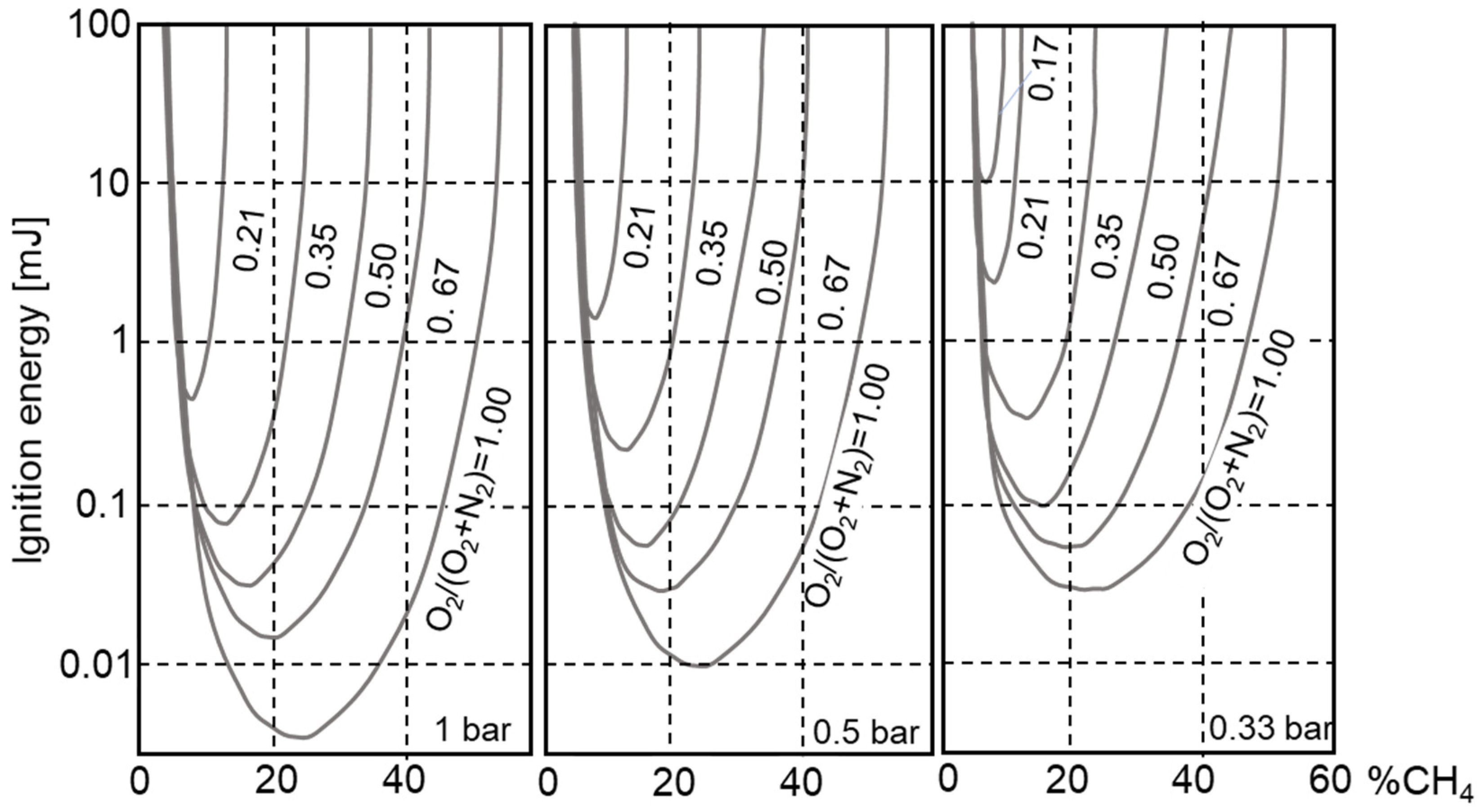
Some of the energy that was stored in the inductive ignition system is dissipated in the electrical system (losses), and the rest is released in the mixture. Its main form of distribution in the mixture is heat and as electromagnetic and acoustic waves. The aim is to achieve the shortest possible single discharge time. If the extinguishing distance is appropriate, the ignition energy mainly depends on the fuel–air mixture parameters (
Figure 1). The energy required for spark ignition of fuel–air mixtures used in internal combustion engines is less than 1 mJ. The ignition energy increases when there is a pressure drop, when the proportion of oxygen in the air decreases, the closer the composition of the mixture is to the upper or lower ignition limit, when the flow velocity increases, when the level and scale of turbulence in the mixture medium increases, the less similar the mixture is to the stoichiometric from whence it comes, and the lower the air temperature (for t < 0 °C) [
22,
23].
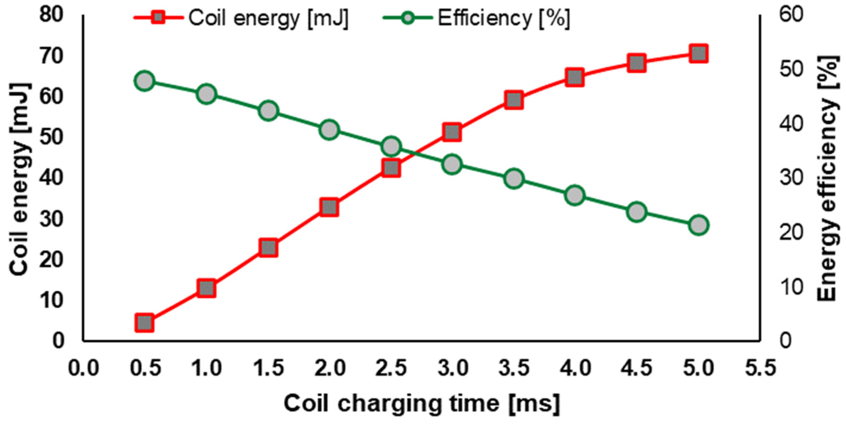
The required ignition energy should achieve values as great as 60–80 mJ for lean and very lean mixtures. Achieving such values requires both an increase in electrical energy in the primary circuit of the ignition system and an increase in the efficiency of converting this energy into spark discharge energy delivered directly to the ignitable mixture.
4. Research Problem and Scope of Investigations
Based on the literature studies, it was concluded that the energy flux’s efficiency in the ignition system has still not been sufficiently investigated and quantitively described. Therefore, it was considered necessary to conduct appropriate investigations that would enable a quantitative assessment of the ignition system’s effectiveness, especially for its appropriate configuration for the ignition of lean gas–air mixtures.
The main aim of the work has been defined as experimental identification of energy fluxes in the ignition system beginning with the electrical energy in the ignition coil up to the determination of the electrical arc flash and its light radiation resulting from flame initiation. It was planned to determine the energetic efficiency of the ignition system by comparing the electrical discharge energy with the energy delivered to the ignition coil’s primary circuit.
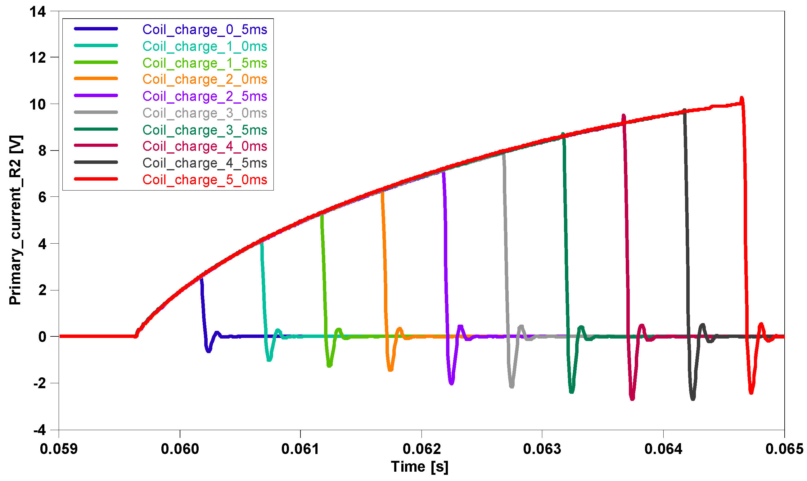
The tests were carried out in a constant volume chamber with a backpressure of 0, 5, 8, 10, and 12 bar for different current values (4.0 … 11.0 A) and various times of supply to the coil, i.e., t = 1.5, 2.0, … 5.0 ms. For the determination of electrical energy, both current (I) and voltage (U) in the primary and secondary circuit of the ignition system were measured and compared with the current determined on the ground electrode of the spark plug. These data allowed us to determine the electrical energy delivered to the coil and generated electrical discharge energy.
7. Summary and Conclusions
The research presented in this article focuses on the quantitative identification of energy flow at various stages of the spark ignition system. The study analyzes a modern solution based on an individual single-pole COP ignition coil from a direct injection gasoline engine. The amount of energy delivered by the controller to the coil, the energy generated by the ignition coil, the spark’s electrical energy, and the spark discharge’s initial stage were characterized.
The test results’ analysis enabled us to draw conclusions regarding the impact of changes in the coil charging time and pressure variations on the spark plug’s electrical discharge. This study addresses an existing gap in the understanding and analysis of this phenomenon.
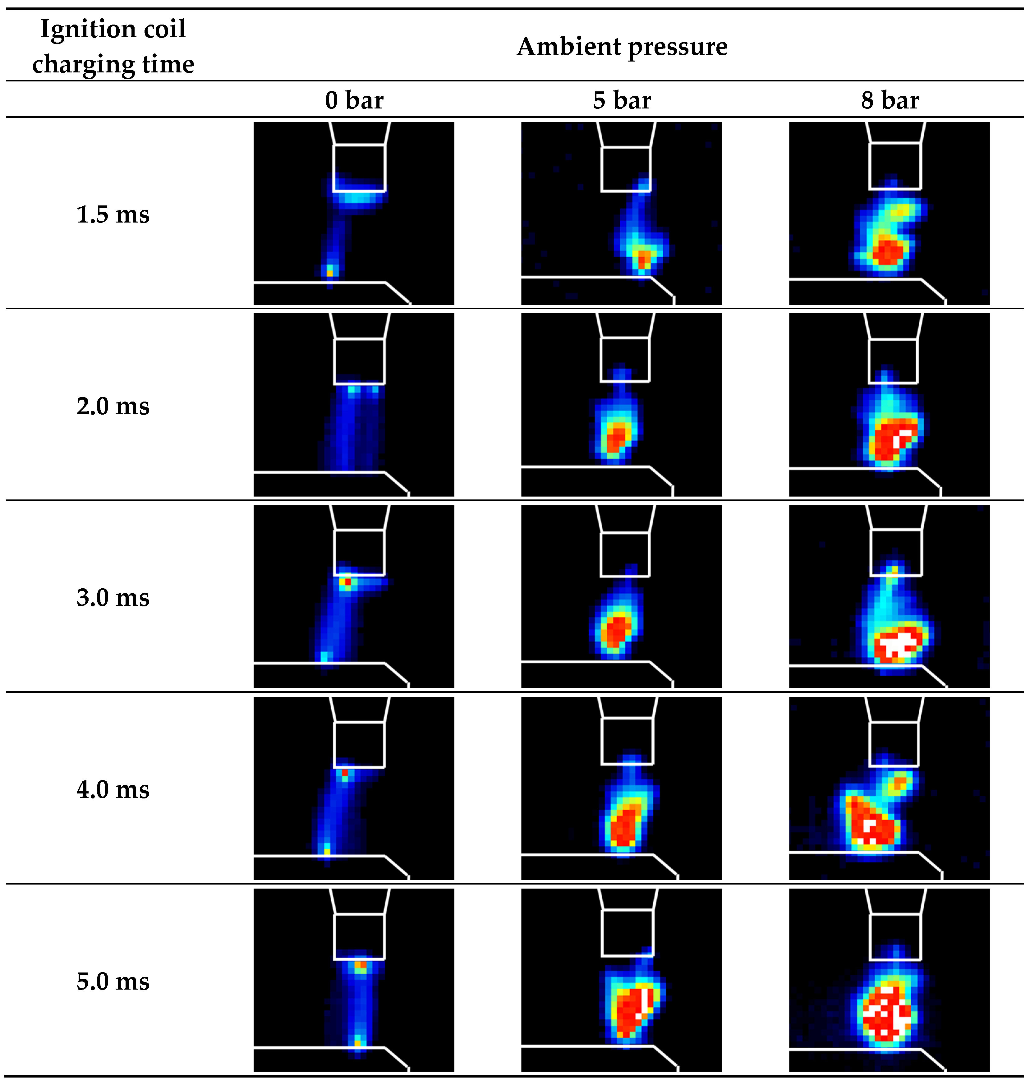
A nearly linear relationship was demonstrated between the energy delivered to the ignition coil and the saturation time. For a maximum coil charging time of 5 ms, the coil charging energy was 330 mJ, compared to 72 mJ of generated energy. As the charging time increases, the efficiency of energy conversion between the primary and secondary circuits of the ignition coil decreases. Therefore, controlling the charging time well below the saturation of the ignition coil becomes advantageous. It is important to avoid areas of ignition coil saturation. In an engine, the discharge frequency is high, so significant losses can be generated in general. The achieved efficiency ranges from 20% to 50%. The energy conversion efficiency from the ignition coil to the spark also increases with increasing ambient pressure and charging time, reaching 78%. Minimum values were recorded for no counter-pressure in the 38% to 48% range. Electrical data were correlated with discharge images. The increased discharge energy due to higher ambient pressure and charging time translates into an increased area covered by the electric arc. Above 5 bar of counter-pressure, there was no observed effect of charging time and further increase in counter-pressure on the average intensity of the electric arc luminescence.
During the experimental process, thermal energy from the discharge was not analyzed; however, without these data, significant losses can be assumed at each ignition system component.


