Article

Control of Liquid Hydrocarbon Combustion Parameters in Burners with Superheated Steam Supply

1
Kutateladze Institute of Thermophysics of the Siberian Branch of the Russian Academy of Sciences, Novosibirsk 630090, Russia
2
Department of Thermophysics, Siberian Federal University, Krasnoyarsk 660041, Russia
*
Author to whom correspondence should be addressed.
Energies 2024, 17(20), 5047; https://doi.org/10.3390/en17205047
Submission received: 4 September 2024 / Revised: 26 September 2024 / Accepted: 9 October 2024 / Published: 11 October 2024
(This article belongs to the Section I2: Energy and Combustion Science)

Abstract

:
A numerical simulation of reacting mixture flow in a full-scale combustion chamber of a prototype burner with a fuel-sprayed jet of superheated steam and a controlled excess air ratio was performed based on a verified model. The influence of steam jets on the combustion parameters of the created prototype device was analyzed based on the results, and a comparison with data from various atmospheric burners, including evaporative and spray types, direct-flow and vortex types, and those with natural and forced (regulated) air supply, was made. Various schemes for supplying steam to burner devices were discussed. It was shown that the relative steam consumption is a parameter for controlling the emission of toxic combustion products, such as NOx and CO, for all designs. A high burner performance is achieved when superheated steam is supplied at more than 250 °C with a relative steam flow rate of >0.6. The design features of the burner systems and operational parameters that ensure high thermal and environmental efficiency when burning various types of fuel and waste are identified.

1. Introduction

Liquid hydrocarbon fuels are the most efficient source of energy for vehicles and remote facilities due to their high specific heat release. Fuel efficiency is largely determined by combustion conditions. High-quality energy carriers, which determine the preferred direction of technological development, are usually used to reduce emissions of harmful combustion products [1,2,3]. This does not involve the use of non-project fuels (low-quality fuels or industrial waste). At the same time, the task of the efficient and safe utilization of hydrocarbon reserves becomes increasingly relevant.
The ignition stability and completeness of combustion of liquid hydrocarbons are determined by their quality of atomization and mixing, as well as by processes of fuel gasification [4]. These factors are essential when burning low-quality fuel residues that are characterized by a high water content, the presence of mechanical impurities, and a high viscosity [5]. In such conditions, pre-gasification is the most suitable solution to produce combustible gasses [6]. Pre-pyrolysis [7] is mainly used for light fuels, such as in devices [8,9,10,11,12]; it is not used for heavy fuels due to the risk of coke deposition [13].
The main products of gasification are synthetic fuel and synthesis gas [14]. Fuel production from oil sludge is possible through thermal cracking and catalytic pyrolysis [15,16,17]. It has been shown that the process is influenced by the addition of water vapor and ash [18]. Kinetic characteristics and other factors affecting the pyrolysis/gasification of oil sludges and the composition of the products are considered in [19]. Catalytic pyrolysis and joint gasification have been proposed to increase the efficiency of thermal conversions. In addition to oil sludging, attention has also recently been drawn to the gasifying of biomass [20,21]. Steam gasifying biomass is seen as a promising technology to produce synthesis gasses with high H2 contents, which can be used to synthesize liquid fuels and chemicals [22]. A study on the effect of agents on gas yield from corn straw was conducted in [23]. It was found that cross-linked carbon is more likely to be consumed during char gasification with H2O. Biomass gasification, including steam gasification, has a high potential to produce highly reactive fuels [24,25].
Despite significant advances in technologies for the gasification of low-quality fuels to produce combustible gasses, the practical implementation of this approach is associated with disadvantages, including high metal consumption, the need to control conditions inside the gasifier, and the need to maintain a stable composition of raw materials to ensure the predicted quality of the gas produced. These requirements are not imposed on partial gasification processes of liquid fuels. For example, an evaporative burner device uses superheated steam generated directly from the combustion chamber to gasify the products of fuel decomposition [26]. The operation of the devices [27,28,29,30,31] is based on a similar principle. Experiments [26] have recorded concentrations of OH radicals exceeding equilibrium values. This ensures the intensive combustion of “heavy” fuels and a low soot content in the combustion products. These results have sparked interest in studying hydrocarbon combustion in a jet of superheated steam, including solving problems with recycling low-quality fuels and industrial waste. Other studies using various burner devices with the partial gasification of evaporative [32,33] and spray types of direct flow [34] and vortex [35], with both a natural [36] and a forced (regulated) air supply [37] have found that steam affects the size, temperature, and radiation spectrum of the flame, as well as the carbon monoxide and nitrogen oxide content in combustion gasses. The obtained dependencies of liquid hydrocarbon burning indicators on control parameters make it possible to optimize energy generation technologies using low-quality fuels and waste.
The aim of this study is to generalize the findings regarding the impact of a steam jet on the combustion characteristics of a liquid hydrocarbon mixture with partial gasification. Based on the experimental data obtained through the use of a prototype burner device that sprays fuel with a steam jet and has a controlled excess air ratio [38], mathematical modeling was conducted to investigate the changes in steam consumption. The results were compared with those obtained from atmospheric burners that employ partial gasification to determine parameters for controlling toxic combustion product emissions (NOx and CO) in these types of burners. It forms the basis for further research into the ignition and combustion processes of various hydrocarbon fuels in large-scale firing stands with a wide range of operating conditions. Such research will allow for the development of neural network models for monitoring combustion indicators in industrial settings.

2. Methods and Materials

A numerical simulation of the low-emission combustion of liquid hydrocarbon fuels with partial gasification was conducted in a full-scale, stationary setting. The mathematical model was validated based on experimental data obtained from a prototype burner device that utilized steam jet fuel spraying (Forced draught Direct flow Spray burner, FDS) at an experimental facility based on a Vitola 200 hot water boiler (Viessmann GmbH, Allendorf (Eder), Germany) [38]. The burner device, developed based on a direct-flow, adjustable primary air supply spray burner design (see Section 3.2.2 Direct-Flow Spray Burner with Regulated Air Supply to the Gas Generation Chamber), was implemented in a horizontal configuration (see Figure 1). In atmospheric burners, combustion occurs in an external flame in uncontrolled conditions of mixing with an oxidizer from the environment. However, in the case of a closed chamber, a secondary airflow with an adjustable rate is supplied at the base of the burner torch.
The use of a closed combustion chamber made it possible to obtain experimental data on the effect of excess air on the combustion characteristics of fuel and the products of the partial steam gasification and incomplete oxidation of fuel, which are formed in the gas generation chamber. It is shown that with a ratio of primary air consumption to a stoichiometric value of no more than 0.3, the production of CO and NOx for diesel fuel is 30 mg/kWh and 85 mg/kWh, with secondary air consumption of no more than 0.9 of the stoichiometric value. The coefficient of excess air does not exceed 1.2 in total, which satisfies the existing regulatory documents [39]. The achieved thermal and environmental indicators demonstrate the prospects of the method of burning liquid hydrocarbons by spraying with a superheated steam jet in the developed burner devices for solving the practical problems of thermal energy production using non-project fuels at small-scale energy facilities.
Figure 2 shows the central section of the burner and boiler volume. The calculations were carried out in the Academic version Ansys Fluent 17.1 package on an unstructured polyhedral grid of 5.4 million cells (Figure 2) with condensation in the area where the processes of the evaporation, ignition, and combustion of fuel are intensively occurring (the flame formation zone); additionally, a discrete droplet size distribution (typical for injectors) and the spray angle of the dispersed jet were set.
To describe the physicochemical processes of the combustion of hydrocarbon fuels in the combustion chamber, a complex mathematical model was used. This model included a model of the motion of a multicomponent, non-isothermal gas medium, based on the k-ε SST RANS approach, as well as a model of the combustion in the gas phase, based on the EDC (Eddy Dissipation Concept), including a reduced mechanism consisting of 60 chemical reactions and 35 components. The movement of droplets was described using the Lagrange method, and the method of discrete ordinates was used to solve the equation for thermal radiation transfer. Absorption coefficients of the medium were calculated using a gray gas sum model, and n-heptane (C7H14) was used as a design fuel. A description of the mathematical modeling technique can be found in [40].

3. Results

3.1. Numerical Simulation

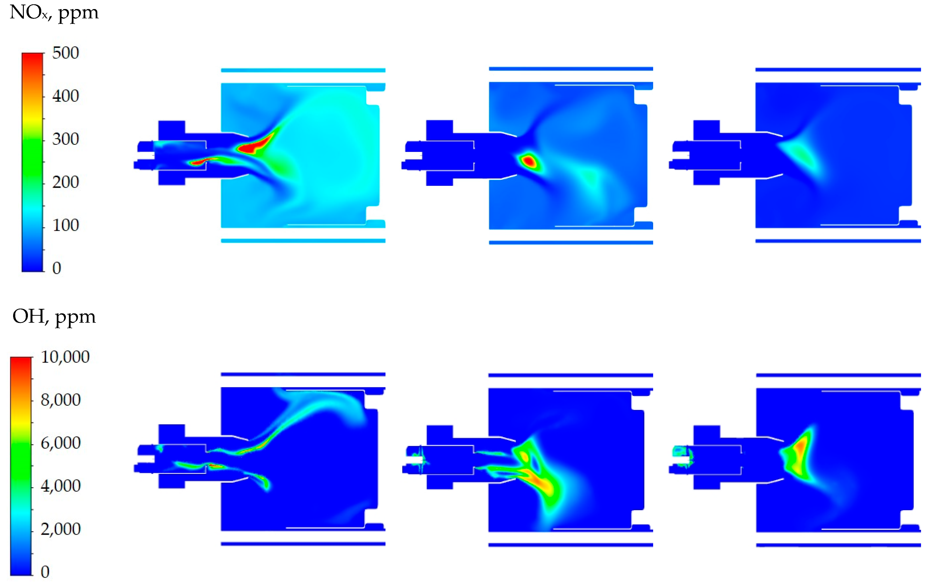
Numerical simulation was performed for modes with a fuel consumption of 3.0 kg/h and an excess air coefficient of 1.35. Relative steam consumption varied from 0.02 to 0.5, similar to the modes studied in [38]. The results of numerical modeling showed that the relative steam consumption had a significant effect on temperature and concentration distributions of substances. At low values, the flame became more stretched, while at higher values, it was localized near the burner nozzle due to the more intense oxidation of the fuel inside the gas generation chamber of the burner. With decreasing relative steam consumption, NOx and CO concentrations increased, affecting their content in the final combustion products, and increasing the underburning of the fuel (see Figure 3 and Table 1). In [40], it was noted that adding steam significantly affected the intensity of certain processes in the combustion chamber. For example, the decomposition of high-molecular-weight hydrocarbons—C7H16 + H = C7H15 + H2 and C7H15 = C2H5 + C2H4 + C3H6—slows down, and the production of reaction products involving the OH radical significantly increases.

3.2. Comparison with Experimental Data on Atmospheric Burners with Partial Gasification

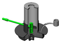
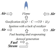
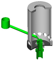
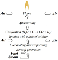
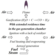
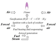
This section describes various combustion schemes with a steam supply to the reaction zone implemented in laboratory models of burner devices. The designs of the burner devices created and the steam supply schemes used in them are shown in Table 2. Specific structural elements are marked in green on the graphic models. All burner devices operate according to the principle that they use a natural influx of air from the environment without the use of devices for the forced supply of the oxidizer.

3.2.1. Evaporative Burners

Evaporative Burner with Autonomous Steam Generation (EA)

In [32], studies were carried out on the effect of superheated steam on liquid hydrocarbon fuels and waste combustion processes using an autonomous evaporative burner with a capacity up to 20 kW and a built-in steam generator. The water volume was 1 L, the operating time was 3 h, the pressure was 5 atm, and the steam temperature at the nozzle outlet was 400 °C. This device provided a natural flow of air into the combustion zone from the atmosphere, eliminating the interaction of the steam jet with the liquid phase of the fuel. The burner was made of AISI 321 steel and had a vertical orientation. It could operate in a stationary mode and provide stable steam generation as well as the ignition of the fuel.
An important element of the burner device is a steam nozzle, which forms a high-speed superheated steam jet that ejects air from the environment and determines the structure of the external torch. The steam nozzle is made of stainless steel and has an outlet channel with a length of 4 mm and a diameter of 0.6 m, and its full opening angle is 20° [41]. The nozzle is connected to a steam generator installed coaxially at the base of a cylindrical gas generation chamber oriented vertically upwards. When the pressure is 5 atm, the Mach number at the outlet of the nozzle exceeds 1. Supplying a high-velocity superheated steam jet into a burner gas-generating chamber intensifies fuel vaporization, mixing, ignition, and combustion.
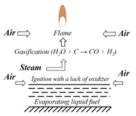
It has been established that the steam supply leads to the partial gasification of carbonaceous products from the thermal decomposition and incomplete combustion of diesel fuel, forming water gas (H2O + C = CO + H2) [32]. By reducing the amount of soot in the combustion products, the efficiency of fuel combustion improves. At the same time, a decrease in the emission of toxic combustion products has been recorded, whereby at 15 kW power, the production of CO and NOx is 15 mg/kWh and 95 mg/kWh, respectively, which meets the strictest environmental standards (class 3 according to EN 267 [39]).
Autonomous steam generation does not allow for control over the flow rate and temperature of the steam, which depend on the heat generation capacity in the combustion area. To study the dependence of the indicators on steam flow parameters, it was necessary to switch to a controlled steam supply from an external steam generator.

Evaporative Burner with Regulated Steam Supply (ER)

In the evaporative burner with a regulated steam supply, the dimensions and shape of the gas generation chamber remain unchanged relative to the original design of the autonomous burner (EA). To stabilize the flame at the outlet of the gas-generating chamber, an additional diaphragm is installed with an opening diameter equal to half the diameter of the chamber [33]. The use of an electric steam generator makes it possible to adjust the flow rate and temperature of the steam.
Using diesel fuel, the dependencies of flame temperature, heat release, and toxic emissions on steam consumption and overheating were established for the first time. It was shown that the temperature of the steam has little effect on combustion parameters. A steam flow with a temperature of 250 °C ensures the stable operation of the device over a wide range of steam consumptions. At the same time, supplying “wet” water vapor causes an instability in the ignition of the gas–fuel mixture and does not ensure a low CO and NOx content in the combustion products. Contrary to temperature, superheated steam consumption has a strong effect on the main combustion characteristics. A variation in flow rate allowed for the determination of operating parameters that provide low levels of harmful substance production. For the ratio of steam mass consumption to fuel mass consumption (relative steam consumption) in the range from 0.6 to 1.1, CO and NOx production is less than 25 mg/kWh and 100 mg/kWh, respectively [33]. The achieved indicators meet class 3 of the European standard EN 267 for liquid fuel burners with such power [39].
Using waste oil [42], it was shown that the proposed method of combustion with a superheated steam supply into the reaction zone has a great potential for solving the problem of the safe disposal of liquid hydrocarbon waste. With a relative steam consumption of 0.8, good indicators were achieved, namely a combustion efficiency of 98% and CO and NOx emissions of 58 mg/kWh and 250 mg/kWh. However, for more viscous fuels such as crude oil and heavy fuel oil, an evaporative burner does not provide efficient combustion. During the evaporation of heavy fuels, fractions are separated and coking occurs on the inner surfaces. In addition, the range of power of evaporative burners is limited due to the dependence on thermal conditions of the rate of fuel decomposition and evaporation.

3.2.2. Spray Steam Burners

Studies of the combustion of non-project fuel in a wide range of powers were carried out using burner devices with a two-fluid nozzle. There are many variants of pneumatic injectors for internal and external mixing, whose characteristics coincide to some extent. The choice between these types is often based on the properties of the liquid being sprayed [43,44,45,46]. For efficient combustion, a droplet size of up to 30 microns is optimal [47]. A further reduction in droplets has little effect on combustion parameters [48]. At the same time, pressure drop (speed of the carrier phase) and nozzle geometry are the main parameters that influence the characteristics of spray [49].
When studying the effect of steam on the combustion parameters of high-viscosity hydrocarbon fuels, an original method of pneumatic spraying was used, dynamically influencing a high-speed gas jet on a drop of liquid [41]. Technological problems associated with the coking and clogging of the nozzle were eliminated due to a separate supply of fuel and steam. Studies were conducted using diesel fuel, waste oil, and kerosene to study the characteristics of spray formed as a result of liquid fuel spraying with a jet of superheated steam or air [41]. It was shown that a homogeneous gas droplet stream was formed, with a predominant droplet size of 1–2 microns, which was a sufficient condition for effective fuel combustion [47].
It is important that a high-speed jet of superheated steam has not only the necessary dynamic effect on the viscous liquid sprayed, but also leads to partial gasification of dispersed fuel in the gas droplet stream. This method of spraying, implemented in burner devices, is used to study the effects of steam on the combustion characteristics of high-viscosity hydrocarbon fuels.

Direct-Flow Spray Burner (DS)

In the direct-flow spray burner, fuel is supplied to the base of the steam jet, unlike in an evaporative burner. The design is similar to ER. For diesel fuel, n-heptane [34], and waste oil [36], the dependences of thermal (flame temperature and heat release) and environmental (gas composition) indicators on the temperature, flow rate of superheated steam, and flow rate of liquid fuel are obtained. The modes of efficient combustion and stable operation of these fuels are determined, and regime maps of CO and NOx emissions are produced. It is shown that a minimum level of emissions is achieved with a relative steam consumption of 0.6–1.0 and a high fuel combustion completeness, as follows: diesel fuel—CO 15 mg/kWh, NOx 98 mg/kWh; n-heptane—CO 27 mg/kWh, NOx 60 mg/kWh; and waste oil—CO 48 mg/kWh, NOx 235 mg/kWh. A comparison with the results obtained using a heated air jet instead of steam was carried out, showing the significant advantage of the steam combustion method.
Studies of the combustion of “heavy” fuels (heavy fuel oil and crude oil) have shown that a spray-type burner provides a more complete combustion than an evaporative burner. However, the length of the combustion chamber in a direct-flow spray burner is not sufficient for complete combustion, so the mixture must stay in the burner for a longer time.

Direct-Flow Spray Burner with Afterburner (DSA)

One of the ways to increase the completeness of combustion is the use of staged combustion [50]. For this purpose, a direct-flow spray burner with an afterburner [51], which has the shape of a cylinder twice the diameter of the gas generator chamber, is used. A cone-shaped body is placed inside the afterburner, leading to a recirculation zone, increasing the residence time of the fuel mixture in the device and increasing the completeness of burning. At the outlet of the afterburner, a diaphragm is installed with an orifice equal to the size of the generator chamber.
It has been shown that this burner design ensures the stable ignition and efficient combustion of heavy fuel oil and crude oil [51] when sprayed with superheated steam at a relative steam consumption of at least 0.65. In this mode, a high completeness of fuel combustion is achieved with minimal levels of CO and NOx emissions (up to 25 mg/kWh and 415 mg/kWh). The results demonstrate the effectiveness of this combustion method in solving the problem of disposing of substandard hydrocarbons and combustible industrial waste.

Direct-Flow Swirl Spray Burner (DSS)

In the swirl spray burner, instead of staged combustion, a twist is used to increase the residence time in the gas generation chamber. It is oriented horizontally and has a double diameter compared to DS [35]. The air inflow openings from the environment are replaced by tangential channels, and the outlet nozzle is located tangentially as well. Fuel is sprayed by a jet of superheated steam directed at an angle of 45 degrees to the horizon, resulting in a recirculation zone forming in the chamber along the longitudinal direction. Experimental studies [35] have shown that this swirl burner design provides a sufficient residence time for the complete combustion of substandard hydrocarbons such as waste oil, crude oil, and heavy fuel oil. Low levels of toxic products are produced when operating in modes with a relative steam consumption ranging from 0.8 to 1.2, and with power ranging from 8 kW. For diesel fuel, with a relative steam consumption of 1.05, the CO and NOx levels are 10 mg/kWh and 64 mg/kWh. For waste oil, these levels are 15 mg/kWh and 242 mg/kWh.

Direct-Flow Spray Burner with Regulated Air Supply to the Gas Generation Chamber (DSR)

In the devices described above, natural air flow is achieved in the combustion zone due to steam jet ejection. The excess air coefficient is an important parameter that affects the combustion process. Air flow regulation allows for control over combustion indicators. To do this, air with a given flow rate and room temperature is supplied to the gas generation chamber of an atmospheric direct-flow burner from an external compressed air system [37]. This allows for the control of the following operating parameters: steam flow rate, temperature, fuel consumption, and air consumption.
As a result of the experiments in modes with a relative steam consumption of at least 0.6, it was shown that controlling the excess air coefficient in the gas generation chamber reduces the production of nitrogen oxides while maintaining a high completeness of fuel combustion. This reduction is up to 20%, with the ratio of airflow to the stoichiometric value being less than 0.3 (but no less than 0.15 to avoid flame-out) [37]. The effect seems to be due to the process of fuel gasification under conditions where there is a lack of oxidizer. The found optimal values for the control parameters (steam and airflow) ensure high rates of fuel combustion

3.3. Discussion

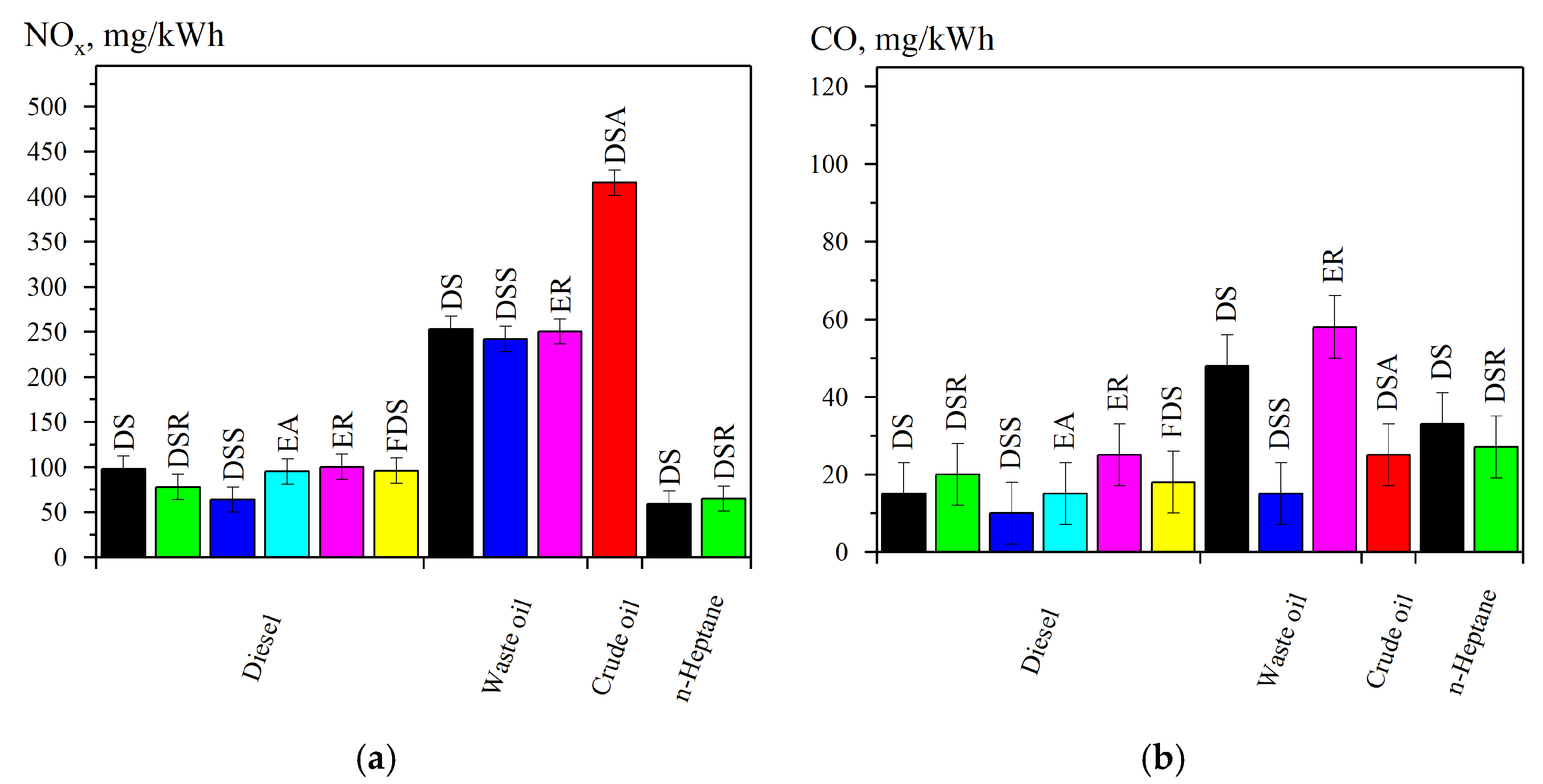
Based on the numerical simulation of the combustion process for liquid hydrocarbon fuels with partial gasification in the burner device, which involves fuel spraying using a steam jet and adjusting air supply parameters for the gas generation and combustion chambers, as well as comparing these results with previously obtained experimental data from atmospheric burners, the significant impact of steam has been demonstrated. Table 3 shows various types of liquid hydrocarbons, for which the developed schemes of interaction between superheated steam and fuel were tested. It also includes references to the results of work that has previously been carried out. This allowed us to identify parameters that can be used to control the emissions of toxic combustion products, such as NOx and CO, in these types of burners. The indicators for nitrogen oxide and carbon monoxide content in combustion products for each of the devices studied are presented in Figure 4.
It can be observed from this Figure that the combustion of fuel during partial steam gasification results in the best emission performance for all structures. The optimal values of control operating parameters (steam and air flow) ensure high combustion rates. Each design can be applied in various practical scenarios, which will influence the choice of steam feed and its interaction with the fuel.

4. Conclusions

Based on numerical simulation, this study has revealed that the decrease in the production of harmful combustion products can be attributed to the influence of superheated steam on the rate of chemical reactions involving the OH radical. A comparison of the results of comprehensive studies on the effect of superheated steam on the combustion characteristics of liquid hydrocarbon fuels and industrial waste using evaporative and spray burners in conditions of natural or controlled airflow is presented. Designs of burners and values of control operating parameters that provide high thermal and environmental performance have been substantiated. At the same time, the burners may be suitable for a variety of practical applications, and this will determine the selection of steam supply and its interaction with the fuel.
Obtained dependences on combustion parameters allow for the justification of recommendations for the efficient use of the method for burning liquid hydrocarbons using high-speed superheated steam jets, as follows:
(1)
To comply with the emissions of toxic combustion products from class 3 EN-267 burners up to 20 kW, relative steam consumption must exceed 0.6. At the same time, high combustion completeness is ensured, whereby this ratio does not exceed a certain value depending on the type of burner device—1.0 for an evaporation burner; 1.0 for a direct flow spray burner; and 1.2 for a swirl spray burner.
(2)
A temperature of superheated steam of 250 °C ensures stable operation over a wide range of conditions.
(3)
An additional reduction in the production of toxic products depends on the excess air ratio. A supply of air to the gas generation chamber ranging from 0.3 to 0.15 times stoichiometric leads to a decrease in NOx by up to 20% (too low an air intake does not ensure stable combustion).
The results obtained using burner devices of various types form the basis for further studies of the characteristics of ignition and combustion processes of different types of hydrocarbon fuel on large-scale firing stands over a wide range of operating conditions.

Author Contributions

Conceptualization, O.S.; methodology, A.M.; software and validation, V.K. and A.M.; formal analysis, O.S.; investigation, E.K.; writing—original draft preparation, E.K.; writing—review and editing, S.A. and O.S.; supervision, S.A. All authors have read and agreed to the published version of the manuscript.

Funding

This work was financially supported by the Ministry of Science and Higher Education of the Russian Federation, Agreement of 24.04.2024 No. 075-15-2024-543.

Data Availability Statement

The original contributions presented in the study are included in the article, further inquiries can be directed to the corresponding author.

Conflicts of Interest

The authors declare no conflicts of interest.

References

  1. De Giorgi, M.G.; Pescini, E.; Campilongo, S.; Ciccarella, G.; Fontanarosa, D.; Ficarella, A. Effects of emulsified fuel on the performance and emission characteristics of aeroengine combustors. J. Eng. Gas Turbines Power 2019, 141, 101021. [Google Scholar] [CrossRef]
  2. Xiaogang, W.; Bolan, L.; Xiyang, Y.; Chao, Y.; Fei, Y.; Zhenfeng, Z. Study on fuel and injection influence on a spark ignition aeropiston engine. J. Eng. Gas Turbines Power 2020, 142, 71006. [Google Scholar] [CrossRef]
  3. Aradhey, Y.; Stroud, Z.; Meadows, J. The Effect of Swirl Number On Lean Blow Out Limits of Lean Direct Injection Combustors. J. Eng. Gas Turbines Power 2024, 146, 101005-1. [Google Scholar] [CrossRef]
  4. Glassman, I.; Yetter, R.A. Combustion; Glassman, I., Yetter, R.A., Glumac, N.G., Eds.; Academic Press: Cambridge, MA, USA, 2008; ISBN 978-0-12-088573-2. [Google Scholar]
  5. Anufriev, I.S.S. Review of water/steam addition in liquid-fuel combustion systems for NOx reduction: Waste-to-energy trends. Renew. Sustain. Energy Rev. 2021, 138, 110665. [Google Scholar] [CrossRef]
  6. Makwana, J.; Dhass, A.D.; Ramana, P.V.; Sapariya, D.; Patel, D. An analysis of waste/biomass gasification producing hydrogen-rich syngas: A review. Int. J. Thermofluids 2023, 20, 100492. [Google Scholar] [CrossRef]
  7. Anitescu, G.; Bruno, T.J.; Tavlarides, L.L. Dieseline for Supercritical Injection and Combustion in Compression-Ignition Engines: Volatility, Phase Transitions, Spray/Jet Structure, and Thermal Stability. Energy Fuels 2012, 26, 6247–6258. [Google Scholar] [CrossRef]
  8. Su, C.-G.; Lin, S.-J. Burner of Liquid Fuel. Patent TW201116779A, 16 May 2011. [Google Scholar]
  9. Kuk, O.B. Liquid Fuel Burner. Patent KR20170052186A, 12 May 2017. [Google Scholar]
  10. Ritter, K.; Klausmann, W. Burner for Liquid Fuel. Patent DE102009043681A1, 7 April 2011. [Google Scholar]
  11. Pannwitz, T.; Schwanecke, M.; Smigiel, B. Burner for Burning Liquid Fuel. Patent DE102011006370A1, 4 October 2012. [Google Scholar]
  12. Li, Y. Liquid Fuel Burner. Patent CN101968218A, 9 February 2011. [Google Scholar]
  13. Lin, R.; Tavlarides, L.L. Thermal stability and decomposition of diesel fuel under subcritical and supercritical conditions. J. Supercrit. Fluids 2013, 75, 101–111. [Google Scholar] [CrossRef]
  14. Higman, C.; Van der Burgt, M. Gasification; Elsevier: Amsterdam, The Netherlands, 2008; ISBN 9780750685283. [Google Scholar] [CrossRef]
  15. Jin, X.; Teng, D.; Fang, J.; Liu, Y.; Jiang, Z.; Song, Y.; Zhang, T.; Siyal, A.A.; Dai, J.; Fu, J.; et al. Petroleum oil and products recovery from oily sludge: Characterization and analysis of pyrolysis products. Environ. Res. 2021, 202, 111675. [Google Scholar] [CrossRef]
  16. Castillo Santiago, Y.; Pérez, J.F.; Sphaier, L.A. Reaction-front and char characterization from a palm kernel shell—Oil sludge mixture under oxygen lean regimes in a fixed-bed gasifier. Fuel 2023, 333, 126402. [Google Scholar] [CrossRef]
  17. Ahmadi, M.A.; Masoumi, M.; Askarinezhad, R. Evolving Connectionist Model to Monitor the Efficiency of an In Situ Combustion Process: Application to Heavy Oil Recovery. Energy Technol. 2014, 2, 811–818. [Google Scholar] [CrossRef]
  18. Cheng, S.; Wang, Y.; Fumitake, T.; Kouji, T.; Li, A.; Kunio, Y. Effect of steam and oil sludge ash additive on the products of oil sludge pyrolysis. Appl. Energy 2017, 185, 146–157. [Google Scholar] [CrossRef]
  19. Chu, Z.; Li, Y.; Zhang, C.; Fang, Y.; Zhao, J. A review on resource utilization of oil sludge based on pyrolysis and gasification. J. Environ. Chem. Eng. 2023, 11, 109692. [Google Scholar] [CrossRef]
  20. Yan, B.; Jia, X.; Li, J.; Li, Z.; Che, Y.; Zhou, Z.; Zhao, J.; Zhou, S.; Chen, G. In-situ elimination of biomass gasification tar based on the understanding of tar formation process: A review. J. Energy Inst. 2024, 112, 101477. [Google Scholar] [CrossRef]
  21. Mendiara, T.; Adánez-Rubio, I.; Gayán, P.; Abad, A.; de Diego, L.F.; García-Labiano, F.; Adánez, J. Process Comparison for Biomass Combustion: In Situ Gasification-Chemical Looping Combustion (iG-CLC) versus Chemical Looping with Oxygen Uncoupling (CLOU). Energy Technol. 2016, 4, 1130–1136. [Google Scholar] [CrossRef]
  22. Shen, Y. Biomass pretreatment for steam gasification toward H2-rich syngas production—An overview. Int. J. Hydrogen Energy 2024, 66, 90–102. [Google Scholar] [CrossRef]
  23. Xu, M.; Wu, Y.; Nan, D.; Lu, Q.; Yang, Y. Effects of gaseous agents on the evolution of char physical and chemical structures during biomass gasification. Bioresour. Technol. 2019, 292, 121994. [Google Scholar] [CrossRef] [PubMed]
  24. Cao, L.; Yu, I.K.M.; Xiong, X.; Tsang, D.C.W.; Zhang, S.; Clark, J.H.; Hu, C.; Ng, Y.H.; Shang, J.; Ok, Y.S. Biorenewable hydrogen production through biomass gasification: A review and future prospects. Environ. Res. 2020, 186, 109547. [Google Scholar] [CrossRef]
  25. Piazzi, S.; Menin, L.; Antolini, D.; Patuzzi, F.; Baratieri, M. Potential to retrofit existing small-scale gasifiers through steam gasification of biomass residues for hydrogen and biofuels production. Int. J. Hydrogen Energy 2021, 46, 8972–8985. [Google Scholar] [CrossRef]
  26. Alekseenko, S.V.; Pashchenko, S.É.; Salomatov, V.V. Nanocluster initiation of combustion of off-grade hydrocarbon fuels. J. Eng. Phys. Thermophys. 2010, 83, 729–741. [Google Scholar] [CrossRef]
  27. Jang, H.H.; Hwa, S.S. Combustion Burner Apparatus Using Superheated Steam. Patent KR102018297B1, 5 September 2019. [Google Scholar]
  28. Jian, L.; Deyong, W.; Dong, W. Heavy Component Reinforced Torch Burner. Patent CN214370256U, 8 October 2021. [Google Scholar]
  29. Fuxiang, G.; Jun, C.; Jian, H. Burner for Incineration. Patent CN105605573A, 25 May 2016. [Google Scholar]
  30. Jian, L.; Deyong, W.; Dong, W. Low-Calorific-Value Heavy Component Combined Torch Burner. Patent CN214275702U, 24 September 2021. [Google Scholar]
  31. Ott, J.; Gronemann, V.; Lehmann, M.; Krimlowski, P.M. Burner and Process for Producing Synthesis Gas. Patent US20200180954A1, 11 June 2020. [Google Scholar]
  32. Alekseenko, S.V.; Anufriev, I.S.; Vigriyanov, M.S.; Kopyev, E.P.; Sharypov, O.V. Characteristics of diesel fuel combustion in a burner with injection of a superheated steam jet. Combust. Explos. Shock Waves 2016, 52, 286–293. [Google Scholar] [CrossRef]
  33. Anufriev, I.S.; Alekseenko, S.V.; Sharypov, O.V.; Kopyev, E.P. Diesel fuel combustion in a direct-flow evaporative burner with superheated steam supply. Fuel 2019, 254, 115723. [Google Scholar] [CrossRef]
  34. Anufriev, I.S.; Kopyev, E.P.; Mukhina, M.A.; Sadkin, I.S. Investigation into Characteristics of Combustion of n-Heptane Sprayed by Jet of Steam or Air. J. Eng. Thermophys. 2022, 31, 420–428. [Google Scholar] [CrossRef]
  35. Anufriev, I.S.; Kopyev, E.P.; Sadkin, I.S.; Mukhina, M.A. Diesel and waste oil combustion in a new steam burner with low NOX emission. Fuel 2021, 290, 120100. [Google Scholar] [CrossRef]
  36. Anufriev, I.S.; Alekseenko, S.V.; Kopyev, E.P.; Sharypov, O.V. Combustion of Substandard Liquid Hydrocarbons in Atmosphere Burners with Steam Gasification. J. Eng. Thermophys. 2019, 28, 324–331. [Google Scholar] [CrossRef]
  37. Anufriev, I.S.; Kopyev, E.P.; Sadkin, I.S.; Mukhina, M.A.; Minakov, A.V.; Kuznetsov, V.A. Combustion of n-heptane with steam injection in a laboratory spray burner. Thermophys. Aeromech. 2023, 30, 249–262. [Google Scholar] [CrossRef]
  38. Sadkin, I.S.; Mukhina, M.A.; Shadrin, E.Y.; Kopyev, E.P. Design, Adjustment, and Mode Research of Low-Emission Burner for Fuel Combustion in a Superheated Steam Jet. J. Appl. Mech. Tech. Phys. 2024, 65, 1–6. [Google Scholar] [CrossRef]
  39. DIN EN 267:2011-11; Automatic Forced Draught Burners for Liquid Fuels. Beuth Verlag GmbH: Berlin, Germany, 2011.
  40. Minakov, A.V.; Anufriev, I.S.; Kuznetsov, V.A.; Dekterev, A.A.; Kopyev, E.P.; Sharypov, O.V. Combustion of liquid hydrocarbon fuel in an evaporative burner with forced supply of superheated steam and air to the reaction zone. Fuel 2022, 309, 122181. [Google Scholar] [CrossRef]
  41. Anufriev, I.S.; Shadrin, E.Y.; Kopyev, E.P.; Sharypov, O.V. Experimental investigation of size of fuel droplets formed by steam jet impact. Fuel 2021, 303, 121183. [Google Scholar] [CrossRef]
  42. Alekseenko, S.V.; Anufriev, I.S.; Arsentyev, S.S.; Vigriyanov, M.S.; Kopyev, E.P.; Sharypov, O.V. Influence of parameters of superheated steam on combustion of liquid hydrocarbons. Thermophys. Aeromech. 2019, 26, 103–107. [Google Scholar] [CrossRef]
  43. Mulhem, B.; Fritsching, U.; Schulte, G.; Bauckhage, K. Effect of solid particle characteristics on suspension atomization. At. Sprays 2003, 13, 321–343. [Google Scholar] [CrossRef]
  44. Ashgriz, N. Handbook of Atomization and Sprays; Springer: New York, NY, USA, 2011. [Google Scholar] [CrossRef]
  45. Azzopardi, B.J. Drop sizes in annular two-phase flow. Exp. Fluids 1985, 3, 53–59. [Google Scholar] [CrossRef]
  46. Hede, P.D.; Bach, P.; Jensen, A.D. Two-fluid spray atomisation and pneumatic nozzles for fluid bed coating/agglomeration purposes: A review. Chem. Eng. Sci. 2008, 63, 3821–3842. [Google Scholar] [CrossRef]
  47. Danis, A.M.; Namer, I.; Cernansky, N.P. Droplet size and equivalence ratio effects on spark ignition of monodisperse N-heptane and methanol sprays. Combust. Flame 1988, 74, 285–294. [Google Scholar] [CrossRef]
  48. Odgers, J.; Kretschmer, D.; Pearce, G.F. The Combustion of Droplets Within Gas Turbine Combustors: Some Recent Observations on Combustion Efficiency. J. Eng. Gas Turbines Power 1993, 115, 522–532. [Google Scholar] [CrossRef]
  49. Kramm, K.; Orth, M.; Teiwes, A.; Kammerhofer, J.C.; Meunier, V.; Pietsch-Braune, S.; Heinrich, S. Influence of Nozzle Parameters on Spray Pattern and Droplet Characteristics for a Two-Fluid Nozzle. Chem. Ing. Tech. 2023, 95, 151–159. [Google Scholar] [CrossRef]
  50. Razak, A.M.Y. Industrial Gas Turbines: Performance and Operability; Woodhead Publishing Limited: Sawston, UK, 2007; ISBN 9781845692056. [Google Scholar] [CrossRef]
  51. Anufriev, I.; Kovyev, E.; Alekseenko, S.S.; Sharypov, O.; Butakov, E.; Vigriyanov, M.; Sadkin, I. Cleaner crude oil combustion during superheated steam atomization. Therm. Sci. 2021, 25, 331–345. [Google Scholar] [CrossRef]
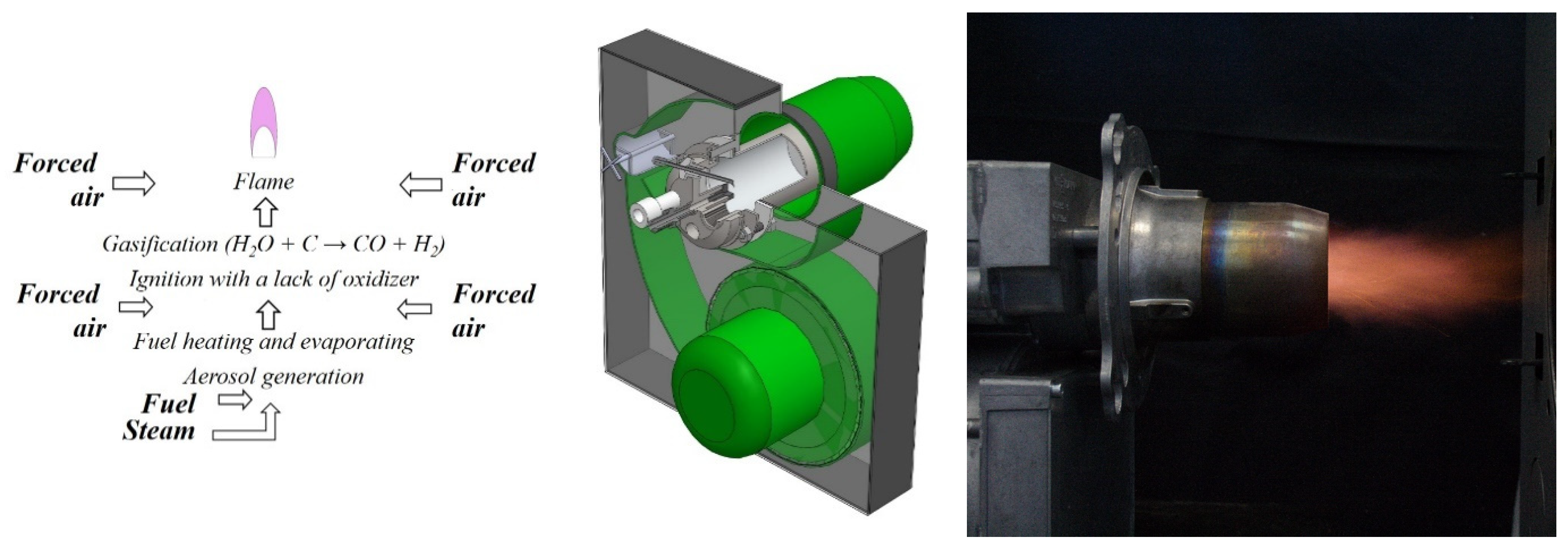
Figure 1. Diagram and photo of FDS with steam injection for liquid fuels.
Energies 17 05047 g001
Figure 2. Central cross-section of the design area along the axis of the device (a); the design grid in the volume of the boiler and burner device (b).
Energies 17 05047 g002
Figure 3. Distribution of temperature and flame components (CO, NOx, and OH) in the central cross-section at a relative steam consumption of 0.02, 0.3, and 0.5 (from left to right).
Energies 17 05047 g003aEnergies 17 05047 g003b
Figure 4. Indicators of (a) nitrogen oxides and (b) carbon monoxide in combustion products for FDS and atmospheric burner devices (Section 3.2, according to Table 2).
Energies 17 05047 g004
Table 1. Integral values for CO and NOx at the exit of the combustion chamber.
Numerical SimulationExperiment [38]
Relative steam consumption0.020.30.51.01.4
Temperature, °C493446436--
CO, ppm (mg/kWh)20,000 (28,900)23 (33)16 (22)35 (53)24 (35)
NOx, ppm (mg/kWh)145 (344)61 (147)58 (135)57 (138)52 (127)
Table 2. Design of burner devices.
NameSchemeGraphic ModelFlame Photo
Evaporative burner with Autonomous steam generation (EA)Energies 17 05047 i001Energies 17 05047 i002Energies 17 05047 i003
Evaporative burner with Regulated steam supply (ER)Energies 17 05047 i004Energies 17 05047 i005
Direct-flow Spray burner (DS)Energies 17 05047 i006Energies 17 05047 i007Energies 17 05047 i008
Direct-flow spray burner with Afterburner (DSA)Energies 17 05047 i009Energies 17 05047 i010Energies 17 05047 i011
Direct-flow Swirl Spray burner (DSS)Energies 17 05047 i012Energies 17 05047 i013Energies 17 05047 i014
Direct-flow Spray burner with Regulated air supply to the gas generation chamber (DSR)Energies 17 05047 i015Energies 17 05047 i016Energies 17 05047 i017
Table 3. Research of various fuel type combustion in the developed burner devices.
BurnerRef.Fuel Type
DieselWaste OilCrude Oiln-Heptane
FDS[38]
EA[32]
ER[33]
[42]
[40]
DS[34]
[36]
DSA[51]
DSS[35]
DSR[37]
Disclaimer/Publisher’s Note: The statements, opinions and data contained in all publications are solely those of the individual author(s) and contributor(s) and not of MDPI and/or the editor(s). MDPI and/or the editor(s) disclaim responsibility for any injury to people or property resulting from any ideas, methods, instructions or products referred to in the content.