1. Introduction
In the UK, space heating and hot water provision for buildings contribute to more than 40% of the energy consumption [
1,
2]. However, heating for buildings still predominantly relies on fossil fuels, with renewable energy sources playing a minimal role. This inevitably leads to substantial CO
2 emissions. Therefore, increasing the penetration of renewable heat technologies in the building sector is key to the UK meeting its carbon emission reduction targets.
Solar energy is a prominent renewable resource as it is infinite, easily available, and non-polluting. However, in the UK, there is only 1% of renewable heat from solar currently exploited. In addition to the reason that the UK is located in a high-latitude region with relatively weak solar radiation, another important reason lies in the seasonal mismatch between heating demand and solar thermal energy availability. In summer, solar energy can produce abundant thermal and electrical power that sometimes substantially exceeds the actual heat and electricity demands of households. However, most of the heating demands occur in winter time. The use of seasonal solar energy storage (SSES) can effectively compensate for this seasonal mismatch [
3]. It can store abundant but relatively low-temperature solar heat in summer and utilise this at the desired temperature for space and hot water heating in winter [
4,
5]. In the field of solar energy utilisation, advancements in thermal energy storage (TES) have been central to addressing the challenges of energy storage efficiency and system reliability [
6], especially in the context of seasonal variations in solar availability. Key developments have been made in enhancing the performance of TES systems, with a particular focus on the improved design and material utilisation of these systems. This includes exploring the dynamics of phase change materials (PCMs) and their interaction with external factors, like electric fields, to optimise the melting process within TES units [
7]. Such innovations have proven pivotal in augmenting the efficiency of solar energy storage. These advanced TES technologies are particularly suitable for regions with fluctuating solar intensity, offering promising solutions for more consistent and effective utilisation of solar power.
When discharging the stored solar heat, a seasonal solar energy storage system usually requires a heat pump to upgrade the temperature to a useful level, for domestic hot water (DHW) or space heating provision [
8]. Many studies focusing on the integration of a seasonal solar energy storage tank with heat pumps for domestic application have been conducted. Yumrutas et al. [
9] modelled a spherical SSES tank coupled with a vapour compression heat pump to provide space heating for a single-family house (with 100 m
2 floor area) in Gaziantep, Turkey. The heat pump uses the heat in the tank as a heat source, and they found such a system can reach an annually periodic situation in 5–7 years. Hesaraki et al. [
10] studied the influence of heat emission design temperature on the performance of a solar system that integrates a stratified SSES tank with a vapour compression heat pump in series, and their analysis shows that a lower heat emission design temperature is beneficial for the system efficiency’s improvement. Pinamonti et al. [
11] evaluated the integration of a water-to-water heat pump in an SSES system for SH and DHW production of a single-family house in Ottawa, Canada, and they compared the proposed system’s performance with a similar system but without a heat pump. The results show that the addition of a heat pump will increase the solar fraction level and the seasonal tank’s storage efficiency, but the tank size and the solar collector areas should be carefully chosen to maximise the benefit of the HP integration. Martínez-Gracia et al. [
12] proposed a hybrid photovoltaic–thermal collector-assisted heat pump with seasonal storage for a social building in Zaragoza, Spain. With hourly demands obtained in DesignBuilder as inputs, they performed annual simulations for the whole energy system in TRNSYS 18 software.
The results show that such a system has a payback period of 8.5 years and meanwhile offering great environmental benefits. Del Amo et al. [
13] from the same group also optimised a similar system but applied it to an educational building in a middle latitude. The results show that such a system brings considerable economic savings due to the use of a renewable energy sources.
The heat pumps employed in the above research are all conventional vapour compression heat pumps. Compared with conventional vapour compression heat pumps, thermoelectric heat pumps have a lower coefficient of performance (COP) under the same working conditions [
14], but they have the advantages of silent operation, are environmentally friendly, have high reliability (due to the absence of moving parts), and can be powered by PV cells directly. With the promotion of Nearly Zero-Energy Buildings (NZEBs) [
15,
16], the number of buildings with low heating and cooling loads will increase accordingly. In this context, thermoelectric heat pumps may find important applications in the building sector by virtue of their advantages over conventional vapour compression heat pumps. Therefore, growing research has focused on the application of thermoelectric heat pumps in the building sector. Aranguren et al. [
17] studied using a thermoelectric cooler-heat pump with heat pipes to cover the HVAC demand for NZEBs, with an emphasis on thermal characterisation of the heat pipes. They found that the thermoelectric module number, air mass flow, and the position of the device should be carefully chosen to achieve optimal operation of the device. Xu et al. carried out a study for residential buildings exploring a passive technology solution combining TE heat pumps and heat pipe heat recovery technology. This integrated system was introduced with the aim of reducing energy consumption for space heating and, at the same time, meeting the necessary ventilation requirements. The solution offers a number of advantages such as energy efficiency, environmental friendliness, and compactness, while also allowing for modular production when integrated with window frames [
18]. In a numerical analysis performed by Allouhi et al., they evaluated the use of a thermoelectric heating system in a Moroccan office room and concluded that this system could reduce the office room’s energy consumption by up to 64% compared to conventional electric heaters [
19].
Given the advantage of thermoelectric heat pumps, integrating an SSES tank with a thermoelectric heat pump appears to present a particularly suitable solution for domestic applications. However, to the best of our knowledge, few studies have considered such a solution. Our group aims to fill this gap, and to do so, two important issues must be solved.
Firstly, to evaluate the technical and economic feasibility of such a solution in different load environments, an accurate and practical simulation model of thermoelectric heat pumps is indispensable. Many researchers have developed numerical models for thermoelectric heat pumps or thermoelectric air-conditioning systems [
20,
21]. These models focus on characterising the thermophysical processes occurring within the heat pumps and are useful for improving the designs of heat pumps by analysing the major energy losses and optimising geometries of both the thermoelectric modules and the heat exchangers located at the two sides of the thermoelectric modules. However, they are not suitable for building energy simulation due to the mismatch of the time scales (the time scales used in building simulation are 100–103 s [
22], which are much larger than the time scales of these models). Though limited numerical models addressed to building energy simulation tools had been developed [
19,
23], most of these models are not validated by experiments; hence, they cannot accurately provide meaningful system-level results when performing techno-economic analysis. As such, developing a numerical model for thermoelectric heat pumps suitable for building energy simulation and validating it via experiments is one of the goals of this work.
Secondly, the benefits achievable for a thermoelectric heat pump, thanks to the integration with heat storage, should be identified both numerically and experimentally. Though numerous research for a standalone thermoelectric heat pump or air-conditioning have been performed both numerically and experimentally [
24,
25], few studies focus on the integration between a thermoelectric heat pump with heat storage, which leaves the benefits achievable for a thermoelectric heat pump thanks to the integration with heat storage as still unclear. Therefore, identifying the benefits achievable for a thermoelectric heat pump thanks to the integration with heat storage and clarifying the potential of this kind of integration is the other goal of this work.
With these two goals in mind, in this work, we developed an experimental apparatus which integrates a TEHP unit with a heat storage tank (HST) for the first time, and the TEHP unit was tested under two different scenarios, i.e., with heat storage and without heat storage, to characterise the performance of the TEHP unit comprehensively. In addition, a numerical model which can describe the whole system is developed in TRNSYS. The model includes a sub-model of the TEHP unit being implemented in Matlab, enabling for it to be used for building energy simulation. The accuracy of the model is validated against the experimental results to pave the way for following building-integrated simulations. In the following sections, we first introduce the experimental apparatus and the related measurements. Then, the modelling approach for the whole system, with an emphasis on the thermoelectric heat pump modelling, is described. Later, the effect of heat storage on the operation and performance of the TEHP unit are investigated numerically and experimentally. Finally, key conclusions are drawn from the results.
2. Experimental Methods
2.1. Apparatus Description
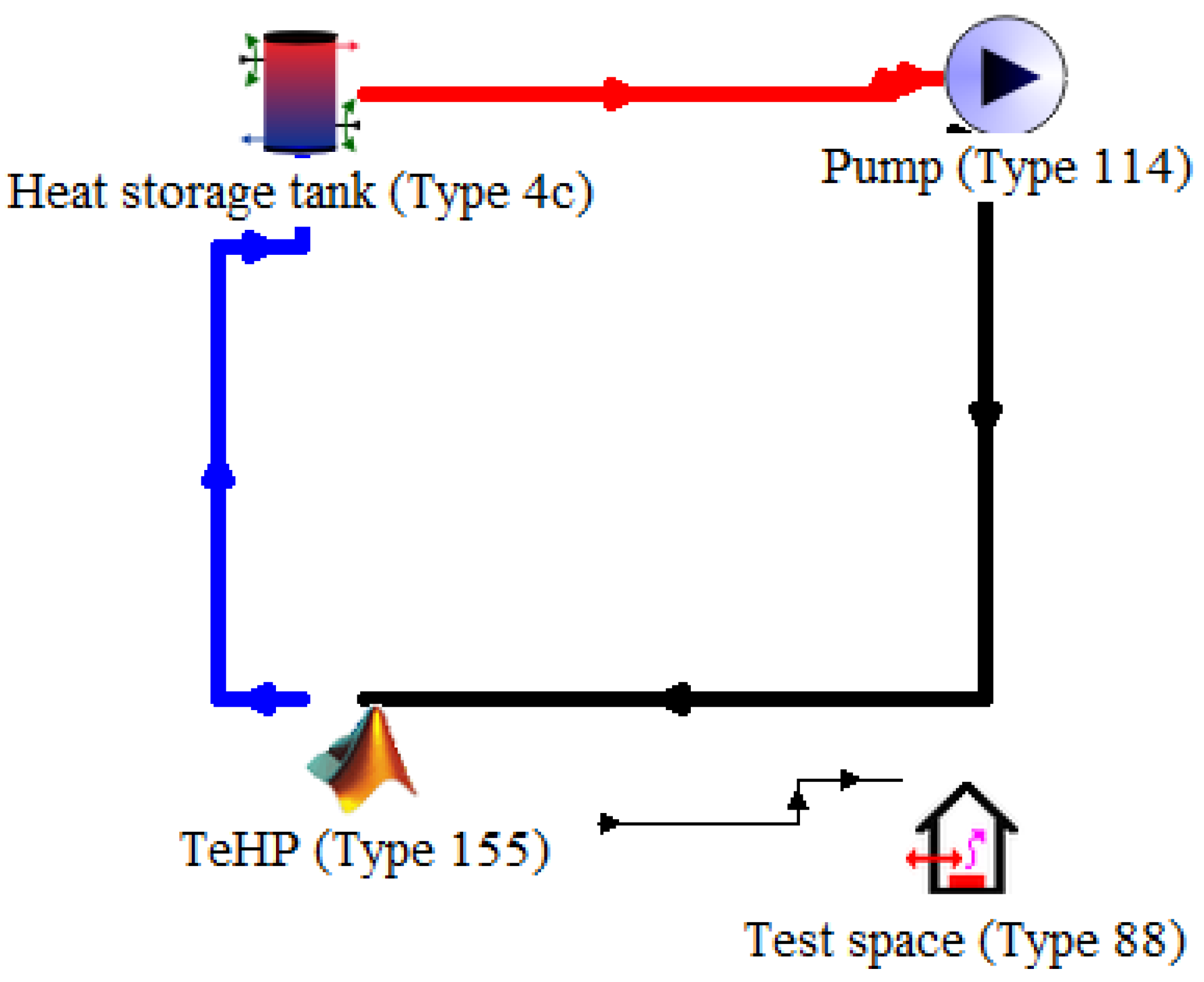
Figure 1a shows a schematic diagram of the built experimental apparatus, which integrates a TeHP unit with a heat storage tank (HST), and
Figure 1b shows a photograph of the experimental apparatus. The apparatus mainly includes a TeHP unit (shown in
Figure 1c), a heat storage tank, a testing box, and a data logger system.
The TeHP unit consists of one thermoelectric module (TeM), an aluminium-finned heat sink at the hot side of the TeM, and a water-cooled plate at the cold side of the TeM. The model of the employed TeM is TEC1-12706, whose technical specifications are presented in
Table 1. The examined attributes of the TEC1-12706 module are as follows: it has 127 thermocouples, designated as
N. The Seebeck coefficients for both n-type and p-type semiconductors have been assumed as constant, each with a value of
. The internal resistance
of each module is
, while the total thermal conductivity (
) registers at
. The figure of merit
is documented as
. Further details about these parameters can be found in [
25].
The TeM, which is powered by the DC power supply, is used. It should be noted that in domestic applications, the total heating capacity of the TEHP unit can be augmented by simply increasing the total number of the TeM. The aluminium-finned heat sink with a dimension of 200 mm in length, 182 mm in width, and 45 mm in height, consists of 19 fins with different fin thicknesses. To enhance the heat transfer between the TeM and the heat sink as well as the heat transfer between the TeM and the water-cooled plate, a high thermal conductance paste was placed at the two sides of the TeM to reduce the contact thermal resistances. In addition, a cross-flow fan was installed at the heat sink side to enhance the heat exchange between the airflow and the heat sink.
The heat storage tank, made of stainless steel, features an inner diameter of , a height of , and a thickness of . In the experiments, both the employed heat transfer fluid and the heat storage medium are water. To simulate the heat generated from the hybrid photovoltaicthermal (PVT) collectors or the solar thermal collectors in real application, three positive temperature coefficient (PTC) heaters are used to heat the water in the tank. The heat storage tank connects with the water-cooled plate via a pumped water circulation loop.
The TeHP unit was installed inside the testing box located in a lab room. The dimension of the testing box is
, with a volume of
. It was made of wooden panels with a thickness of
. The use of a testing box in this work is based on its effectiveness in replicating the thermal characteristics of a real building environment. This approach is commonly used to provide a similar and controlled indoor environment to real buildings for evaluating the performance of thermal energy systems [
25]. The use of a testing box facilitates more precise control of environmental factors and a better understanding of how the considered thermal energy systems perform in real building environments. The effectiveness of this approach has been validated in many studies [
26,
27]. In this work, the testing box is designed to simulate a typical building environment, allowing for accurate evaluation of TeHP devices under different conditions.
2.2. Measurements
As shown in
Figure 1a, to monitor the temperature inside the testing box, three platinum resistance temperature detectors (model: PT00, with an accuracy of
) were deployed at the top, middle, and bottom of the testing box (denoted by T3, T4, and T5 in
Figure 1a). In addition, another two platinum resistance temperature detectors with the same model were used to measure the inlet airflow temperature and outlet airflow temperature at the heat sink side (T1 and T2 in
Figure 1a). The hot- and cold-side temperatures of the TeMs are important for characterising the performance of the TeMs, which were monitored by another two platinum resistance temperature detectors (T6 and T7 in
Figure 1a). In addition, the ambient temperature is also measured in the experiments (T8 in
Figure 1a). The data logger collects all temperature signals simultaneously at 5 min intervals. Each test lasted 20 min and was repeated at least five times for each test condition to ensure the reliability of the test results. This repetition was essential to confirm the consistency and accuracy of the data. In addition, preliminary tests were conducted to determine the optimal duration of each experiment. These preliminary tests indicated that a 20 min test period was sufficient to allow the system to reach a steady state under a variety of conditions; therefore, 20 min was selected as the standard test duration for this study.
The experimental apparatus has been specifically constructed to incorporate the TEC1-12706 module as a thermoelectric heat pump (TeHP) for using the stored heat from a heat storage tank. Consequently, measurements of temperature fluctuations on the two sides of the TeHP and variations in input electric power—encompassing both voltage and current, as well as the heating power output from the TeHP—are performed. These parameters form the basis for calculating the COP of the TeHP under varying operational and environmental conditions, including temperature. This data subsequently informs the analysis and comparison of the overall system’s performance.
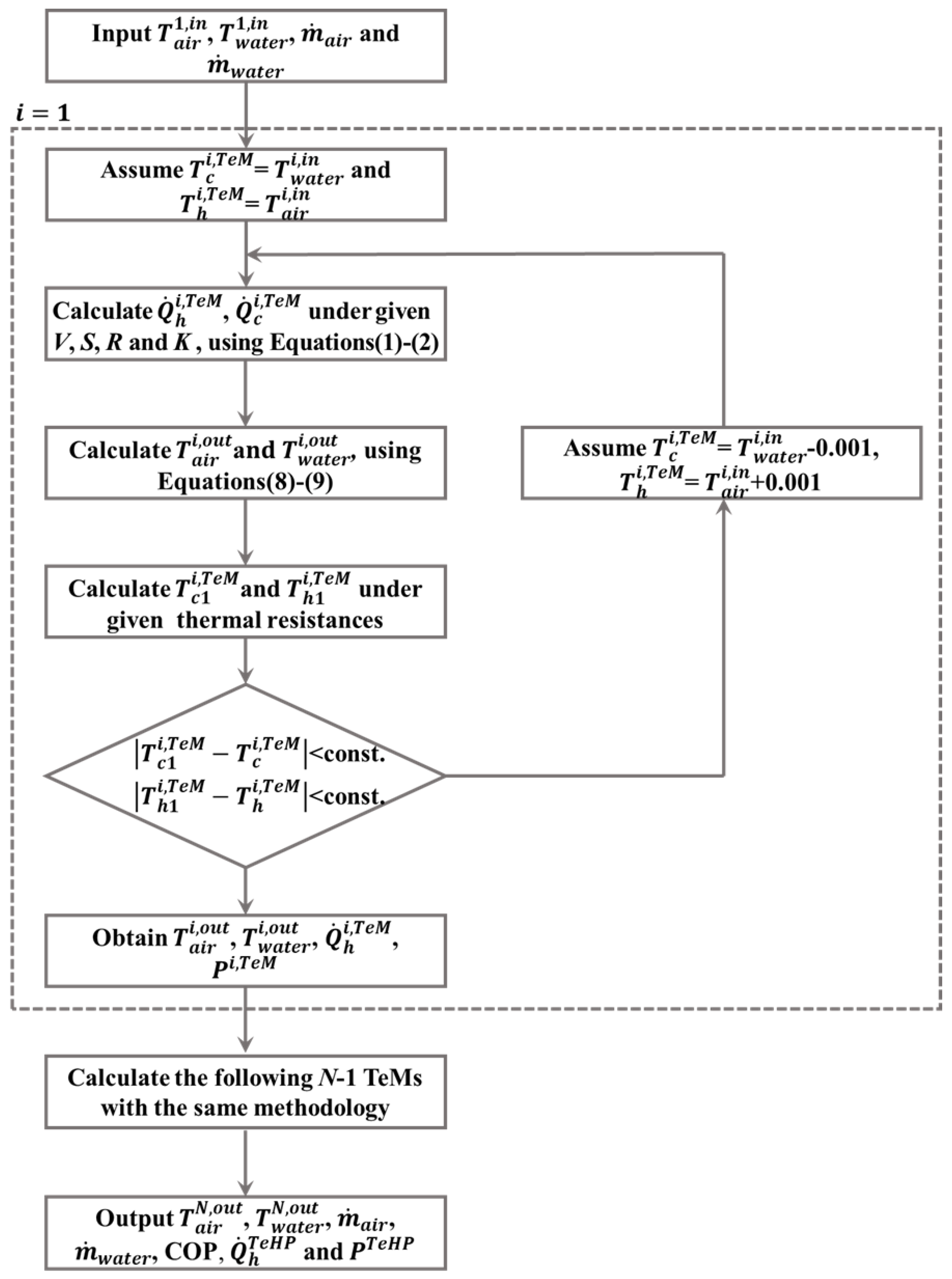
For each test, the test duration is 20 min. The TE module’s power consumption, heat production, and heating COP can be calculated using Equations (1), (2), and (3), respectively:
where
W is the power consumption (W);
is the heat generation by the TeHP,
N is the number of thermocouples in each TE module;
is the Seebeck coefficient, determined by the properties of the conductor material;
is the hot-side temperature (
C);
is the temperature difference between the hot and cold sides of the TE module (
C);
I is the instantaneous current consumption of the TE module (A);
R is the internal resistance of the TE module
; and
is the total thermal conductivity
.
The parameters measured during the experiment include temperature, current, voltage, and electrical power. The experiment reads a set of data every 5 min. The absolute measurement uncertainties of temperature, current, voltage, and electrical power are 1.4 C, 0.03 A, 0.02 V, and 0.07 W, respectively. The absolute uncertainty values for heating power and COP are 0.79 W and 0.025, respectively.
4. Results and Discussion
In this work, we systematically explore the output performance of the TeHP unit under a series of controlled tests (Test 0 to Test 6). These tests are categorised into two different scenarios, i.e., without heat storage scenario (Tests 0 and 1) and with heat storage scenario (Test 2 to Test 6). Each test was conducted for 20 min to measure the temperature variation trends inside the testing box, and the power consumption, heating power, and COP of the TeHP unit.
The system without heat storage:
Test 0: Establishes the control scenario with no water heating or water pumping, setting a reference test for comparison with other tests.
Test 1: Involves circulating water at an ambient temperature of 26.5 C, assessing the TeHP system’s performance without external heating from the PTC heaters but with water pumping.
The system with heat storage:
Tests 2 to 5: Water in the storage tank is continuously heated with the PTC heaters to maintain a constant temperature, and the system is tested with water pumping at different constant temperatures, including 30 C (Test 2), 35 C (Test 3), 40 C (Test 4), and 45 C (Test 5), to evaluate the TeHP unit’s response to controlled heating.
Test 6: The water in the storage tank is first heated to 45 C, and then the PTC heaters are switched off in order to track the system’s performance variation under the condition that no further external heating once heat is stored.
4.1. The System without Heat Storage
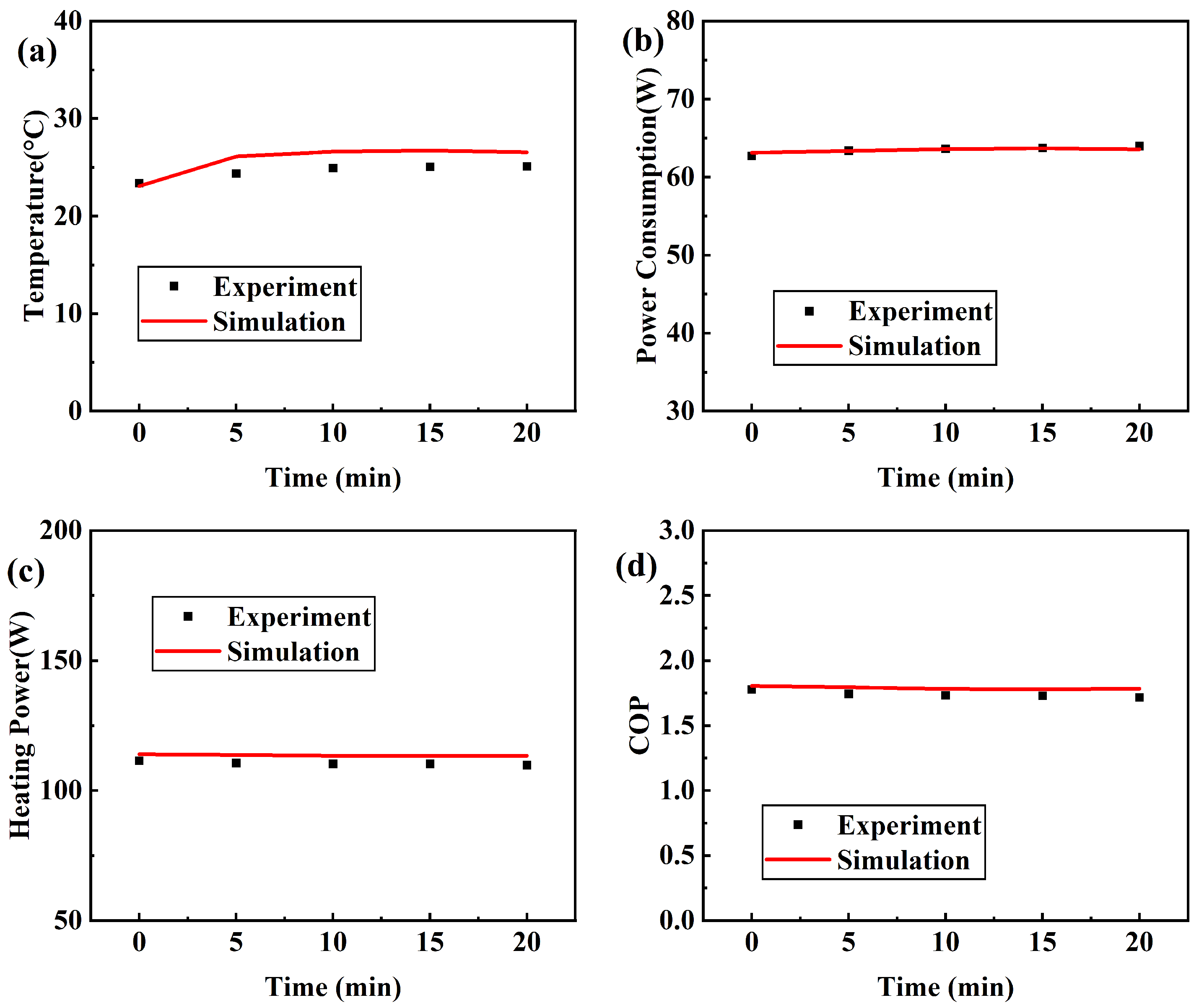
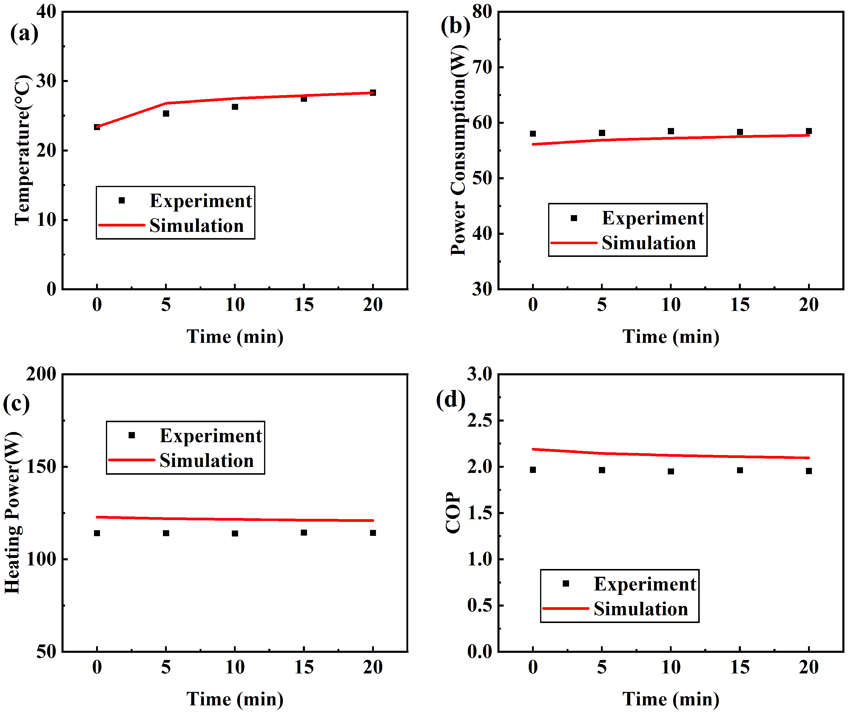
Figure 4 presents a comparison of simulation and experimental results for Test 0, where the system operates without external heating or water pumping, running solely on the thermoelectric (TE) module. This scenario serves as a baseline for the performance of the TeHP unit in the absence of a heat storage tank and a water circulation loop. The figures are labelled from (a) to (d), with each figure representing a different aspect of the system’s performance over a period of 20 min.
Figure 4a shows the temperature variation inside the testing box. Both the experimental and numerical data show a relatively flat line, indicating a slow rise in temperature inside the box due to the absence of heating and pumping activity. In
Figure 4b, the power consumption of the TeHP unit almost remains constant over time.
Figure 4c shows the heating power variation, which remains at the baseline level in both the experimental and simulation data. Lastly,
Figure 4d presents the COP of the TeHP unit over time. Overall, the good consistency between the simulated and experimental results in Test 0 validates the simulation model under the specific conditions of no active heating or water pumping, providing a baseline for understanding the TeHP unit’s behaviour in isolation.
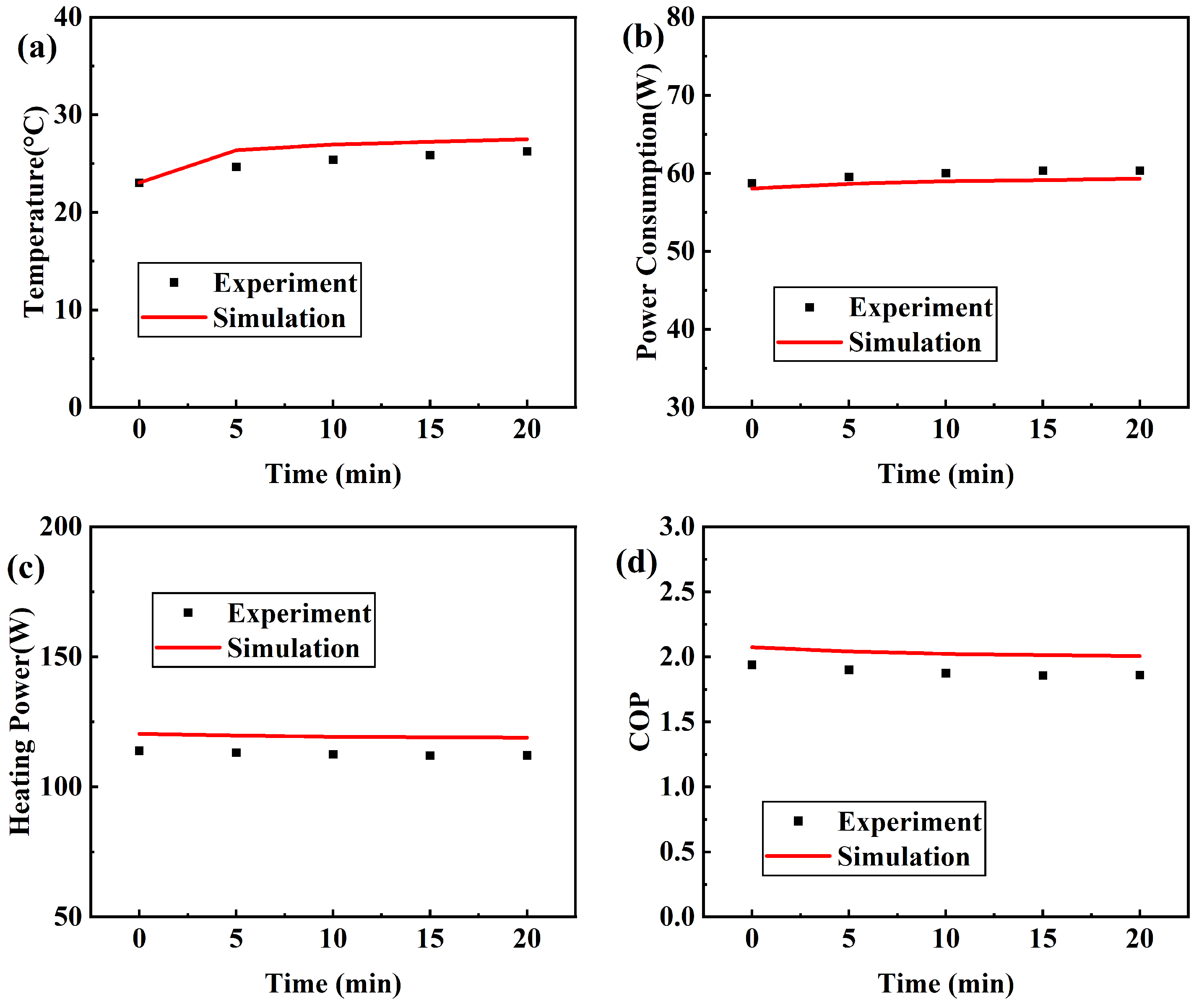
Figure 5 displays the results from Test 1, which features a water circulation loop in operation but maintains the water in the heat storage tank at a constant ambient temperature of 26.5
C. The TeHP unit settings remain unchanged throughout this test.
Figure 5a shows the temperature variation within the box over time. The experimental results, denoted by square markers, and the simulation, represented by the solid line, both exhibit a slight increase before reaching stable values.
Figure 5b reveals the change in the TeHP unit’s power consumption over the 20 min period. One can see that the power consumption of the TeHP unit is steady, as reflected by both the experimental and simulated data.
Figure 5c focuses on the heating power of the TeHP unit, which remains relatively flat over time. Compared with
Figure 4c (with an average heating power of 107 W), there is a slight increase (by 3%) in the TeHP unit’s heating power after using circulating water at ambient temperature as a heat source. This indicates that, despite the operation of the water circulation loop, the use of circulating water with ambient temperature does not contribute to a significant increase in the TeHP unit’s heating power. Lastly,
Figure 5d illustrates the COP over time. With the water at ambient temperature and the pump in operation, the COP values shown are close to what would be expected for a system without active heating. Both the experimental and simulation trends of COP are in close agreement and remain fairly constant. Overall, Test 1 provides insights into the system’s behaviour with an active pump but without external heating, serving as an intermediary step between the baseline condition (no water pump, no external heating) and fully operational (with water pump in operation and heated circulating water) conditions.
4.2. The System with Heat Storage
After evaluating the operation and performance of the TeHP unit under the condition that without heat storage, to identify the benefits achievable for a TeHP thanks to the integration with heat storage, in this section, we further evaluate the operation and performance of the TeHP unit with heat storage numerically and experimentally.
Figure 6 presents a comparison of the simulation and experimental results for Test 2 under specific conditions. The experimental setup includes the water pump, which operates normally; the heat storage tank, which maintains a consistent temperature of 30
C; and the TeHP unit, which operates at a voltage of 11.78 V and a current of 5.30 A over a duration of 20 min.
Figure 6a illustrates the temperature variation inside the testing box over time. In the experiments, the temperature inside the testing box increases from 23.6 to 27.0
C. Both simulated and experimental trends agree well with each other, with temperatures rising gradually and eventually stabilising.
Figure 6b describes the change in power consumption over time. Here, the simulated data aligns well with the experimental findings.
Figure 6c compares the numerical and experimental results in heating power variation. One can see that the simulated results are slightly higher than the experimental data, with the difference being less than 5%. This deviation may stem from experimental measurement errors and the inherent simplifications of the numerical model.
Figure 6d gives the relationship between COP and time. Similar to heating power, the simulated data of COP slightly exceeds the experimental data, with the deviation remaining below 5%.
Figure 7 showcases the comparison for Test 3 under specific conditions. The conditions for this test are the water pump operates reliably, the heat storage tank maintains a temperature of 35
C, and the TeHP unit runs at a voltage of 11.77 V and a current of 5.30 A. The observations and analyses for the subfigures in
Figure 4 align with those of Test 2. However, it is worth noting that in
Figure 7a, the simulated temperatures inside the testing box marginally surpass the experimental temperatures as time goes by, while the deviation remains below 6% during the test.
The specific experimental conditions and primary observations for
Figure 8 (corresponding to Test 4, with a steady water temperature of 40
C in the heat storage tank) and
Figure 9 (corresponding to Test 5, with a steady water temperature of 45
C) are similar to the aforementioned tests.
Figure 10 shows a comparison of simulated and experimental results for Test 6. The experimental setup consisted of the water pump running normally, where the initial water temperature in the heat storage tank was 45
C and the water was cooled naturally to 41.3
C at the end of the test, without external heating from the PTC heaters. The TeHP unit ran for 20 min with a voltage supply of 11.63 V and a current supply of 5.24 A.
Figure 10a details the temperature profile inside the testing box under the condition of non-continuous heating of the heat storage tank’s water. In the experiments, the temperature inside the testing box goes up from 22.4 to 27.8
C. The simulated and experimental trends are very consistent, with the temperature rising more slowly than in the case of continuous heating of the heat storage tank’s water.
Figure 10b elucidates the evolution of power consumption of the TeHP unit during the test, where the simulated data closely matches the experimental observations.
Figure 10c shows the heating power of the TeHP unit versus time. Although the simulation results of heating power are consistent with that of experimental results, the experimental data is closer to the simulation results with the help of heat storage, reducing the difference to less than 8%.
Figure 10d shows the correlation between COP and time in the case of non-continuous heating of the heat storage tank’s water, and a decrease in COP can be clearly seen by comparing it to Test 5 (with a constant water temperature of 45
C). After several comparison experiments, it is clear that the use of thermal storage with continuous heating of the heat storage tank’s water is more effective than that of non-continuous heating of the heat storage tank’s water.
Synthesising the results from all tests (Test 2 to Test 6) with heat storage, we discern a clear pattern: The benefits of heat storage are undeniable. As the water temperature of the heat storage tank incrementally increases, not only does the temperature inside the testing box exhibit a more pronounced rising trend within the 20 min duration, but the TeHP unit’s COP and the alignment of experiments with simulations are also enhanced.
4.3. Comparison between without Heat Storage and with Heat Storage
A detailed comparison of the results found in
Section 4.1 and
Section 4.2, shows a marked distinction between the heating performance of the TeHP unit with and without the use of stored heat from the heat storage tank. This distinction provides us with a clear understanding of the advantages of using heat storage in enhancing the heating performance of a TeHP unit.
Section 4.1, which represents the scenario without employing the stored heat from the heat storage tank, provides a baseline for understanding the inherent limitations of such a deployment. On the other hand, the results from
Section 4.2, showcasing the system with the utilisation of a heat storage tank, indicate a considerable boost in both the heating capability and COP of the TeHP unit. This enhancement is manifest in several key metrics. In this scenario, the system with continuous heat addition to the heat storage tank outperforms the system without continuous heat addition.
The most obvious difference between the two systems (the system without heat storage and the system with heat storage) lies in the maximum temperature achieved in the testing box. The system harnessing the stored heat in the tank managed to elevate the temperature to a remarkable 28.33 C. In contrast, the system that did not utilise stored heat lagged behind, reaching only 25.08 C. This differential of over 3 C underscores the advantage of the heat storage solution in ensuring a more elevated heating performance.
Additionally, when we look at the temperature response speed of the testing box (defined as the time required to achieve 25.08 C, which is the temperature the system can achieve without the use of thermal storage), the system with the heat storage tank demonstrates a superior heat output. It took this system a mere 150 s to achieve the 25.08 C. Conversely, the system without the heat storage took a protracted 20 min. Such a vast difference in heat-up times can be crucial in application scenarios where rapid heating is a requisite.
Furthermore, the COP offers another metric that attests to the benefits of using stored heat. The system with a heat storage tank recorded a COP of 1.97, which is significantly higher than the 1.58 COP achieved by the system without heat storage. A higher COP indicates better efficiency, suggesting that for every unit of electric energy consumed, the system with the heat storage tank yields more heating power.
In conclusion, the results from
Section 4.1 and
Section 4.2 offer compelling evidence that are in favour of using heat storage for a TeHP unit. No matter whether we evaluate the system performance based on the temperature achieved in the testing box, the temperature response speed of the testing box, or the COP of the TeHP unit, systems that are equipped with a heat storage tank manifestly outperform the systems without heat storage. It highlights the potential benefits of integrating heat storage solutions in TeHP systems, especially when a high indoor temperature, a fast indoor temperature response speed, and a high COP are priorities [
31].
5. Conclusions
In this paper, to develop a reliable numerical model for thermoelectric heat pumps (TeHPs) suitable for building energy simulation, as well as to identify the benefits achievable for a TeHP thanks to the integration with heat storage, we modelled and tested a water-to-air TeHP unit used for heating a testing box, under the scenarios with thermal energy storage and without thermal energy storage, respectively. The numerical results were compared comprehensively with experimental results, to validate the accuracy of the numerical model. The integration of thermoelectric heat pumps (TeHPs) with heat storage tanks has three primary advantages, which are detailed below:
(1) Enhanced heat output with heat storage integration: An important finding from the analysis was the enhanced performance of the TeHP when combined with a heat storage tank. When the TeHP was integrated with a heat storage tank, the heat output of the TeHP unit was noticeably higher than the scenario without a heat storage tank. This suggests that for application environments requiring a significant amount of heat in a short period, this combination can be exceptionally effective. Specifically, in scenarios with heat storage, the TeHP unit raised the temperature in the testing box by three degrees more than in scenarios without heat storage, highlighting its effectiveness in environments requiring a higher heat output.
(2) Higher coefficient of performance (COP): Another noteworthy advantage is the higher COP achieved on the TeHP unit that is integrated with a heat storage tank. The COP of the system with a thermal storage tank was 1.97, which is significantly higher than the 1.58 achieved by the system without a thermal storage tank. A higher COP could lead to energy savings and more sustainable heating solutions in the long run.
(3) Reduced heating time: Furthermore, the integration of the heat storage tank had also been shown to drastically reduce the time required for heating the space of the testing box. With the heat storage, the time required to heat the testing box was reduced by 18min, ensuring a rapid achievement of the desired temperature. This advantage ensures that the space reaches the desired temperature more rapidly than that of the scenario without heat storage.
Future work: While the current results are indeed promising, the technical-economic feasibility of the integration of TeHPs with thermal energy storage is still unclear. This is because, though the use of heat storage will enhance the output performance of the TeHP, it will also introduce additional costs for the heat storage facilities compared with a standalone TeHP. Therefore, on the basis of the developed numerical model in this work, we will perform a comprehensive techno-economic analysis of the integration of TeHPs with thermal energy storage on a typical targeted building in the UK in the future.
In conclusion, the integration of TeHPs with thermal energy storage presents an exciting approach to efficient heating solutions. With the planned future analysis and continuous refinement, the potential applications and benefits of such a combination can be further realised.


