
Implementation of Fluidized Bed Concept to Improve Heat Transfer in Ecological Adsorption Cooling and Desalination Systems

 ,
,  ,
,  , , ,
, , ,  ,
,  and
and 
Abstract
1. Introduction
- Is it possible to effectively implement fluidized bed technology in the operating conditions of an adsorption cooling and desalination system?
- Does fluidized bed technology improve heat transfer conditions in adsorption beds?
- How does the composition of the adsorption bed sample in fluidized conditions affect the heat transfer parameters?
2. Materials and Methods
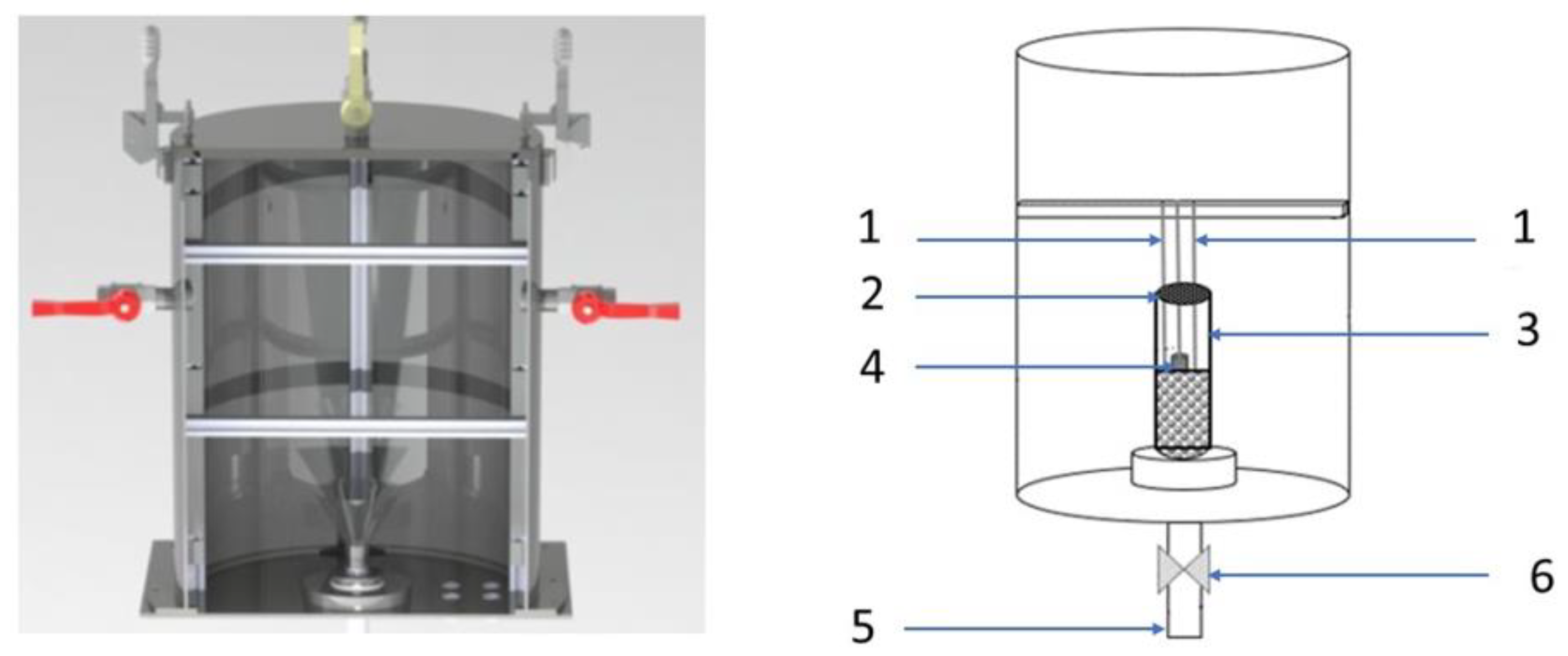
2.1. Prototype Test Stand: Intensified Heat Transfer Adsorption Bed (IHTAB) Reactor
2.2. Characteristics of Materials
3. Results and Discussion
4. Conclusions
- Fluidization resulted in an increased convective heat transfer coefficient for each examined adsorption bed sample.
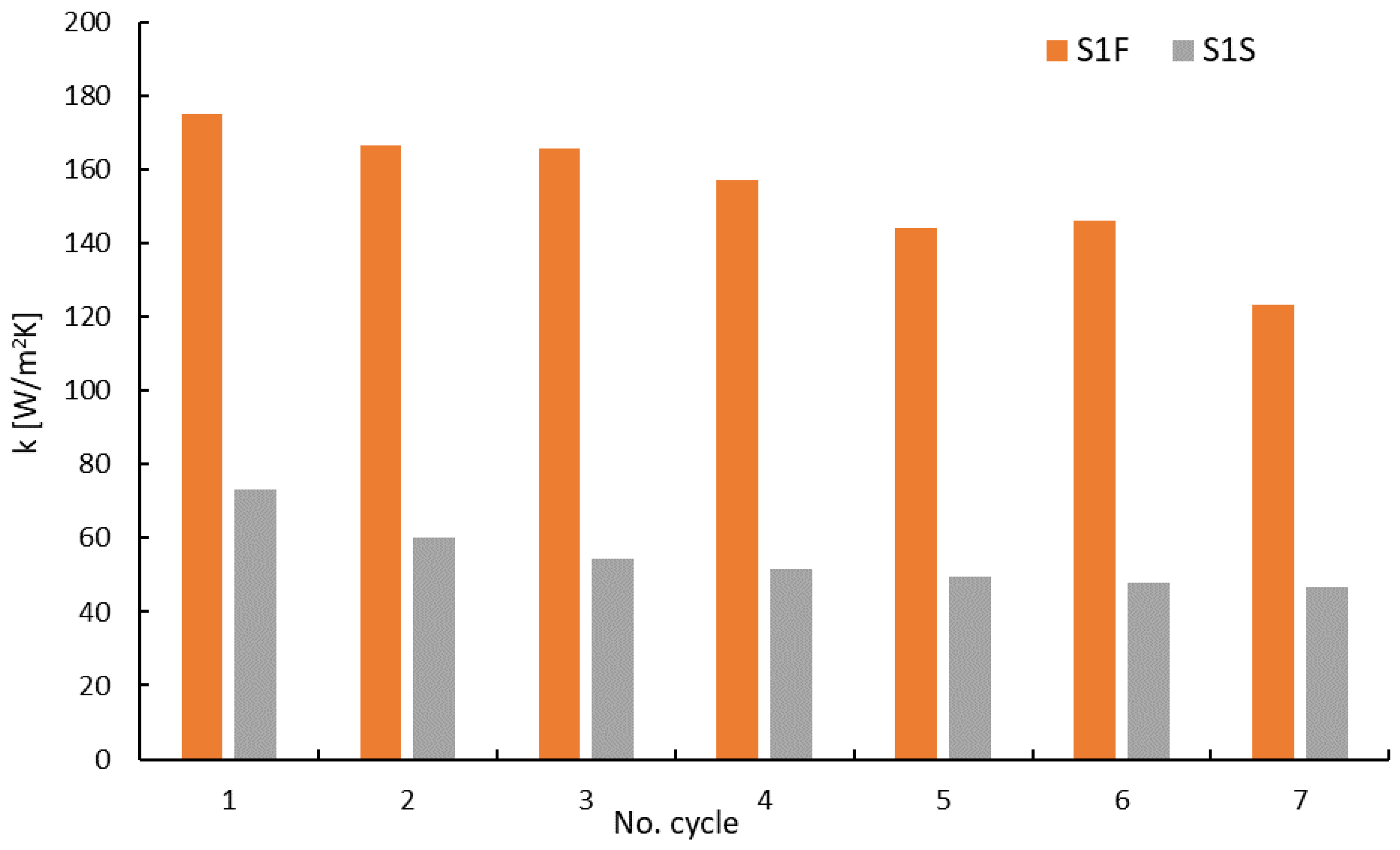
- For reference adsorption bed samples without thermal additives (S1S and S1F), the heat transfer coefficient reached a maximum of 70 W/m2 K in the fixed state, and for the fluidized state, it was approximately 176.5 W/m2 K. Moreover, in each subsequent adsorption cycle, the fluidized bed was characterized by better thermal conditions than the fixed state.
- A minimum value of k equal to 36.9 W/m2 K was registered in the fixed state for the S2S sample consisting of silica gel with a 5% addition of aluminum particles.
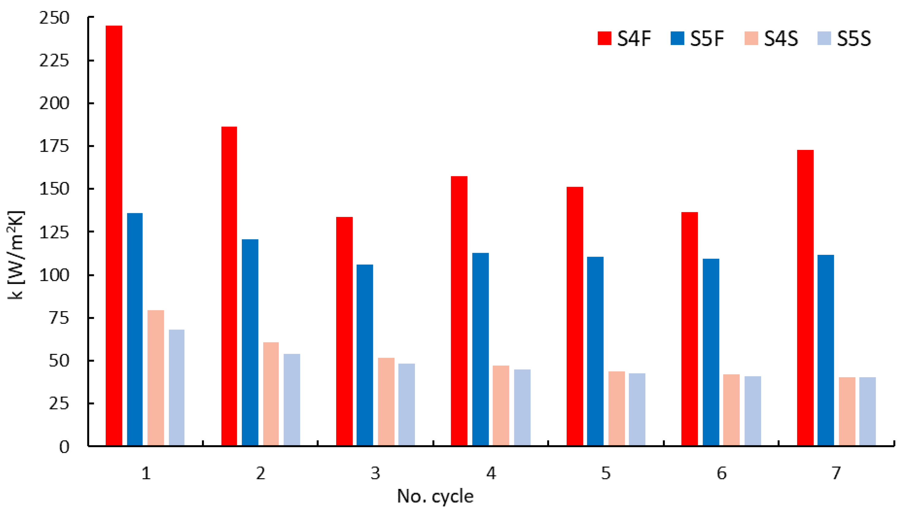
- A maximum value of the heat transfer coefficient equal to 245.4 W/m2 K was achieved in the fluidized state for the S4F sample composed of silica gel with a 5% carbon nanotube additive.
Author Contributions
Funding
Data Availability Statement
Conflicts of Interest
Glossary
| AB | Absorption |
| AD | Adsorption |
| CC | Cooling Capacity, W |
| specific heat of chilled water, J/kgK | |
| specific heat of hot water, J/kgK | |
| CFB | Circulating Fluidized Bed |
| COP | Coefficient of Performance |
| F | Fluidized state |
| HP | Heating Power, W |
| IHTAB | Intensified Heat Transfer Adsorption Bed |
| k | convective heat transfer coefficient, W/m2·K |
| Mtotal | total mass of adsorbent kg, |
| a mass flow of chilled water, kg/s | |
| a mass flow of hot water, kg/s | |
| S | Stationary state (fixed) |
| SCP | Specific Cooling Power, W/kg |
| S1–S5 | Samples’ identification |
| temperature difference at the inlet and outlet of the evaporator; | |
| temperature difference at the inlet and outlet of the heat exchanger built in the adsorption bed; | |
| ρbulk | Bulk density of the silica gel, kg/m3 |
| ρapp | Apparent density of the silica gel, kg/m3 |
| ε | porosity of the silica gel, - |
References
- Windram, C. Climate change policy & global energy projections—After Kyoto. Renew. Energy Technol. Policies Sustain. Dev. 1999, 341–344. [Google Scholar]
- Chepeliev, M.; van der Mensbrugghe, D. Global fossil-fuel subsidy reform and Paris Agreement. Energy Econ. 2020, 85, 104598. [Google Scholar] [CrossRef]
- Mundaca, G. How much can CO2 emissions be reduced if fossil fuel subsidies are removed? Energy Econ. 2017, 64, 91–104. [Google Scholar] [CrossRef]
- He, B.; Pan, Q.J.; Deng, Z.Q. Product carbon footprint for product life cycle under uncertainty. J. Clean. Prod. 2018, 187, 459–472. [Google Scholar] [CrossRef]
- Chen, J.D.; Fan, W.; Li, D.; Liu, X.; Song, M.L. Driving factors of global carbon footprint pressure: Based on vegetation carbon sequestration. Appl. Energy 2020, 267, 114914. [Google Scholar] [CrossRef]
- Wu, J.Z.; Liu, G.H.; Marson, A.; Fedele, A.; Scipioni, A.; Manzardo, A. Mitigating environmental burden of the refrigerated transportation sector: Carbon footprint comparisons of commonly used refrigeration systems and alternative cold storage systems. J. Clean. Prod. 2022, 372, 133514. [Google Scholar] [CrossRef]
- Di Filippo, R.; Bursi, O.S.; Di Maggio, R. Global warming and ozone depletion potentials caused by emissions from HFC and CFC banks due structural damage. Energy Build. 2022, 273, 112385. [Google Scholar] [CrossRef]
- Ali, E.S.; Askalany, A.A.; Harby, K.; Diab, M.R.; Alsaman, A.S. Adsorption desalination-cooling system employing copper sulfate driven by low grade heat sources. Appl. Therm. Eng. 2018, 136, 169–176. [Google Scholar] [CrossRef]
- Mitra, S.; Thu, K.; Saha, B.B.; Dutta, P. Performance evaluation and determination of minimum desorption temperature of a two-stage air cooled silica gel/water adsorption system. Appl. Energy 2017, 206, 507–518. [Google Scholar] [CrossRef]
- Pereira, M.A.; Marques, R.C. Sustainable water and sanitation for all: Are we there yet? Water Res. 2021, 207, 117765. [Google Scholar] [CrossRef]
- Hua, W.S.; Xu, H.J.; Xie, W.H. Review on adsorption materials and system configurations of the adsorption desalination applications. Appl. Therm. Eng. 2022, 204, 117958. [Google Scholar] [CrossRef]
- Zohir, A.E.; Ali, E.S.; Farid, A.M.; Elshaer, R.N.; Mohammed, R.H.; Alsaman, A.S.; El-Ghetany, H.H.; Askalany, A.A. A state-of-the-art of experimentally studied adsorption water desalination systems. Int. J. Energy Environ. Eng. 2023, 14, 573–599. [Google Scholar] [CrossRef]
- Ghazy, M.; Ibrahim, E.M.M.; Mohamed, A.S.A.; Askalany, A.A. Experimental investigation of hybrid photovoltaic solar thermal collector (PV/T)-adsorption desalination system in hot weather conditions. Energy 2022, 254, 124370. [Google Scholar] [CrossRef]
- Ben Hamida, M.B.; Alshammari, F.; Alatawi, I.; Alhadri, M.; Almeshaal, M.A.; Hajlaoui, K. Potential Of Tubular Solar Still With Rectangular Trough For Water Production Under Vacuum Condition. Therm. Sci. 2022, 26, 4271–4283. [Google Scholar]
- Ben Hamida, M.B. Numerical analysis of tubular solar still with rectangular and cylindrical troughs for water production under vacuum. J. Taibah Univ. Sci. 2023, 17, 2159172. [Google Scholar] [CrossRef]
- Wang, R.Z.; Oliveira, R.G. Adsorption refrigeration—An efficient way to make good use of waste heat and solar energy. Prog. Energy Combust. Sci. 2006, 32, 424–458. [Google Scholar] [CrossRef]
- Tokarev, M.M.; Gordeeva, L.G.; Grekova, A.D.; Aristov, Y.I. Adsorption cycle “heat from cold” for upgrading the ambient heat: The testing a lab-scale prototype with the composite sorbent CaClBr/silica. Appl. Energy 2018, 211, 136–145. [Google Scholar] [CrossRef]
- Lim, K.; Lee, S.; Lee, C. An experimental study on the thermal performance of ground heat exchanger. Exp. Therm. Fluid Sci. 2007, 31, 985–990. [Google Scholar] [CrossRef]
- Chen, W.D.; Chua, K.J. Parameter analysis and energy optimization of a four-bed, two-evaporator adsorption system. Appl. Energy 2020, 265, 114842. [Google Scholar] [CrossRef]
- Sah, R.P.; Choudhury, B.; Das, R.K. Study of a two-bed silica gel-water adsorption chiller: Performance analysis. Int. J. Sustain. Energy 2018, 37, 30–46. [Google Scholar] [CrossRef]
- Alsarayreh, A.A.; Al-Maaitah, A.; Attarakih, M.; Bart, H.J. Performance Analysis of Variable Mode Adsorption Chiller at Different Recooling Water Temperatures. Energies 2021, 14, 3871. [Google Scholar] [CrossRef]
- Sidhareddy, M.; Tiwari, S.; Phelan, P.; Bellos, E. Comprehensive review on adsorption cooling systems and its regeneration methods using solar, ultrasound, and microwave energy. Int. J. Refrig. 2023, 146, 174–201. [Google Scholar] [CrossRef]
- Pajdak, A.; Kulakowska, A.; Liu, J.F.; Berent, K.; Kudasik, M.; Krzywanski, J.; Kalawa, W.; Sztekler, K.; Skoczylas, N. Accumulation and Emission of Water Vapor by Silica Gel Enriched with Carbon Nanotubes CNT-Potential Applications in Adsorption Cooling and Desalination Technology. Appl. Sci. 2022, 12, 5644. [Google Scholar] [CrossRef]
- Boruta, P.; Bujok, T.; Sztekler, K. Adsorbents, Working Pairs and Coated Beds for Natural Refrigerants in Adsorption Chillers-State of the Art. Energies 2021, 14, 4707. [Google Scholar] [CrossRef]
- Shaaban, M.; Elsheniti, M.B.; Rezk, A.; Elhelw, M.A.; Elsamni, O.A. Performance investigation of adsorption cooling and desalination systems employing thermally enhanced copper foamed bed coated with SAPO-34 and CPO-27(Ni). Appl. Therm. Eng. 2022, 205, 118056. [Google Scholar] [CrossRef]
- Grabowska, K.; Sztekler, K.; Krzywanski, J.; Sosnowski, M.; Stefanski, S.; Nowak, W. Construction of an innovative adsorbent bed configuration in the adsorption chiller part 2. experimental research of coated bed samples. Energy 2021, 215, 119123. [Google Scholar] [CrossRef]
- Sharafian, A.; Fayazmanesh, K.; McCague, C.; Bahrami, M. Thermal conductivity and contact resistance of mesoporous silica gel adsorbents bound with polyvinylpyrrolidone in contact with a metallic substrate for adsorption cooling system applications. Int. J. Heat Mass Transf. 2014, 79, 64–71. [Google Scholar] [CrossRef]
- Li, K.Y.; Luo, W.J.; Tsai, B.Y.; Kuan, Y.D. Performance Analysis of Two-Stage Solid Desiccant Densely Coated Heat Exchangers. Sustainability 2020, 12, 7357. [Google Scholar] [CrossRef]
- Panigrahi, B.; Chen, Y.S.; Luo, W.J.; Wang, H.W. Dehumidification Effect of Polymeric Superabsorbent SAP-LiCl Composite Desiccant-Coated Heat Exchanger with Different Cyclic Switching Time. Sustainability 2020, 12, 9673. [Google Scholar] [CrossRef]
- Sosnowski, M. Evaluation of Heat Transfer Performance of a Multi-Disc Sorption Bed Dedicated for Adsorption Cooling Technology. Energies 2019, 12, 4660. [Google Scholar] [CrossRef]
- Papakokkinos, G.; Castro, J.; Oliet, C.; Oliva, A. Computational investigation of the hexagonal honeycomb adsorption reactor for cooling applications. Appl. Therm. Eng. 2022, 202, 117807. [Google Scholar] [CrossRef]
- Ilis, G.G.; Demir, H.; Mobedi, M.; Saha, B.B. A new adsorbent bed design: Optimization of geometric parameters and metal additive for the performance improvement. Appl. Therm. Eng. 2019, 162, 114270. [Google Scholar] [CrossRef]
- Papakokkinos, G.; Castro, J.; López, J.; Oliva, A. A generalized computational model for the simulation of adsorption packed bed reactors—Parametric study of five reactor geometries for cooling applications. Appl. Energy 2019, 235, 409–427. [Google Scholar] [CrossRef]
- Jodlowski, P.J.; Kurowski, G.; Skoczylas, N.; Pajdak, A.; Kudasik, M.; Jedrzejczyk, R.J.; Kuterasinski, L.; Jelen, P.; Sitarz, M.; Li, A.; et al. Silver and copper modified zeolite imidazole frameworks as sustainable methane storage systems. J. Clean. Prod. 2022, 352, 131638. [Google Scholar] [CrossRef]
- Freni, A.; Sapienza, A.; Glaznev, I.S.; Aristov, Y.I.; Restuccia, G. Experimental testing of a lab-scale adsorption chiller using a novel selective water sorbent “silica modified by calcium nitrate”. Int. J. Refrig. Rev. Int. Du Froid 2012, 35, 518–524. [Google Scholar] [CrossRef]
- Panigrahi, B.; Wang, H.W.; Luo, W.J.; Chou, Y.C.; Chen, J.J. Comparative analysis of the static and dynamic dehumidification performance of metal-organic framework materials. Sci. Technol. Built Environ. 2023, 29, 323–338. [Google Scholar] [CrossRef]
- Bahrehmand, H.; Khajehpour, M.; Bahrami, M. Finding optimal conductive additive content to enhance the performance of coated sorption beds: An experimental study. Appl. Therm. Eng. 2018, 143, 308–315. [Google Scholar] [CrossRef]
- Li, M.L.; Zhao, Y.N.; Long, R.; Liu, Z.C.; Liu, W. Gradient porosity distribution of adsorbent bed for efficient adsorption cooling. Int. J. Refrig. 2021, 128, 153–162. [Google Scholar] [CrossRef]
- Khan, M.Z.I.; Alam, K.C.A.; Saha, B.B.; Akisawa, A.; Kashiwagi, T. Performance evaluation of multi-stage, multi-bed adsorption chiller employing re-heat scheme. Renew. Energy 2008, 33, 88–98. [Google Scholar] [CrossRef]
- Zajaczkowski, B. Optimizing performance of a three-bed adsorption chiller using new cycle time allocation and mass recovery. Appl. Therm. Eng. 2016, 100, 744–752. [Google Scholar] [CrossRef]
- Nikbakhti, R.; Wang, X.L.; Chan, A. Performance optimization of an integrated adsorption-absorption cooling system driven by low-grade thermal energy. Appl. Therm. Eng. 2021, 193, 117035. [Google Scholar] [CrossRef]
- Nikbakhti, R.; Iranmanesh, A. Potential application of a novel integrated adsorption-absorption refrigeration system powered with solar energy in Australia. Appl. Therm. Eng. 2021, 194, 117114. [Google Scholar] [CrossRef]
- Albaik, I.; Al-Dadah, R.; Mahmoud, S.; Solmaz, I. Non-equilibrium numerical modelling of finned tube heat exchanger for adsorption desalination/cooling system using segregated solution approach. Appl. Therm. Eng. 2021, 183, 116171. [Google Scholar] [CrossRef]
- Komeilibirjandi, A.; Raffiee, A.H.; Maleki, A.; Nazari, M.A.; Shadloo, M.S. Thermal conductivity prediction of nanofluids containing CuO nanoparticles by using correlation and artificial neural network. J. Therm. Anal. Calorim. 2020, 139, 2679–2689. [Google Scholar] [CrossRef]
- Grabowska, K.; Sosnowski, M.; Krzywanski, J.; Sztekler, K.; Kalawa, W.; Zylka, A.; Nowak, W. The Numerical Comparison of Heat Transfer in a Coated and Fixed Bed of an Adsorption Chiller. J. Therm. Sci. 2018, 27, 421–426. [Google Scholar] [CrossRef]
- Krzywanski, J.; Skrobek, D.; Zylka, A.; Grabowska, K.; Kulakowska, A.; Sosnowski, M.; Nowak, W.; Blanco-Marigorta, A.M. Heat and mass transfer prediction in fluidized beds of cooling and desalination systems by AI approach. Appl. Therm. Eng. 2023, 225, 120200. [Google Scholar] [CrossRef]
- Krzywanski, J.; Czakiert, T.; Nowak, W.; Shimizu, T.; Zylka, A.; Idziak, K.; Sosnowski, M.; Grabowska, K. Gaseous emissions from advanced CLC and oxyfuel fluidized bed combustion of coal and biomass in a complex geometry facility: A comprehensive model. Energy 2022, 251, 123896. [Google Scholar] [CrossRef]
- Chiang, Y.C.; Chen, C.H.; Chen, S.L. Circulating inclined fluidized beds with application for desiccant dehumidification systems. Appl. Energy 2016, 175, 199–211. [Google Scholar] [CrossRef]
- Krzywanski, J.; Sztekler, K.; Szubel, M.; Siwek, T.; Nowak, W.; Mika, L. A Comprehensive, Three-Dimensional Analysis of a Large-Scale, Multi-Fuel, CFB Boiler Burning Coal and Syngas. Part 2. Numerical Simulations of Coal and Syngas Co-Combustion. Entropy 2020, 22, 856. [Google Scholar] [CrossRef] [PubMed]
- Khaled, G.; Bourouina-Bacha, S.; Sabiri, N.E.; Tighzert, H.; Kechroud, N.; Bourouina, M. Simplified correlations of axial dispersion coefficient and porosity in a solid-liquid fluidized bed adsorber. Exp. Therm. Fluid Sci. 2017, 88, 317–325. [Google Scholar] [CrossRef]
- Qian, S.X.; Ling, J.Z.; Muehlbauer, J.; Hwang, Y.H.; Radermacher, R. Study on high efficient heat recovery cycle for solid-state cooling. Int. J. Refrig. Rev. Int. Du Froid 2015, 55, 102–119. [Google Scholar] [CrossRef]
- Qi, B.J.; Yan, Y.; Zhang, W.B.A.; Wang, X.Y. Measurement of biomass moisture content distribution in a fluidised bed dryer through electrostatic sensing and digital imaging. Powder Technol. 2021, 388, 380–392. [Google Scholar] [CrossRef]
- Lasek, L.; Zylka, A.; Krzywanski, J.; Skrobek, D.; Sztekler, K.; Nowak, W. Review of Fluidized Bed Technology Application for Adsorption Cooling and Desalination Systems. Energies 2023, 16, 7311. [Google Scholar] [CrossRef]
- Krzywanski, J.; Grabowska, K.; Sosnowski, M.; Zylka, A.; Kulakowska, A.; Czakiert, T.; Sztekler, K.; Wesolowska, M.; Nowak, W. Heat Transfer in Adsorption Chillers with Fluidized Beds of Silica Gel, Zeolite, and Carbon Nanotubes. Heat Transf. Eng. 2021, 43, 172–182. [Google Scholar] [CrossRef]
- Grabowska, K.; Zylka, A.; Kulakowska, A.; Skrobek, D.; Krzywanski, J.; Sosnowski, M.; Ciesielska, K.; Nowak, W. Experimental Investigation of an Intensified Heat Transfer Adsorption Bed (IHTAB) Reactor Prototype. Materials 2021, 14, 3520. [Google Scholar] [CrossRef]
- Rozenek, M. Manual of the Experimental Test Stand; Automatic Solutions sp. z o.o.: Marcinowice, Poland, 2019. [Google Scholar]
- Dawoud, B. Water vapor adsorption kinetics on small and full scale zeolite coated adsorbers; A comparison. Appl. Therm. Eng. 2013, 50, 1645–1651. [Google Scholar] [CrossRef]
- Younes, M.M.; El-Sharkawy, I.I.; Kabeel, A.E.; Saha, B.B. A review on adsorbent-adsorbate pairs for cooling applications. Appl. Therm. Eng. 2017, 114, 394–414. [Google Scholar] [CrossRef]
- Shmroukh, A.N.; Ali, A.H.H.; Ookawara, S. Adsorption working pairs for adsorption cooling chillers: A review based on adsorption capacity and environmental impact. Renew. Sustain. Energy Rev. 2015, 50, 445–456. [Google Scholar] [CrossRef]


| Parameter | Unit | Value |
|---|---|---|
| Name of equipment | - | Intensified Heat Transfer Adsorption Bed (IHTAB) Reactor |
| Serial number | - | 240/2019 |
| Validation year | 2019 | |
| electrical supply | (VAC) | Single-phase TN S 230 V AC network |
| Dimensions (width/length/height) | (mm) | 1280/700/1550 |
| Total mass | (kg) | ~160 |
| Adsorption chamber dimensions (height/diameter) | mm | 520/404 |
| Desorption chamber dimensions (height/diameter) | mm | 418/404 |
| Sample Identification | Composition of Adsorption Bed Sample |
|---|---|
| S1 | Silica gel 100% − reference sample |
| S2 | Silica gel + Aluminum particles 5% |
| S3 | Silica gel + Aluminum particles 15% |
| S4 | Silica gel + Carbon nanotube particles 5% |
| S5 | Silica gel + Carbon nanotube particles 15% |
| Material | Particle Size µm | Density kg/m3 | Apparent Density kg/m3 | Bulk Density kg/m3 | Thermal Conductivity W/m·K | Thermal Diffusivity mm2/s | Sphericity - |
|---|---|---|---|---|---|---|---|
| Silica gel | 160–200 | 2200 | 1100 | 750 | 0.176 | 0.137 | 0.70 |
| Specific Surface Area m2/g | Porosity (ε) - | Av. Pore Diameter nm | Total Pore Volume cm3/g (Vp) |
|---|---|---|---|
| 800 | 0.44 | 2.45 | 0.404 |
| Material | Particle Size µm | Density kg/m3 | Thermal Conductivity W/m·K | Thermal Diffusivity mm2/s | Sphericity - |
|---|---|---|---|---|---|
| Aluminum particles | 45–300 | 2720 | 237 | 97.1 | 0.45 |
| Carbon nanotubes | 0.005–10 | 2600 | 2320 | 460 | <0.1 |
Disclaimer/Publisher’s Note: The statements, opinions and data contained in all publications are solely those of the individual author(s) and contributor(s) and not of MDPI and/or the editor(s). MDPI and/or the editor(s) disclaim responsibility for any injury to people or property resulting from any ideas, methods, instructions or products referred to in the content. |
© 2024 by the authors. Licensee MDPI, Basel, Switzerland. This article is an open access article distributed under the terms and conditions of the Creative Commons Attribution (CC BY) license (https://creativecommons.org/licenses/by/4.0/).
Share and Cite
Grabowska, K.; Krzywanski, J.; Zylka, A.; Kulakowska, A.; Skrobek, D.; Sosnowski, M.; Ščurek, R.; Nowak, W.; Czakiert, T. Implementation of Fluidized Bed Concept to Improve Heat Transfer in Ecological Adsorption Cooling and Desalination Systems. Energies 2024, 17, 379. https://doi.org/10.3390/en17020379
Grabowska K, Krzywanski J, Zylka A, Kulakowska A, Skrobek D, Sosnowski M, Ščurek R, Nowak W, Czakiert T. Implementation of Fluidized Bed Concept to Improve Heat Transfer in Ecological Adsorption Cooling and Desalination Systems. Energies. 2024; 17(2):379. https://doi.org/10.3390/en17020379
Chicago/Turabian StyleGrabowska, Karolina, Jaroslaw Krzywanski, Anna Zylka, Anna Kulakowska, Dorian Skrobek, Marcin Sosnowski, Radomir Ščurek, Wojciech Nowak, and Tomasz Czakiert. 2024. "Implementation of Fluidized Bed Concept to Improve Heat Transfer in Ecological Adsorption Cooling and Desalination Systems" Energies 17, no. 2: 379. https://doi.org/10.3390/en17020379
APA StyleGrabowska, K., Krzywanski, J., Zylka, A., Kulakowska, A., Skrobek, D., Sosnowski, M., Ščurek, R., Nowak, W., & Czakiert, T. (2024). Implementation of Fluidized Bed Concept to Improve Heat Transfer in Ecological Adsorption Cooling and Desalination Systems. Energies, 17(2), 379. https://doi.org/10.3390/en17020379