Article

Fast Analytic–Numerical Algorithms for Calculating Mutual and Self-Inductances of Air Coils

Faculty of Electrical Engineering, West Pomeranian University of Technology, Sikorskiego 37, 70-313 Szczecin, Poland
Energies 2024, 17(2), 325; https://doi.org/10.3390/en17020325
Submission received: 30 November 2023 / Revised: 31 December 2023 / Accepted: 6 January 2024 / Published: 9 January 2024
(This article belongs to the Section F: Electrical Engineering)

Abstract

:
This paper deals with a method of calculating the mutual and self-inductances of various air coils located arbitrarily in space. Known elementary solutions (the Biot–Savart formulas) were used to determine the magnetic field of infinitely thin current loops and infinitely thin wires of finite length magnetically linking other coils. Unlike commonly used algorithms, these elementary solutions were not extensively transformed analytically but were used to perform calculations via direct numerical integration. This enabled the very quick and accurate obtaining of the self-inductance values, as well as determining the dependence of mutual inductances on the positions of both coils. This method allows for the analysis of different coil configurations (misaligned coils, inclined to each other, etc.) that other methods do not cover. It also enables the determination of the forces acting on the coils, as well as the calculation of the magnetic field distribution from any coil configuration. The obtained results were compared with those presented by other authors (both computational and measurement results).

1. Introduction

Nowadays, contactless energy transfer (CET) offers great opportunities to power various types of mobile devices. A typical inductive CET system consists of a primary side DC/AC resonant converter, a transformer, and an AC/DC secondary system that converts the high-frequency AC energy to meet the requirements specified by the load parameters. The secondary side is not connected electrically to the primary side, which has many obvious advantages. High-power CET systems are used in the automotive and transportation industries, among others, as battery chargers [1,2,3].
Many CET devices use magnetically coupled air coils. These include wireless energy transfer, various types of accelerators, electronic systems, and biomedical [4,5] and robotics applications. Some applications use a coreless transformer based on a printed circuit board winding layout without a ferrite core [6]. The advantages of coreless coils are their lower weight and increased mechanical durability. Moreover, designing the shape is simpler and gives much more opportunities to adapt it to the rest of the system. The problems of designing coreless systems are discussed, for example, in articles [7,8,9].
Converting energy in the primary and secondary circuits of CET systems is a standard and well-recognized task for designers of power electronic systems. Calculating the magnetic coupling of air coils is also a well-developed scientific topic; however, due to the variety of newly designed coils (their shapes and tasks), as well as the possibility of their arbitrary mutual position (any misalignment), it is necessary to develop fast and accurate algorithms for calculating their mutual and self-inductances.

2. Principles for Calculating the Mutual and Self-Inductances of Air Coils

Methods for calculating the mutual and self-inductances of different air coils have been presented in many papers [10,11,12,13,14,15,16,17,18,19,20,21,22,23,24,25,26,27,28,29,30,31].
First, it is worth mentioning the fundamental paper by F.W. Grover [10], who presented a method for calculating the mutual inductance of circular filaments in any position. He used equations that describe the magnetic field of elementary current loops to determine their mutual inductances for various mutual positions. A similar methodology was also used in this study.
The article [11] by J.T. Conway shows the use of Bessel functions to calculate the inductance of different non-coaxial coils. A continuation of this article is paper [12], in which elliptic integrals were used to calculate inductances. In [13], the inductance calculations for coils of parallel axes using Bessel and Struve functions are shown.
The articles by Babic and his various co-authors [14,15,16,17,18,19,20,21] also give solutions to many basic problems of calculating the mutual and self-inductances of different coils in any mutual position.
It is also worth mentioning article [22], in which the authors developed a fast and effective algorithm for calculating the inductance of coaxial coils by integrating appropriate elementary solutions. The authors of [23] also described a method for calculating mutual inductances for coils with misalignment by integrating elementary field solutions.
Most of the above articles mainly discuss the theoretical problems of calculating mutual and self-inductances. However, many articles also publish the results of measurement tests of the mutual and self-inductances of various coil configurations—this allows for the verification of the results of theoretical considerations.
For example, article [24] presents a three-dimensional analytical model for calculating the mutual inductance of coils with any misalignment. This article presents a measurement stand and the results of measurements of mutual inductance of various rectangular coils, also with a magnetic screen.
Very complicated calculation algorithms for mutual and self-inductances are presented in articles [25,26]. In both of them, a comparison of the calculation results with the measurement results is given, showing a very high consistency between the results.
Article [27] presents inductance calculation algorithms for various unusual air coils (rounded rectangular coils, circular coils, rectangular coils, racetrack coils) using the Fourier transform. The obtained results were verified via comparison with the measurement results for various mutual positions of the coils (coaxial alignment and lateral misalignment).
Article [28] presents the analytical method of mutual inductance calculation between two rectangular spiral coils with misalignments for wireless power applications. The calculations were confirmed by measuring the mutual inductances of the rectangular spiral coils fabricated on a printed circuit board.
Article [29] uses inverse hyperbolic functions to calculate the mutual and self-inductances of coaxial circular filamentary coils, thin-wall solenoids, and disk coils. This article does not present its own experimental research but uses measurement results carried out by other researchers and compares the obtained results with many benchmark problems.
A deeper discussion of the above articles is provided later in this paper. There are, of course, many other important articles on this topic, but it is not possible to discuss them here.
Much simpler algorithms are proposed in this paper, primarily involving the calculation of the flux linkage for various coil configurations. Analytical solutions for simple coil configurations and numerical integration of these elementary solutions were used to create a computational tool that allows for quick and accurate calculations of the mutual and self-inductances of various air coils for any of their mutual positions. The obtained results were compared with those presented by other authors, focusing mainly on the results supported by appropriate measurements or on the results of solutions to benchmark problems that were previously analyzed by many authors.

Basics of Magnetic Field Theory Used for Inductance Calculations

The magnetic energy W m of a system carrying a current I (with a uniform current density J ) can be calculated as a volume integral over the magnetic energy density. For arrangements with μ = μ 0 in the entire space with volume V , it reads
W m = 1 2 V B H d V ,
where B and H are the magnetic induction and magnetic field strength vectors, respectively.
Using the definition of vector potential A :
B = rot A , div A = 0
and Maxwell’s first equation:
rot H = J
the following form of Equation (1), which is very useful for calculating the magnetic field energy, is obtained:
W m = 1 2 V A   J d V .
Formula (4), unlike Formula (1), requires integration only in areas where the electric current density is different from zero, which greatly speeds up calculations. Finally, the inductance of the wire carrying the current I can be calculated from the following formula:
L = 2 W m / I 2 .
In the case of two independent electrical circuit leading currents I 1 and I 2 (with the current densities J 1 and J 2 , respectively), the formula for the magnetic energy can be written as follows:
W m = 1 2 V B H d V = 1 2 V ( B 1 + B 2 ) ( H 1 + H 2 ) d V = 1 2 V ( B 1 H 1 + B 2 H 2 + B 1 H 2 + B 2 H 1 ) d V = = 1 2 L 1 I 1 2 + 1 2 L 2 I 2 2 + 1 2 M 1 , 2 I 1 I 2 + 1 2 M 1 , 2 I 1 I 2 .
The integral V B 1 H 2 d V in Formula (6) can be written according to Equation (4) as
V B 1 H 2 d V = V A 1 J 2 d V .
Formula (7) makes it possible to calculate the mutual inductance of two magnetically coupled circuits using
M 1 , 2 = 1 I 1 I 2 V A 1 J 2 d V .
Integration in Formula (8) should also be carried out only in areas where the current density J 2 is different from zero.
Formulas (5) and (8) enable the easy calculation of mutual and self-inductances in systems where the vector potential has only one component. It can be given analytically or calculated numerically.

3. Cylindrical Air Coils

This chapter presents equations and numerical algorithms enabling the calculation of the mutual and self-inductances of various configurations of cylindrical air coils with a rectangular cross-section.

3.1. Magnetic Field of Cylindrical Coils

Figure 1a shows a system of two coaxial cylindrical coils (with rectangular cross-section) marked with the letters P (primary) and S (secondary). To calculate the magnetic field of this coil system, the cross-section of each coil is divided into cylindrical coils with a rectangular cross-section. The problem of determining mutual and self-inductances, as well as the field distribution of such coils, is thus reduced to determining the interactions between elementary thin coaxial coils. A similar approach to this issue was also discussed in articles [30,31].
Figure 1b illustrates the dimensions and discretization of both coils. The inner radii of the coils are denoted by r 1 p and r 1 s , the outer radii by r 2 p and r 2 s , and their heights by 2 h p and 2 h s , respectively. The currents flowing in the coils are marked by I p and I s , respectively. The value of the current flowing in each elementary loop I p d and I s d results from the discretization of the coils. In all considerations of this paper, the center of the primary coil is always located in the center of the coordinate system.
The proper selection of the values of the discretization parameters d r p , d z p , d r s , d z s is a key issue in determining the accuracy of this algorithm. In each of the presented solutions, the obtained results were tested depending on the type of discretization. Due to the very high speed of the algorithm, it was possible to achieve very fine discretization of all areas. In some cases, this discretization should correspond to the actual arrangement of the turns in the coils.
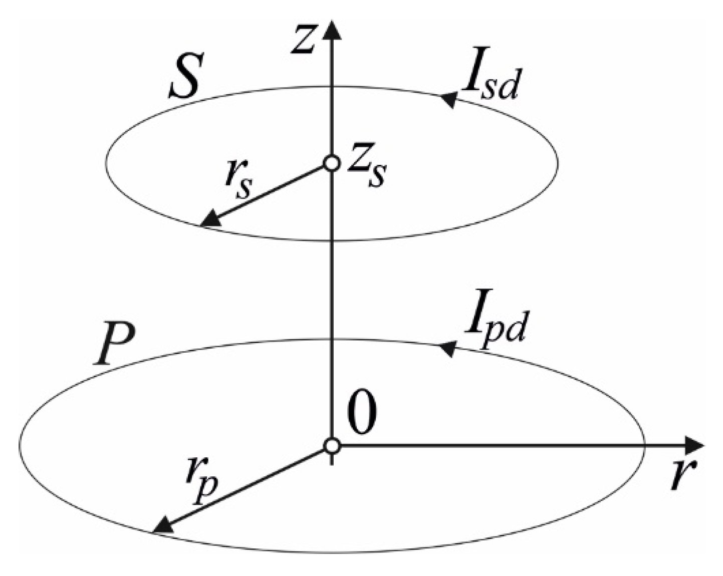
Figure 2 shows two infinitesimally thin coaxial current loops of radii r p and r s , respectively. The center of the primary loop is located in the center of the coordinate system and the center of the secondary loop is located at ( 0 , z s ) .
To calculate the magnetic field of the primary coil, the formulas for the vector potential of infinitely thin current loops from [32] (p. 260) were used. The formulas in [32] also take into account the singularity in the potential formula for r = 0 . The elementary vector potential of the partial current loop with the current I p d of the primary coil with the radius r p can be written as follows [32]:
d A p = μ 0 I p d 2 π r p r K ( u ) 2 u u E ( u ) 2 u d r p d z p ,
where
u = 4 r r p ( r + r p ) 2 + z 2 , I p d = I p 2 h p ( r 2 p r 1 p )
and K ( u ) and E ( u ) are elliptic integrals of the first and second kind, respectively.
The total vector potential of the primary coil can be calculated using the following integral:
A p = r 1 p r 2 p h p h p d A p .
For the magnetic energy, we obtain
W m = 1 2 V A p I p d d V = r 1 p r 2 p h p h p A p I p d π d r d z = r 1 p r 2 p h p h p r 1 p r 2 p h p h p d A p I p d π r d r d z .
Finally, the self-inductance of the primary coil can be calculated as in Equation (5). The self-inductance of the secondary coil is calculated in the same way (after moving it to the center of the coordinate system). The mutual inductance between both coils is obtained using Formula (8), whereby the energy is calculated using Formula (12) (after changing one of the integration surfaces to the secondary coil area).
The number of turns of the primary winding N p and secondary winding N s should also be considered in the calculations of inductances—it is necessary to multiply the obtained results by the square of the number of turns for self-inductances and by the product of the number of turns of the primary and secondary windings for mutual inductances. Determining the fourfold integral (12) when calculating the inductance is the main problem of this method. To shorten the calculation time, various approximations of the elliptic integrals K ( u ) and E ( u ) were tested. Finally, the formulas given in [33] (pages 591 and 592) were used:
K ( u ) = a 0 + a 1 w + a 2 w 2 + a 3 w 3 + a 4 w 4 + b 0 + b 1 w + b 2 w 2 + b 3 w 3 + b 4 w 4 ln 1 / w ,
E ( u ) = c 0 + c 1 w + c 2 w 2 + c 3 w 3 + c 4 w 4 + d 0 + d 1 w + d 2 w 2 + d 3 w 3 + d 4 w 4 ln 1 / w .
The coefficient values a 0 a 4 , b 0 b 4 , c 0 c 4 , d 0 d 4 are given in [33] and w = 1 u 2 . The error of this approximation is less than 2 × 10⁻⁸.

3.2. Comparison with Results Obtained by Other Authors and the Finite Element Method

The method was verified by comparing the results obtained by other authors, as well as by calculations using the finite element method (FEM). Article [22] shows a method for precisely calculating the mutual inductances of different cylindrical coaxial coils. This article compares its own results with nine results obtained by other authors, and thus, it provides a good summary of the topic. Here, a comparison of selected configurations is shown. For example, in [22], the mutual inductance was calculated for coils with the following dimensions: r 1 p = 0.3 m ,   r 2 p = 0.4 m ,   r 1 s = 0.1 m ,   r 2 s = 0.2 m ,   h p = 0.05 m ,   h s = 0.05 m ,   z s = 0.2 m ,   N p = 100 , and N s = 100 .
Article [22] gives a result of the mutual inductance M = 0.8454457615296840   mH (page 4901309, Table II, case 1). An identical value (16 significant places) was obtained in paper [13] (page 81, Table VI, case 1). In article [15], eight significant places in the mutual inductance value are identical (page 1664), but the result gives the value of the mutual inductance in μ H and not in mH . It also seems that providing so many significant places in the result probably does not make much sense due to the limited calculation accuracy—the accuracy of 7–9 places appears to be entirely adequate. The method proposed here gave a result of M = 0.84544578   mH .
All configurations of cylindrical coaxial coils can additionally be quickly analyzed using the two-dimensional (axisymmetric model) FEM to verify different analytical–numerical methods proposed by various authors. The magnetic field distribution in the configuration analyzed above is shown in Figure 3a (both coils are powered by the current having the same value and direction), while the field distributions when powering single coils are shown in Figure 3b,c. The values of self-inductances calculated using the FEM from Formula (5) were equal to L p =   9.5410842   mH and L s = 2.5815732   mH , and the mutual inductance calculated according to Equation (8) was M = 0.84546788   mH . Inductances calculated using FEM were less accurate than using the method of integrating elementary solutions due to the FEM discretization error—it gave an accuracy of approximately 5–6 significant places.
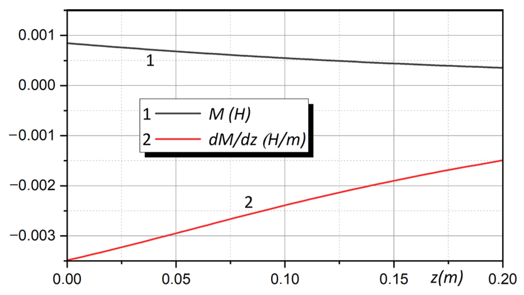
Figure 4 shows the dependence of M and its derivative d M / d z versus the axial displacement of the secondary coil calculated using the proposed method and the FEM (both methods give identical results). The beginning of the trajectory is marked by the point with coordinates ( r = 0 m ,   z s = 0.2 m ) and its end by the point with coordinates ( r = 0 m ,   z s = 0.4 m ) . The derivative of mutual inductance provides information about the forces acting on the coils depending on their relative position (see Section 6).
Papers [10,11,12,13,14,15,16,17,18,19,20,21,22,23,24,25,26,27,28,29,30,31] discuss, among other things, many configurations of cylindrical coaxial coils and determine their mutual inductances. These results were also confirmed using the computational algorithm described herein. This algorithm also enables quick and accurate determination of the mutual inductances during the movement of the secondary coil, as well as the self-inductances of both coils.
The scope of applications of the method presented above is very limited to very basic configurations (cylindrical coaxial coils), but at the same time, this method provides additional opportunities to compare and check the results with 2D-FEM.

3.3. Non-Coaxial Cylindrical Coils

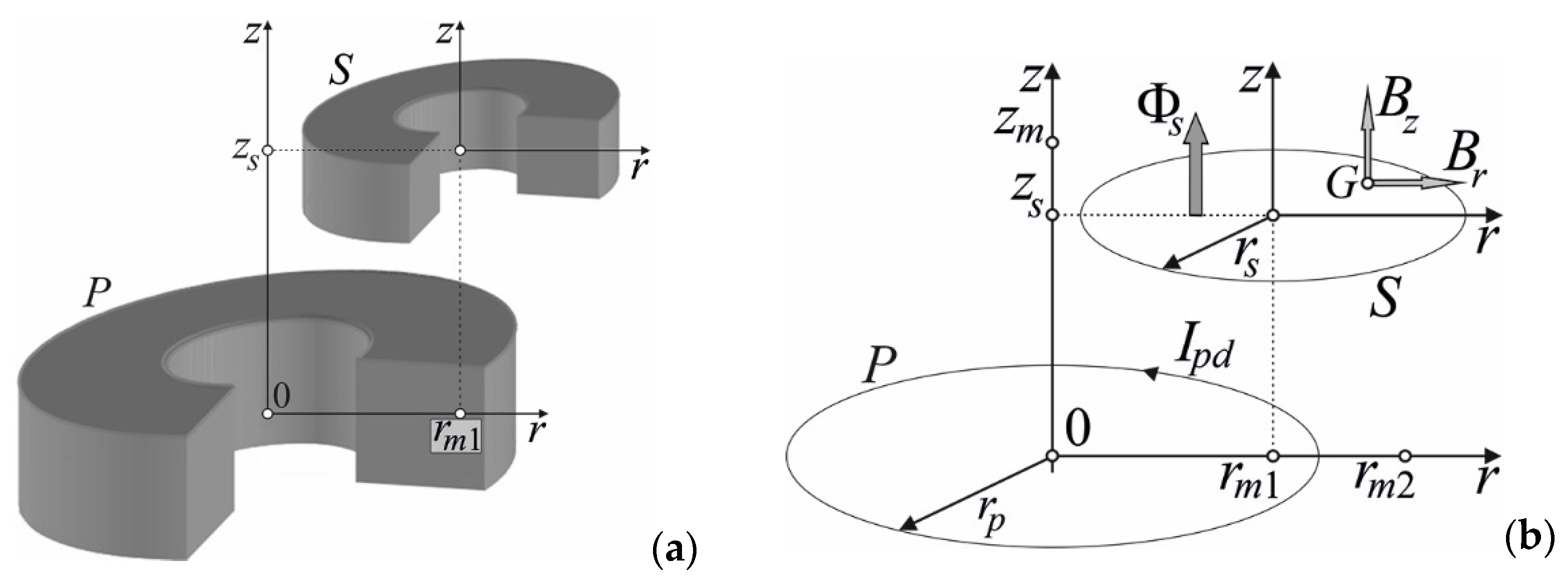
In the case of non-coaxial cylindrical coils, or otherwise arbitrarily located in space, to determine the mutual inductance, the magnetic flux linking the secondary coil when powering the primary coil must be calculated. Figure 5 shows an arrangement of misaligned parallel cylindrical coils. The center of the secondary coil lies at the point with coordinates ( r m 1 , z s ) .
The magnetic field components generated by the primary coil on the surface defined by the elementary loop of the secondary coil (point G) can be determined from the relationship B = rot A :
B r = A p z ; B z = 1 r ( r A p ) r .
Using the dependencies
K ( u ) u = E ( u ) u ( 1 u 2 ) K ( u ) u ; E ( u ) u = E ( u ) K ( u ) u ,
These components can be expressed as
B r = μ 0 I p d z u 4 π r r p r E ( u ) r p 2 + r 2 + z 2 ( r p r ) 2 + z 2 K ( u ) ,
B z = μ 0 I p d u 4 π r p r E ( u ) r p 2 r 2 z 2 ( r p r ) 2 + z 2 + K ( u ) .
The magnetic flux penetrating the surface of the elementary loop of the secondary coil can be calculated as the surface integral of the induction vector perpendicular to this surface:
Φ s = S B z d S .
The mutual inductance between both coils can finally be written as
M = Φ s / I p .
The value of the total magnetic flux linking the secondary coil is calculated by determining the flux generated by each elementary loop of the primary coil in a single loop of the secondary coil. This procedure is repeated for all secondary coil loops and, finally, the value of the flux associated with the secondary coil is obtained.
Formulas (19) and (20) can be used to calculate the mutual inductance for any position of the secondary coil relative to the primary coil (at any coil misalignment). The method was verified by comparing the results obtained by other authors (both computational and measurement results). For example, in article [13], the mutual inductance was calculated for coils with the following dimensions: r 1 p = 7.1247 cm ,   r 2 p = 8.5217 cm ,   r 1 s = 9.69645 cm ,   r 2 s = 13.84935 cm ,   h p = 7.1374 cm ,   h s = 1.2065 cm ,   z s = 7.366 cm ,   r m 1 = 30.988 cm , N p = 1142 , and N s = 516 .
Article [13] gives a result of M = 1.422560384213514 mH (page 79), and the method described here gives a result of M = 1.4225607 mH . The same example was solved in [20], but the result given there of M = 1.422583607   μ H (page 95) has the wrong units ( μ H instead of mH ). The self-inductances of both coils (not calculated in the above papers) were equal to L p = 0.14166241   H and L s = 0.086260334   H , respectively.
The method shown here allows for the easy calculation of mutual inductance values for any secondary coil movement trajectory. The beginning of the trajectory is marked by the point with coordinates ( r m 1 , z s ) and its end by the point with coordinates ( r m 2 , z m ) (see Figure 5).
In [11] (page 1027, Table II), the mutual inductances of two identical coplanar current loops of radius 1 m on top of each other, with the secondary coil moving in the r-direction were calculated. In this case, there was no need to discretize the coil area—the considerations were then carried out automatically for the current loops. Calculations were performed (according to [11]) for the following data: r 2 p = 1   m , r 1 p r 2 p , r 2 s = 1 m , r 1 s r 2 s , h p , h s 0 , z s , z m 0 , r m 1 = 0 m , r m 2 = 20 m , N p = 1 , and N s = 1 . Using the method presented here, the same values were obtained with an accuracy of 7–9 significant places and these results are be presented. Instead, the results of mutual inductance calculations are shown when the secondary coil moved obliquely from the point with coordinates ( r m 1 = 0   m , z s = 0.002   m ) to the point C with coordinates ( r m 2 = 3 m , z m = 1.002 m ) , to the point D with coordinates ( r m 2 = 1 m , z m = ( 3 + 0.002 ) m ) , and axially to the point E with coordinates ( r m 2 = 0 m , z m = 2.002 m ) . In each of these cases, the offset was defined so that the final distance from the center of the secondary coil to the center of the primary coil was the same (2 m). Figure 6a shows the final positions of the secondary coil (points C, D, and E). The proposed method gives the same results by moving the secondary coil axially, as in the method discussed in Section 3.2 (point E). The results for point D lie between the curves for points C and E and are not shown here. Figure 6b gives the values of the mutual inductance of the coils as a function of displacement in generalized coordinates (depending on the direction of movement). This figure also shows the derivative of the mutual inductance in the movement direction, which was used to calculate the forces between both coils (see Section 6). The mutual inductance of the coils decreased significantly when the secondary coil was moved by a distance greater than the radius of the primary coil, and then became negative due to the change in the direction of the magnetic flux in the secondary coil.
The above method can also be used to calculate the mutual inductance of coils arranged arbitrarily in space. Figure 7a shows a system of two such cylindrical coils—the surface of the secondary coil can be inclined to the surface of the primary coil in any way. The center of the secondary coil lies at the point with coordinates ( r m 1 , z s ) and its plane is shifted by angle α in relation to the r-axis. Figure 7b illustrates the system of two elementary current loops of the primary and secondary coils and shows how to calculate the magnetic flux in the secondary coil loop generated by the primary coil loop. To determine this flux, the normal components of the induction vector on the surface of the secondary coil loop must be calculated and integrated over this surface.
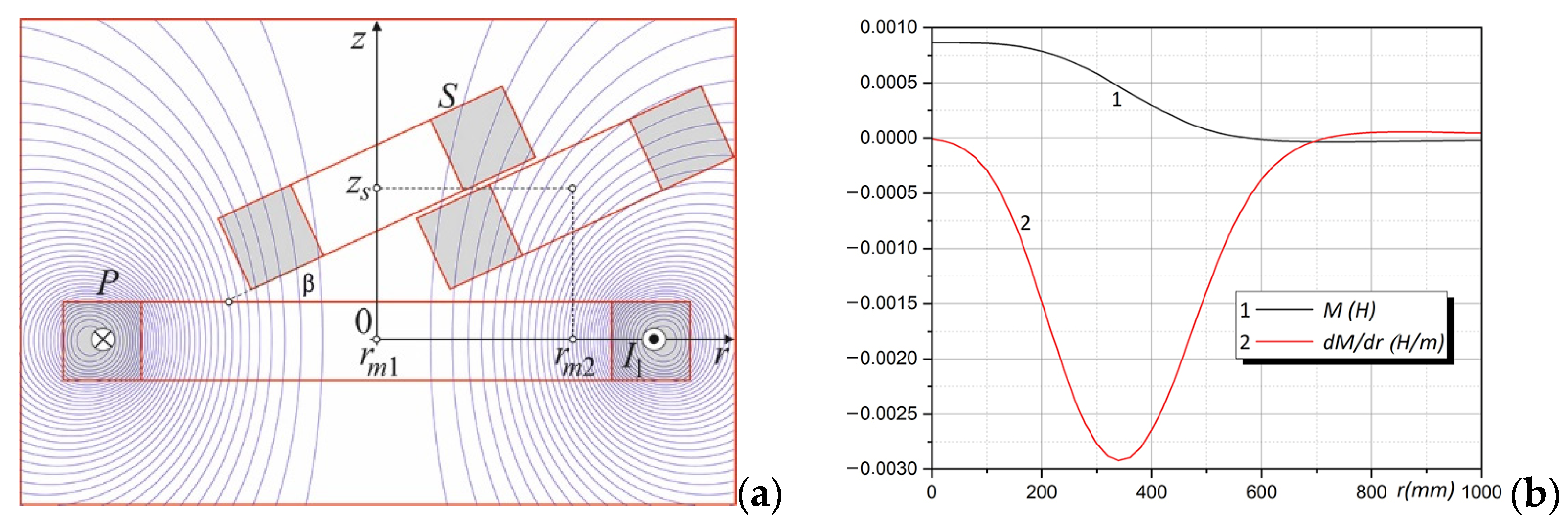
Using this algorithm, the mutual inductance of cylindrical coils can be easily determined for the secondary coil placed in any position, which allows for the determination of characteristics like those shown in Figure 6b. Figure 8a shows an arrangement of coils lying diagonally to each other. The final position of the secondary coil is also marked here. Calculations were made for coils with dimensions from Section 3.2. The inclination angle was β = 15 deg , the coordinates of the starting point were ( r m 1 = 0 m , z s = 0.2 m ) , and the end point coordinates were ( r m 2 = 1 m , z s = 0.2 m ) . Since the distance between the centers of the coils in the analyzed case was small, it was possible to take into account only a small angle β due to the possibility of contact between both coils for its larger values. The results are shown in Figure 8b.
For the oblique relative position of the coils, the mutual inductances were slightly larger for small displacements than in the case of the parallel arrangement; then they decreased significantly; and for larger displacements, they became negative values due to the change in the direction of the magnetic flux in the secondary coil.
As stated above, the efficiency and accuracy of the algorithm depend greatly on the accuracy of the discretization of the primary and secondary coil regions. They also depend strongly on the discretization of the elementary surfaces of the secondary coil current loops (the number of points at which the values of the magnetic field components and the flux orthogonal to this surface are calculated). These are typical problems of all numerical calculations in which numerical integration is performed.
Using Formulas (17) and (18), it is also possible to determine the distribution of the magnetic field generated by systems of any number of cylindrical coils arranged arbitrarily in space (see Section 5).

4. Rectangular Air Coils

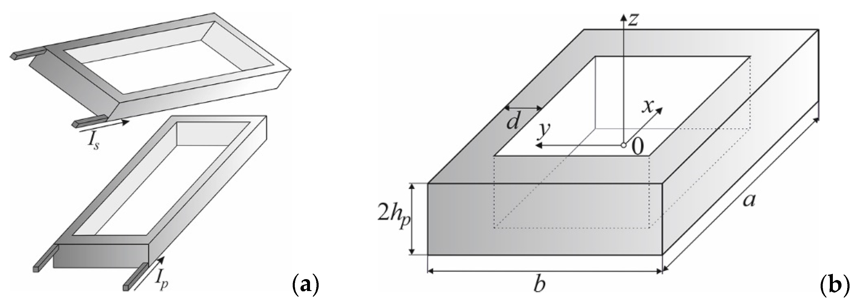
This section deals with the calculation of mutual and self-inductances of rectangular coils in any mutual position, as well as the distribution of magnetic fields of such coil systems. Figure 9a shows a system of rectangular coils, in which the secondary coil is in any position in relation to the primary coil. Figure 9b gives the dimensions of the primary coil.
The use of Formulas (5)–(8) to calculate mutual and self-inductances in this case was impossible and the magnetic flux linkage method described in Section 3.3 was used for the calculations. Figure 9b and Figure 10 illustrate the dimensions and discretization of both coils. The center of the primary coil was located in the center of the coordinate system and the center of the initial position of the secondary coil for coaxial coils was located at ( 0 , z s ) .
To calculate the magnetic field of elementary current loops created by discretization of the primary coil from Figure 10, the Biot–Savart formula defining the magnetic field of an infinitely thin conductor of finite length carrying a current of density J was used (Figure 11a). This made it possible (by integrating the Biot–Savart formula) to determine the values of the magnetic field intensity at any point in space P ( x , y , z ) generated by an infinitely thin band conductor.
The components of the magnetic field H z and H x at point P ( x , y , z ) are written as follows:
H z = J 4 π ln y d + ( x b ) 2 + ( y d ) 2 + ( z e ) 2 y c + ( x b ) 2 + ( y c ) 2 + ( z e ) 2 + ln y d + ( x a ) 2 + ( y d ) 2 + ( z e ) 2 y c + ( x a ) 2 + ( y c ) 2 + ( z e ) 2 ,
H x = J 4 π arctan ( x b ) ( y d ) ( z e ) ( x b ) 2 + ( y d ) 2 + ( z e ) 2 + arctan ( x b ) ( y c ) ( z e ) ( x b ) 2 + ( y c ) 2 + ( z e ) 2 + arctan ( x a ) ( y d ) ( z e ) ( x a ) 2 + ( y d ) 2 + ( z e ) 2 + + arctan ( x a ) ( y c ) ( z e ) ( x a ) 2 + ( y c ) 2 + ( z e ) 2
By changing the variables ( x , y , z ) appropriately, the above equations make it possible to calculate the components of the magnetic field of any surface with the current parallel to a coordinate surface, and finally, the magnetic field of the infinitely thin rectangular current loop from Figure 11b. Thus, the primary coil can be approximated by infinitely thin rectangular band coils or, as in the case of cylindrical coils, by thin rectangular current loops whose geometry and position are determined by the centers of gravity of the discretization elements. The magnetic flux penetrating the surface of the elementary loop of the secondary coil can be calculated as the integral according to Equation (19) for the normal component of the induction vector. This procedure is repeated for all secondary coil loops and the results are averaged. The mutual inductance between both coils can finally be calculated as in Equation (20). Similar methods using the magnetic flux linking other rectangular coils were used, among others, in [30,31].
The method presented in the previous section was used to calculate mutual and self-inductances for rectangular coils in any of their mutual positions. Formulas (21) and (22) were used to calculate the magnetic flux linking the secondary coil.
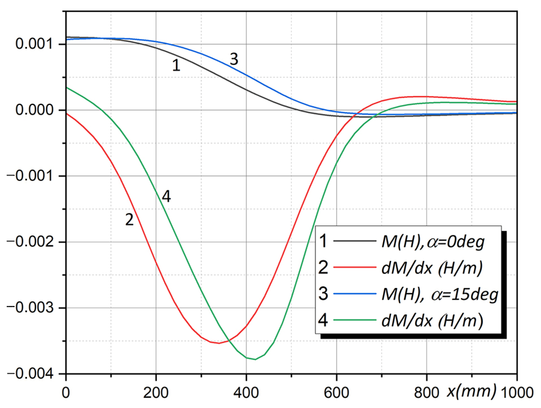
The effectiveness of the method was illustrated using calculations of mutual and self-inductances of two coaxial rectangular coils with identical cross-section dimensions as in Section 3.2 (Figure 3a). The dimensions of the coils were as follows: a p = b p = 0.3 m , d p = 0.1 m , a s = b s = 0.1 m , d s = 0.1 m , h p = 0.05 m , h s = 0.05 m , N p = 100 , and N s = 100 . The center of the primary coil was located in the center of the coordinate system and the center of the secondary coil was located in the initial position at ( x s , z s ) . The coordinates of the starting point for the secondary coil were ( x s = 0 m , z s = 0.2 m ) and the end point coordinates were ( x s = 1 m , z s = 0.2 m ) . Calculations were made for two cases: for parallel coils and coils arranged obliquely to each other, as in Figure 8a for cylindrical coils (the inclination angle β = 15 deg ). The self-inductances of both coils were equal to L p = 11.477932   mH and L s = 3.1543544   mH . These inductances were slightly larger than the inductances of cylindrical coils with the same cross-section because cylindrical coils obviously have a smaller surface area. The results of the mutual inductance calculations are shown in Figure 12.
As can be seen from Figure 12, the relationships between mutual inductances and displacement for parallel and oblique coils were very similar. The mutual inductances for oblique coils had slightly higher values for displacements in the range of 180–650 mm than for parallel coils. The derivative of mutual inductance had a strongly exposed maximum (for a displacement of approx. 330–420 mm), which means that for these displacements, the forces that acted on the coils were significantly increased (see Section 6).
The described method also gives very accurate results when calculating mutual and self-inductances, as well as field distributions for spiral coils, helical coils, very thin coils [31,34], and coils with nonuniform current density distributions [21]. This requires the proper selection of discretization parameters of the coil areas and the magnetic flux integration areas, as well as the selection of equivalent radii when modeling spiral or Archimedean coils [35,36].
Calculations of the mutual and self-inductances of rectangular coils using the finite element method, as well as their measurements, were also carried out in article [8]. Using the method proposed here, results identical to those presented in [8] were obtained with much less work and much faster.

5. Magnetic Field of Current Coils, Permanent Magnets, and High-Temperature Superconductors

Using Formulas (17), (18), (21), and (22), it is also possible to determine the distribution of a magnetic field generated by systems of any number of cylindrical or rectangular coils arranged arbitrarily in space. Figure 13 shows, for example, the distribution of the magnetic field (the normal component of the magnetic induction vector) over circular and rectangular coils depending on the thickness of the electrically conductive area.
The field distributions in Figure 13 are identical to the field distributions of high-temperature bulk superconductors in various saturation states (also in the Meissner state) [22,37,38], as well as the fields of permanent magnets (Figure 13a,b)—the computational model in Figure 11b corresponds directly to the computational model of a permanent magnet. The results shown in Figure 13 are very important in the design of various actuators and levitating systems, as well as in the generation of forces in electric machines with permanent magnets. From them, it can be concluded that fully saturated configurations (Figure 13e,f) are worse for the generation of large forces due to the shape of the magnetic field having one maximum. Distributions from Figure 13a,b are much more favorable due to the large gradient of the field distribution and its large values in the entire range [37].
The described method was also used, for example, to calculate the magnetic field of a system of coils or permanent magnets. Figure 14 shows the magnetic field above the permanent magnet configuration used in superconducting levitation systems without degrees of freedom [38].

6. Moving Coils: Induced Voltages and Forces

Knowledge of the mutual and self-inductance values makes it possible to calculate the forces acting on the secondary coil and define the equations of its motion. Figure 15 shows a linear accelerator system with three primary coils arranged along the x-axis (in the Cartesian coordinate system). The resistances of the coils have the values R p and R s , the voltages at their terminals are u p and u s , and the currents are i p and i s , respectively. The secondary coil is short-circuited and moves in the x-direction due to the forces coming from the primary coils powered by an external voltage source.
The voltage equation (for constant self-inductance values of both coils) for the first primary coil can be written as follows [39]:
u p = R p i p + L p d i p d t + M d i s d t + i s M x d x d t .
The voltage equations for the subsequent primary coils are identical to that for the first coil. For the secondary coil, we have
u s = R s i s + L s d i s d t + M d i p d t + i p M x d x d t .
Due to the constant self-inductance value, the force F x caused by the primary coil interacting with the secondary coil can be calculated as the derivative of the magnetic energy with respect to displacement [16,18,39]:
F x = M x i p i s .
From Equation (25), it can be concluded that the switching of subsequent accelerator coils should take place during large changes in the mutual inductance of the coils. The modeling of magnetic field distributions leading to desired distributions, and thus, ultimately ensuring appropriate values of mutual and self-inductances, was dealt with, among others, in articles [39,40,41]. By appropriately turning on and off the voltage in subsequent primary coils, a sufficiently high thrust force can be achieved in the entire system. The dynamics of the secondary coil motion can be easily described by solving a system of differential Equations (23)–(25). This coil system can also be analyzed from the point of view of powering a vehicle moving above the primary coil system. Problems related to wireless energy transmission in electric vehicles are extensively discussed in articles [42,43,44] and also in the previously mentioned articles [20,23,24,28].

7. Conclusions

The energy calculation method and the magnetic flux linkage method were shown to be extremely effective in calculating the mutual and self-inductances of various air coil configurations, both cylindrical and rectangular. Simplifying the computational algorithm by replacing very complicated analytical calculations with numerical integration made it possible to obtain a numerical algorithm with very high speed and accuracy. The proposed algorithm is therefore a very practical tool that enables the calculation of the inductances and magnetic field distributions of any air coil configurations. Using appropriate mirror reflections, it is also possible to take into account the position of the coils above a semi-infinite ferromagnetic plate [24] or between two such plates, which greatly expands the scope of the proposed method.
The disadvantage of the method proposed here is its lower accuracy compared with the methods proposed by other authors. This accuracy is still very high (in the order of 10−8 for cylindrical coils), but the authors of various numerical procedures for calculating inductance claim that their methods are even more accurate (accuracy in the order of 10−12 or higher). However, this statement still needs to be verified.
The method described in this article is universal for the analyzed types of air coils, and as a practical tool, it works very well in calculating mutual and self-inductances. Its limitation is its use for rounded and spiral coils (coils with a changing radius) and other coils with unusual shapes (Archimedean coils, pancake coils, Bitter disk coils) [34,35,36,45,46]. The development of algorithms and their numerical implementation for calculating the mutual and self-inductances of coils of unusual shapes is undoubtedly a challenge for future researchers of these problems.
Another important factor that negatively affects the accuracy of inductance calculations using the proposed method, as well as increases the calculation time, is the unusual arrangement of coils (coil axes at an angle close to a right angle, or coils very far from each other). In such a case, the formulas for the components of the magnetic field are less accurate, have peculiarities, and require the use of approximate relationships. This problem applies to all inductance calculation methods, but fortunately, these are cases of little practical importance.
The proposed method can be used in calculating inductance in wireless energy transmission (electric vehicle power supply systems) [20,23,24,28,42,43,44], in biomedical applications (biomedical telemetry, implantable biomedical sensors, intraocular sensors) [4,5], in the wireless power supply of excitation systems of electric machines [6], in the optimization of antenna systems, in various types of accelerators, in robotics applications, and in other similar electrical systems.

Funding

This research received no external funding.

Data Availability Statement

Data are contained within the article.

Conflicts of Interest

The author declares no conflict of interest.

References

  1. Triviño, A.; González, J.M.; Aguado, J.A. Wireless Power Transfer Technologies Applied to Electric Vehicles: A Review. Energies 2021, 14, 1547. [Google Scholar] [CrossRef]
  2. Razu, R.R.; Mahmud, S.; Uddin, M.J.; Islam, S.S.; Bais, B.; Misran, N.; Islam, M.T. Wireless Charging of Electric Vehicle While Driving. IEEE Access 2021, 9, 157973–157983. [Google Scholar] [CrossRef]
  3. Carvalho, N.B.; Georgiadis, A.; Costanzo, A.; Rogier, H.; Collado, A.; Garcia, J.A.; Lucyszyn, S.; Mezzanotte, P.; Kracek, J.; Masotti, D.; et al. Wireless Power Transmission: R&D Activities within Europe. IEEE Trans. Microw. Theory Tech. 2014, 62, 1031–1043. [Google Scholar]
  4. Schormans, M.; Valente, V.; Demosthenous, A. Practical Inductive Link Design for Biomedical Wireless Power Transfer: A Tutorial. IEEE Trans. Biomed. Circuits Syst. 2018, 12, 1112–1130. [Google Scholar] [CrossRef] [PubMed]
  5. Gong, C.; Liu, D.; Miao, Z.; Li, M. A Magnetic-Balanced Inductive Link for the Simultaneous Uplink Data and Power Telemetry. Sensors 2017, 17, 1768. [Google Scholar] [CrossRef] [PubMed]
  6. Wardach, M.; Bonislawski, M.; Palka, R.; Paplicki, P.; Prajzendanc, P. Hybrid Excited Synchronous Machine with Wireless Supply Control System. Energies 2019, 12, 3153. [Google Scholar] [CrossRef]
  7. Kalisiak, S.; Marcinek, M.; Hołub, M.; Pałka, R. Contactless power supply system with resonant circuit parameter change compensation. In Proceedings of the 14th European Conference on Power Electronics and Applications, Birmingham, UK, 30 August–1 September 2011. [Google Scholar]
  8. Marcinek, M.; Hołub, M.; Kalisiak, S.; Pałka, R. Resonant frequency stabilization technique in series-series contactless energy transfer systems. Arch. Electr. Eng. 2017, 66, 547–558. [Google Scholar] [CrossRef]
  9. Panchal, C.; Stegen, S.; Lu, J. Review of static and dynamic wireless electric vehicle charging system. Eng. Sci. Technol. Int. J. 2018, 21, 922–937. [Google Scholar] [CrossRef]
  10. Grover, F.W. The Calculation of the Mutual Inductance of Circular Filaments in any Desired Positions. Proc. IRE 1944, 32, 620–629. [Google Scholar] [CrossRef]
  11. Conway, J.T. Inductance Calculations for Noncoaxial Coils Using Bessel Functions. IEEE Trans. Magn. 2007, 43, 1023–1034. [Google Scholar] [CrossRef]
  12. Conway, J.T. Noncoaxial Inductance Calculations Without the Vector Potential for Axisymmetric Coils and Planar Coils. IEEE Trans. Magn. 2008, 44, 453–462. [Google Scholar] [CrossRef]
  13. Conway, J.T. Inductance Calculations for Circular Coils of Rectangular Cross Section and Parallel Axes Using Bessel and Struve Functions. IEEE Trans. Magn. 2010, 46, 75–81. [Google Scholar] [CrossRef]
  14. Babic, S.; Salon, S.; Akyel, C. The Mutual Inductance of Two Thin Coaxial Disk Coils in Air. IEEE Trans. Magn. 2004, 40, 822–825. [Google Scholar] [CrossRef]
  15. Babic, S.; Akyel, C. New analytic-numerical solutions for the mutual inductance of two coaxial circular coils with rectangular cross section in air. IEEE Trans. Magn. 2006, 42, 1661–1669. [Google Scholar] [CrossRef]
  16. Babic, S.; Akyel, C. Magnetic Force Calculation Between Thin Coaxial Circular Coils in Air. IEEE Trans. Magn. 2008, 44, 445–452. [Google Scholar] [CrossRef]
  17. Babic, S.; Sirois, F.; Akyel, C.; Girardi, C. Mutual Inductance Calculation Between Circular Filaments Arbitrarily Positioned in Space: Alternative to Grover’s Formula. IEEE Trans. Magn. 2010, 46, 3591–3600. [Google Scholar] [CrossRef]
  18. Babic, S.; Sirois, F.; Akyel, C.; Lemarquand, G.; Lemarquand, V.; Ravaud, R. New Formulas for Mutual Inductance and Axial Magnetic Force Between a Thin Wall Solenoid and a Thick Circular Coil of Rectangular Cross-Section. IEEE Trans. Magn. 2011, 47, 2034–2044. [Google Scholar] [CrossRef]
  19. Babic, S.; Akyel, C. New Formulas for Mutual Inductance and Axial Magnetic Force Between Magnetically Coupled Coils: Thick Circular Coil of the Rectangular Cross-Section-Thin Disk Coil (Pancake). IEEE Trans. Magn. 2013, 49, 860–868. [Google Scholar] [CrossRef]
  20. Babic, S.I.; Martinez, J.; Akyel, C.; Babic, B. Mutual Inductance Calculation between Misalignment Coils for Wireless Power Transfer of Energy. Prog. Electromagn. Res. M 2014, 38, 91–102. [Google Scholar] [CrossRef]
  21. Babic, S.I.; Smith, M.; Fokas, N.; Langer, Y.; Selvaggi, J.P. The Analytical Formula for Calculating the Self-Inductance for the Circular Coil of the Rectangular Cross-Section with a Nonuniform Current Density. Prog. Electromagn. Res. M 2021, 103, 15–23. [Google Scholar] [CrossRef]
  22. Župan, T.; Štih, Ž.; Trkulja, B. Fast and Precise Method for Inductance Calculation of Coaxial Circular Coils with Rectangular Cross Section Using the One-Dimensional Integration of Elementary Functions Applicable to Superconducting Magnets. IEEE Trans. Appl. Supercond. 2014, 24, 4901309. [Google Scholar] [CrossRef]
  23. Zhang, X.; Meng, H.; Wie, B.; Wang, S.; Yang, Q. Mutual inductance calculation for coils with misalignment in wireless power transfer. J. Eng. 2019, 16, 1041–1044. [Google Scholar] [CrossRef]
  24. Kushwaha, B.K.; Rituraj, G.; Kumar, P. 3-D Analytical Model for Computation of Mutual Inductance for Different Misalignments with Shielding in Wireless Power Transfer System. IEEE Trans. Transp. Electrif. 2017, 3, 332–342. [Google Scholar] [CrossRef]
  25. Pankrac, V. Generalization of Relations for Calculating the Mutual Inductance of Coaxial Coils in Terms of Their Applicability to Non-Coaxial Coils. IEEE Trans. Magn. 2011, 47, 4552–4563. [Google Scholar] [CrossRef]
  26. Pankrac, V.; Kracek, J. Simple Algorithms for the Calculation of the Intensity of the Magnetic Field of Current Loops and Thin-Wall Air Coils of a General Shape Using Magnetic Dipoles. IEEE Trans. Magn. 2012, 48, 4767–4778. [Google Scholar] [CrossRef]
  27. Dehui, W.; Qisheng, S.; Xiaohong, W.; Fang, C. Calculation of self- and mutual inductances of rounded rectangular coils with rectangular cross-sections and misalignments. IET Electr. Power Appl. 2018, 12, 1014–1019. [Google Scholar] [CrossRef]
  28. Wu, D.; Cheng, F.; Huang, C. Analytical computation of mutual inductance between two rectangular spiral coils with misalignments for wireless power applications. Microw. Opt. Technol. Lett. 2020, 62, 637–642. [Google Scholar] [CrossRef]
  29. Liang, S. Analysis of inductance calculation of coaxial circular filamentary coils, thin-wall solenoids, and disk coils using inverse hyperbolic functions. IET Sci. Meas. Technol. 2016, 10, 754–760. [Google Scholar] [CrossRef]
  30. Alkasir, A. Analytical Modeling of Self- and Mutual Inductances of DD Coils in Wireless Power Transfer Applications. J. Electromagn. Eng. Sci. 2022, 22, 162–170. [Google Scholar] [CrossRef]
  31. Cheng, Y.; Shu, Y. A New Analytical Calculation of the Mutual Inductance of the Coaxial Spiral Rectangular Coils. IEEE Trans. Magn. 2014, 50, 7026806. [Google Scholar] [CrossRef]
  32. Ollendorff, F. Berechnung Magnetischer Felder; Springer: Vienna, Austria, 1952. [Google Scholar]
  33. Abramowitz, M.; Stegun, I.A. Handbook of Mathematical Functions: With Formulas, Graphs, and Mathematical Tables; Dover Publications, INC.: New York, NY, USA, 1964. [Google Scholar]
  34. Mohan, S.S.; del Hershenson, M.M.; Boyd, S.P.; Lee, T.H. Simple accurate expressions for planar spiral inductances. IEEE J. Solid-State Circuits 1999, 34, 1419–1424. [Google Scholar] [CrossRef]
  35. Hussain, I.; Woo, D.-K. Self-Inductance Calculation of the Archimedean Spiral Coil. Energies 2022, 15, 253. [Google Scholar] [CrossRef]
  36. Aditya, K. Analytical design of Archimedean spiral coils used in inductive power transfer for electric vehicles application. Electr. Eng. 2018, 100, 1819–1826. [Google Scholar] [CrossRef]
  37. May, H.; Palka, R.; Portabella, E.; Canders, W.R. Evaluation of the magnetic field—High temperature superconductor interactions. COMPEL Int. J. Comput. Math. Electr. Electron. Eng. 2004, 23, 286–304. [Google Scholar] [CrossRef]
  38. Patel, A. The Use of an MgB2 Hollow Cylinder and Pulse Magnetized (RE)BCO Bulk for Magnetic Levitation Applications. IEEE Trans. Appl. Supercond. 2013, 23, 3. [Google Scholar] [CrossRef]
  39. Palka, R. Synthesis of Application-Optimized Air Gap Field Distributions in Synchronous Machines. Energies 2022, 15, 2322. [Google Scholar] [CrossRef]
  40. Sikora, R.; Palka, R. Synthesis of Magnetic-Fields. IEEE Trans. Magn. 1982, 18, 385–390. [Google Scholar] [CrossRef]
  41. Palka, R. Synthesis of magnetic fields by optimization of the shape of areas and source distributions. Electr. Eng. 1991, 75, 1–7. [Google Scholar] [CrossRef]
  42. Patil, D.; McDonough, M.K.; Miller, J.M.; Fahimi, B.; Balsara, P.T. Wireless Power Transfer for Vehicular Applications: Overview and Challenges. IEEE Trans. Transp. Electrif. 2018, 4, 3–37. [Google Scholar] [CrossRef]
  43. Hussain, I.; Woo, D.-K. Simplified Mutual Inductance Calculation of Planar Spiral Coil for Wireless Power Applications. Sensors 2022, 22, 1537. [Google Scholar] [CrossRef]
  44. Yang, M.; Li, Z.; Zhang, M.; Wan, J. Mutual Inductance Calculation of Circular Coils Sandwiched between 3-Layer Magnetic Mediums for Wireless Power Transfer Systems. Electronics 2021, 10, 3043. [Google Scholar] [CrossRef]
  45. Babic, S. Analytical and Semi-Analytical Formulas for the Self and Mutual Inductances of Concentric Coplanar Ordinary and Bitter Disk Coils. Physics 2021, 3, 240–254. [Google Scholar] [CrossRef]
  46. Parise, M.; Loreto, F.; Romano, D.; Antonini, G.; Ekman, J. Accurate Computation of Mutual Inductance of Non Coaxial Pancake Coils. Energies 2021, 14, 4907. [Google Scholar] [CrossRef]
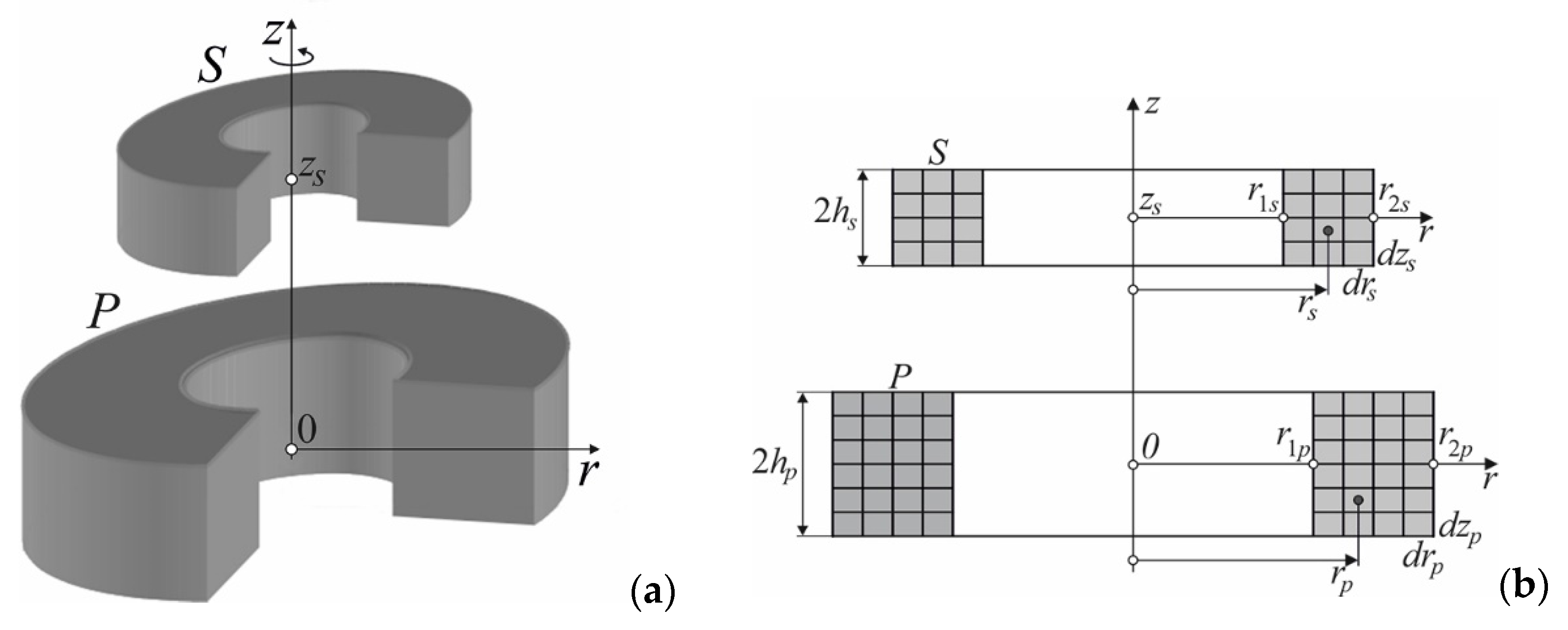
Figure 1. Two coaxial cylindrical coils: general view (a); dimensions and discretization of the primary and secondary coil (b).
Energies 17 00325 g001
Figure 2. Two infinitesimally thin coaxial current loops.
Energies 17 00325 g002
Figure 3. Magnetic field of two coaxial cylindrical coils: both coils powered (a); only primary coil powered (b); only secondary coil powered (c).
Energies 17 00325 g003
Figure 4. Mutual inductance of two coaxial cylindrical coils and its derivative as a function of z-displacement.
Energies 17 00325 g004
Figure 5. Non-coaxial cylindrical coils: general view (a); model for calculating the magnetic flux linking the secondary coil (b).
Energies 17 00325 g005
Figure 6. The initial position of the secondary coil and its three final positions (a); mutual inductance and its derivative of non-coaxial cylindrical coils as a function of displacement in generalized coordinates (b).
Energies 17 00325 g006
Figure 7. Cylindrical coils in any mutual position (with angular and lateral misalignment): general view (a); model for the magnetic flux linkage calculations (b).
Energies 17 00325 g007
Figure 8. Cylindrical coils in any mutual position (two positions of the secondary coil are marked) (a); mutual inductance and its derivative as a function of displacement in r-direction (b).
Energies 17 00325 g008
Figure 9. Two rectangular coils with angular and lateral misalignment (a); dimensions of the primary coil (b).
Energies 17 00325 g009
Figure 10. Dimensions and discretization of the rectangular primary and secondary coils.
Energies 17 00325 g010
Figure 11. Computational model of an infinitely thin band conductor with the current sheet J (a); the elementary rectangular current loop of the primary coil from Figure 10 generating a magnetic field of value H at a point P(x,y,z) (b).
Energies 17 00325 g011
Figure 12. Mutual inductance of rectangular coils and its derivative as a function of x-displacement for parallel and inclined coils.
Energies 17 00325 g012
Figure 13. Distribution of the normal component of the magnetic induction vector (normalized values) over circular and rectangular coils: for current sheet (a,b); for coils of finite thickness (c,d); for coils carrying electric current throughout the entire volume (e,f).
Energies 17 00325 g013
Figure 14. System of permanent magnets exciting a magnetic field in a superconducting levitation system without degrees of freedom (a); normal component of the magnetic induction vector at a distance of 2 mm from the surface of the magnets (b) and at a distance of 5 mm (c).
Energies 17 00325 g014
Figure 15. A linear actuator system consisting of three primary coils and one secondary coil moving at speed v due to forces acting between the coils.
Energies 17 00325 g015
Disclaimer/Publisher’s Note: The statements, opinions and data contained in all publications are solely those of the individual author(s) and contributor(s) and not of MDPI and/or the editor(s). MDPI and/or the editor(s) disclaim responsibility for any injury to people or property resulting from any ideas, methods, instructions or products referred to in the content.