Abstract
This paper investigates the possibilities of limiting emergency short current pulses by using materials with a positive temperature coefficient. A computational model and method for simulating this process were proposed. Barium titanate was considered a promising material for current-limiting devices due to its low cost, ease of manufacturing and autonomy. The current-limiting properties of a PTC thermistor device were estimated in relation to a significant pulse current overload (10 ms). The value of taking into account the varistor effect when modeling energy dissipation by a PTC thermistor is experimentally demonstrated. The results of the experiment were used in the development of computer models of the current-limiting properties of PTC thermistors. A method for taking into account the varistor effect in the developed models is proposed. It is noted that in order to increase the accuracy of the calculation, it is important to take into account the heat transfer between the PTC thermistor and its contact system. It is also shown that this heat transfer is capable of creating a significant longitudinal temperature gradient inside the PTC thermistor, which creates a high level of thermal stress and leads to mechanical failure. Destruction of this type has been observed during experiments. This research was carried out within the state assignment FSEG-2023-0012.
1. Introduction
The problem of short-circuit current limitation occurs everywhere and in many electrical complexes, regardless of the type of current and voltage values [1,2,3]. The cause of this problem is the desire to concentrate generating capacities for various reasons: rapid development of the energy complex of large metropolises, construction of mining complexes removed from the unified energy system (including oil extraction platforms), large underwater and surface vessels, etc. Mechanical circuit breakers often face the problem of insufficient switching capacity and long break times during accidents. In the following, various technical solutions used to disconnect or limit fault short-circuit currents will be discussed in summary.
A classic solution to the problem of current limiting is the use of current-limiting reactors. This technology is widely used due to low production costs and ease of application. Passive reactors do not have any controls and are constantly connected to the protected circuit, which causes large power losses. To solve this problem, twin reactors [4], magnetization-controlled reactors [5], and transformer-type reactors [6] are applied. However, none of this solves the problem of large weight–size parameters [7].
Current-limiting fuses are characterized by simple design and, consequently, relatively low cost. However, they have a number of significant drawbacks: no recoverability; unstable current time characteristics; insufficient operational reliability; limited range of use in terms of rated currents and voltages; lack of control from external devices, in particular, from relay protection devices; and difficulty in carrying out the reclosing cycle of the protected circuit [8].
There are a large number of circuit solutions for current limiting based on semiconductor devices [9,10,11,12,13,14,15]. This type of device is favorably distinguished by the flexibility of application and relatively satisfactory weight–size parameters. One of the disadvantages is the high cost of the semiconductor devices used, as well as their restrictions on the maximum current and voltage withstand.
From the point of view of the current-limiting function, the materials that are able to significantly increase their own electrical resistance under the influence of short-circuit current (magnetic field, electrodynamic action, heating from current, etc.) seem advantageous. The most well-known in this regard are superconducting fault current limiters (SFCLs), which rely on the phenomenon of high-temperature superconductivity. The proliferation of such current-limiting devices is restricted by several factors. Firstly, the first- and second-generation materials used for SFCLs are multi-composite ceramics, which are difficult to produce. In addition, superconducting wires themselves are high-tech products containing a multi-component matrix structure (first generation) or a structure with a large number of thin layers (second generation) [16]. Secondly, the SFCLs used in practice are used in conjunction with a refrigeration system that keeps the conductors in their superconductivity state. For this reason, the entire SFCL complex does not have the most satisfactory weight–size parameters [17]. Thirdly, high-temperature superconducting wires have a significant limitation on current density [17].
PTC thermistors are also capable of significantly increasing their active resistance under the influence of heating from the flowing current. In contrast to SFCLs, the chemical formula of their material is much simpler, and the manufacturing technology is less demanding and cheaper. However, for the development of current-limiting devices based on PTC thermistor elements, there is a lack of experimental data confirming the ability to withstand and limit a significant current impulse. There is also the need to develop an accurate mathematical model of such a device. This will make it possible to design one for higher voltages and currents.
The rest of the article presents an overview of the materials used in electrical engineering with a positive temperature coefficient, the temperature-dependent characteristics of barium titanate, an electrical diagram and description of the bench for generating an industrial frequency current pulse, an algorithm for implementing the thermal model of a PTC thermistor in MATLAB Simulink 2020b, a MATLAB Simulink model of the test bench, the results of simulation and experiments (oscillograms of current, voltage, etc.), the photos of PTC thermistors destroyed under the impact of the current pulse, and the simulation results of an experiment in COMSOL Multiphysics 6.1 (diagrams of temperature fields after exposure to current impulses).
2. PTC Thermistors
PTC thermistors are devices made on the basis of a material that increases its electrical resistance when the temperature of this material increases. In particular, PTC thermistors are often viewed as devices capable of increasing their electrical resistance by several orders of magnitude in a limited temperature range (phase transition of material properties). Due to this property, PTC thermistors are widely used as current-limiting devices in various circuits of electrical appliances and electrical equipment.
The materials used as the basis of the PTC thermistor can be divided into four groups [18]:
- PTC thermistors based on polymer composites [19,20];
- PTC thermistors based on ceramic composites [21,22];
- PTC thermistors based on vanadium (III) oxide [23,24,25];
- PTC thermistors based on barium titanate [26,27,28,29].
The last member of this list is the easiest and cheapest to produce. Consequently, barium titanate PTC thermistors have become more widely used in practical applications. This also provided the basis for the fact that this group of PTC thermistors is the most studied. In particular, the temperature dependencies of their various mechanical and physical properties are well-known. Based on all the above, this group of PTC thermistors was chosen for theoretical, numerical and experimental study of current-limiting properties relative to the impact of current pulses.
Other materials under review have a number of unique properties. The presence of these properties is of interest for similar future studies.
2.1. Barium Titanate
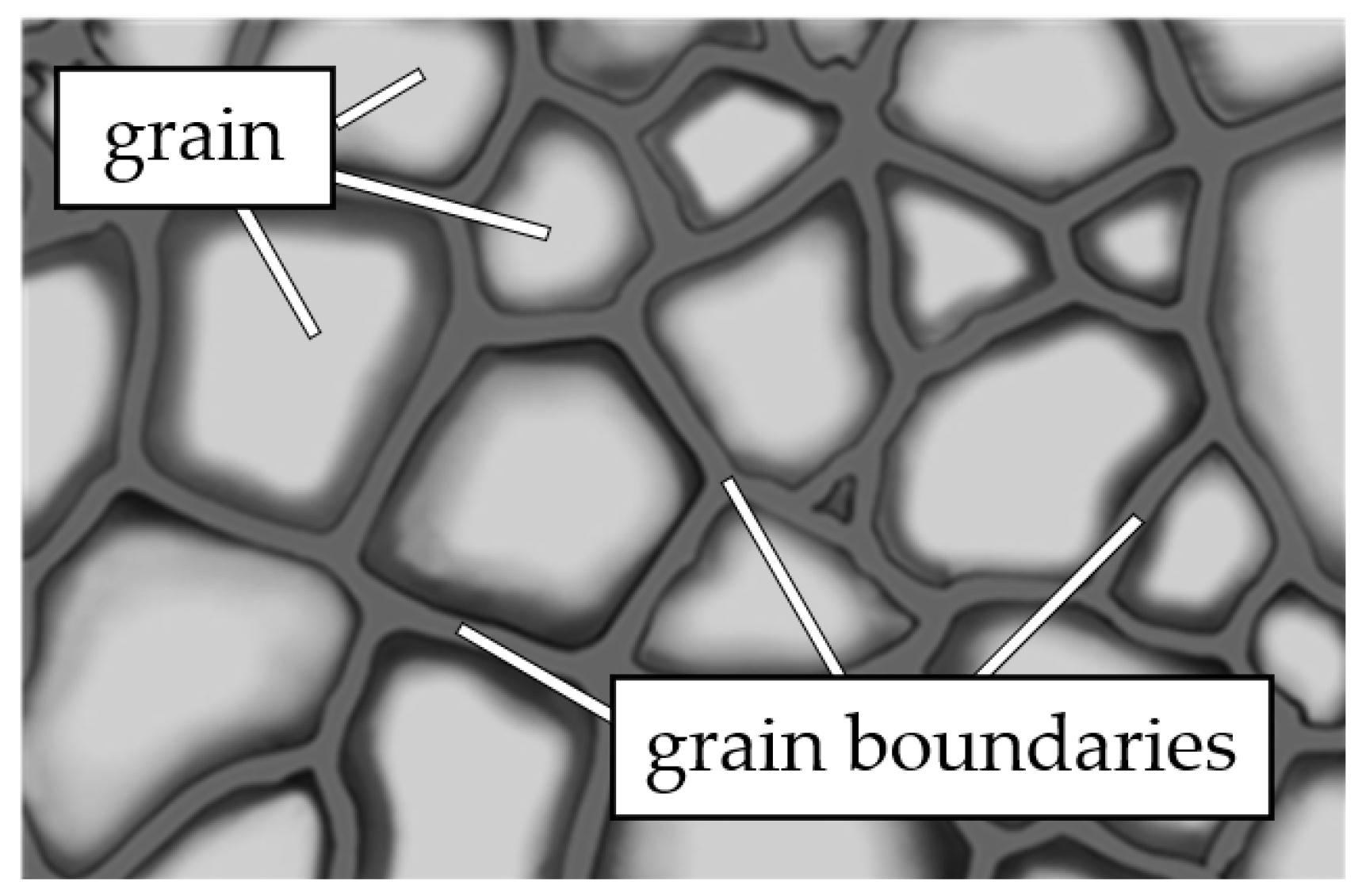
The resistive layer of a PTC thermistor consists of a large number of contacting grains of semiconductor barium titanate, as shown in Figure 1.

Figure 1.
Schematic representation of the grain structure of barium titanate (narrow dark bands represent grain boundaries; light areas of the images represent the grains themselves).
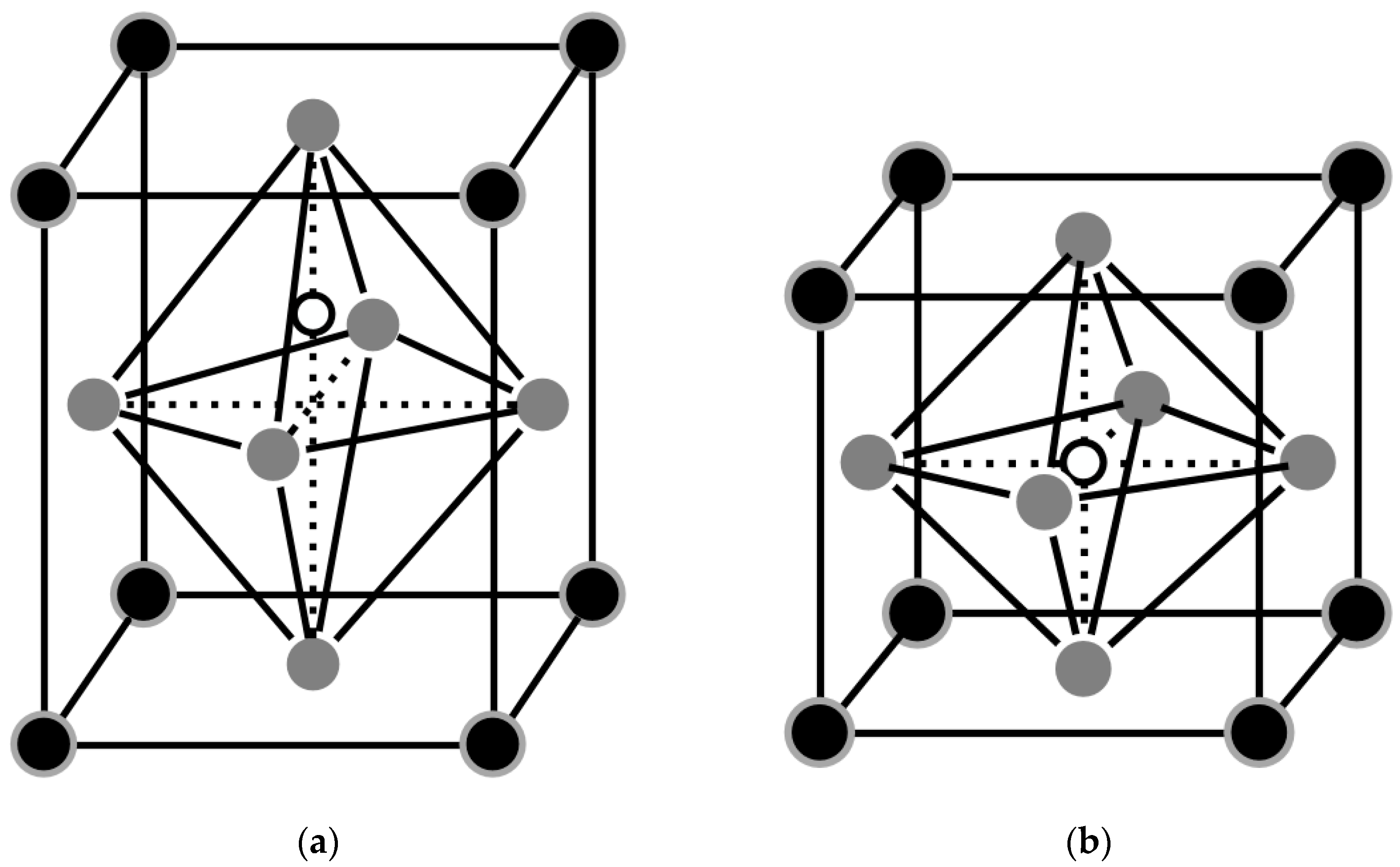
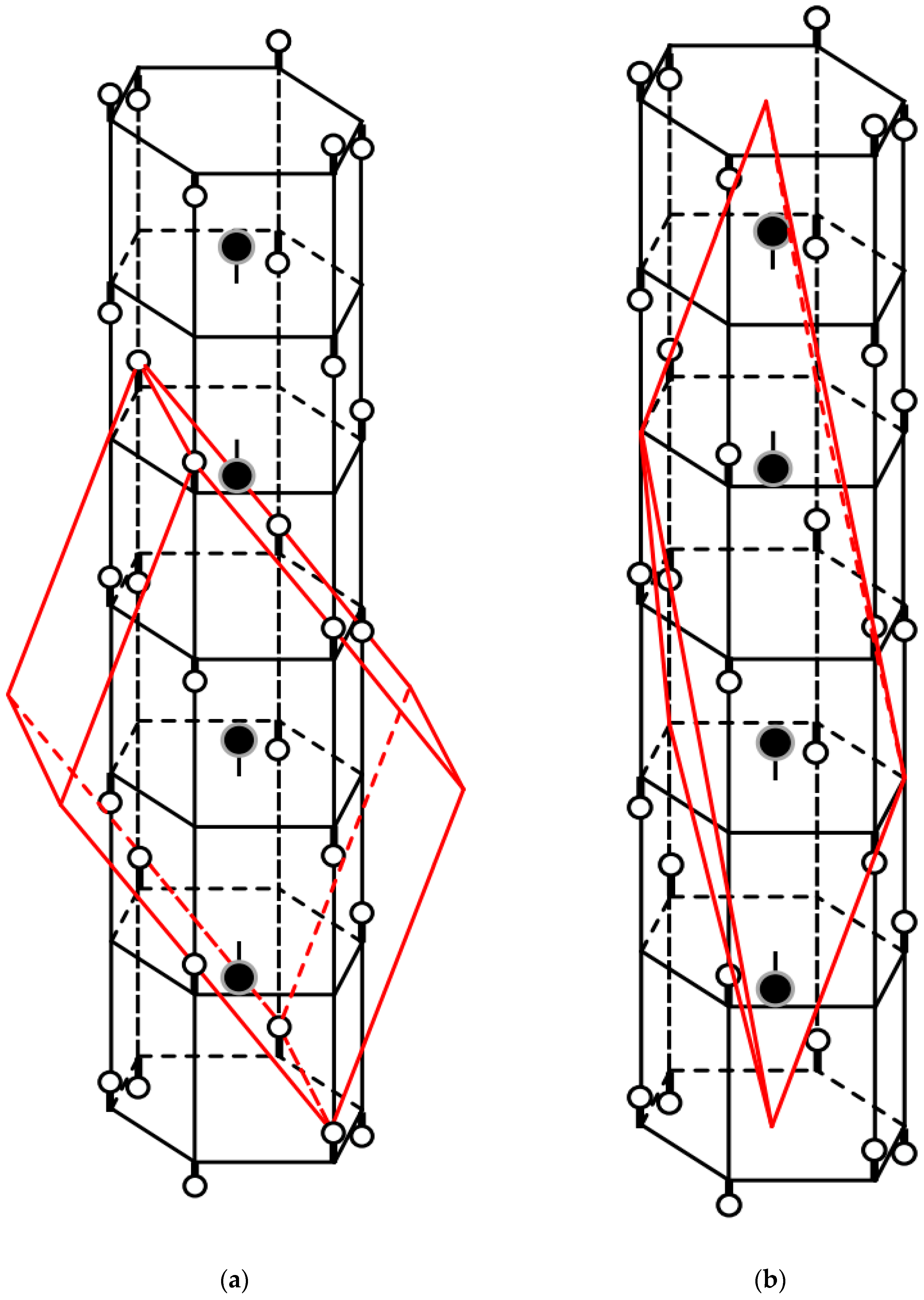
At room temperature (below Curie temperature (TC)), the crystal structure of barium titanate consists of tetragonal cells. Such a cell is shown in Figure 2a. Black knots of the lattice represent barium atoms Ba+2, gray nodes represent oxygen atoms O−2, and white nodes represent atoms of titanium Ti+4.

Figure 2.
Crystal structure of BaTiO3. (a)—tetragonal cell shape (the temperature of the structure is less than TC); (b)—perovskite cell shape (the temperature of the structure is greater than TC).
As can be seen from the figure, the crystal structure of the barium titanate is asymmetrical, and the titanium atom is displaced from the center of the tetragonal cell. This determines the presence of a dipole moment and spontaneous polarization in the entire structure. At present, the material has a very high permittivity. The height of the surface potential barriers at the grain boundary is low. PTC thermistors’ resistance is determined by the resistance of depleted surface layers at the grain boundaries [30].
The impurity-free semiconductor BaTiO3 is a dielectric. To use it as a current-limiting element, impurity ions are introduced into it. As a result, a large number of donor and acceptor levels are created in the grain boundary zones. Consequently, such crystals (similarly to extrinsic semiconductors) have high conductivity, increasing their conductivity by a factor of 104 to 108 [31]. For barium titanate, La, Sb, Zn, Sn, Ce, Zr and Hf are used as doping agents [32]. The use of other impurities, such as Fe, Mn, V, Cr, Ni and Co, on the contrary, can significantly (up to 104 times) increase the resistance of the PTC thermistor above the Curie point while also increasing the resistance below the Curie point (at room temperature). Also, in particular, with the help of Fe or Mn additives, the phase transition temperature can be controlled [33].
When the temperature of the PTC thermistor reaches the Curie point, the tetragonal shape of the cell changes to a fully symmetrical, perovskite form (as shown in Figure 2b) and loses the dipole moment. At the same time, spontaneous polarization disappears, the permittivity decreases sharply, the height of potential barriers on the grains increases, and the resistance of the PTC thermistor rises. The previously mentioned ceramic composites have similar properties and mechanisms of action since their composition is dominated by barium titanate or other composites based on similar perovskite structures. For example, these include SrTiO3 with the addition of niobium, lanthanum, lead titanate, and a number of others.
2.2. Vanadium (III) Oxide
Prior to the phase transition temperature, the structure of the V2O3 cell is monoclinic, as shown in Figure 3a. At temperatures above the Curie point, the transition from a monoclinic to a rhombohedral lattice occurs, as shown on the right in Figure 3. The dark circles denote vanadium atoms, and the light circles denote oxygen atoms. As the temperature increases, the distance between adjacent vanadium atoms grows, while the average distance between vanadium atoms and oxygen atoms, as a whole, remains unchanged [34]. At the same time, the change in electrical resistance can be explained by the Mott transition model for charge carriers [35]; however, the true microscopic interpretation of the Mott model for the metal–dielectric phase transition is still lacking [36,37].
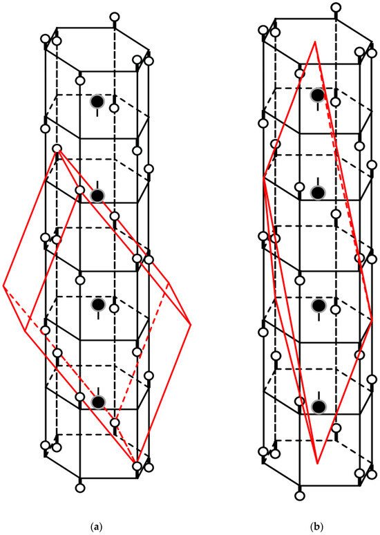
Figure 3.
Crystal structure of the V2O3. (a) Monoclinic cell shape (red lines; the temperature of the structure is less than TK); (b) rhombohedral cell shape (red lines; the temperature of the structure is greater than TK).
The application of the properties of vanadium (III) oxide for the purpose of current limitation is a very promising task. Chromium doping can significantly reduce the resistance of the vanadium (III) oxide at room temperature (below the Curie point), making it several orders of magnitude lower than that of barium titanate PTC thermistors [23,38]. This will allow the use of vanadium (III) oxide-based PTC thermistors in high-current circuits. However, there are a few limitations to this. First, during the phase transition, the volume of unit cells of V2O3 changes by 0.8–3.5%, which leads to microcracks in the PTC thermistor and, in turn, to the destruction of materials of arbitrary shape during multiple phase transitions [39]. Secondly, the technology for producing vanadium (III) oxide is more complex than that of barium titanate, which leads to an increase in the cost of production of such a PTC thermistor.
The physical properties of vanadium (III) oxide are well studied. In the future, this aspect will make it possible to reproduce computer models of current-limiting devices based on this material with good accuracy.
Vanadium (III) oxide has unique current-limiting properties. However, the lack of experimental data on the effect of current pulses on PTC thermistors based on V2O3 calls for additional study of this material.
2.3. Polyswitch
The mechanism of the operation of polymer PTC thermistors is as follows. The devices are made of a crystalline polymer that includes conductive particles distributed in the volume of the element. At normal device temperatures, these particles create a conductive grid due to their contact with each other in the polymer. However, if the temperature rises to a point where the polymer crystallites melt and become amorphous, the device switches. The increase in volume during the melting of the crystalline polymer particles causes a break in the conductive chains and, as a result, a sharp nonlinear change in the resistance of the entire device [19]. We should note that such a transition is reversible and can occur repeatedly.
3. Dynamic Characteristics of Barium Titanate
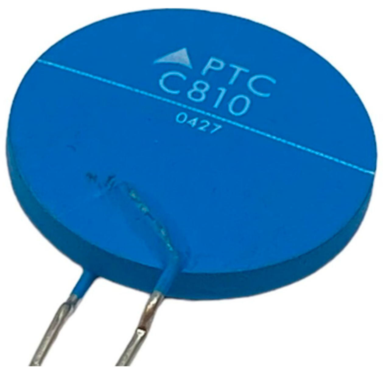
For the experiments, the B59810-C120-A70 PTC thermistor manufactured by EPCOS AG (Munich, Germany) was used (its appearance is shown in Figure 4). The basis of the material of the studied samples is BaTiO3.

Figure 4.
Test specimen: PTC thermistor B59810-C120-A70.
Specimen thickness: 3.42 mm. Specimen diameter: 25.2 mm. Average specimen weight: 8.091 g.
In the remainder of this section, the various heat-dependent characteristics of barium titanate that have been taken into account in the computer simulations will be presented.
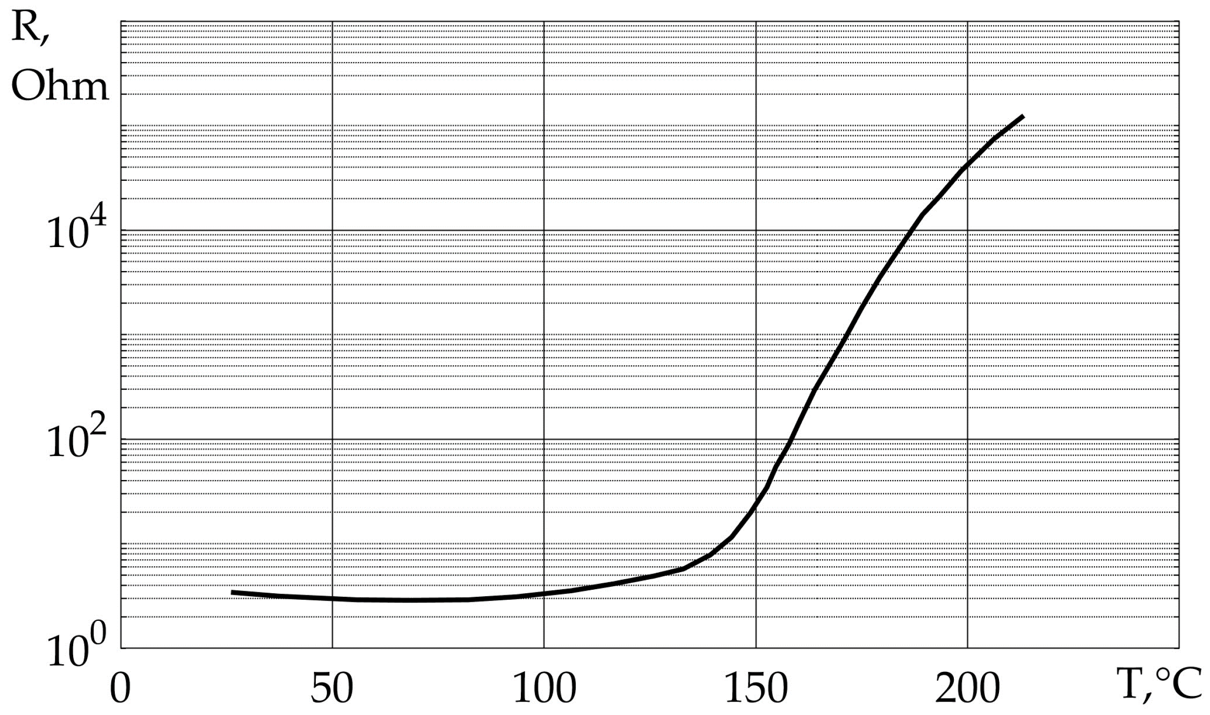
3.1. Characteristic R(T)
For the computer model of PTC thermistor substitution, its datasheet dependence R(T) was used, as shown in Figure 5.
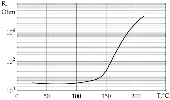
Figure 5.
R(T) characteristic of the PTC thermistor B59810-C120-A70.
This characteristic has been used in PTC thermistor models in Matlab Simulink and Comsol Multiphysics.
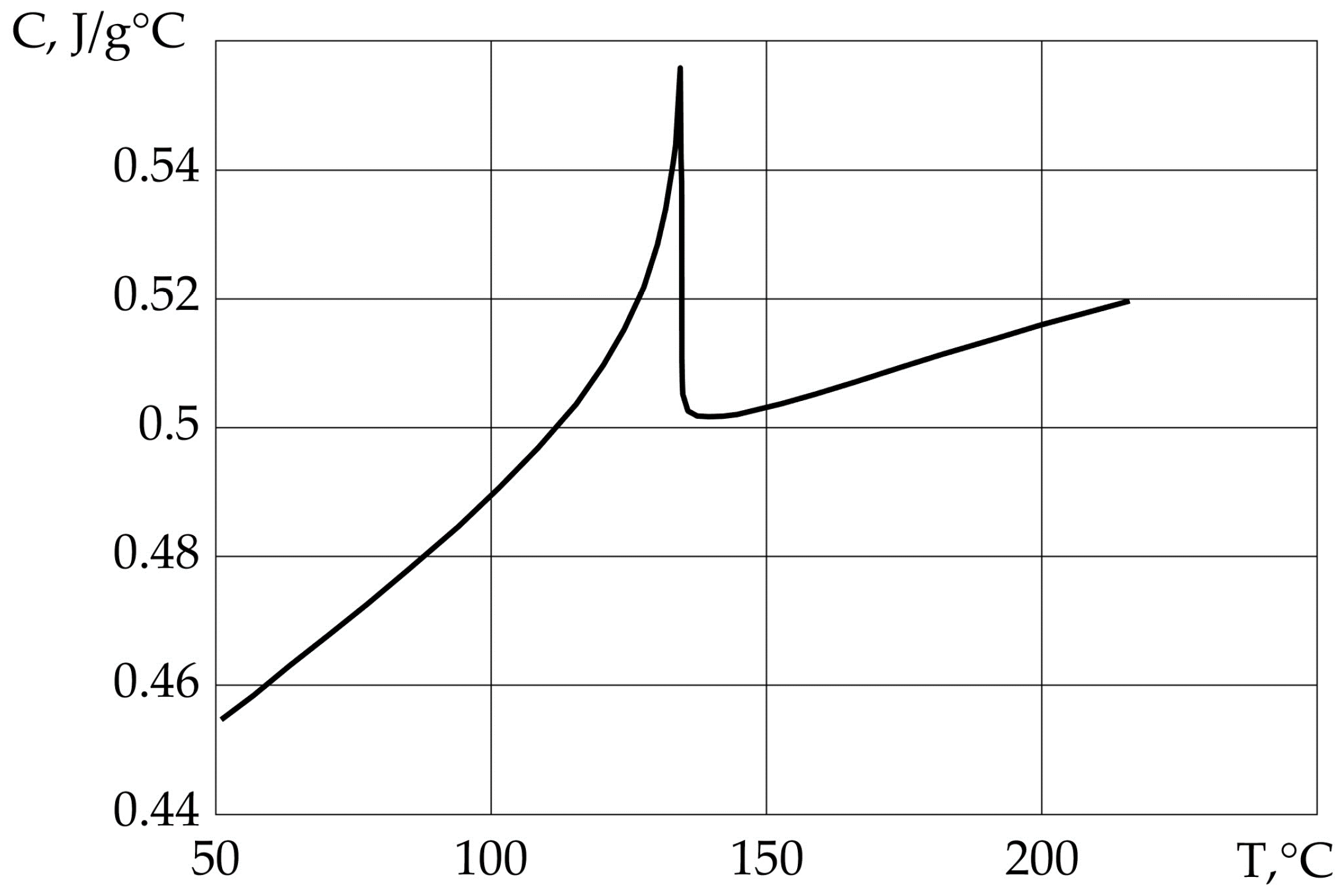
3.2. Characteristic Cp(T)
The dependence of the heat capacity of the PTC thermistor material (Cp(T)) on temperature also undergoes a phase transition of the first kind and has been used in the computer models Matlab Simulink and Comsol Multiphysics. This dependence is shown in Figure 6 [40].
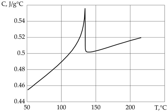
Figure 6.
C p(T) characteristic of barium titanate.
As can be seen from Figure 6, the heat capacity of the PTC thermistor undergoes a one-time change of ~10%. Taking into account this dependence will increase the accuracy of the models under study.
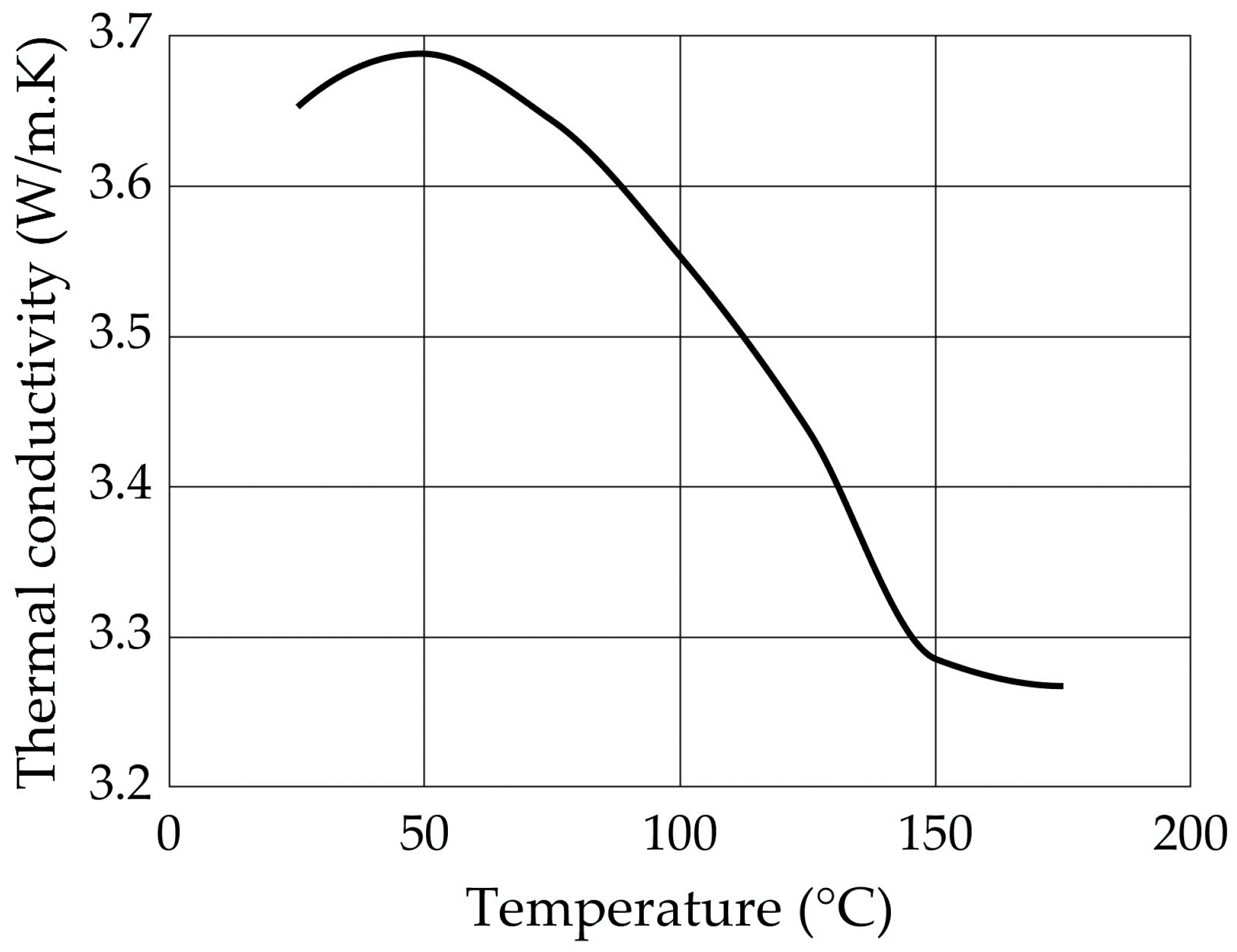
3.3. Thermal Conductivity
In addition, the thermal conductivity dependencies of barium titanate were imported into the Comsol Multiphysics model to increase the accuracy of the calculation. These data were taken from [41] and are shown in Figure 7.
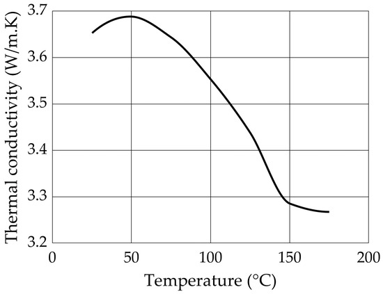
Figure 7.
Temperature dependence of thermal conductivity of barium titanate.
3.4. Varistor Effect
Similarly to a varistor, depending on the strength of the electric field, the resistance of the PTC thermistor can decrease slightly as the strength of the electric field increases [42]. This varistor effect is observed in the R(T) characteristic over the entire temperature range under study.
To account for the varistor effect, the following dependency will be introduced into the Matlab Simulink model:
where R’(V,T) is the electrical resistance of the PTC thermistor sample under study, depending on its temperature and the voltage applied to it; V is the voltage applied to the test specimen; and Vvar is the coefficient that describes the varistor effect in the model.
R’(V,T) = R(T) · (1 − V/Vvar),
A similar dependency has been introduced for the Comsol Multiphysics model:
where G’(V,T) is the specific electrical conductivity of the PTC thermistor sample under study, which depends on its temperature and electric field strength; E is the electric field strength; and Evar is the coefficient that describes the varistor effect in the model.
G’(V,T) = G(T) · (1 + E/Evar),
3.5. Characteristic εp(T)
In order to correctly interpret the expression (2), the thermal dependence of the barium titanate dielectric constant εp(T) must be taken into account in the Comsol Multiphysics model. This relationship was taken from [43] and is shown in Figure 8.
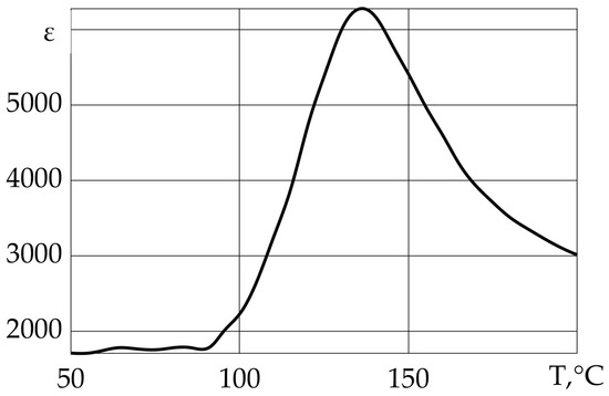
Figure 8.
εp(T) characteristic of barium titanate.
4. Research Methodology
4.1. Test Bench
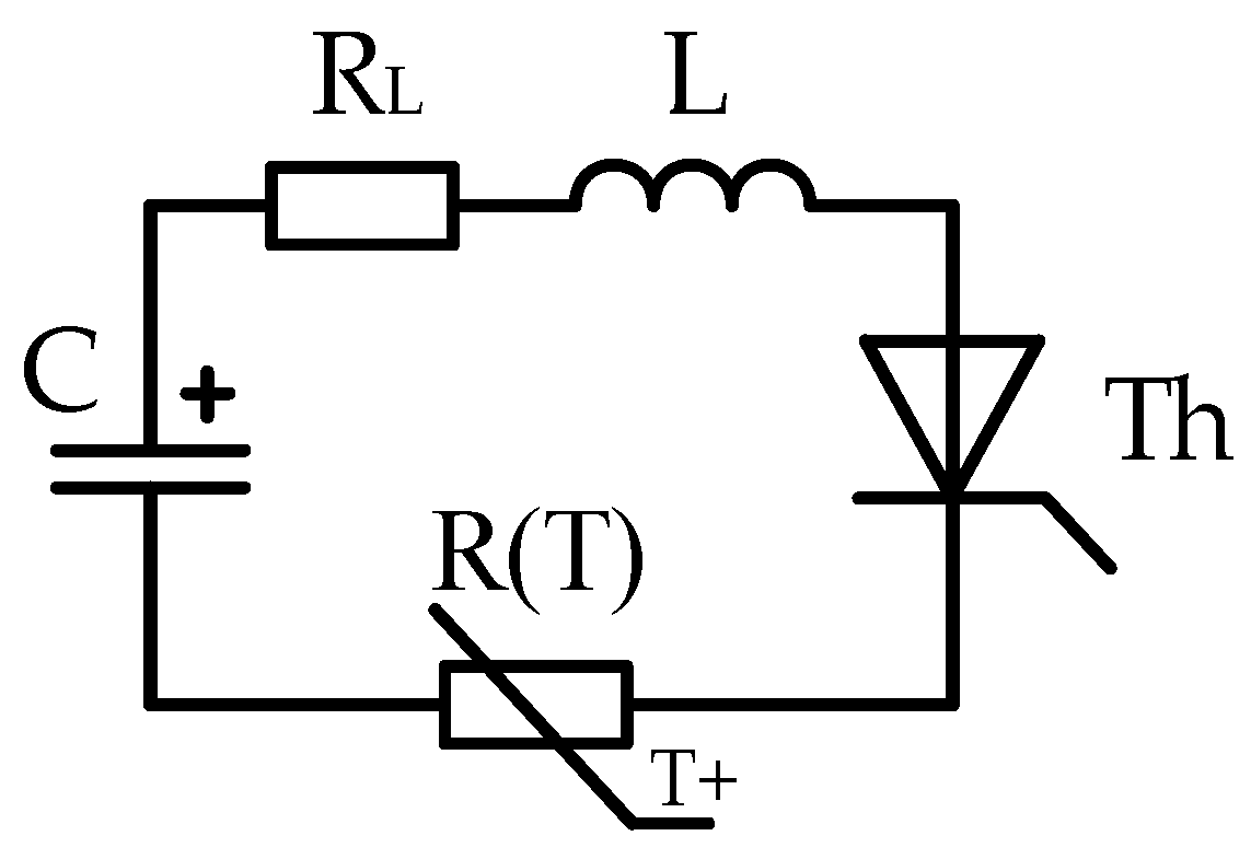
To test the PTC thermistor for the current-limiting capacity in short current pulses, a test bench was assembled, the electrical circuit of which is shown in Figure 9.

Figure 9.
Electrical circuit of the test bench.
This circuit has the following electrical parameters: capacitance of the battery C = 5.64 mF; reactor inductance L = 3.5 mH; and active resistance of the reactor winding RL = 0.4 Ohm. The initialization of the battery discharge was carried out using a thyristor. Current measurements were made using a Hall sensor. The voltage on the PTC thermistor was also measured during the experiments.
The experiment of overloading the PTC thermistor with a current pulse was carried out as follows: 1. The capacitor battery is charged to a certain voltage value (in the range of 200–400 V). 2. The PTC thermistor is heated by an industrial hot air blower to a temperature slightly above 90 °C. 3. When the PTC thermistor naturally cools down to a temperature of 90 °C, a signal to discharge the capacitor battery is provided. 4. With the help of an infrared pyrometer, the temperature of the PTC thermistor after the current pulse is measured. An oscillogram of current and voltage on the PTC thermistor is recorded.
The preheating temperature (T0 = 90 °C) was chosen as the point close to the least resistance and close to the phase transition temperature (Figure 5), which would allow the largest current pulse to pass through the sample, which in turn would allow the observation of the more pronounced current-limiting properties.
The results of the experiment and their description are provided in Section 5 of this article, together with the results of the computer simulations from Section 4.2 and Section 4.3 of this paper.
4.2. Comsol Multiphysics Computer Model
Electric currents, heat transfer in solids and electrical circuit modules were used to simulate the heating of the PTC thermistor through the transmitted current pulse. Figure 10 shows the geometry of the model.
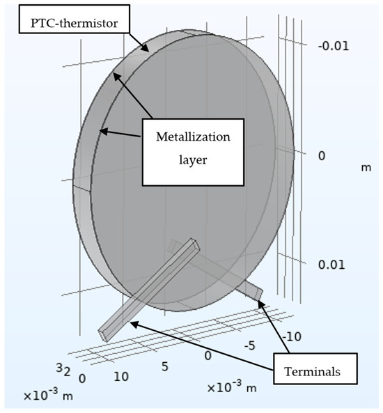
Figure 10.
PTC thermistor model in Comsol Multiphysics (Figure 4).
Geometric parameters of the model: thickness of the PTC thermistor material is 3 mm; thickness of the metallization layer is 0.1 mm; contact length (with the metallization layer) is 8 mm; contact height is 0.6 mm; and contact width is 1.1 mm.
The heat dissipation from the surface of the sample was not taken into account since, during the transient process (the duration of the current pulse of 10–20 ms), it is considered insignificant. Heat dissipation occurs only due to the thermal conductivity of the contact system. In the electrical circuits module, a circuit similar to the one pictured in Figure 9 was constructed.
4.3. Matlab Simulink Computer Model
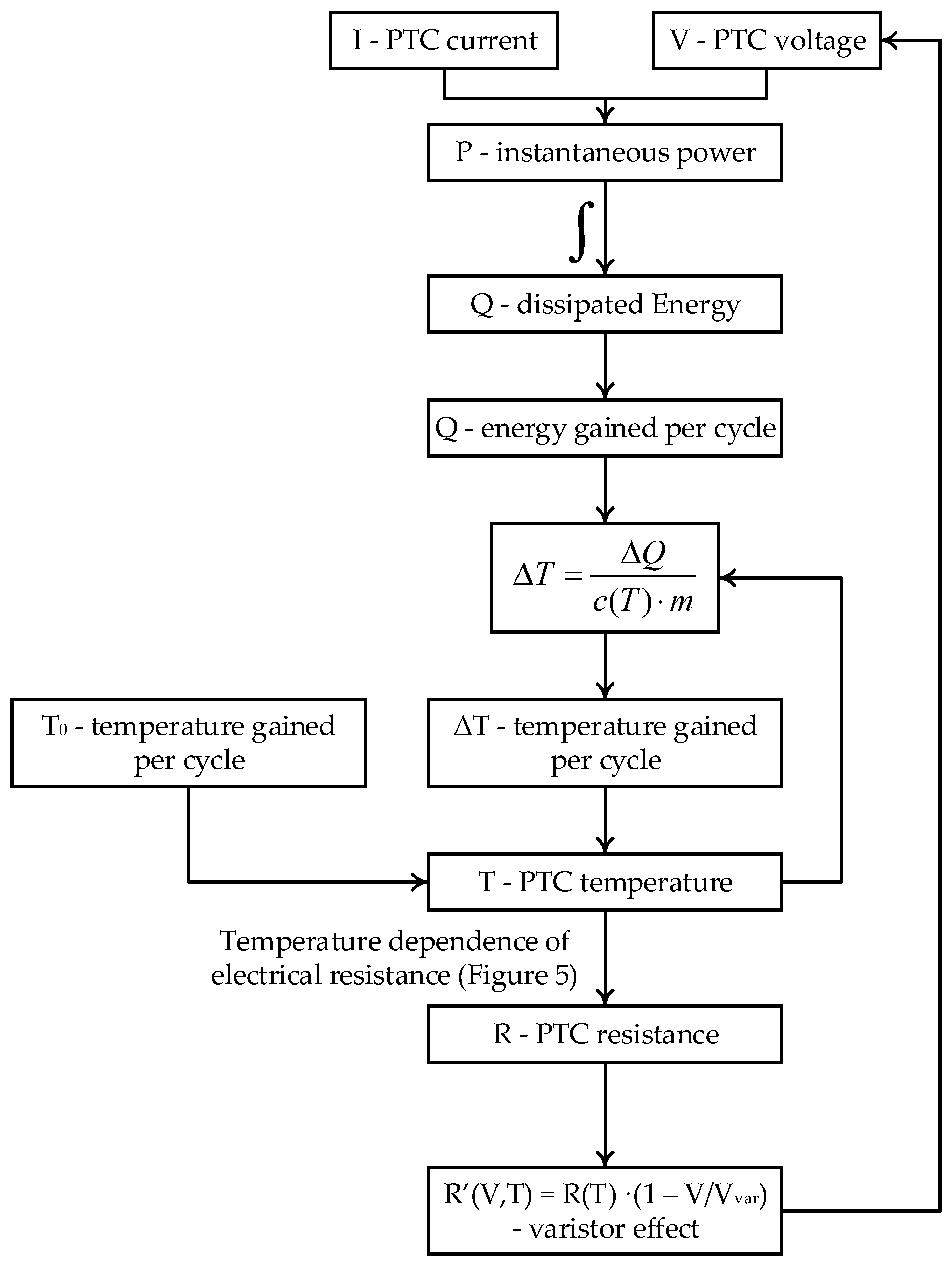
In principle, the diagram implemented in MATLAB Simulink does not differ from the one shown in Figure 9. The PTC thermistor is implemented in the circuit as a voltage source controlled by the algorithm shown in Figure 11. Heat dissipation was also not taken into account in this model for the same reasons. The distribution of current density and temperature is considered to be uniform, which is due to the positive temperature coefficient of the material.
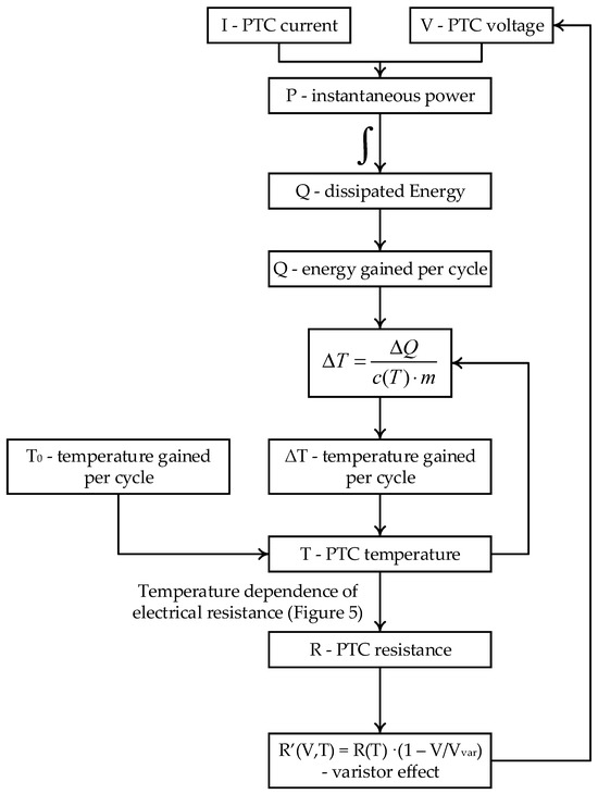
Figure 11.
Flow diagram of the PTC thermistor implementation.
Transition in the flowchart in Figure 11, “Temperature dependence of electrical resistance”, was taken from Figure 5. In the block diagram, m is the mass of the PTC thermistor, and c(T) is the heat capacity of the PTC thermistor. As described earlier, many characteristics undergo changes during the phase transition.
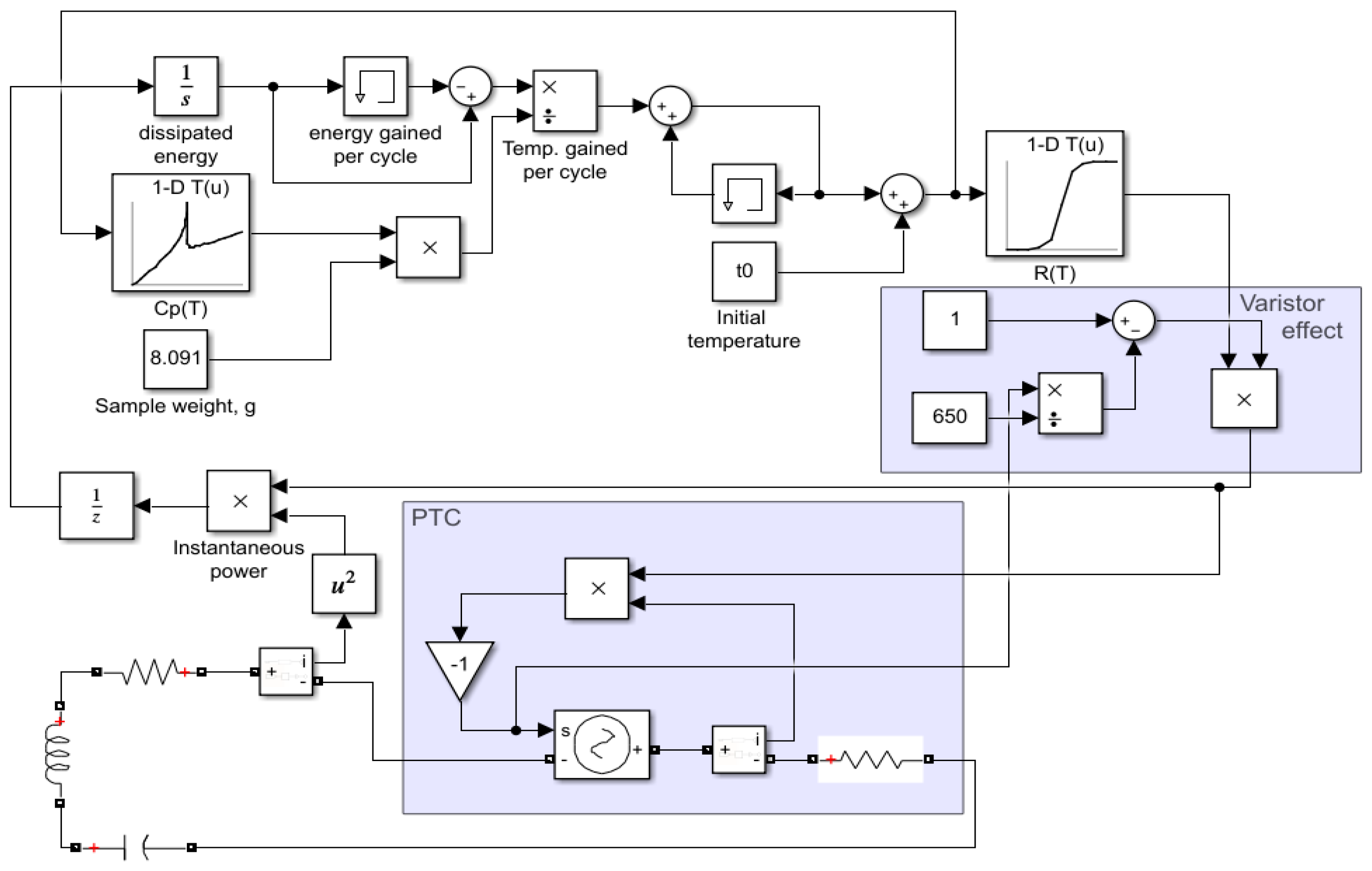
Figure 12 shows the MATLAB Simulink model, which was used to simulate the operation of the test bench.
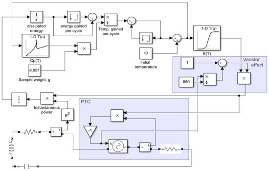
Figure 12.
MATLAB Simulink test bench model.
The results of the simulation and their description are provided in Section 5 of the paper, together with the results of the experiment described in Section 4.1.
5. Analysis of Research Results
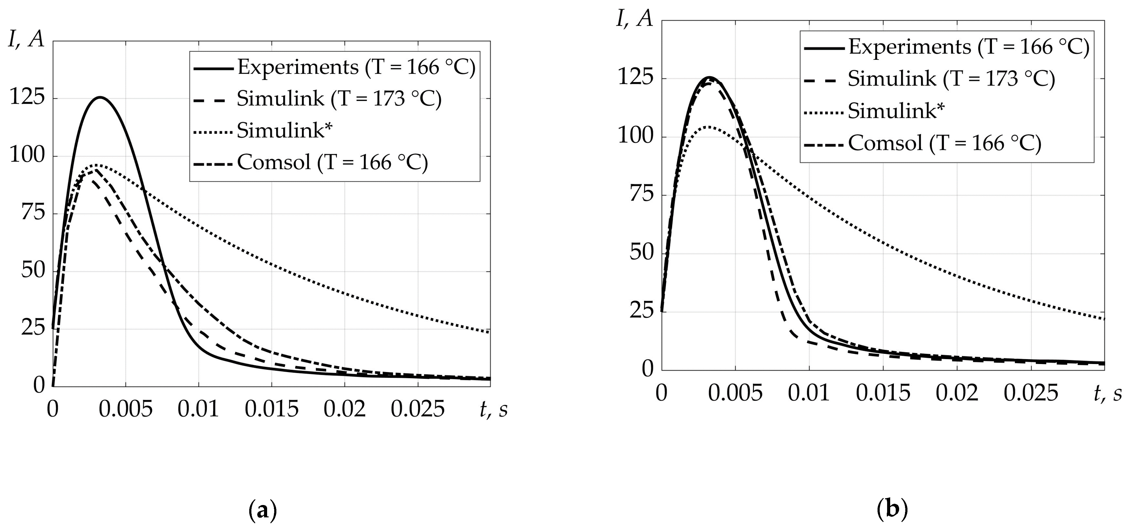
Figure 13 shows the results listed in Section 4. The current curves from the Comsol Multiphysics and Matlab Simulink models pictured in Figure 13a were obtained without taking into account the varistor effect. Figure 13b contains the results of the models accounting for the varistor effect. The curve denoted Simulink* (with a constant resistance corresponding to the initial heating temperature) was added to demonstrate current-limiting properties. The voltage of the capacitor battery is 374 V. The initial heating temperature of the PTC thermistor is 90 °C. The Vvar and Evar coefficients for expressions (1) and (2) were chosen as 650 and 3 × 10⁵, respectively;

Figure 13.
PTC thermistor current. (a) Modeling without taking into account the varistor effect; (b) modeling with regard to the varistor effect. Solid curves are results of the experiment; dashed curves are Matlab Simulink simulation results; dotted curves are results of Matlab Simulink simulations with a constant resistance corresponding to a temperature of 90 °C; dash-dotted curves are Comsol Multiphysics simulation results.
As can be seen from Figure 13, taking into account the varistor effect allows for a fairly accurate simulation of the current-limiting properties of a PTC thermistor. It can also be concluded that the heat dissipation through the contact system has to be taken into account, as the Comsol model clearly demonstrates. Analysis of the heat-dependent parameters of barium titanate showed that changes in thermal conductivity and heat capacitances are negligible in terms of impact on the simulation results.
Additional simulation results and their processing are shown in Figure 14. A curve labeled Dissipated energy* (with constant resistance) has been added to demonstrate the efficiency of energy dissipation via a PTC thermistor.
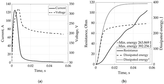
Figure 14.
Experimental results and their processing. (a) PTC thermistor current and voltage; (b) oscillograms of resistance and dissipated energy changes (*—curve with a constant resistance corresponding to the initial heating temperature).
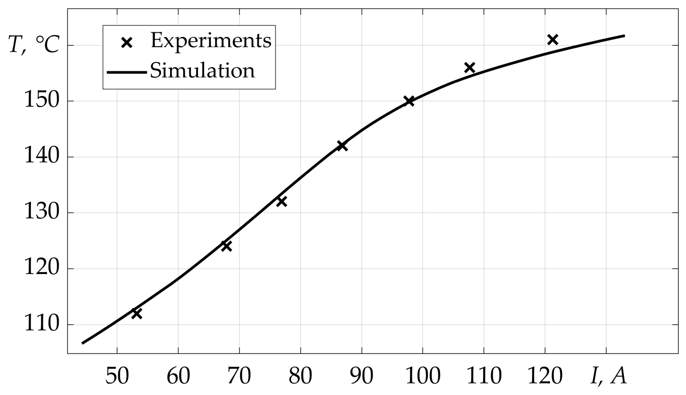
Figure 15 shows the change in the temperature of the PTC thermistor depending on the maximum current pulse passed through it. During modeling and experiments, the initial temperature of the PTC thermistor was 90 °C.
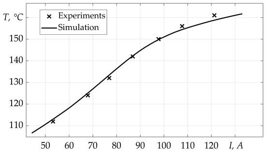
Figure 15.
Dependence of the PTC thermistor temperature on the maximum current pulse passed through it. Experimental and simulation results.
6. Fracture Mechanism
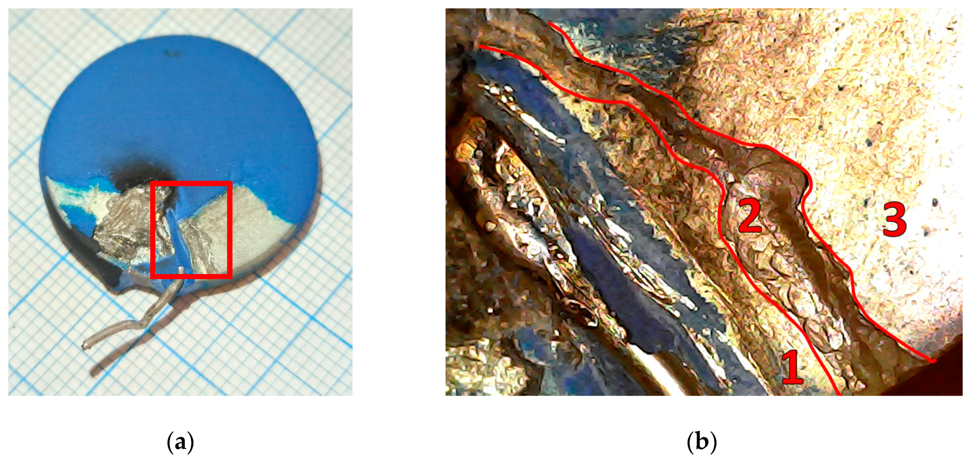
When the voltage of the capacitor battery was increased above ~380 V, the PTC thermistors with a variable resistance of the specimen (from ~3 ohms to ~30–40 ohms at 25 °C) were damaged. Photos of the damaged PTC thermistor are shown in Figure 16.

Figure 16.
Destruction of the PTC thermistor. (a) A photograph of the damaged PTC thermistor (the highlighted red area is shown in more detail in figure (b)); (b) the damaged area enlarged (zone 2—damaged metallization layer on the surface of the PTC thermistor; zones 1 and 3—areas without damage).
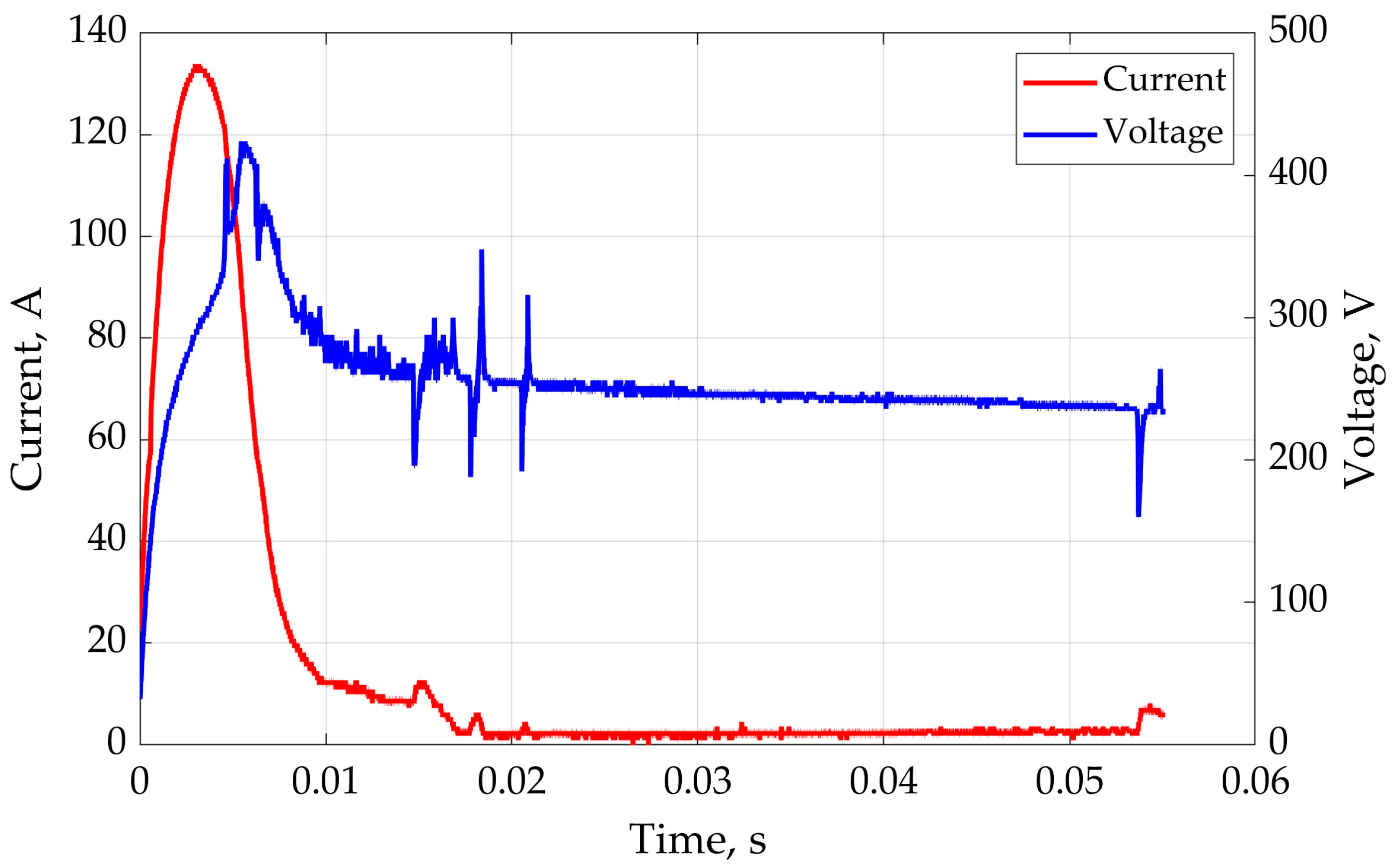
Electrical resistance was measured at different points of the sample surface. The measurements showed the following (Figure 16b): when measuring the active resistance between zone “1” and the electrode on the back side of the PTC thermistor, the device showed a resistance of R ≈ 35 ohms. When measuring the resistance between the zone “3” and the electrode on the reverse side, the ohmmeter showed a resistance of R ≈ 3 ohms. From this, we can conclude that the permanent change in the resistance of the PTC thermistor after the accident is related to the damage to the surface layer of metallization in section “2” of the PTC thermistor surface. Figure 17 shows current and voltage waveforms when the test specimen is damaged.

Figure 17.
Oscillogram of current and voltage of a PTC thermistor during its destruction.
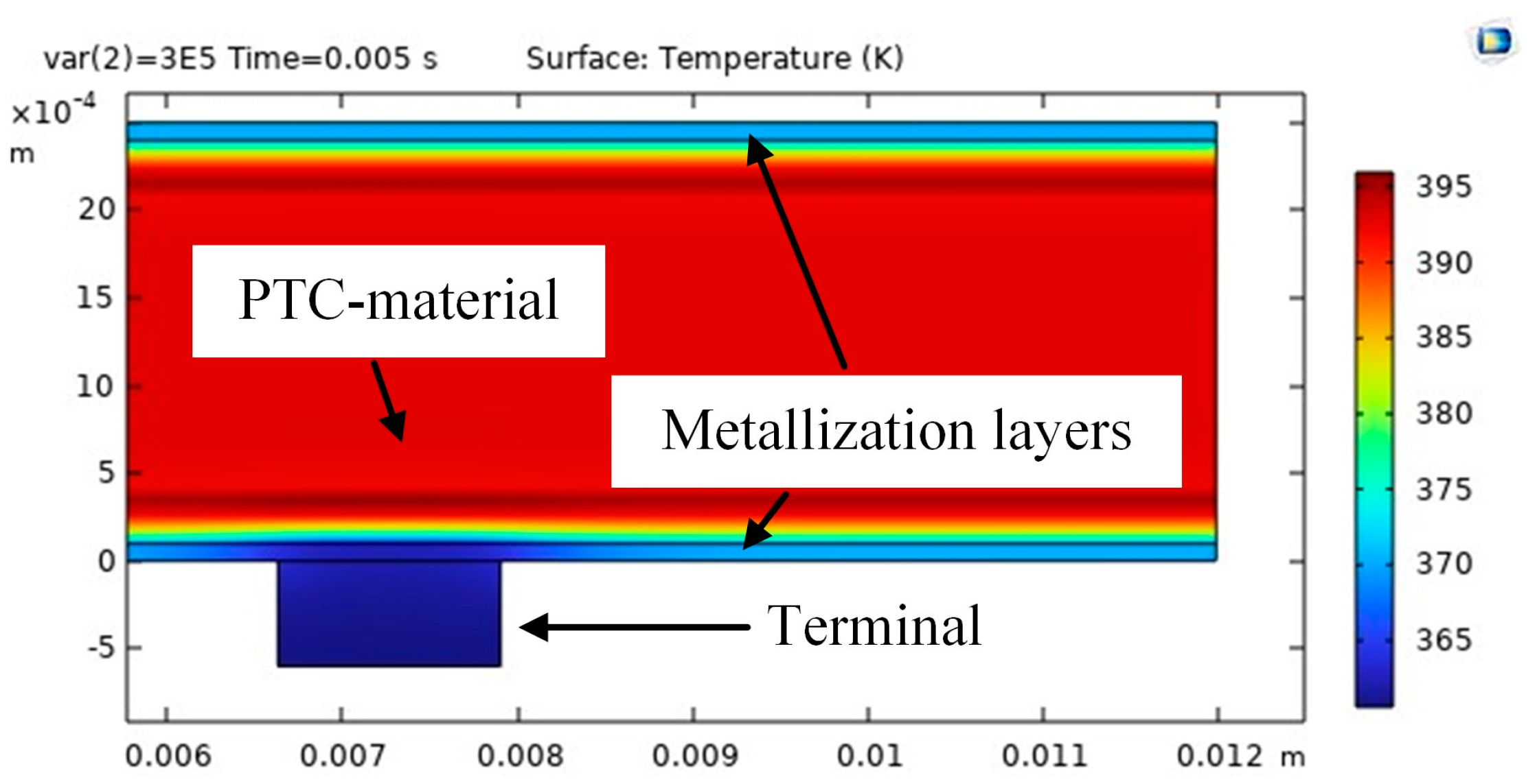
The probable scenario for the development of the accident is as follows. Joule heating of the PTC thermistor material resulted in a significant temperature gradient between the metallization surface and the rest of the PTC thermistor. This is known from simulations in Comsol Multiphysics (Figure 18). Due to thermal expansion (caused by the current pulse), the specimen cracked, which partially damaged the metallization layer near the contact area. This is evidenced by the following: first of all, in Figure 16b along zone “2”, a crack in the body of the PTC thermistor material is clearly visible; secondly, in Figure 17, at a time of ~5 ms, there is a current surge due to partial destruction of the metallization layer. Further deterioration of the metallization layer led to repeated arc overlapping of the specimen. This is evidenced by the presence of traces of electric arc burning (Figure 16a) and a voltage surge in the time range of ~0.013–0.022 ms and for 0.05 ms (Figure 17).

Figure 18.
Temperature field inside the PTC thermistor in contact area. Comsol Multiphysics simulation result.
7. Conclusions
The paper analyzes existing materials with PTC thermistor properties and considers the physics of their phase transition and the physical and electrical properties of materials.
Computer models have been developed that make it possible to simulate significant current overloads of PTC thermistor material with good accuracy. A significant influence of the varistor effect on the process of current limitation has been determined. The presented models were verified via experimental data.
The results of simulations and experiments clearly demonstrate the current-limiting properties of PTC thermistor devices.
The mechanism of destruction of PTC thermistor devices at significant current overloads, which was observed in experiments, is explained.
The research was carried out within the state assignment FSEG-2023-0012.
Author Contributions
Conceptualization, V.F.; data curation, E.S. and R.Z.; formal analysis, V.F.; investigation, E.S.; methodology, E.S. and R.Z.; project administration, Y.P.; resources, R.Z.; software, E.S. and R.Z.; supervision, V.F. and Y.P.; writing—original draft, E.S.; writing—review and editing, V.F. All authors have read and agreed to the published version of the manuscript.
Funding
The work was carried out within the research topic of the FSEG-2023-0012 state assignment.
Data Availability Statement
Publicly available datasets were analyzed in this study. This data can be found here: https://drive.google.com/drive/folders/1tK5OhG0kRXi134hOCV3zq66bMI0QwLK-?usp=sharing (accessed on 26 November 2023).
Conflicts of Interest
The authors declare no conflicts of interest.
References
- Vostrov, K.; Frolov, V.; Safonov, E. Development of Current Limiting Device for Short and Autonomous Networks. Plasma Phys. Technol. 2017, 2, 182–185. [Google Scholar] [CrossRef]
- Morton, J.S. Circuit Breaker and Protection Requirements for DC Switchgear Used in Rapid Transit Systems. IEEE Trans. Ind. Appl. 1985, 2, 1268–1273. [Google Scholar] [CrossRef]
- Cairoli, P.; Rodrigues, R.; Raheja, U.; Zhang, Y.; Raciti, L.; Antoniazzi, A. High Current Solid-State Circuit Breaker for Safe, High Efficiency DC Systems in Marine Applications. In Proceedings of the 2020 IEEE Transportation Electrification Conference & Expo (ITEC), Chicago, IL, USA, 23–26 June 2020; pp. 936–941. [Google Scholar] [CrossRef]
- Hamer, P.S. Application of the Duplex Reactor-an Unusual and Forgotten Technique to Reduce Short Circuit Duty. In Proceedings of the Fifty-First Annual Conference 2004 Petroleum and Chemical Industry Technical Conference, San Francisco, CA, USA, 13–15 September 2004; pp. 65–71. [Google Scholar] [CrossRef]
- Bryantsev, A.M.; Bryantsev, M.A.; Dyagileva, S.V.; Karymov, R.R.; Lur’e, A.I.; Makletsova, E.E.; Negryshev, A.A. Regulated Reactive-Power Sources with Biasing-Controlled Shunting Reactors and Capacitor Banks. Russ. Electr. Engin. 2010, 81, 176–182. [Google Scholar] [CrossRef]
- Alexandrov, G.N.; Dardeer, M.M. Long Distance Transmission Line with Controlled Shunt Reactors (CSRT). In Proceedings of the 2008 12th International Middle-East Power System Conference, Aswan, Egypt, 12–15 March 2008; pp. 294–299. [Google Scholar] [CrossRef]
- Varetsky, Y.; Gajdzica, M. Study of Short Circuit and Inrush Current Impact on the Current-Limiting Reactor Operation in an Industrial Grid. Energies 2023, 16, 811. [Google Scholar] [CrossRef]
- Antipov, K.M.; Vostrosablin, A.A.; Zhukov, V.V.; Kudryavtsev, E.P.; Kryuchkov, I.P.; Kuznetsov, Y.P.; Mozgalev, K.V.; Neklepaev, B.N.; Piratorov, M.V.; Poido, A.I. The Problem of Coordination of Levels of Short-Circuit Currents in Power Systems. Power Technol. Eng. 2005, 39, 166–178. [Google Scholar] [CrossRef]
- Ouaida, R.; Berthou, M.; Tournier, D.; Depalma, J.-F. State of Art of Current and Future Technologies in Current Limiting Devices. In Proceedings of the 2015 IEEE First International Conference on DC Microgrids (ICDCM), Atlanta, GA, USA, 7–10 June 2015; pp. 175–180. [Google Scholar] [CrossRef]
- Gu, C.; Wheeler, P.; Castellazzi, A.; Watson, A.J.; Effah, F. Semiconductor Devices in Solid-State/Hybrid Circuit Breakers: Current Status and Future Trends. Energies 2017, 10, 495. [Google Scholar] [CrossRef]
- Kapoor, R.; Shukla, A.; Demetriades, G. State of Art of Power Electronics in Circuit Breaker Technology. In Proceedings of the 2012 IEEE Energy Conversion Congress and Exposition (ECCE), Raleigh, NC, USA, 15–20 September 2012; pp. 615–622. [Google Scholar] [CrossRef]
- Shukla, A.; Demetriades, G.D. A Survey on Hybrid Circuit-Breaker Topologies. IEEE Trans. Power Deliv. 2014, 30, 627–641. [Google Scholar] [CrossRef]
- Luo, F.; Chen, J.; Lin, X.; Kang, Y.; Duan, S. A Novel Solid State Fault Current Limiter for DC Power Distribution Network. In Proceedings of the 2008 Twenty-Third Annual IEEE Applied Power Electronics Conference and Exposition, Austin, TX, USA, 24–28 February 2008; pp. 1284–1289. [Google Scholar] [CrossRef]
- Yi, L.; Moon, J. Bidirectional QZ-Source DC Circuit Breaker. IEEE Trans. Power Electron. 2022, 37, 9524–9538. [Google Scholar] [CrossRef]
- Lv, Z.; Wang, X.; Zhuang, J.; Liu, L.; Yuan, Z.; Li, S.; Wu, J. Analysis and Design of the High Current Rising Rate Hybrid DC Current Limiting Circuit Breaker. Electronics 2023, 12, 2657. [Google Scholar] [CrossRef]
- Malozemoff, A.P. Second-Generation High-Temperature Superconductor Wires for the Electric Power Grid. Annu. Rev. Mater. Res. 2012, 42, 373–397. [Google Scholar] [CrossRef]
- Moyzykh, M.; Gorbunova, D.; Ustyuzhanin, P.; Sotnikov, D.; Baburin, K.; Maklakov, A.; Magommedov, E.; Shumkov, A.; Telnova, A.; Shcherbakov, V. First Russian 220 kV Superconducting Fault Current Limiter (SFCL) for Application in City Grid. IEEE Trans. Appl. Supercond. 2021, 31, 5601707. [Google Scholar] [CrossRef]
- Bell, J.G.; Graule, T.; Stuer, M. Barium Titanate-Based Thermistors: Past Achievements, State of the Art, and Future Perspectives. Appl. Phys. Rev. 2021, 8, 031318. [Google Scholar] [CrossRef]
- Doljack, F. PolySwitch PTC Devices-a New Low-Resistance Conductive Polymer-Based PTC Device for Overcurrent Protection. IEEE Trans. Compon. Hybrids Manuf. Technol. 1981, 4, 372–378. [Google Scholar] [CrossRef]
- Skindhoj, J.; Glatz-Reichenbach, J.; Strumpler, R. Repetitive Current Limiter Based on Polymer PTC Resistor. IEEE Trans. Power Deliv. 1998, 13, 489–494. [Google Scholar] [CrossRef]
- Newnham, R.E. Composite Electroceramics. Ferroelectrics 1986, 68, 1–32. [Google Scholar] [CrossRef]
- Wang, D.J.; Qiu, J.; Gui, Z.L.; Li, L.T. Design for High-Performance Functional Composite Thermistor Materials by Glass/Ceramic Composing. J. Mater. Res. 1999, 14, 2993–2996. [Google Scholar] [CrossRef]
- Kokabi, H.R.; Rapeaux, M.; Aymami, J.A.; Desgardin, G. Electrical Characterization of PTC Thermistor Based on Chromium Doped Vanadium Sesquioxide. Mater. Sci. Eng. B 1996, 38, 80–89. [Google Scholar] [CrossRef]
- Pech-Canul, M.I.; Ravindra, N.M. Semiconductors: Synthesis, Properties and Applications; Springer: Berlin/Heidelberg, Germany, 2019; ISBN 3-030-02171-8. [Google Scholar]
- Surikov, V.I.; Semenyuk, N.A.; Surikov, V.I.; Kuznetsova, Y.V.; Yanchij, S.V. Low-Temperature Heat Capacity VO2 ± δ and Solid Solutions V1-XFeXO2. J. Phys. Conf. Ser. 2018, 1050, 012083. [Google Scholar] [CrossRef]
- Park, K. Characteristics of Porous BaTiO3-Based PTC Thermistors Fabricated by Adding Graphite Powders. Mater. Sci. Eng. B 2004, 107, 19–26. [Google Scholar] [CrossRef]
- Acosta, M.; Novak, N.; Rojas, V.; Patel, S.; Vaish, R.; Koruza, J.; Rossetti, G.A.; Rödel, J. BaTiO3-Based Piezoelectrics: Fundamentals, Current Status, and Perspectives. Appl. Phys. Rev. 2017, 4, 041305. [Google Scholar] [CrossRef]
- Kulwicki, B.M.; Purdes, A.J. Diffusion Potentials in BaTiO3 and the Theory of PTC Materials. Ferroelectrics 1970, 1, 253–263. [Google Scholar] [CrossRef]
- Nemoto, H.; Oda, I. Direct Examinations of PTC Action of Single Grain Boundaries in Semiconducting BaTiO3 Ceramics. J. Am. Ceram. Soc. 1980, 63, 398–401. [Google Scholar] [CrossRef]
- Jaffe, H. Piezoelectric Ceramics. J. Am. Ceram. Soc. 1958, 41, 494–498. [Google Scholar] [CrossRef]
- Panwar, N.S.; Semwal, B.S. Study of Electrical Conductivity of Barium Titanate Ceramics. Ferroelectrics 1991, 115, 1–6. [Google Scholar] [CrossRef]
- Petrović, M.M.V.; Grigalaitis, R.; Ilic, N.; Bobić, J.D.; Dzunuzovic, A.; Banys, J.; Stojanović, B.D. Interdependence between Structure and Electrical Characteristics in Sm-Doped Barium Titanate. J. Alloys Compd. 2017, 724, 959–968. [Google Scholar] [CrossRef]
- Ueoka, H.; Yodogawa, M. Ceramic Manufacturing Technology for the High Performance PTC Thermistor. IEEE Trans. Manuf. Technol. 1974, 3, 77–82. [Google Scholar] [CrossRef]
- Kuwamoto, H. A Study of Metal-Insulator Transitions in Pure and Doped Vanadium Sesquioxide. Ph.D. Dissertation, Purdue University, West Lafayette, IN, USA, 1978. [Google Scholar]
- Mott, N.F. Conduction in Non-Crystalline Materials: III. Localized States in a Pseudogap and near Extremities of Conduction and Valence Bands. Philos. Mag. 1969, 19, 835–852. [Google Scholar] [CrossRef]
- Kim, J.; Ko, C.; Frenzel, A.; Ramanathan, S.; Hoffman, J.E. Nanoscale Imaging and Control of Resistance Switching in VO2 at Room Temperature. Appl. Phys. Lett. 2010, 96, 213106. [Google Scholar] [CrossRef]
- Zhong, X.; Zhang, X.; Gupta, A.; LeClair, P. Avalanche Breakdown in Microscale VO2 Structures. J. Appl. Phys. 2011, 110, 084516. [Google Scholar] [CrossRef]
- Perkins, R.; Ruegg, A.; Fischer, M.; Streit, P.; Menth, A. A New PTC Resistor for Power Applications. IEEE Trans. Compon. Hybrids Manuf. Technol. 1982, 5, 225–230. [Google Scholar] [CrossRef]
- Surikov, V.I.; Lyah, O.V.; Keznetsova, Y.V. Vanadium(III) Oxide. Structure, Electrical, Magnetic Properties and Heat Capacity; Monograph in Russian; Omsk State Technical University: Omsk, Russia, 2012; Available online: https://elibrary.ru/item.asp?id=21452426 (accessed on 26 November 2023).
- Grabovsky, S.V.; Shnaidshtein, I.V.; Takesada, M.; Onodera, A.; Strukov, B.A. Calorimetric Study of Ferroelectric BaTiO3 in Cubic Phase. J. Adv. Dielectr. 2013, 3, 1350032. [Google Scholar] [CrossRef]
- Xing, J.; Radovic, M.; Muliana, A. Thermal Properties of BaTiO3/Ag Composites at Different Temperatures. Compos. Part B Eng. 2016, 90, 287–301. [Google Scholar] [CrossRef]
- Supancic, P. Mechanical Stability of BaTiO3-Based PTC Thermistor Components: Experimental Investigation and Theoretical Modelling. J. Eur. Ceram. Soc. 2000, 20, 2009–2024. [Google Scholar] [CrossRef]
- Kuruva, P.; Rajaputra, U.M.A.; Singh, M.; Sanyadanam, S.; Sarabu, R.M. Effect of Microwave Sintering on Grain Size and Dielectric Properties of Barium Titanate. Turk. J. Phys. 2013, 37, 312–321. [Google Scholar] [CrossRef]


Disclaimer/Publisher’s Note: The statements, opinions and data contained in all publications are solely those of the individual author(s) and contributor(s) and not of MDPI and/or the editor(s). MDPI and/or the editor(s) disclaim responsibility for any injury to people or property resulting from any ideas, methods, instructions or products referred to in the content. |
© 2024 by the authors. Licensee MDPI, Basel, Switzerland. This article is an open access article distributed under the terms and conditions of the Creative Commons Attribution (CC BY) license (https://creativecommons.org/licenses/by/4.0/).