Article

An Analytical–Numerical Model for Determining “Drill String–Wellbore” Frictional Interaction Forces

1
Department of Manufacturing Systems, Faculty of Mechanical Engineering and Robotics, AGH University of Krakow, 30-059 Krakow, Poland
2
Department of Technical Mechanics, Ivano-Frankivsk National Technical University of Oil and Gas, 076019 Ivano-Frankivsk, Ukraine
3
Department of Industrial Informatics, Silesian University of Technology, 40-019 Katowice, Poland
4
Department of Computerized Mechanical Engineering, Ivano-Frankivsk National Technical University of Oil and Gas, 076019 Ivano-Frankivsk, Ukraine
5
Department of Technology Fundamentals, Lublin University of Technology, 20-618 Lublin, Poland
6
Department of Well Drilling, Ivano-Frankivsk National Technical University of Oil and Gas, 076019 Ivano-Frankivsk, Ukraine
7
Department of Engineering and Computer Graphics, Ivano-Frankivsk National Technical University of Oil and Gas, 076019 Ivano-Frankivsk, Ukraine
*
Authors to whom correspondence should be addressed.
Energies 2024, 17(2), 301; https://doi.org/10.3390/en17020301
Submission received: 13 November 2023 / Revised: 16 December 2023 / Accepted: 4 January 2024 / Published: 7 January 2024
(This article belongs to the Special Issue New Progress in Unconventional Oil and Gas Development)

Abstract

:
Currently, drilling of directional oil and gas wells under complex technical-technological and mining-geological conditions requires the use of drill pipes made of various materials. In turn, to choose rational modes of strengthening drill pipes and drill string layouts, information on the contact forces and friction forces of the drill string pipes on boreholes is necessary. Drill pipe curved sections friction with boreholes and drill bit resistance moment changes are the main causes of uneven rotation of a drill string during rotary or combined drilling methods and the occurrence of parametric oscillations. To reduce the cost of mechanical energy for well wiring, it is necessary to take into account the “drill string–borehole rocks” force interaction to estimate the magnitude of the frictional forces and their influence on the technological parameters of the drilling process. To solve this problem, mathematical models of “conventionally vertical and inclined drill string sections–borehole” were built. Based on the industrial data, an analysis of the force interaction of a deformed drill string composed of pipes made of different materials (aluminum, titanium, steel) was carried out. Analytical dependences were obtained for determining the contact forces and friction of the pipes on boreholes. A numerical study of the change of these power factors depending on the depth of the well under conditions of intensive vibration loading was carried out. The amplitude values of these forces, the frequency of their change for good sections, as well as the places for the most rational installation of drill pipes in the layout of the drill string were estimated. It was established that the intensity of contact and friction forces for steel drill pipes is greater than for titanium or aluminum ones. It is shown that the greater impact of a solid steel string on contact forces and frictional forces compared to a layout with sections of titanium or aluminum pipes in the range of vibration frequencies of 8–22 Hz corresponds to a bit rotation frequency of 70–80 rpm. The practical application of the obtained research results will contribute to the improvement of technical and economic indicators of the well drilling process.

1. Introduction

Directed and horizontal drilling of deep oil and gas wells has become an accepted global practice, which continues to rapidly develop and involve innovative techniques and methods to increase production efficiency [1,2,3], in particular, for shale gas extraction. For this type of drilling, the well axis is a spatial curve; therefore, the drill string is a complex system with distributed parameters. Depending on the external loads and the “drill string–well bore” contact interaction conditions, sections of the drill string have a spiral shape, with local losses of stability, which perform various kinds of oscillations [4,5,6,7,8]. At the same time, the drill string is exposed to frictional and contact forces, inertial forces of the washing fluid, etc. These phenomena inflict harm on drilling tools and downhole engines’ performance, generally leading to non-productive energy losses and deterioration of technical and economic indicators of drilling [6,8]. The drilling efficiency of modern, widely used technologies is not too high. For example, the amount of energy that is actually spent on deepening wells is about 30–40% of the total amount of energy supplied to the drill string [9]. The main reason for this is the loss of energy in overcoming “drill string–well bore” friction. This situation does not correlate with the sustainable development strategy regarding the model of energy resources’ efficient use [10,11].
New and improved models of “drill string–well bore” interaction will allow us to solve typical drilling problems more accurately, such as:
-
providing the required torque on bits;
-
determination of the real axial loading on the bottom hole;
-
assessment of the drilling energy balance;
-
assessment of the drill string guaranteed resource;
-
selection of washing liquids compositions, etc. [12,13].
There is no single universal approach to solving these problems. Therefore, it is an actual issue to develop a dynamic model of a “bent drill string–well bore” interaction to evaluate the influence of contact variable parameters on drill string behaviour.
In general, the calculation approaches of the theory concerning rectilinear and curved rods are developed quite well [14]; however, there are certain difficulties in the drilling contact phenomena study caused by a lack of clear relations for evaluating the “bent drill string–well bore” force interaction, which takes into account the deformed state of the pipes. Finding solutions to such problems is necessary to assess the dynamic stability and compliance of the drill string during the construction of deep wells in difficult drilling and geological conditions [15].
Drilling tools work in aggressive and abrasive conditions with intense dynamic and long-term cyclic loads. Increases in drilling depth and complex spatial well construction require modern material application [16,17], intelligent designs, and advanced technologies for drilling tool production [18,19].
Several methods are used to improve the operational properties of drilling tools. Design methods include:
-
improving drill string pipe configurations and assembly [20,21];
-
ensuring the threaded connection tightness [22,23];
-
assessing structural materials by conducting corrosion [24] and tribological tests [25], researching metal saturation processes with hydrogen [26], and studies of degradation processes and crack resistance of pipe materials [27,28].
Among the technological methods of increasing durability, special attention should be paid to long-dimension elements of drill strings:
  • directed formation and transformation of product properties during manufacturing [29];
  • optimization of mechanical processing by turning [30,31,32], milling [33,34] and grinding [35];
  • forming the helical surfaces of threads [36,37].
In addition, various technologies of applying metal [38,39] and functional gradient [40,41,42] coatings are used, as well as laser processing of operational surfaces of critical equipment parts [43]. To increase the contact durability and wear resistance of drilling tool elements, it is promising to use protective coatings and coatings with improved physical and mechanical properties that demonstrate high resistance to abrasive wear [44,45,46,47].
Operational methods of increasing drilling tool performance involve a scientifically based choice of rational drilling modes, taking into account power [48,49] and temperature interaction [50,51,52], ensuring thorough washing of the well to remove mud [53], and lubrication of friction pair elements [54]. This approach envisages effective technical measures to improve drilling equipment operation, partially:
  • use of vibration-proof drill string arrangement [55,56];
  • dynamic vibration dampers [57], specialized dampers [58,59,60], or installation of drilling shock absorbers [61] above drill bits.
A promising approach is the regular monitoring of drilling equipment technical conditions, smart system usage to control the stress state of the most loaded elements [62,63], and modern methods of application to eliminate oil/gas well drilling accidents [64].
The modern practice of deep well construction shows that the “drill pipe–well bore” contact interaction becomes the cause of the occurrence of or increase in dynamic loads on drilling tools. Studies [65,66] consider general problems of “long drill strings–well bore” interaction. Study [67] presents a numerical and analytical approach to the contact interaction of thin structures of drill pipes. Papers [68,69,70] analyze factors affecting the “drill strings–well bore” friction during drilling and access the friction force effect on drilling. Publications [71,72] consider the unsteady dynamics of elastic rods with inelastic external resistance, which models the behavior of a pipe drill string. Studies [73,74] propose effective vibration methods for reducing frictional forces in the “drill strings–well bore” system.
The contact interaction phenomenon “drill strings–well bore” is an important factor that determines the energy consumption of drilling for axial and rotational advancement of drill strings. The situation regarding the assessment of such phenomena is complicated by the presence of curved sections of drill strings, which require special approaches with regard to “bent drill strings–well bore” contact interaction simulations. These tasks will have additional specificity when conducting dynamic analysis of combined drill strings equipped with pipes of different materials, i.e., steel (SDP), light alloy aluminium (ADP), titanium (TDP), and steel-weighted (WDP) drill pipes for rotary or combined well drilling methods. Unexplored in this field are the features of energy consumption due to uneven and eccentric rotation of curved sections of the drill string in the well, especially in the drilling of deep directional wells.
Our study shows the possibility of applying a relationship between the “drill string–wellbore” clamping and friction forces and drilling options to reduce the overall energy consumption in the production process. In addition, such relations will contribute to increasing technical and economic indicators of drilling. Partially, they can increase drill bit rotation frequency, prescribe the modes of conducting tribological tests of materials and coatings used for drilling tools, and choose the compositions of drill washing fluids to reduce friction and energy losses to overcome frictional forces in the drilling of various types of wells.
The study proposed herein aims to evaluate “drill string–well bore” contact and friction forces that arise during conventionally vertical and inclined well construction. Here, the authors consider rotary and combined methods of drilling and the usage of drill pipes made of various structural materials.
This aim can be divided into the following tasks:
  • development of a “drill string–well bore” contact and friction force mathematical model to determine the aforementioned forces in sections;
  • development of numerical models of longitudinal and torsional vibrations for drill strings with pipes of various materials for conditionally vertical and inclined wells and carrying out their numerical implementation.

2. Materials and Methods

2.1. Drill String Pipe Materials

This work considered the contact of “borehole walls–deformed sections of drill strings” and the friction forces of drill strings equipped with drill pipes, made of the following materials (Table 1):
-
aluminum deformed alloy D16T (Al–Cu–Mg system) Interstate Standard GOST 4784–2019; Aluminum and wrought aluminum alloys. Grades. (EN 573–3:2013, NEQ), (ISO 209:2007, NEQ). Eurasian Council for Standardization, Metrology and Certification: Minsk, BY, 2019;
-
titanium deformed alloy VT6 (is an alpha-beta titanium alloy) State Standard GOST 19807–91; Wrought titanium and titanium alloys. Grades. Standardization and Metrology Committee: Moscow, USSR, 1992;
-
structural alloy steel 36G2S Interstate Standard GOST 51245-99; Steel universal drill rods. General spesifscations. Eurasian Council for Standardization, Metrology and Certification: Minsk, BY, 2017.

2.2. Methodology of Computer Modeling of a Column of Pipes

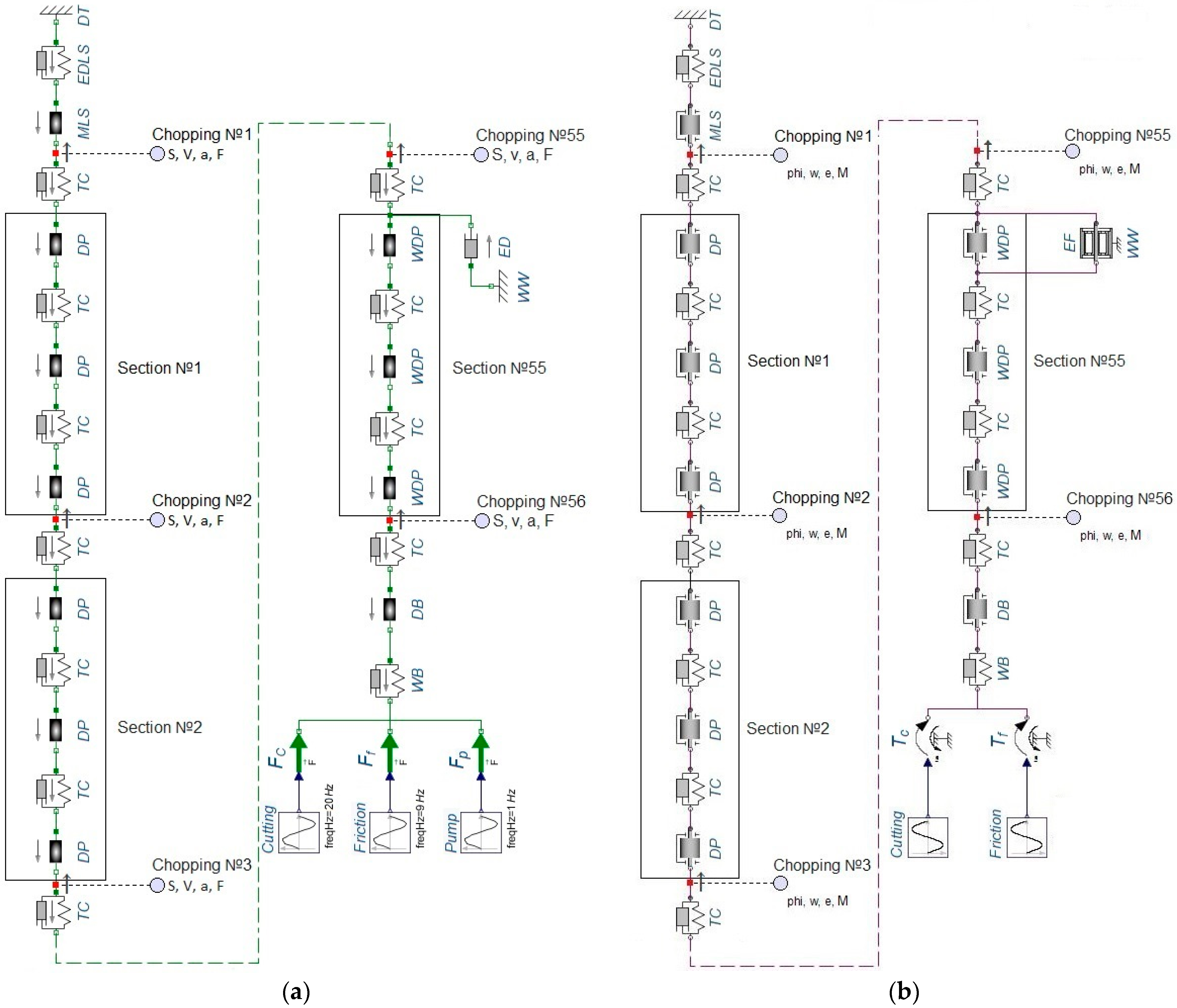
The authors carried out drill string dynamic simulation using MapleSim 2016 (developed by MapleSoft) software with the multi-component synthesis of a mechanical system with concentrated masses. Drill pipes, as components of the system, were presented as a set of concentrated masses, united by elastic dampers and power elements, which determine the “drill string pipe–well bore” concentrated masses interaction. Each drill pipe was supplied in the form of a concentrated mass, and for the calculations, the mass of the pipe immersed in the drilling mud was indicated. The threaded connections of the drill pipes were simulated by mechanical systems for which the stiffness and damping coefficient are specified. The mass of its moving parts, stiffness and damping coefficient were specified for the upper part of the drill string, which was suspended from the derrick using a thermal system. The interaction of the sections of the drill string and the support-centering element with the casing string or the well bore was depicted in the form of a corresponding friction element. The load of the lower over-bit part of the pipe drill string was given in the form of axial dynamic force and torque on the bit for the following load components: cutting, friction, soil, pumping. The axial force change was assumed to be periodic. After that, sections were indicated on the developed computer model, in which kinematic and force factors must be determined. The drill pipe dynamic studied using MapleSim is the synthesis and numerical solution of a system of differential-algebraic equations for the motion of the mechanical system elements. The result of the numerical solution is the relations for displacement, velocity, acceleration, and axial force changes during longitudinal oscillations, as well as the angle of rotation, angular velocity, angular acceleration, and torque during torsional oscillations. Numerical simulations were carried out for the elastic region for drill pipe strings made of different materials, aluminum and titanium alloys and steel, which were used in practice for real wells (YaK–40, No. 209, Hamad–V).

2.3. Methodology of Mathematical Modeling

A mathematical model to access analytically the force interaction of drill strings–conventionally vertical and inclined borehole walls was carried out using a method of composing and solving algebraic and differential equations. In the first stage, these equations were solved analytically to relate the contact and “borehole walls–deformed sections of drill strings” friction forces. In the second stage, numerical models of drill strings were built based on the generalized equations of motion in the MapleSim software product. Dynamic analysis of the equations of motion was carried out using the Runge–Kutta numerical method with further development of spectral characteristics.
Drill strings interact with borehole walls due to the curvature of certain sections of the string during drilling. This phenomenon is observed both on straight and curved intervals of the well. Due to the significant length of the drill string, it loses stability by several loads: compressive, centrifugal, torsional, and hydraulic. Centrifugal forces cause the string to bend along a wave-like curve with a certain half-wavelength. When rotating in a conditionally vertical well, the drill string will begin to lose stability from the moment when the resulting axial load becomes more critical [75]:
P max = 4 π 2 E J l n 2 + q ω 2 l n 2 g π 2 Q ,
where  E  is the modulus of elasticity of the drill string material;  J —the moment of inertia of the drill string section;  ω = π n B / 30 —angular velocity of the string section;  n B —bit rotation frequency; g—acceleration of free fall; q—the weight of one linear meter of the pipe; ln—lengths of the sections and the half-wavelength of the curved string, respectively;  Q —axial static load on the string section.
According to [75], the half-wavelength of a bent string is determined by the formula:
l n = π ω g 2 ± x + x 2 + 4 E J ω 2 q g ,
where x is the distance from the neutral section to the half-wavelength of the bent string position, m is the positive sign (“+”) which refers to the stretched part, and the negative sign (“−”) is for the compressed part of the string.
First, let us consider the static equilibrium of a conditionally vertical section of the drill string when the stability of its straight shape is lost (Figure 1a).
The section of the string is considered as a hinged bent beam, a position of static equilibrium which will correspond to the following system of equations:
F i x = 0 , F i y = 0 , M A = 0 .     R A x P = 0 , R A y + R B y R C = 0 , R C l 1 R B y l n = 0 ,
where  l 1 l 2 l n = l 1 + l 2 —lengths of the sections and the half-wavelength of the curved string, respectively;  R A x —vertical reaction at point A;  R A y R B y —horizontal components of reactions at points A and B, respectively;  R C —reaction of the borehole wall;  P = Q + P D —axial load on the string section;  P D —dynamic component of the axial load.
After solving system (3), we get:  R A x = P ,   R A y = R B y ,   R C = 2 R B y . We will consider the static deflection of the drill string section at  P = Q . To determine the equation of the elastic line, the bending equation and the boundary conditions for the half-wave sections are written:
d 2 y d x 2 + k 2 y = R A y x E J ; x = 0 ,   y = 0 ,   x = l 1 ,   y = δ ,   y = 0 ,
-
for the 2nd half-wave section:
d 2 y d x 2 + k 2 y = R A y x R C x l 1 E J ;   x = l 1 ,   y = δ ,   x = l ,   y = 0 ,
where  δ = D d / 2 —deflection arrow of the drill string;  D —the well diameter;  d —outer diameter of the drill string;  k = P / E J —coefficient.
In mathematics, such Equations (4) and (5) can be considered for very general classes of slice functions [76].
As a result of solving Equations (1) and (2), the equation of the elastic line is obtained:
-
for the 1st half-wave section:
y = δ sin k x sin k l 1 k l 1 cos k l 1 + R A y x P ,
-
for the 2nd half-wave section:
y = δ sin k l 1 k l 1 cos k l 1 + R C P k cos k l 1 sin k x R C P k sin k l 1 cos k x + R A y x R C x l 1 P .
At the same time, the components of the reactions at points A and B and the reaction of the borehole wall are, respectively, equal:
R A y = R B y = R C / 2 ,
R C = 2 P δ k cos k l 1 k l 1 cos k l 1 sin k l 1 .
For the curved section of the wellbore (Figure 1b), the equations of static equilibrium will have the form:
F i n = 0 ; F i τ = 0 ;     R A cos α 2 R B cos α 2 P sin φ 2 P * sin φ 2 + R C = 0 ; R A sin α 2 + R B sin α 2 + P cos φ 2 P * cos φ 2 = 0 ,
where  R A R B  are wall reactions at points A and B; P* is the reaction of the lower part of the drill string to the action of the axial load in the tangential direction, respectively;  α  is the angle of deviation of the axis of the well from the vertical (zenith angle);  φ  is the angle of coverage of the curved trunk by the drill string between points A and B.
If  P = P *  from the system (10), we have that  R A = R B , and if  φ α , the clamping force (reaction of the wall at point C) will be written as follows:
R C = 2 P sin φ 2 + R A cos α 2 2 P sin φ + α 4 .
When considering the dynamic side of the problem, we will use the models of wave processes [77] that occur in the drill string with different types of movement resistance forces. Resistance forces are given in the form of a dissipative function,  f x ,   U ,   ν  which depends on the coordinate  x  of the string section;  U  is the movement of the cross-section of the column with the coordinate  x ν = U / t  is the speed of movement of the cross-section of the string with the coordinate  x . For three schemes of wave processes, the dependences of the axial load on the bit  P D  are presented as functions of the speed of axial displacement of the bit body  ν . In the first case, when there is no dissipative force  f x ,   U ,   ν = 0 , the dynamic component of the axial load has the form:
P D 1 = E F a ν ,
where  F  is the cross-sectional area of the drill string;  a = E / ρ  is the propagation speed of longitudinal disturbances in the string;  ρ  is the density of the drill pipe material.
In the second case, the resistance force is taken as proportional to the speed of movement  f x ,   U ,   ν = 2 μ ν , while the dynamic component of the axial load is written as follows:
P D 2 = E F a 1 4 + μ θ 2 + 1 2 ν + 1 4 + μ θ 2 1 2 ν max 2 ν 2 ,
where  θ  is the circular frequency of vibrations of the drill string;  ν max ν  are the maximum and average values of the oscillation speed, respectively;  μ  is the coefficient of viscous resistance.
In the third case, the drag force obeys the Coulomb–Amonton law when:  f x ,   U ,   ν f 0 s i g n ν :
P D 3 = E F a ν + 2 f 0 π θ 1 ν ν max 2 ,
where  f 0 = μ g sin α —dissipative term.
Taking into account (9) and (11), the friction force of the section of the drill string against the borehole wall is written as follows:
for a conditionally vertical drill string:
F f r = μ R C = μ 2 P δ k cos k l 1 k l 1 cos k l 1 sin k l 1 ;
for a curved drill string:
F f r = μ R C = μ 2 P sin φ + α / 4 .
Taking into account the peculiarities of the process of rotation of the drill string in the drilling mud environment [78], the force of friction of the section of the string against the borehole wall according to the critical axial forces be determined as follows:
F f r = 2 μ q ω 2 l n D d g π 2 + δ Q l n + q 2 .

3. Results and Discussion

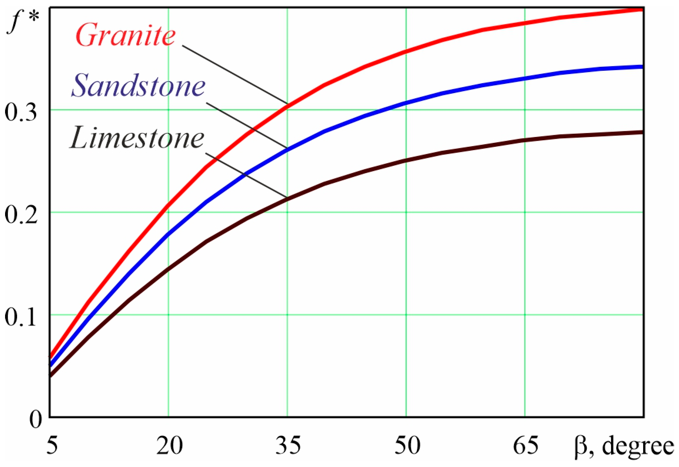
It is known that the “drill string–well bore” coefficient of friction can vary in the range from 0.1 to 0.5 [79]. During calculations in industrial conditions, the coefficient of friction for the pair “drill string–casing” is usually taken as 0.15, and the coefficient of friction for the pair “drill string–filter crust” is 0.3. However, for the conditions of rotary and combined methods of drilling, we adjusted the friction coefficients by simultaneously taking into account the kinematic parameters of translational and rotational movements of sections of the pipe drill string. If the deformed sections of the drill string move along a helical line, then their friction forces against the walls of the well in this case are determined using the combined effective coefficient of friction according to the formula [77]:
f * = μ ν sin β ν sin β 2 + ω D / 2 2 ,
β —the angle of the helix of the helical line along which the point of “drill string–well bore” local contact moves.
Graphical dependences of the effective coefficient of friction, according to Formula (18), are shown in Figure 2 for different types of rocks, granite  μ 1 = 0.5 , sandstone  μ 2 = 0.43 , and limestone  μ 3 = 0.35 , with the following numerical parameters:  ν = 0.5  m/s;  ω = 6.28  s–1 D = 0.127  m [79]. The results of conducted industrial studies showed that the real coefficient of friction between drill string and casing varies in the range from 0.27 to 0.42.
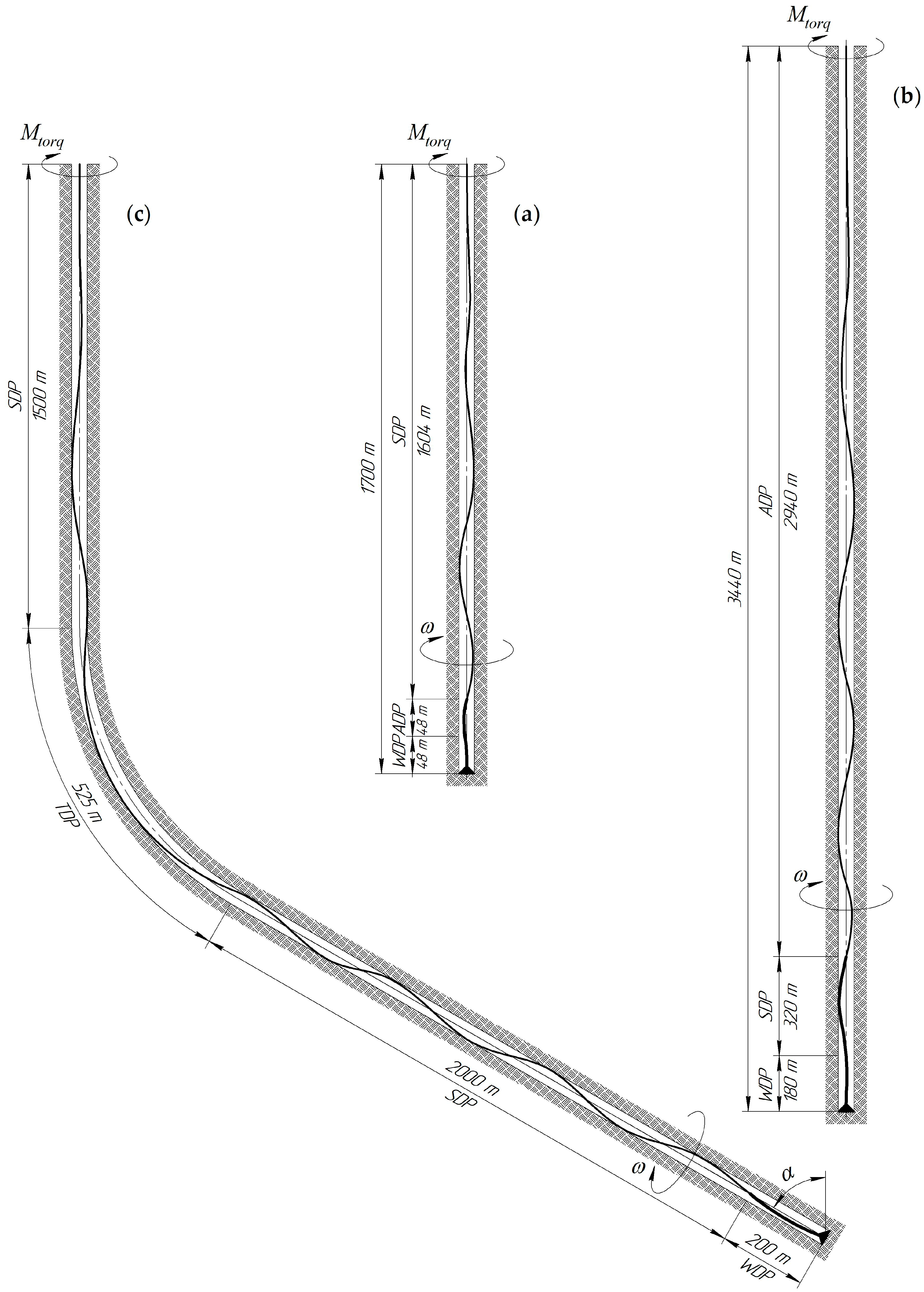
For further research, the following schemes for the arrangement of pipes made of different materials in the arrangement of drill strings during the drilling of wells for the National joint-stock company “Naftogaz of Ukraine” were used:
-
conditional vertical well Yak–40 (Figure 3a);
-
conditional vertical well No. 209 (Figure 3b);
-
obliquely directed well Hamad–V (Figure 3c).
The layout parameters of the drilling tools used for these well drilling processes are as follows (Figure 3).
For the YaK–40 well (1600 m hole): SDP ∅140 mm—1504 m; ADP ∅147 mm—48 m; WDP ∅178 mm—48 m; drill bit—∅214 mm; bit load 180 kN, torque 50 kNm; bit rotation frequency 70–80 rpm; drilling fluid density 1300 kg/m3.
For well No. 209 (bottom hole 3440 m): ADP ∅147 mm—2940 m; SDP ∅140 mm—320 m; WDP ∅178 mm—180 m; chisel—∅214 mm; bit load 180–240 kN; torque 80 kNm; bit rotation frequency 70–80 rpm; drilling fluid density 1250 kg/m3.
For the Hamad–V well (hole 4225 m): SDP ∅140 mm—1500 m; TDP ∅140 mm—525 m; SDP ∅168 mm—2000 m; WDP ∅178 mm—200 m; drill bit—∅214 mm; bit load 120–150 Kn; torque 60 kNm; bit rotation frequency 60 rpm.
According to the given parameters of layouts and mode parameters of drilling, based on [79], simulation models of drill strings were built using the MapleSim software and their numerical implementation was carried out. As a result of the computer calculation, the dependences for displacement, speed, acceleration, axial dynamic force of longitudinal oscillations were obtained, as well as the angle of rotation, and angular velocity, angular acceleration, torque for  i + 1  sections of the string, where  i = 1 , 2 , , n  is the number of string sections (Figure 4).
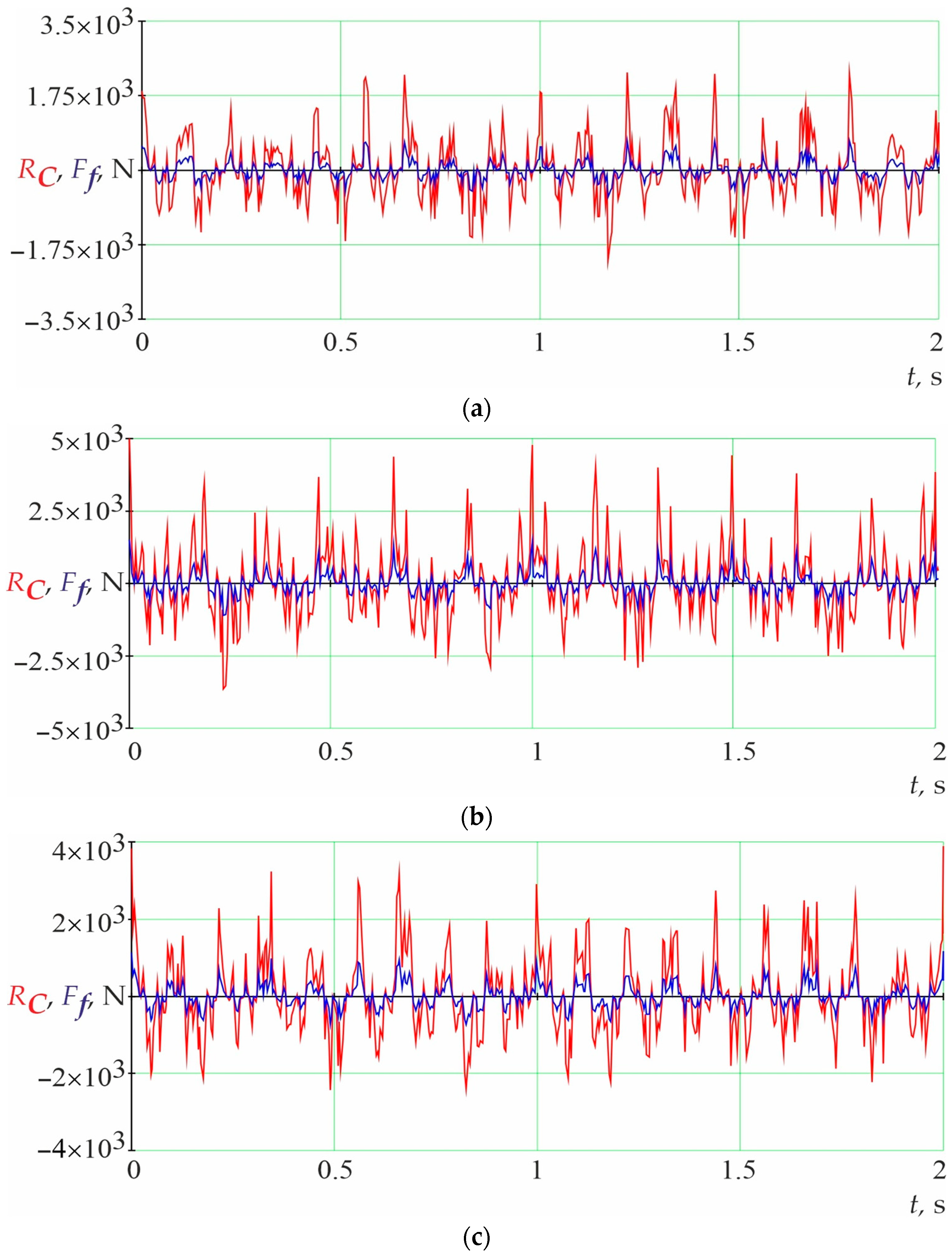
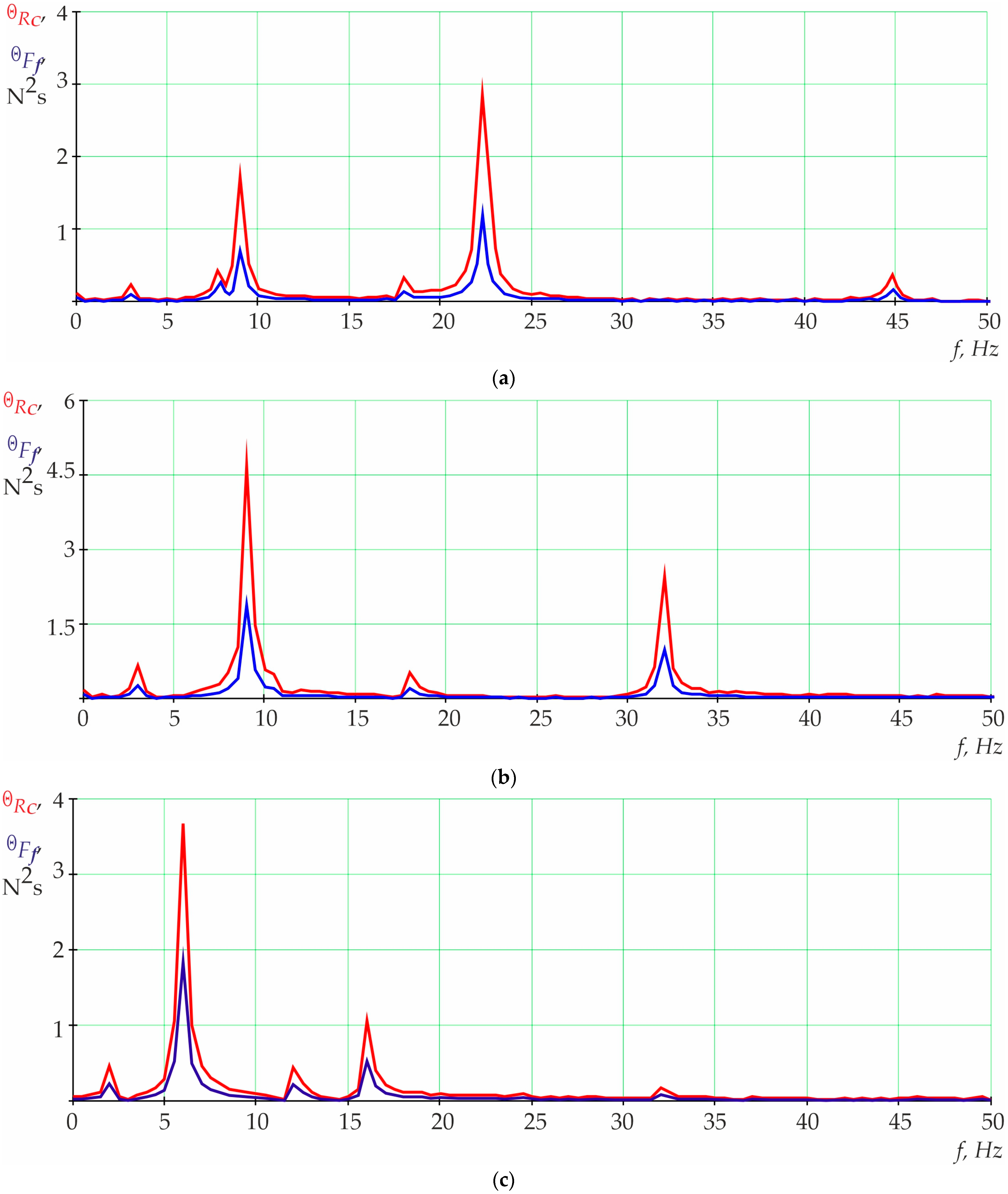
Based on the obtained dependences of force parameters, the pressing and friction forces of the drill strings to the borehole walls (Figure 5) and spectral densities (Figure 6) were studied, taking into account the friction coefficients for the following pairs: “steel–steel”, “aluminum–steel”, “titanium–steel”, “steel–rock”, “aluminium–rock”, “titanium–rock”, as well as several mining-geological and technical-technological parameters of drilling.
The profile of the wells and the layout of the drill string (Figure 3) made it possible to conduct an analytical and experimental assessment of the “drill pipes–borehole walls” interaction. For the sections of the cased and open shaft of the conditionally vertical YaK–40 and No. 209 wells, the normal lateral pressing force and the friction force mainly depend on the axial load on the bit, the geometric dimensions of the half-wave deflection of Figure 5a,b. At the Hamad–V well, intensive interaction of the drill string occurs in the lower section of the technical string and in the section of the zenith angle set (Figure 5c), which significantly affects the duration of maintenance-free operation of the well. The intensity of TDP friction forces on the curved section is significant and is 2–4 kN, which often leads to excessive wear of the drill pipes and loss of their tightness.
It is characteristic that during rotary and combined drilling, the axial movement of the deformed part of the drill string with a lower friction coefficient is possible at a smaller helical angle, when the linear speed component of the rotational movement is greater than the axial one. Therefore, the friction and wear rates of the drill string and casing depend on several factors: the intensity of drill pipes’ pressure on borehole walls, the tribotechnical properties of the drilling fluid, and the total friction path of the points of local contact of the drill string sections against the walls of the well.
The analysis of the obtained results of numerical modeling shows that the contact forces and friction forces of drill strings mainly depend on the axial load on the bit, geometric parameters of its deformation, well curvature profile, and the physical and mechanical properties of the good bore. For drill string operation in a conditionally vertical well with an axial load on the bit of 180 kN, the amplitude value of contact and friction force (Figure 5a) is 2.4 kN and 0.8 kN, respectively. At the same time, the visible frequency range of their changes (Figure 6a) is 8–22 Hz. With an axial load on the bit of 180–240 kN, the amplitude value of contact and friction force (Figure 5b) is 4.8 kN and 1.3 kN, respectively. The visible frequency range of their changes (Figure 6b) is 8–32 Hz. For the operation of the drill string in the area with an inclined well profile with an axial load on the bit of 120–150 kN, the amplitude value of contact and friction force (Figure 5c) is 3.2 kN and 1.1 kN, respectively. At the same time, the visible frequency range of their changes (Figure 6c) is 7–17 Hz.
The pressing and friction forces for SDP sections change more intensively than for TDP or ADP (Figure 5c). The reason for this is that a drill string with an ADP section is 1.1–1.8 times more “flexible” than a solid steel string. This is what shows the greater influence of a solid steel string on the pressing and friction forces (Figure 6a,b) compared to the layout with ADP or TDP sections in the frequency range of 8–22 Hz (Figure 6c), which corresponds to a bit rotation frequency of 70–80 rpm. Therefore, as we can see, the frequency of changes in contact and friction forces in specific areas of the well is proportional to the frequency of longitudinal oscillations of the drill string, and the nature of the oscillations generated by drill bits depends on the configuration of their cutters and rock properties.
The amplitude-frequency analysis of the obtained time characteristics shows that for several layouts, there is a general tendency to increase the amplitudes of changes in frictional forces when moving from the upper pipes of the string to the lower ones. Within the limits of short-term implementation, the change of pressing forces and friction is a random, stationary, ergodic process. Alternate growth and decline of the functions indicate that the amplitudes and frequencies of oscillations are significantly influenced by the frequency of rotation of the drill string (DS), the nature of its interaction with the borehole wall, and the movement of the bit on the holes. This is due to the curvature of the drill string axis and the well, their deviation from being vertical, as well as the shape and rigidity of the hole. Dependencies of friction forces have areas with fast and slow changes in amplitude and frequency. The change in frictional forces within a visible frequency range from 5 to 35 Hz occurs during the unstable operating mode of the drill string, and the speed of their change depends on the stiffness and inertia of the layout.
The conducted research makes it possible to estimate the clamping forces and frictional forces of the deformed sections of the drill strings on the borehole walls during rotary and combined drilling. In the future, it is planned to investigate the relevant parameters of the force interaction of drill strings with borehole walls when using ADP and TDP when drilling with downhole motors.
Article [80] presents a study of the influence of drill string vibration on the stability of a wellbore. The research results provide recommendations for assessing the risk of wellbore instability and are in good agreement with the obtained model dependences of friction and contact forces. Article [81] proposes a model for reducing the friction between the drill string and the wellbore, as well as for increasing the efficiency of axial load transfer and increasing the penetration speed for the directed section of the well. The data are positively correlated with the values of the coefficient of friction of the drill pipes to the wellbore from the three main rocks. The amplitude and frequency of axial load and torque are the main factors affecting the effectiveness of surface vibration [82]. This made it possible in this work to determine the values of the amplitudes and frequencies of changes in contact forces and friction forces for drill string assemblies equipped with sections of steel, aluminum, and titanium drill pipes on vertical, curved, and slanted sections of wells.
The author of [9] carried out a thorough analysis of dynamic processes in nonlinear oscillatory mechanical systems and obtained analytical dependencies for the study of nonlinear mechanical systems of a discrete structure, the analogue of which is a drill string. In [69], the drill string is modeled as a flexible rod with discs at both ends, and one of the discs rotates in a cylinder with fluid. The authors considered different curvatures of the rods to investigate the regularities of the “sticking-sliding” interaction of the drill string with the wellbore. Reference [13] is devoted to the study of transverse and torsional vibrations of a drilling tool armed with both ball and PDS bits. According to the results of these studies, the relationship between the vibration of the drill string and the specific mechanical energy of the blowout destruction was established. The author of [20] established that the drill string layout under conditions of wellbore intense vibrations and uneven pressing can generate intermittent “sliding” and vortex “spinning”. Experimental studies in [15] were carried out with a drill string operating in the mode of high- and low-frequency transverse and torsional vibrations. Based on the research results, a methodology was developed for determining bending and torsional loads in the lower part of the drill string. The author of [82] developed a mathematical model for describing non-stationary oscillations and the stability of a long vertical rectilinear drill string. Through analytical and numerical implementation of the model, the critical values of axial load and torque for different drilling modes were established.
Therefore, the advantages of the model developed by us over the well-known ones [9,13,15,20,69,82] lie in the possibility of estimating the parameters of stability and dynamic load, taking into account the frictional forces of parts of the drill string against the walls of vertical, curved, and inclined sections of the well. The information about the use of pipes made of various materials, aluminum and titanium alloys and steel, in the layouts of active drill strings gives special importance to this work.
It should be noted that the difficulty of drill string numerical model development [79] is that their dynamics are described, as a rule, by a system of differential-algebraic equations, which in most cases, are nonlinear, and, therefore, it is quite difficult to obtain their solution in an explicit form. On the other hand, compiling the differential equations of motion of a mechanical system with a large number of structural elements and degrees of freedom is a complex process. Therefore, during the development of these numerical models, the authors of the article resorted to certain simplifications that did not significantly affect the accuracy of the results of the pipe column research, while the simulation was carried out for real wells (YaK–40, No. 209, Hamad–V).
In further studies, the influence of dampers during well drilling on the dynamics of drill strings composed of different materials will be studied.

4. Conclusions

Based on analytical and numerical modeling, an assessment of the “drill string–well bore” force interaction of conditionally vertical and directional wells during their use in ADP and TDP configurations combined with SDP was carried out. Based on the results of the research, several features have been established that should be taken into account during the design and operation of drill strings. The intensity of changes in the pressing and friction force charts for SDP sections is greater than for TDP or ADP; this indicates the greater influence of a solid steel string on the magnitude of the clamping and friction forces in comparison with the arrangement with ADP or TDP sections in a frequency range of 8–22 Hz, which corresponds to a bit rotation frequency of 70–80 rpm. A drill string with an ADP section is 1.1–1.8 times more flexible than a solid steel string. Accordingly, the use of an ADP section in a layout with the condition of selecting its specified length makes it possible to increase the rotation frequency of the bit without the risk of damaging the drill string elements. The use of a TDP section on the curved sections of a well leads to a decrease in the amplitude of friction force fluctuations in a narrow frequency range of 5–8 Hz at a bit rotation frequency of 60 rpm due to an increase in the “flexibility” of the string system. The degree of change in the contact and friction forces of the pipes against the walls of the well depends on the location of the ADP or TDP installation in the drill string layout, their length, and the geometric dimensions of the deflection half-wave lengths.

Author Contributions

Conceptualization, Y.G., M.B., L.R. and O.S.; methodology, B.G., Y.G., M.P., O.S. and A.A.-T.; software, B.G., Y.G., M.B., O.S. and T.P.; validation, B.G., Y.G., L.R., M.P. and O.S.; formal analysis, B.G., Y.G., M.P. and O.S.; investigation, Y.G., M.P., O.S. and A.A.-T.; resources, B.G., M.B., L.R. and O.S.; data curation, Y.G., L.R. and O.S.; writing—original draft preparation, Y.G., L.R., O.S. and A.A.-T.; writing—review and editing, M.B., B.G., Y.G., L.R. and O.S.; visualization, Y.G., L.R., O.S. and A.A.-T.; supervision, Y.G., L.R. and O.S.; project administration, B.G., M.B. and L.R.; funding acquisition, B.G., M.B. and L.R. All authors have read and agreed to the published version of the manuscript.

Funding

This research was funded by the Ministry of Science and Education of Ukraine for the grant to implement projects 0122U002082 and 0123U101858.

Data Availability Statement

The data are contained within this article.

Acknowledgments

The authors express their sincere gratitude and respect to the Armed Forces of Ukraine, who made it possible to complete the preparation of this article for publication. The authors are also grateful to the editor and reviewers for their comments that helped improve the content of this paper.

Conflicts of Interest

The authors declare no conflict of interest.

References

  1. Ma, T.; Chen, P.; Zhao, J. Overview on vertical and directional drilling technologies for the exploration and exploitation of deep petroleum resources. Géoméch. Geophys. Geo-Energy Geo-Resour. 2016, 2, 365–395. [Google Scholar] [CrossRef]
  2. El Sabeh, K.; Gaurina-Međimurec, N.; Mijić, P.; Medved, I.; Pašić, B. Extended-Reach Drilling (ERD)—The Main Problems and Current Achievements. Appl. Sci. 2023, 13, 4112. [Google Scholar] [CrossRef]
  3. Tong, H.; Shao, Y. Mechanical Analysis of DS in Horizontal Directional Drilling. Appl. Sci. 2022, 12, 3145. [Google Scholar] [CrossRef]
  4. Jeong, J.; Lim, C.; Park, B.-C.; Bae, J.; Shin, S.-c. Multi-Objective Optimization of Drilling Trajectory Considering Buckling Risk. Appl. Sci. 2022, 12, 1829. [Google Scholar] [CrossRef]
  5. Gu, Y.; Huang, W.; Gao, D. Directional Drilling Limits Analysis Based on Downhole Drill String Mechanics for Shale Gas Cluster Well Engineering. Arab. J. Sci. Eng. 2022, 47, 11255–11267. [Google Scholar] [CrossRef]
  6. Chudyk, I.I.; Dudych, I.F.; Sudakova, D.A.; Voloshyn, Y.D.; Bogoslavets, V.V. Influence of Drilling Mud Pulsations on Well Cleanout Efficiency. Nauk. Visnyk Natsionalnoho Hirnychoho Universytetu 2023, 2023, 48–53. [Google Scholar] [CrossRef]
  7. Kessai, I.; Benammar, S.; Doghmane, M.Z.; Tee, K.F. Drill Bit Deformations in Rotary Drilling Systems under Large-Amplitude Stick-Slip Vibrations. Appl. Sci. 2020, 10, 6523. [Google Scholar] [CrossRef]
  8. Grydzhuk, J.; Dzhus, A.; Yurych, A.; Yurych, L.; Dorokhov, M.; Livinskyi, A. Improving the technique for assessing the condition and predicting the wear of the rock destruction tool equipment. East.-Eur. J. Enterp. Technol. 2022, 4, 103–109. [Google Scholar] [CrossRef]
  9. Chen, X.; Yang, J.; Gao, D. Drilling Performance Optimization Based on Mechanical Specific Energy Technologies; Drilling; Samsuri, A., Ed.; IntechOpen Limited: London, UK, 2018. [Google Scholar] [CrossRef]
  10. Lashari, S.; Takbiri-Borujeni, A.; Fathi, E. Drilling performance monitoring and optimization: A data-driven approach. J. Petrol. Explor. Prod. Technol. 2019, 9, 2747–2756. [Google Scholar] [CrossRef]
  11. Sridharan, C.; Suresh Kumar, G. Drilling Efficiency Improvement and Rate of Penetration Optimization by Machine Learning and Data Analytics. Int. J. Math. Eng. Manag. Sci. 2020, 5, 381–394. [Google Scholar] [CrossRef]
  12. Khajiyeva, L.A.; Andrianov, I.V.; Sabirova, Y.F.; Kudaibergenov, A.K. Analysis of Drill-String Nonlinear Dynamics Using the Lumped-Parameter Method. Symmetry 2022, 14, 1495. [Google Scholar] [CrossRef]
  13. Huang, F.; Yang, J.; Li, B.; Gan, L.; Feng, Q. Study on dynamic characteristics of drill string in deep-water riserless drilling. Adv. Mech. Eng. 2023, 15, 16878132221142113. [Google Scholar] [CrossRef]
  14. O’Reilly, O.M. Kirchhoff’s Rod Theory. In Modeling Nonlinear Problems in the Mechanics of Strings and Rods; Interaction of Mechanics and Mathematics; Springer: Cham, Switzerland, 2017; pp. 187–268. [Google Scholar] [CrossRef]
  15. Ghasemloonia, A.; Rideout, D.G.; Butt, S.D. A review of drillstring vibration modeling and suppression methods. J. Pet. Sci. Eng. 2015, 131, 150–164. [Google Scholar] [CrossRef]
  16. Prysyazhnyuk, P.; Molenda, M.; Romanyshyn, T.; Ropyak, L.; Romanyshyn, L.; Vytvytskyi, V. Development of a hardbanding material for drill pipes based on high-manganese steel reinforced with complex carbides. Acta Montan. Slovaca 2022, 27, 685–696. [Google Scholar] [CrossRef]
  17. Gajdzik, B.; Sroka, W. Analytic study of the capital restructuring processes in metallurgical enterprises around the world and in Poland [Analitički studij kapitalnog restrukturiranja procesa metalurških tvrtki u svijetu i poljskoj]. Metalurgija 2012, 51, 265–268. [Google Scholar]
  18. Teodoriu, C.; Bello, O. An Outlook of Drilling Technologies and Innovations: Present Status and Future Trends. Energies 2021, 14, 4499. [Google Scholar] [CrossRef]
  19. Grydzhuk, J.; Chudyk, I.; Slabyi, O.; Mosora, Y.; Kovbaniuk, M.; Krynke, M. Mathematical modeling of the stress-strain state of the annular preventer seal using the theory of reinforced shells. Prod. Eng. Arch. 2022, 28, 375–380. [Google Scholar] [CrossRef]
  20. Shlyun, N.V.; Gulyayev, V.I. Buckling of a drill-string in two-sectional bore-holes. Int. J. Mech. Sci. 2020, 172, 105427. [Google Scholar] [CrossRef]
  21. Vytyaz, O.; Chudyk, I.; Mykhailiuk, V. Study of the effects of drilling string eccentricity in the borehole on the quality of its cleaning. In New Developments in Mining Engineering; CRC Press: Boca Raton, FL, USA, 2015; pp. 591–595. [Google Scholar] [CrossRef]
  22. Onysko, O.; Borushchak, L.; Kopei, V.; Lukan, T.; Medvid, I.; Vryukalo, V. Computer Studies of the Tightness of the Drill String Connector Depending on the Profile of Its Tapered Thread. Lect. Notes Netw. Syst. 2020, 128, 720–729. [Google Scholar] [CrossRef]
  23. Kopei, V.; Onysko, O.; Panchuk, V.; Pituley, L.; Schuliar, I. Influence of Working Height of a Thread Profile on Quality Indicators of the Drill-String Tool-Joint. In Advanced Manufacturing Processes III; InterPartner 2021; Tonkonogyi, V., Ivanov, V., Trojanowska, J., Oborskyi, G., Pavlenko, I., Eds.; Lecture Notes in Mechanical Engineering; Springer: Cham, Switzerland, 2022; pp. 395–404. [Google Scholar] [CrossRef]
  24. Chudyk, I.; Poberezhny, L.; Hrysanchuk, A.; Poberezhna, L. Corrosion of drill pipes in high mineralized produced waters. Procedia Struct. Integr. 2019, 16, 260–264. [Google Scholar] [CrossRef]
  25. Vynar, V.A.; Dovhunyk, V.M.; Student, M.M. Methodical specific features of tribocorrosion investigations. Mater. Sci. 2011, 46, 633–639. [Google Scholar] [CrossRef]
  26. Pokhmurskii, V.I.; Vynar, V.A.; Vasyliv, C.B.; Ratska, N.B. Effects of hydrogen exposure on the mechanical and tribological properties of α-titanium surfaces. Wear 2013, 306, 47–50. [Google Scholar] [CrossRef]
  27. Shats’kyi, I.P.; Makoviichuk, M.V. Contact interaction of crack lips in shallow shells in bending with tension. Mater. Sci. 2005, 41, 486–494. [Google Scholar] [CrossRef]
  28. Andreikiv, O.Y.; Dolins’ka, I.Y.; Shtoiko, I.P.; Raiter, O.K.; Matviiv, Y.Y. Evaluation of the Residual Service Life of Main Pipelines with Regard for the Action of Media and Degradation of Materials. Mater. Sci. 2019, 54, 638–646. [Google Scholar] [CrossRef]
  29. Kusyi, Y.; Stupnytskyy, V.; Onysko, O.; Dragašius, E.; Baskutis, S.; Chatys, R. Optimization synthesis of technological parameters during manufacturing of the parts. Eksploat. I Niezawodn. Maint. Reliab. 2022, 24, 655–667. [Google Scholar] [CrossRef]
  30. Petrakov, Y.; Danylchenko, M. A Time-Frequency Approach to Ensuring Stability of Machining by Turning. East.-Eur. J. Enterp. Technol. 2022, 6, 85–92. [Google Scholar] [CrossRef]
  31. Danylchenko, Y.; Storchak, M.; Danylchenko, M.; Petryshyn, A. Cutting Process Consideration in Dynamic Models of Machine Tool Spindle Units. Machines 2023, 11, 582. [Google Scholar] [CrossRef]
  32. Barandych, K.S.; Vysloukh, S.P.; Antonyuk, V.S. Ensuring Fatigue Life of Parts During Finish Turning with Cubic Boron Nitride Tools. J. Superhard Mater. 2018, 40, 206–215. [Google Scholar] [CrossRef]
  33. Bembenek, M.; Dzienniak, D.; Dzindziora, A.; Sułowski, M.; Ropyak, L. Investigation of the Impact of Selected Face Milling Parameters on the Roughness of the Machined Surface for 1.4301 Steel. Adv. Sci. Technol. Res. J. 2023, 17, 299–312. [Google Scholar] [CrossRef]
  34. Petrakov, Y.; Danylchenko, Y.; Sapon, S.; Sikailo, M. Surface Relief Formation in Peripheral End Milling. In Advances in Design, Simulation and Manufacturing VI; Notes in Mechanical Engineering; Springer: Cham, Switzerland, 2023; pp. 316–326. [Google Scholar] [CrossRef]
  35. Smokvyna, V.V.; Lavrinenko, V.I.; Ilnytska, H.D. Defectiveness of Low Strength Synthetic Diamond Grains: Negative and Positive Aspects in Case of Using Them in a Grinding Tool. J. Superhard Mater. 2023, 45, 306–315. [Google Scholar] [CrossRef]
  36. Onysko, O.; Medvid, I.; Panchuk, V.; Rodic, V.; Barz, C. Geometric Modeling of Lathe Cutters for Turning High-Precision Stainless Steel Tapered Threads. In Advances in Design, Simulation and Manufacturing IV. DSMIE 2021; Ivanov, V., Trojanowska, J., Pavlenko, I., Zajac, J., Peraković, D., Eds.; Lecture Notes in Mechanical Engineering; Springer: Cham, Switzerland, 2021; Volume 1, pp. 472–480. [Google Scholar] [CrossRef]
  37. Medvid, I.; Onysko, O.; Panchuk, V.; Pituley, L.; Schuliar, I. Kinematics of the Tapered Thread Machining by Lathe: Analytical Study. In Proceedings of the Advanced Manufacturing Processes II 2020; Tonkonogyi, V., Ivanov, V., Trojanowska, J., Oborskyi, G., Grabchenko, A., Pavlenko, I., Edl, M., Kuric, I., Dasic, P., Eds.; Lecture Notes in Mechanical Engineering; Springer: Cham, Switzerland, 2021; pp. 555–565. [Google Scholar] [CrossRef]
  38. Trembach, B.O.; Sukov, M.G.; Vynar, V.A.; Trembach, I.O.; Subbotina, V.V.; Rebrov, O.Y.; Rebrova, O.M.; Zakiev, V.I. Effect of Incomplete Replacement of Cr for Cu in the Deposited Alloy of Fe–C–Cr–B–Ti Alloying System with a Medium Boron Content (0.5% wt.) on its Corrosion Resistance. Metallofiz. I Noveishie Tekhnologii 2022, 44, 493–513. [Google Scholar] [CrossRef]
  39. Tarelnik, V.B.; Gaponova, O.P.; Konoplyantschenko, E.V.; Yevtushenko, N.S.; Gerasimenko, V.A. Analysis of the structural state of the surface layer after electro-erosive alloying. II. Peculiarities of the formation of electroerosive coatings on special steels and stops by hard wear-resistant and soft antifriction materials. Metallofiz. I Noveishie Tekhnologii 2018, 11, 795–815. [Google Scholar] [CrossRef]
  40. Ropyak, L.; Shihab, T.; Velychkovych, A.; Bilinskyi, V.; Malinin, V.; Romaniv, M. Optimization of Plasma Electrolytic Oxidion Technological Parameters of Deformed Aluminum Alloy D16T in Flowing Electrolyte. Ceramics 2023, 6, 146–167. [Google Scholar] [CrossRef]
  41. Ropyak, L.; Shihab, T.; Velychkovych, A.; Dubei, O.; Tutko, T.; Bilinskyi, V. Design of a Two-Layer Al–Al2O3 Coating with an Oxide Layer Formed by the Plasma Electrolytic Oxidation of Al for the Corrosion and Wear Protections of Steel. Prog. Phys. Met. 2023, 24, 319–365. [Google Scholar] [CrossRef]
  42. Shatskyi, I.; Makoviichuk, M.; Ropyak, L.; Velychkovych, A. Analytical Model of Deformation of a Functionally Graded Ceramic Coating under Local Load. Ceramics 2023, 6, 1879–1893. [Google Scholar] [CrossRef]
  43. Pashechko, M.I.; Shyrokov, V.V.; Duryahina, Z.A.; Vasyliv, K.B. Structure and corrosion-mechanical properties of the surface layers of steels after laser alloying. Mater. Sci. 2003, 39, 108–117. [Google Scholar] [CrossRef]
  44. Bembenek, M.; Prysyazhnyuk, P.; Shihab, T.; Machnik, R.; Ivanov, O.; Ropyak, L. Microstructure and Wear Characterization of the Fe–Mo–B–C—Based Hardfacing Alloys Deposited by Flux-Cored Arc Welding. Materials 2022, 15, 5074. [Google Scholar] [CrossRef]
  45. Prysyazhnyuk, P.; Di Tommaso, D. The thermodynamic and mechanical properties of Earth-abundant metal ternary boride Mo2(Fe,Mn)B2 solid solutions for impact- and wear-resistant alloys. Mater. Adv. 2023, 4, 3822–3838. [Google Scholar] [CrossRef]
  46. Trembach, B.; Balenko, O.; Davydov, V.; Brechko, V.; Trembach, I.; Kabatskyi, O. Prediction the Melting Characteristics of Self-Shielded Flux Cored arc Welding (FCAW–S) with Exothermic Addition (CuO–Al). In Proceedings of the 2022 IEEE 4th International Conference on Modern Electrical and Energy System, MEES 2022, Kremenchuk, Ukraine, 20–23 October 2022; pp. 1–6. [Google Scholar] [CrossRef]
  47. Prysyazhnyuk, P.M.; Shihab, T.A.; Panchuk, V.H. Formation of the Structure of Cr3C2–MNMts 60-20-20 Cermets. Mater. Sci. 2016, 52, 188–193. [Google Scholar] [CrossRef]
  48. Pryhorovska, T.O.; Chaplinskiy, S.S.; Kudriavtsev, I.O. Finite element modelling of rock mass cutting by cutters for PDC drill bits. Shiyou Kantan Yu Kaifa/Pet. Explor. Dev. 2015, 42, 812–816. [Google Scholar] [CrossRef]
  49. Jinping, Y.; Deyong, Z.; Yuanxiu, S.; Yin, Z. Simulation and Experimental Study of the Rock Breaking Mechanism of Personalized Polycrystalline Diamond Compact Bits. J. Eng. Sci. Technol. Rev. 2020, 13, 122–131. [Google Scholar] [CrossRef]
  50. Tatsiy, R.; Stasiuk, M.; Pazen, O.; Vovk, S. Modeling of Boundary-Value Problems of Heat Conduction for Multilayered Hollow Cylinder. In Proceedings of the 2018 International Scientific-Practical Conference Problems of Infocommunications. Science and Technology (PIC S&T), Kharkiv, Ukraine, 9–12 October 2018; pp. 21–25. [Google Scholar] [CrossRef]
  51. Bandura, A.; Skaskiv, O. Boundedness of the L-index in a direction of entire solutions of second order partial differential equation. Acta Et Comment. Univ. Tartu. De Math. 2018, 22, 223–234. [Google Scholar] [CrossRef]
  52. Tatsiy, R.M.; Pazen, O.Y.; Vovk, S.Y.; Kharyshyn, D.V. Direct method of studying heat exchange in multilayered bodies of basic geometric forms with imperfect heat contact. Naukovyi Visnyk Natsionalnoho Hirnychoho Universytetu 2021, 2021, 60–67. [Google Scholar] [CrossRef]
  53. Panevnik, D.A.; Velichkovich, A.S. Assessment of the stressed state of the casing of the above-bit hydroelevator. Neftyanoe Khozyaystvo Oil Ind. 2017, 1, 70–73. [Google Scholar]
  54. Kotsyubynsky, V.; Shyyko, L.; Shihab, T.; Prysyazhnyuk, P.; Aulin, V.; Boichuk, V. Multilayered MoS2/C nanospheres as high performance additives to lubricating oils. Mater. Today Proc. 2019, 35, 538–541. [Google Scholar] [CrossRef]
  55. Moisyshyn, V.M.; Lyskanych, M.V.; Borysevych, L.V.; Kolych, N.B.; Zhovniruk, R.A. Integral Indicators of Change of Drilling Column Vibration-Criterion for Assessing of Roller Cone Bit Wear. Metallofiz. I Noveishie Tekhnologii 2019, 41, 1087–1102. [Google Scholar] [CrossRef]
  56. Dutkiewicz, M.; Gołębiowska, I.; Shatskyi, I.; Shopa, V.; Velychkovych, A. Some aspects of design and application of inertial dampers. MATEC Web Conf. 2018, 178, 06010. [Google Scholar] [CrossRef]
  57. Moisyshyn, V.M.; Slabyi, O.O. Creation of the vibroprotective device for adjustment of dynamics of a column of steel drill pipes and a bit. Metallofiz. I Noveishie Tekhnologii 2018, 40, 541–550. [Google Scholar] [CrossRef]
  58. Shats’kyi, I.P.; Shopa, V.M.; Velychkovych, A.S. Development of full-strength elastic element section with open shell. Strength Mater. 2021, 53, 277–282. [Google Scholar] [CrossRef]
  59. Dutkiewicz, M.; Velychkovych, A.; Shatskyi, I.; Shopa, V. Efficient Model of the Interaction of Elastomeric Filler with an Open Shell and a Chrome-Plated Shaft in a Dry Friction Damper. Materials 2022, 15, 4671. [Google Scholar] [CrossRef]
  60. Shatskyi, I.; Velychkovych, A. Analytical Model of Structural Damping in Friction Module of Shell Shock Absorber Connected to Spring. Shock Vib. 2023, 2023, 4140583. [Google Scholar] [CrossRef]
  61. Velichkovich, A.S.; Dalyak, T.M. Assessment of stressed state and performance characteristics of jacketed spring with a cut for drill shock absorber. Chem. Pet. Eng. 2015, 51, 188–193. [Google Scholar] [CrossRef]
  62. Petlovanyi, M.; Lozynskyi, V.; Saik, P.; Sai, K. Predicting the producing well stability in the place of its curving at the underground coal seams gasification. E3S Web Conf. 2019, 123, 01019. [Google Scholar] [CrossRef]
  63. Tyrlych, V.; Moisyshyn, V. Predicting remaining lifetime of drill pipes basing upon the fatigue crack kinetics within a pre-critical period. Min. Miner. Depos. 2019, 13, 127–133. [Google Scholar] [CrossRef]
  64. Moisyshyn, V.; Yacyshyn, V.; Vytyaz, O. The use of the spatial characteristics technique with the view of estimating the explosion wave impact on the stuck drilling string zone. Arch. Min. Sci. 2012, 57, 601–618. [Google Scholar] [CrossRef]
  65. Gulyayev, V.; Shlyun, N. Influence of friction on buckling of a drill string in the circular channel of a bore hole. Pet. Sci. 2016, 13, 698–711. [Google Scholar] [CrossRef]
  66. Li, Z.; Zhang, C.; Ren, W.; Ma, J. Study of Radial Vibration Impact on Friction and Torque of Rotary Drill String. Shock Vib. 2020, 2020, 8852530. [Google Scholar] [CrossRef]
  67. Vytyaz, O.Y.; Hrabovskyy, R.S.; Artym, V.I.; Tyrlych, V.V. Effect of geometry of internal crack-like defects on assessing trouble-free operation of long-term operated pipes of drill string. Metallofiz. I Noveishie Tekhnologii 2020, 42, 1715–1727. [Google Scholar] [CrossRef]
  68. Chen, Y.; He, C.; Zhou, X.; Yu, H. Analysis of factors affecting drilling friction and investigation of the friction reduction tool in horizontal wells in Sichuan. Adv. Mech. Eng. 2019, 11, 1687814019862963. [Google Scholar] [CrossRef]
  69. Auriol, J.; Shor, R.; Niculescu, S.; Kazemi, N. Estimating Drill String Friction with Model-Based and Data-Driven Methods. In Proceedings of the 2022 American Control Conference (ACC), Atlanta, GA, USA, 8–10 June 2022; pp. 3464–3469. [Google Scholar] [CrossRef]
  70. Li, X.; Fan, Y.; Li, J.; Su, X.; Zhan, S.; Hu, G.; He, Y.; Zhang, M. Research on the Influence of a Cuttings Bed on Drill String Friction Torque in Horizontal Well Sections. Processes 2022, 10, 2061. [Google Scholar] [CrossRef]
  71. Shatskii, I.P.; Perepichka, V.V. Shock-wave propagation in an elastic rod with a viscoplastic external resistance. J. Appl. Mech. Tech. Phys. 2013, 54, 1016–1020. [Google Scholar] [CrossRef]
  72. Shatskyi, I.; Perepichka, V. Problem of dynamics of an elastic rod with decreasing function of elastic-plastic external resistance. In Dynamical Systems in Applications, DSTA 2017; Awrejcewicz, J., Ed.; Springer Proceedings in Mathematics & Statistics; Springer: Cham, Switzerland, 2018; Volume 249, pp. 335–342. [Google Scholar] [CrossRef]
  73. Long, Y.; Wang, X.; Wang, P.; Zhang, F. A Method of Reducing Friction and Improving the Penetration Rate by Safely Vibrating the Drill-String at Surface. Processes 2023, 11, 1242. [Google Scholar] [CrossRef]
  74. Shi, X.L.; Wen-Jun Huang, W.J.; Gao, D.L. Mechanical behavior of drillstring with drag reduction oscillators and its effects on sliding drilling limits. Pet. Sci. 2021, 18, 1689–1697. [Google Scholar] [CrossRef]
  75. Lyskanych, M.V.; Grydzhuk, J.S.; Popadyuk, I.Y. Assessment of the impact of bending loads and vibrations on the stress state of the drill string. Explor. Dev. Oil Gas Depos. 2003, 4, 56–61. Available online: http://elar.nung.edu.ua/handle/123456789/5399 (accessed on 27 October 2023).
  76. Bandura, A.; Martsinkiv, M.; Skaskiv, O. Slice holomorphic functions in the unit ball having a bounded L-index in direction. Axioms 2021, 10, 4. [Google Scholar] [CrossRef]
  77. Grydzhuk, J.S. Forecasting of Durability of Members of a Drill String at a Percussive Offloading. Ph.D. Thesis, Ivano-Frankivsk National Technical University of Oil and Gas, Ivano-Frankivsk, Ukraine, 2013. Specialty 05.05.12—Machines of Oil and Gas Industry. 200p. Available online: https://view.officeapps.live.com//op/view.aspx?src=https%3A%2F%2Fmydisser.com%2Fdfiles%2F62303578.doc&wdOrigin=BROWSELINK (accessed on 27 October 2023).
  78. Chudyk, I.I.; Lavynyukova, T.G.; Grydzhuk, J.S.; Hnatkivskyi, V.M. Study of the Processes of Rotation of the Drill String in a Curved Well in the Drilling Mud Environment. In Rock-Destructive and Metalworking Instrument—Technique and Technology of Its Manufacture and Application; Novikov, N.V., Ed.; Institute of Superhard Materials Named after V.M. Bakulya of the National Academy of Sciences of Ukraine: Kyiv, Ukraine, 2011; Volume 14, pp. 102–108. Available online: http://dspace.nbuv.gov.ua/handle/123456789/63213 (accessed on 27 October 2023).
  79. Grydzhuk, J.S. Development of Scientific Bases for the Engineering of Dynamic Processes of Pipe and Rod Columns at Drilling and Operation of Wells. Ph.D. Thesis, Ivano-Frankivsk National Technical University of Oil and Gas, Ivano-Frankivsk, Ukraine, 2020. Speciality 05.05.12—Machines of Oil and Gas Industry. Available online: http://elar.nung.edu.ua/handle/123456789/8236 (accessed on 27 October 2023).
  80. Shan, Y.; Xue, Q.; Wang, J.; Li, Y.; Wang, C. Analysis of the Influence of Downhole Drill String Vibration on Wellbore Stability. Machines 2023, 11, 762. [Google Scholar] [CrossRef]
  81. Wang, C.; Chen, W.; Wu, Z.; Li, J.; Liu, G. Stick–Slip Characteristics of Drill Strings and the Related Drilling Parameters Optimization. Processes 2023, 11, 2783. [Google Scholar] [CrossRef]
  82. Athanasiou, P.; Hadi, Y. Simulation of Oil Well Drilling System Using Distributed–Lumped Modelling Technique. Modelling 2020, 1, 175–197. [Google Scholar] [CrossRef]
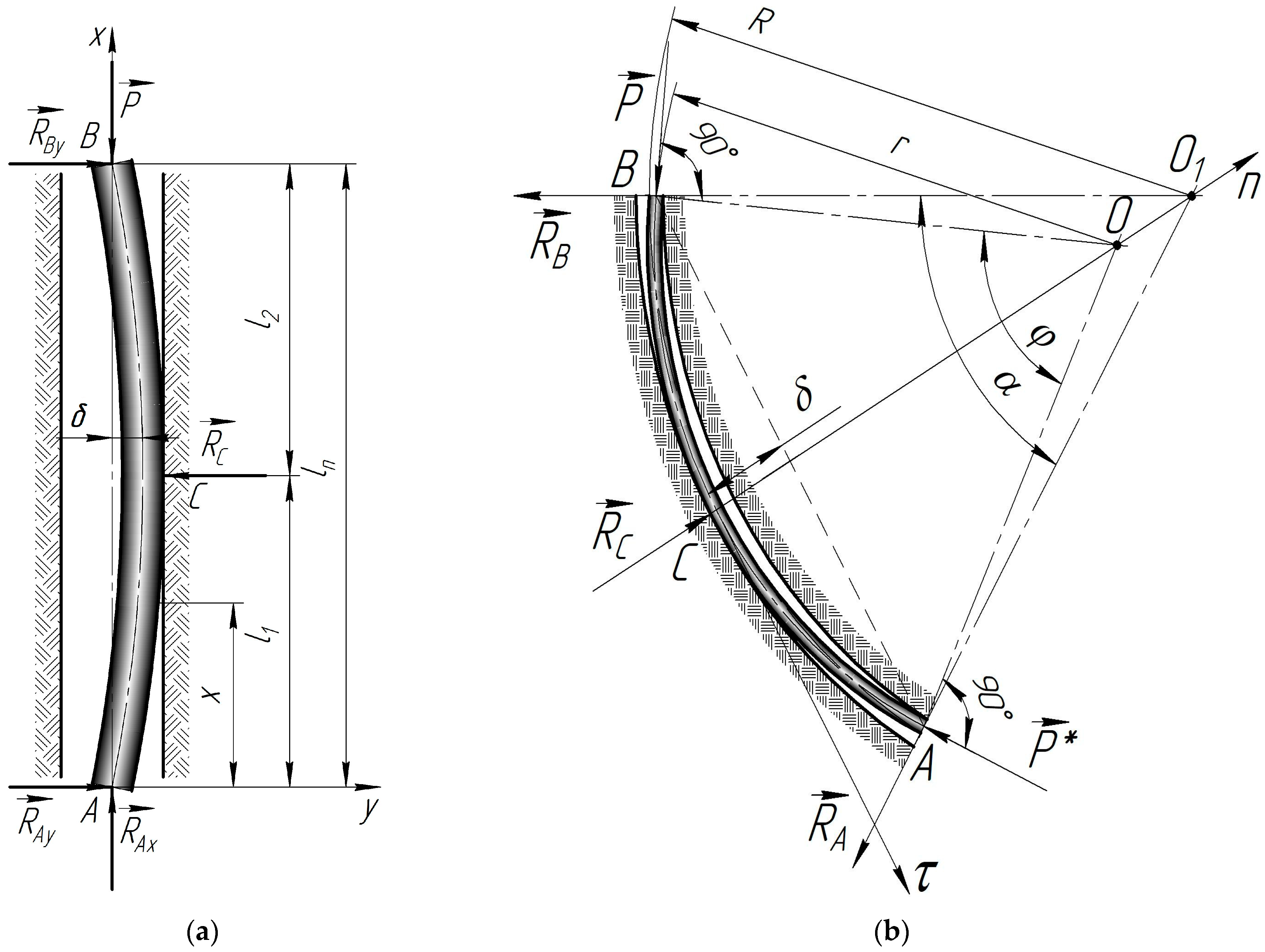
Figure 1. Calculation diagram of half-wave loading of a drill string in a conditionally vertical (a) and curved (b) wellbore.
Energies 17 00301 g001
Figure 2. The dependence of the effective coefficient of friction refers to the drill string angle of the helix when interacting with various rocks in the well [79].
Energies 17 00301 g002
Figure 3. Schemes of well profiles and contact of drill strings with the borehole walls for various wells when the design depth is reached: (a) YaK–40; (b) No. 209; (c) Hamad–V.
Energies 17 00301 g003
Figure 4. Numerical models to study the kinematic and force parameters of longitudinal (a) and torsional (b) vibrations of the drill string pipes: DT—drilling tower; EDLS—elastic damper lifting system; MLS—mechanical lifting system; TC—threaded connection; DP—drill pipe; WDP—weighted drill pipe; EF—element of friction; ED—element of damping; WW—well wall; DB—drill bit; WB—well blowout; s—axial displacement; v—axial speed; a—axial acceleration; F—axial force; phi—rotation angle; w—angular velocity; e—angular acceleration; M—torque.
Energies 17 00301 g004
Figure 5. Theoretical dependences of the pressure and friction forces of the drill string sections on the borehole walls as a function of time when the design depth is reached: (a) Yak–40, L = 1552 m; (b) No. 209, L = 2550 m; (c) Hamad–V, L = 2025 m.
Energies 17 00301 g005
Figure 6. Spectral densities of the pressing forces and friction of the drill string sections to the borehole walls when the design depth is reached: (a) Yak–40, L = 1552 m; (b) No. 209, L = 2550 m; (c) Hamad–V, L = 2025 m.
Energies 17 00301 g006
Table 1. Physical and mechanical properties of the materials for drill pipes.
Materials
Drill Pipes
Ultimate Strength
σUTS, MPa
Yield Strength
σY, MPa
Relative Elongation
δ5, %
Young’s Modulus
E, GPa
Brinell Hardness
HB
Density
ρ, kg/m3
D16T390–420255–27510–12721052770
VT6900–950880–9208–10112360 4450
36G2S686–862490–75511–122003177830
Disclaimer/Publisher’s Note: The statements, opinions and data contained in all publications are solely those of the individual author(s) and contributor(s) and not of MDPI and/or the editor(s). MDPI and/or the editor(s) disclaim responsibility for any injury to people or property resulting from any ideas, methods, instructions or products referred to in the content.