1. Introduction
DC microgrids (MGs) are becoming increasingly significant for modern power networks, particularly for incorporating renewable energy sources such as solar and wind [
1,
2,
3]. These MGs operate in both islanded and grid-connected modes, confronted with the issue of a mismatch between loads and renewable energy sources, which is especially prominent in islanded systems with unpredictable load needs [
2]. This uncertainty can make it difficult for individual MGs to satisfy local demands constantly, particularly under critical operating conditions.
By interconnecting MGs into clusters, the stress on individual MG components is substantially reduced, leading to an extended network lifetime, enhanced reliability, and improved system efficiency [
1]. The coordination of MGs within a cluster is crucial to effectively withstand any disturbances that may arise in one of these MGs. A literature review reveals that various control strategies, including centralized, decentralized, distributed, and hierarchical techniques, have been employed to coordinate DC MGs in a cluster. Through these approaches, MGs should be capable of accurate power sharing and proper voltage regulation [
4]. However, the increasing complexity of modern power systems and an unpredictable demand necessitate more advanced control mechanisms beyond centralized, decentralized, or distributed strategies [
5].
In this context, a hierarchical control technique, renowned for its high dependability and efficient operation, is recommended as a viable alternative to tackle the issues of incorporating Distributed Generations (DGs) into MGs and coordinating them in a cluster [
6]. This method employs multiple control levels, which considerably improves the flexibility and efficiency of MG operations. This approach has the remarkable benefit of dividing the MG control system into multiple layers, each concentrated on certain capabilities, guaranteeing outstanding control reliability and efficient operation in both grid-related and autonomous modes [
7]. The primary level of the hierarchical system oversees organizing initial power exchanges and controlling current/voltage among participating converters within each MG [
8]. It concentrates on maintaining basic stability while frequently ignoring inter-source communication, resulting in certain limits. The secondary control level, a more sophisticated layer, tackles these challenges by mitigating fluctuations in voltage and improving system resilience, frequently using distributed control schemes, to increase overall reliability and efficacy. The tertiary level, at the top of the hierarchy, oversees larger issues such as power management, system optimization, and economic dispatch [
9,
10]. This level broadens the area of management to encompass controlling interactions with external grids as well as optimizing power flow for economic efficiency. These layers, taken together, highlight the need for improved control techniques capable of dealing with the complex structure and uncertainty of modern power systems, particularly in the context of fluctuated and unpredictable sources of renewable energy and fluctuating loads. The hierarchical method highlights the continual evolution of control strategies in quest of flexible, efficient, and robust MG performance. This approach has been applied to address DC MGCs, relying on the consensus control technique frequently utilized in [
11,
12,
13,
14,
15,
16,
17,
18].
In ensuring the effective and reliable operation of DC MGCs, ref. [
15] introduced a distributed hierarchical control technique known for its effectiveness in voltage regulation and power transfer management. In [
16], a two-level distributed control technique was proposed to adjust voltages and currents in the MGC. However, a notable drawback of this approach lies in its requirement for a sophisticated communication system to transmit a sufficient signal reference from the global control layer (GCL) to the primary control layer (PCL), consequently elevating communication topology costs. As a response, the authors of [
18] proposed a distinct two-level tertiary control strategy utilizing pinning to adjust the setpoint voltage of each MG and balance loads across all interconnected sources in the MGC. This addresses some of the challenges identified in [
14], enhancing system security, reliability, and resistance to physical and digital attacks.
Despite these improvements, AC-to-DC conversions using buck converters are favored over other energy sources. Another limitation is the failure to account for the unpredictability associated with the use of distributed renewable energy sources (DRES). Therefore, in [
12], it is suggested that DC MGCs utilize a coordinated power management strategy based on multiagent systems (MAS), incorporating virtual inertia (VI) to address the concerns identified in [
14]. To ensure accurate power sharing and voltage regulation on a global scale, this proposed method was tested under the uncertainty of load-DRES.
Despite the success of previous control approaches in achieving voltage regulation and precise power distribution among MGs in a cluster, the reliance on a time-triggered consensus mechanism, with fixed schedules for information exchange, can lead to a significant consumption of MG resources, due to periodic updates and the need for a reliable communication network. This method is problematic, as clearly shown in
Figure 1, particularly because MGs are frequently geographically dispersed, demanding communication links for data transmission among MGs in a cluster. The continuous use of these lines can result in a variety of challenges, including data congestion caused by simultaneous data transmission by multiple MGs, communication link failures affecting adjacent MGs, and communication delays, especially if the system is unable to process data as quickly as it is received, affecting the entire cluster. As a possible solution, an event-triggered consensus mechanism that acts on certain events or triggers rather than a pre-set schedule has been proposed in different studies in the literature, potentially minimizing communicative interactions across MGs and resolving the mentioned concerns [
19,
20,
21]. Event-triggered consensus algorithms enable updates and interactions as needed, based on a predetermined trigger condition to determine when data is sampled and transmitted [
19,
22], potentially resulting in a more efficient use of network resources and increased resilience to miscommunications [
23,
24]. Theoretically, the triggering condition can be satisfied when the error of the system that results from the difference between the real measurements of the system (voltages/currents) and the last triggering instant of these measurements exceeds the predetermined trigger condition, and this will activate the communication interaction among agents in the system to share their information among them [
25]. This effectively establishes an association between data sampling, control measures, and system measurements.
This approach has been explored in research on DC MGs, such as frequency and voltage control [
26,
27,
28], demand response in AC MGs [
29], economic dispatch in smart grids [
30], and reactive power control [
31].
Several studies have focused on DC MGs’ control using Distributed Event-Triggered Consensus (DETC). For instance, in [
32], an event-triggered mechanism with distributed sliding mode control is presented to regulate the voltage in the DC MG. In [
33], a DETC based on a constant permissible error threshold is proposed to achieve an average consensus of DC bus voltage and a precise current distribution among distributed generators (DGs). State-dependent triggering conditions are addressed in [
23,
25] for voltage adjustment and current sharing in a DC MG. A periodic event-triggered control technique is considered in [
34] for DC-link voltage regulation and current sharing among DGs.
Despite these efforts, prior studies depend on the exchange of current and voltage information, potentially adding a communication burden to the system. To address this, researchers in [
23] introduced a distributed event-triggered control protocol that guarantees load current sharing and average voltage regulation in the DC MG, with the proposed voltage observer allowing the communication of only output current data among controllers. However, these strategies lack testing with real renewable energy sources (RESs) to assess their robustness under load changes and solar irradiance fluctuations. The uncertainty introduced by RESs may make the communication channel sensitive to small errors, leading to the unnecessary sharing of information.
To overcome these challenges, this article proposes a new distributed event-triggering consensus algorithm to reduce communications among MGs in the cluster, including real energy sources. A four-DCMG cluster was simulated in the MATLAB environment to evaluate the proposed control method’s effectiveness in coordinating such a cluster. The approach was tested under various operating circumstances, including load changes and fault scenarios, demonstrating its effectiveness in maintaining voltage regulation and power allocation among MGs in the cluster. The proposed DETC reduces the number of triggering instants during steady state, confirming its robustness in addressing the uncertainty of renewable energy systems.
This paper is structured as follows:
Section 2 provides a comprehensive understanding of how microgrid clusters work and the DETC mechanism. The problem formulation of this research is explicitly outlined in
Section 3. Also, the main control objectives are explained and derived in
Section 4. The mathematical modelling of the proposed control approach is thoroughly discussed in
Section 4. The obtained results of this method are presented and thoroughly investigated in
Section 5. In
Section 6, an overview of the work achieved is provided.
2. A Description of the System under Study
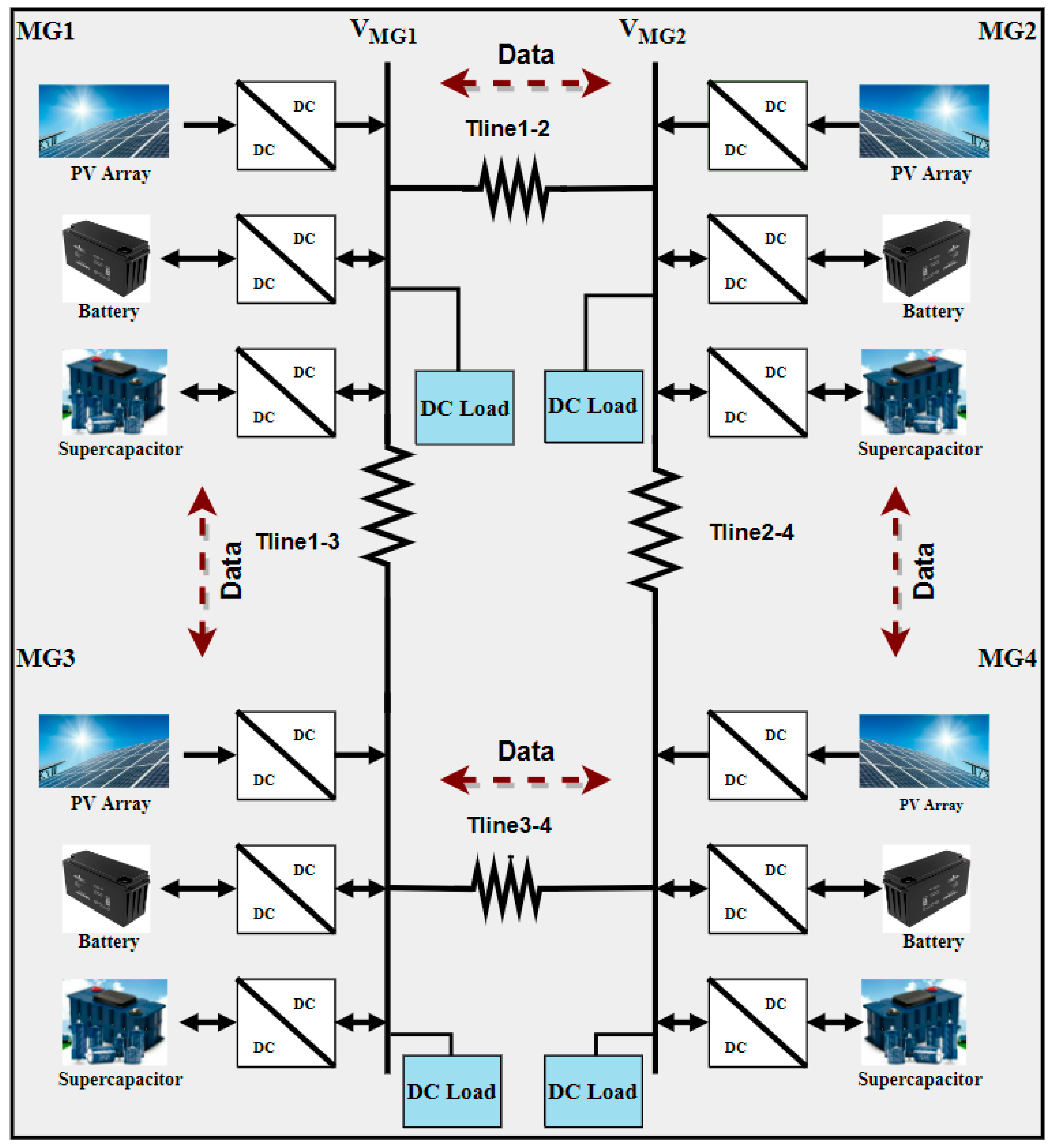
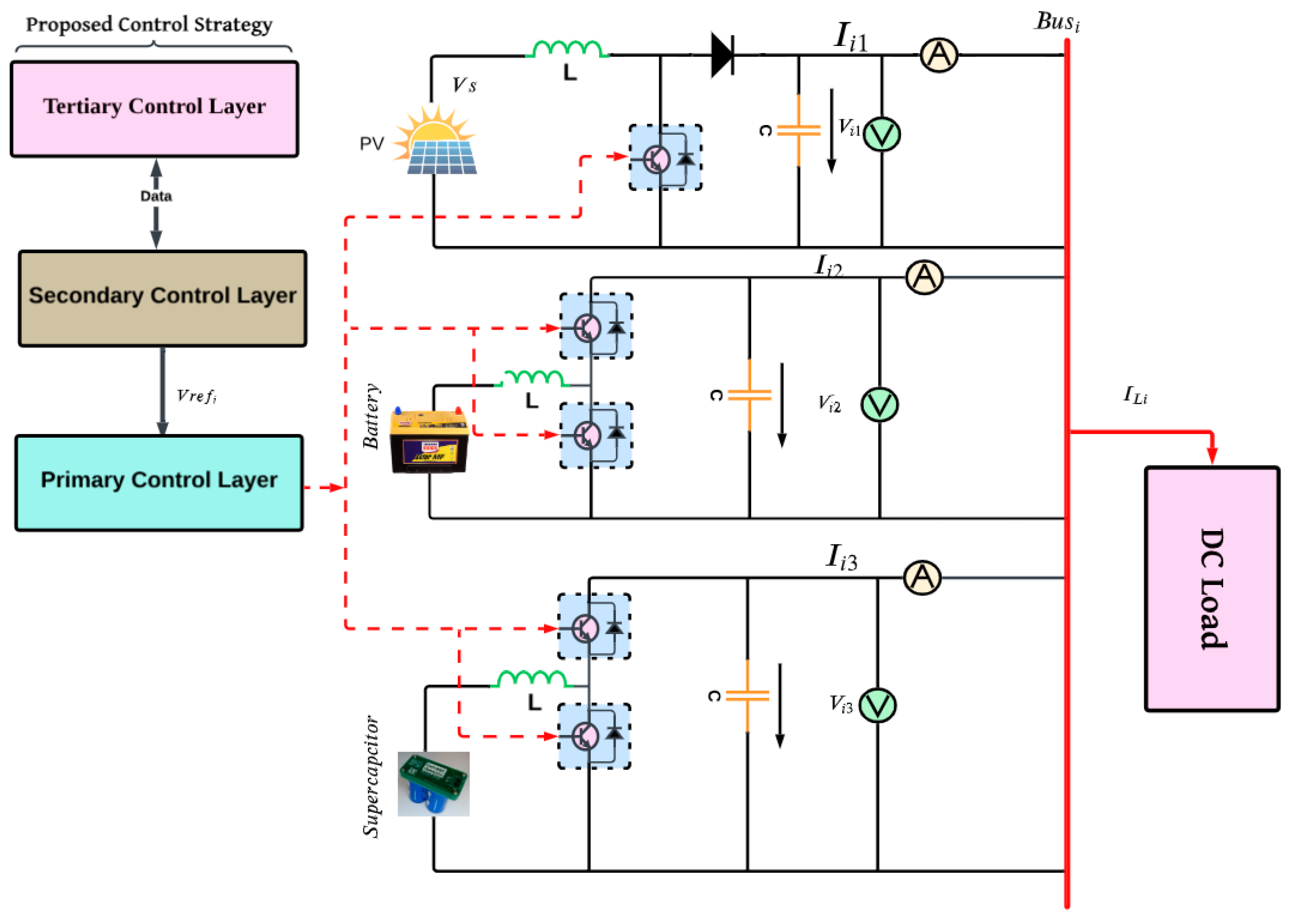
A MGs cluster is defined as a network of interconnected MGs designed to supply power to a specific region or territory. In this cluster configuration, each individual MG incorporates various Distributed Energy Resources (DERs), including Photovoltaic (PV) systems, wind turbines (WT), and Energy Storage Systems (ESSs). These resources are typically connected to a common DC bus through power electronic converters responsible for regulating the power flow between DERs and the shared DC bus [
35], as illustrated in
Figure 2. While each MG within the cluster can operate autonomously, they are interconnected through communication links. This interconnection allows for the exchange of information and coordinated operations among the MGs in the cluster [
23]. The coordination among MGs enables them to exchange power and provide mutual backup support during emergencies, thereby enhancing overall dependability and system stability. Furthermore, the integration of multiple DERs and ESSs within the cluster allows for the exploitation of diverse energy sources and storage technologies, contributing to the flexibility and efficiency of the cluster [
36].
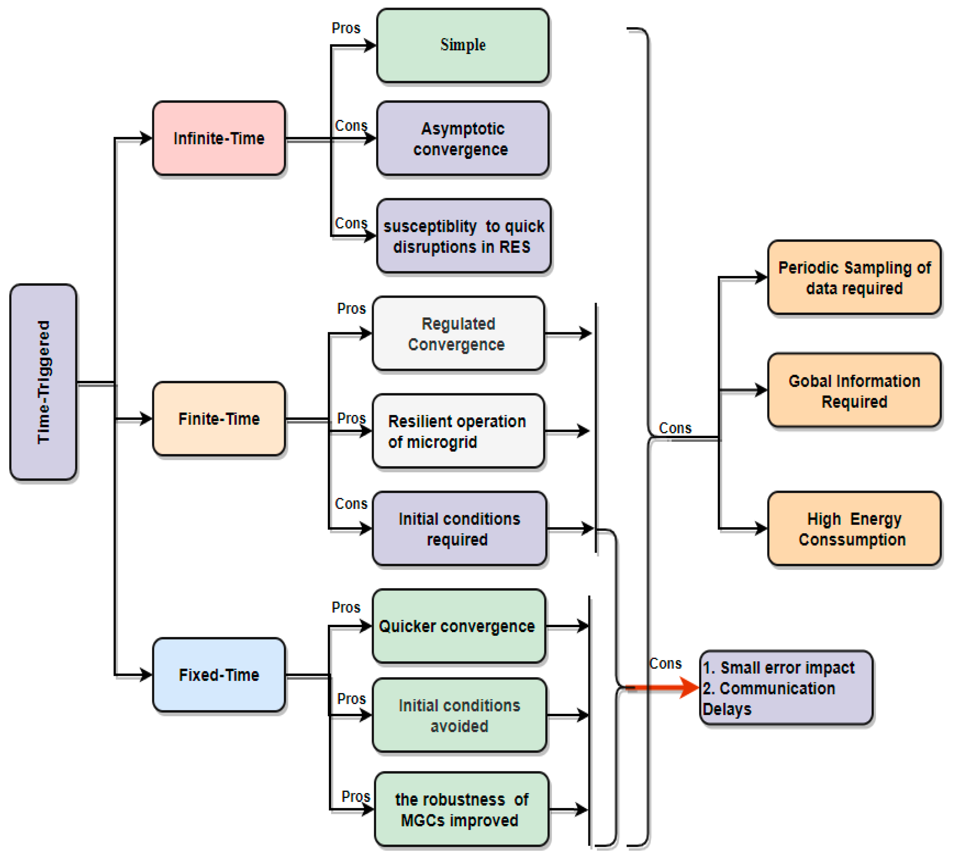
The event-triggered consensus protocol is employed to coordinate the operation of distributed systems, with a specific focus on the DC MGC in this study. Unlike fixed schedules used in conventional time-triggered control mechanisms, event-triggered protocols rely on the occurrence of “events” to prompt updates to the system’s state [
37]. The event-triggered consensus algorithm (ETC) introduces a procedure for executing control actions only when necessary, representing one of its primary distinctive characteristics [
3]. This stands in contrast to traditional time-triggered control mechanisms that enforce control actions at predetermined intervals, regardless of necessity.
In the context of ETC, the control action is triggered by an “event” indicating a change in the system’s state that surpasses a certain threshold. This change may involve alterations in the system’s inputs, outputs, or internal conditions. Once an event is identified, the control action is executed, followed by an update to the system’s state. This strategic approach has the potential to enhance the effectiveness of the control system by reducing the number of unnecessary control actions, as well as minimizing the required volume of computation and communication [
35]. Additionally, it contributes to the system’s resilience by enabling a quicker response to state changes.
4. The Main Control Objectives and Formulation
Numerous studies have been undertaken to enhance the effectiveness of MGs. These investigations primarily focus on achieving proportional current sharing among MGs within a cluster. Proportional current sharing is accomplished by distributing load currents based on the rated capacities of individual MGs. Additionally, these studies aim to regulate the overall voltage of the MG, ensuring that the average voltage converges to the rated voltage during steady-state conditions. The objectives are derived from insights inspired by [
23].
To achieve these goals, the voltage information is estimated by calculating the current error, which is then utilized to generate the reference voltage (
Vref). In this research, the same approach is applied to renewable energy sources within each MG of the cluster. A novel threshold value, tailored to the specific cluster situation, is proposed, and incorporated into Equations (1) and (2) as outlined below.
where
and
indicate the maximum capacities of
and
in MG. These capacities need to be greater than zero.
The following Equation (2) can determine the global average voltage of the MG.
which can be regulated to
in a steady state. In other words,
should be zero. Where
,
and
refer to the average voltage observer of the MG, the voltage of
, and the nominal voltage of the microgrid cluster.
Local controllers, which have been explained in [
36,
42] within each MG in the cluster need to maintain constant two-way communication with their surrounding MGs to exchange significant information. In this regard, continuous interaction is required even if the MG is operating normally. Thus, each MG’s local controller should always keep its neighbors up to date. The primary objective of the proposed control technique is to reduce the amount of interference among neighboring MGs. Once this occurs, the MG situation will be determined by comparing the error that results from the subtraction of the actual value of the current to the latest triggering instant value of the current with the threshold of error established in this research. Thus,
will keep making use of the latest instantaneous trigger value of the neighboring MG current
which indicates that there are now no issues or load fluctuations, as explained in
Figure 4 and
Figure 5. Equation (3) describes the deduced technique for generating a voltage reference of the primary control layer for each MG.
The two parts of
need to be recalculated based on the current available at the last triggering instant.
where
refer to the last triggering instant values of DG currents. By integrating the multiplication of Equation (4) with gain control
, the current correction can be computed by Equation (5) as follows.
Another part of the voltage reference can easily be obtained by determining the locally observed voltage regulation (
that results from summing the local voltage of
and integrating the multiplication of Equation (4) with gain control
.
Therefore, Equations (5) and (9) are combined to produce the reference voltage sent to each MG’s local layer in the cluster.
refers to gain control of the voltage observer.
This equation can be used as a Lyapunov function (LF).
Current (
) can be derived from Equation (1)
The correlation between the real-time current sharing error and the event-triggered current sharing error needs to be derived as follows:
Substituting Equations (14) and (15) into Equation (4) produces
Also, Equation (16) is further organized and rearranged to get
where
which refers to the Laplacian matrix of communication topology among MGs in the cluster. By substituting Equation (19) into Equation (13), we obtain Equation (20), which is substituted into Equation (12).
With the help of inequality
, Equation (21) can be further explained as follows:
Then, Equation (23) is substituted into Equation (21) to get
By rearranging Equation (24),
can be obtained as follows:
Equation (25) shows that the threshold value of the error could be obtained as follows:
It is obvious that Equation (26) can be further organized by adding
to get
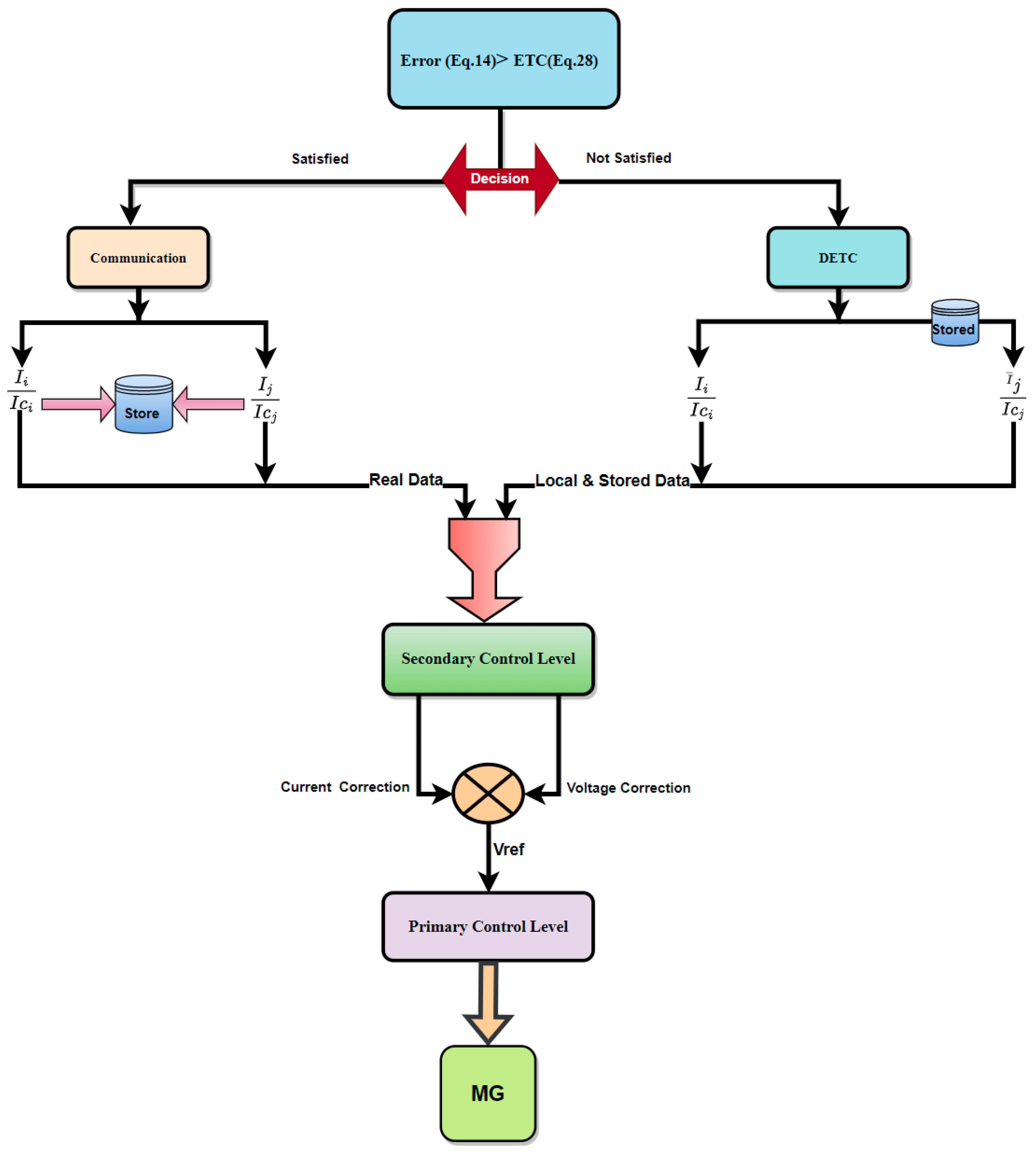
If the error value exceeds the threshold specified in Equation (28), the triggered signal is activated, and the actual current value is communicated to the controller of the MG. Conversely, if the error is less than the predetermined threshold, as defined in Equation (28), the triggered signal is disabled. It is crucial that the values of σ and b are both less than one. The proper determination of these parameters is essential, as they directly impact the convergence speed of the estimated current. The error
obtained from the differences between the actual values of MGs currents
and the current values stored from the last triggering instant (
is compared with the threshold value of error in the above equation. If it exceeds this threshold, the triggering mechanism is activated, as illustrated in
Figure 4. It is noteworthy that the inclusion of the parameter β in Equation (28) introduces a small margin for error increases, preventing the event condition from being triggered by insignificant errors and eliminating the Zeno phenomenon [
41].
This method is explained in detail in
Figure 5, which includes all control levels.
5. Results and Discussion
To evaluate the performance of the proposed control strategy under these conditions, simulations were conducted in the MATLAB environment using a four-PV and HESS MGs cluster. As illustrated in
Figure 2, the MGs were interconnected by tie-lines, modelled as comparable resistances of 1 Ω. Each MG within the cluster was equipped with PV systems, ESS units, DC–DC boost converters, and bidirectional converters to achieve a 48 V output for the connected load in each MG. The primary components of each MG are depicted in
Figure 4, and detailed specifications for each MG can be found in
Table 1 and
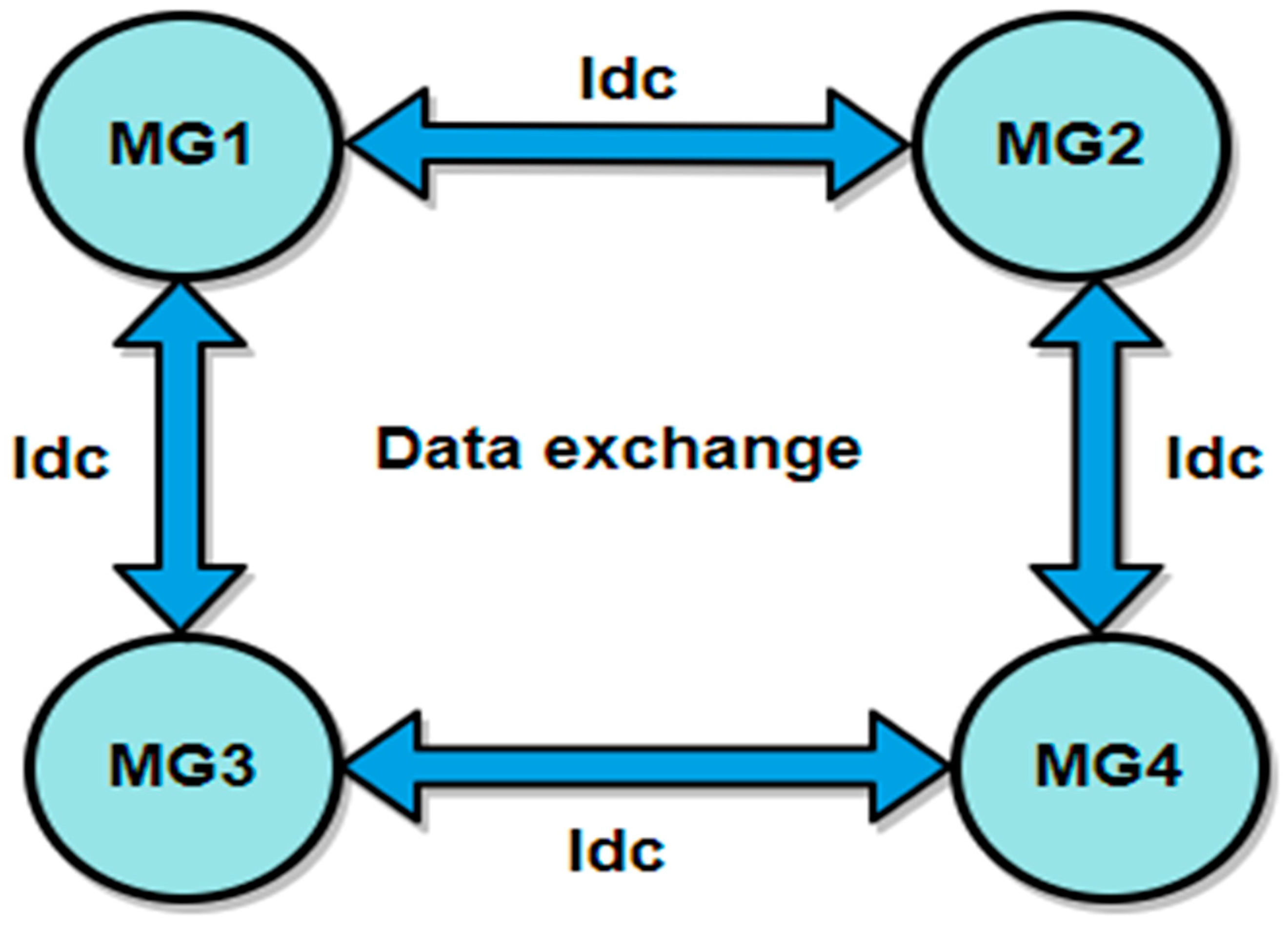
Table 2. These simulations aim to provide a comprehensive assessment of the proposed control strategy’s effectiveness in a practical context. The core feature of this new control method is that the MGs’ controllers exchange the current information among them while the voltage information is determined based on the current errors and local voltage of MGs, resulting in a reduction in communication stress in comparison with previous research. Based on this connection, the Laplacian matrix (
is constructed as follows:
Figure 6 illustrates the structure of each MG within the cluster. Local measurements of voltage and current, along with the reference voltage obtained from the tertiary control level, were integrated into the primary control layer’s voltage and current control loops to achieve the primary control objectives.
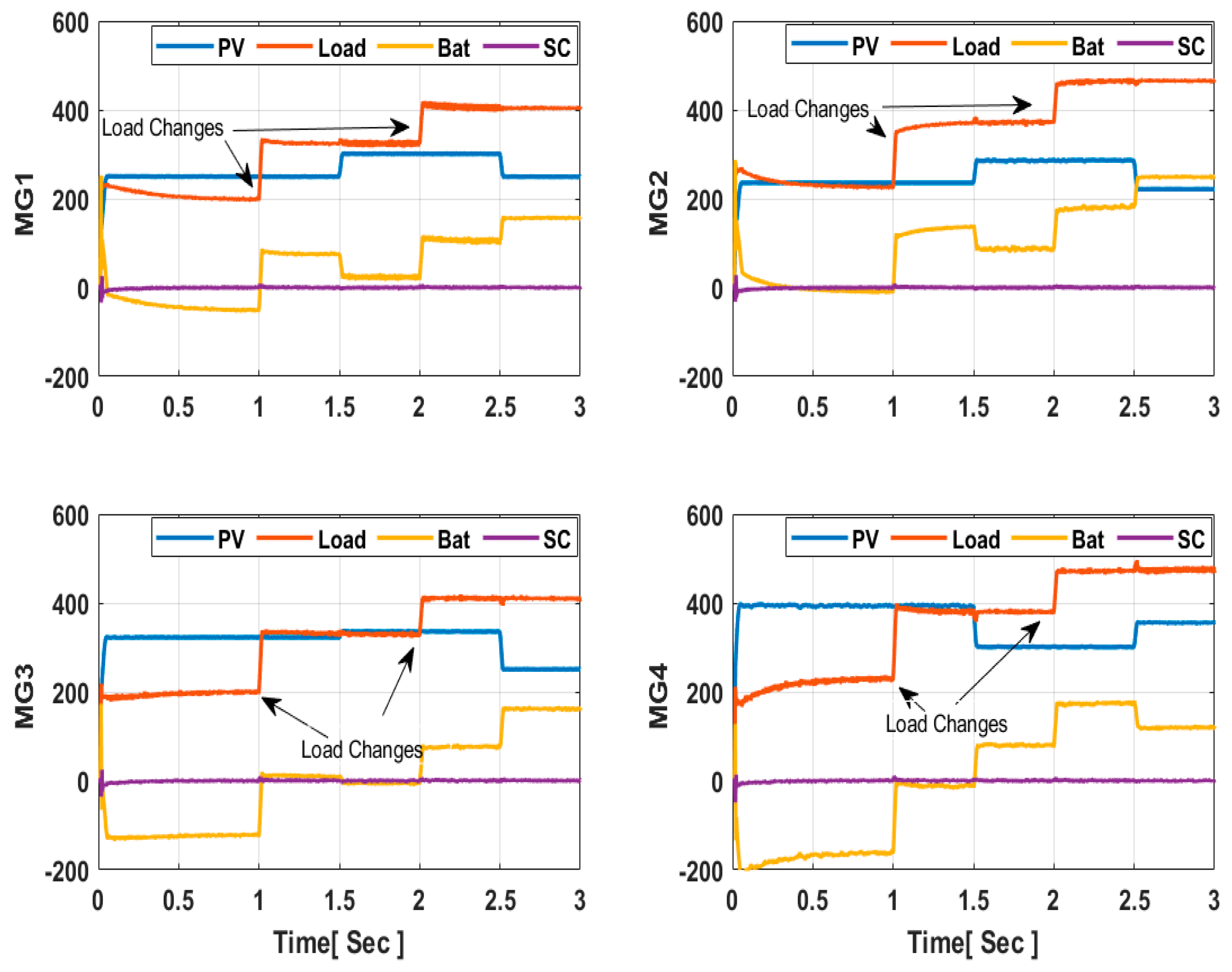
In this study, the rated currents of MGs were set to 14 A, 16 A, 14 A, and 16 A, respectively, with corresponding load resistances of 8 Ω, 10 Ω, 12 Ω, and 14 Ω (resulting in a total load of 854 W) and a standard voltage of 48 V for each MG in the cluster. Additionally, the PV generation varied for each MG, as outlined in
Table 2. Despite the variations in both load and PV generation, power-sharing converged to their equilibrium set points within 0.5 s, as depicted in
Section 5.1. This affirms the resilience of the proposed control strategy in achieving accurate power-sharing among participating MGs in the cluster, resulting in reduced power dissipation. Thus far, the results have demonstrated the reliability of clustered MGs in meeting the system’s power requirements.
To further assess the cluster’s performance, its functionality needs to be investigated under various operating scenarios, including load variations and faults. These aspects are addressed in the following subsections.
5.1. The Load Changes Scenario
In the given scenario, the simulated cluster depicted in
Figure 2 has been subjected to simultaneous load changes and solar irradiance fluctuations. Specifically, the load resistances of each MG in the cluster have been reduced at 1 s and 2 s, resulting in an overall increase in power to 1258 W and 1337.38 W, respectively as outlined in
Table 3. Concurrently, there are fluctuations in PV generation, as outlined in
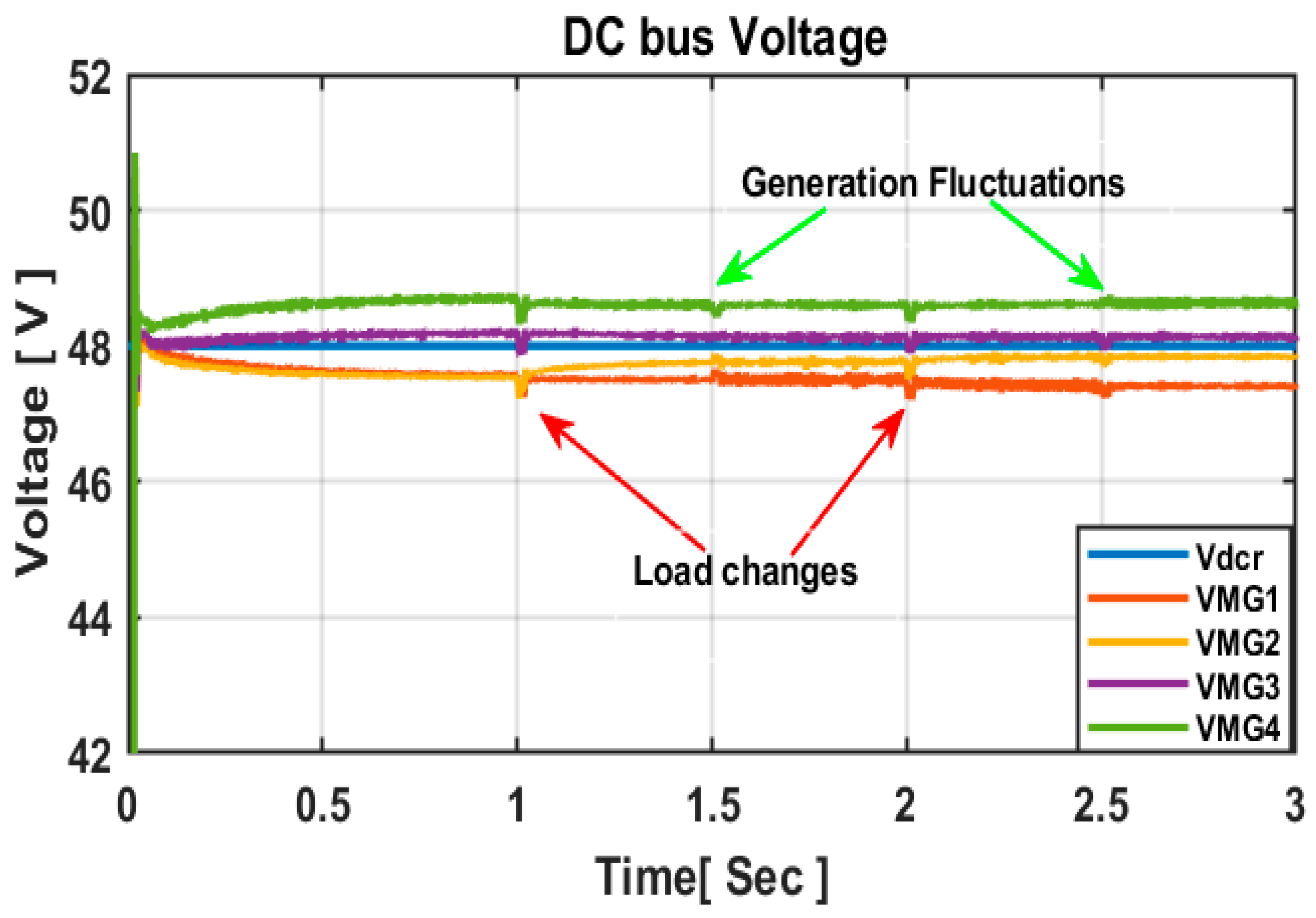
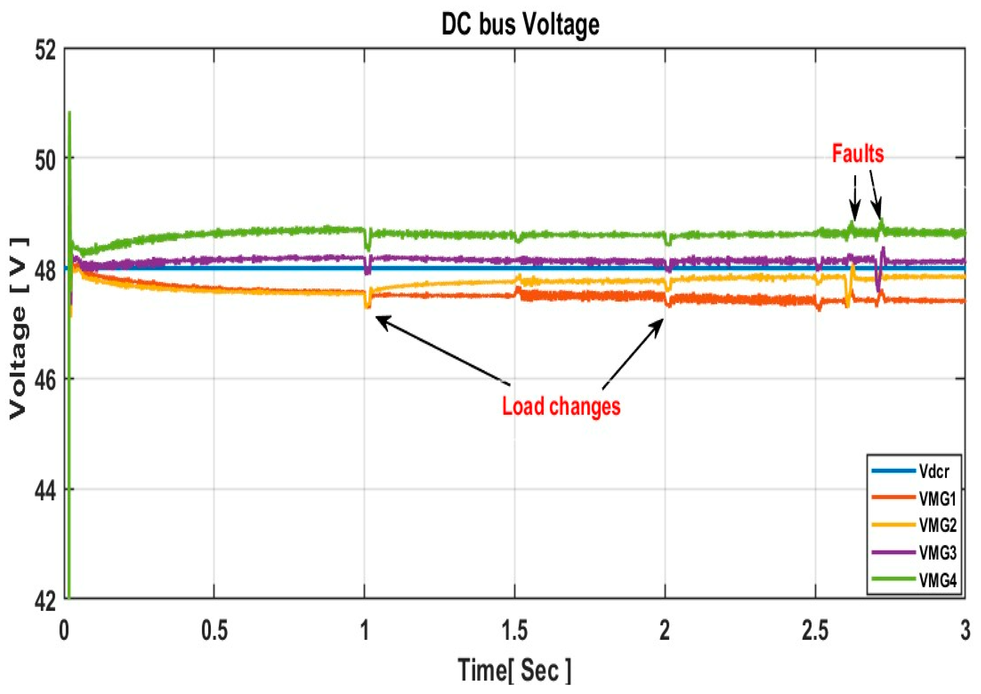
Table 4. The control method successfully maintains the MGs’ local DC voltages at 48.34 V, 47.85 V, 47.225 V, and 47.24 V, respectively as shown in
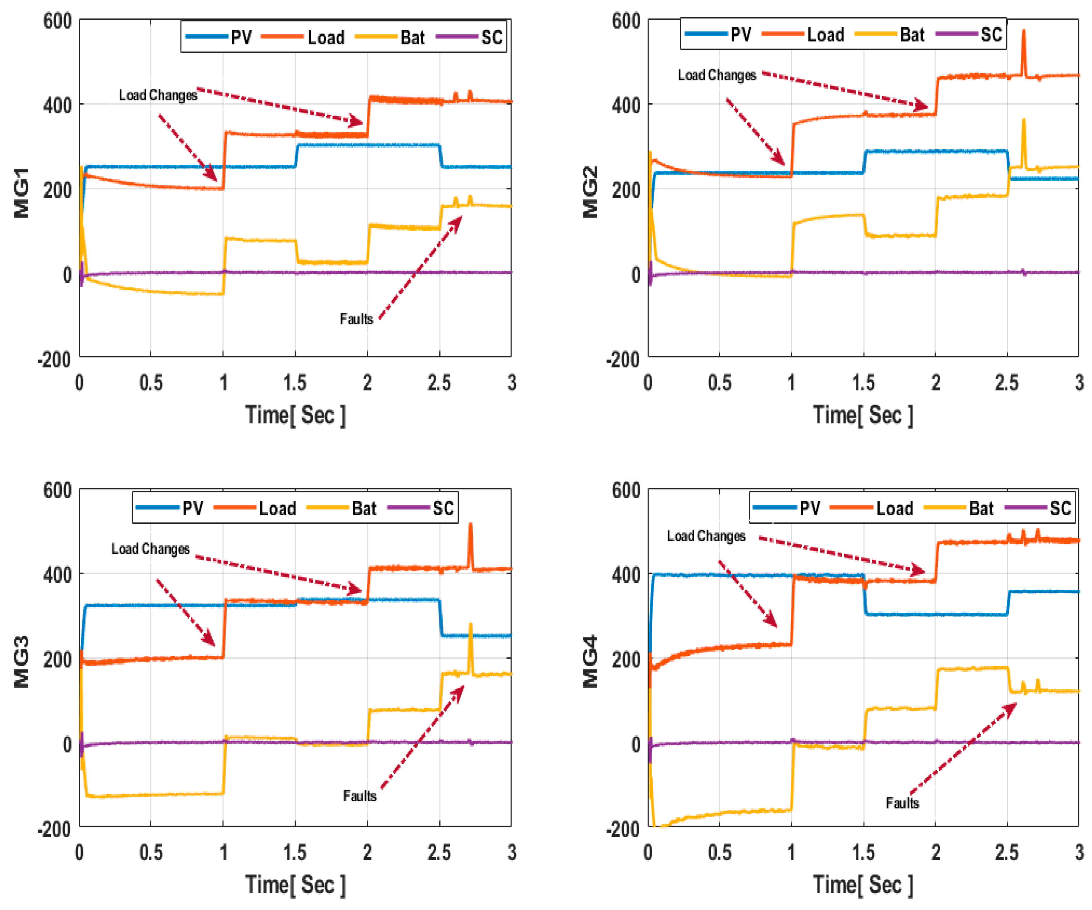
Figure 7. Precise power sharing between the PV and HESS components has been achieved in each MG, as depicted in
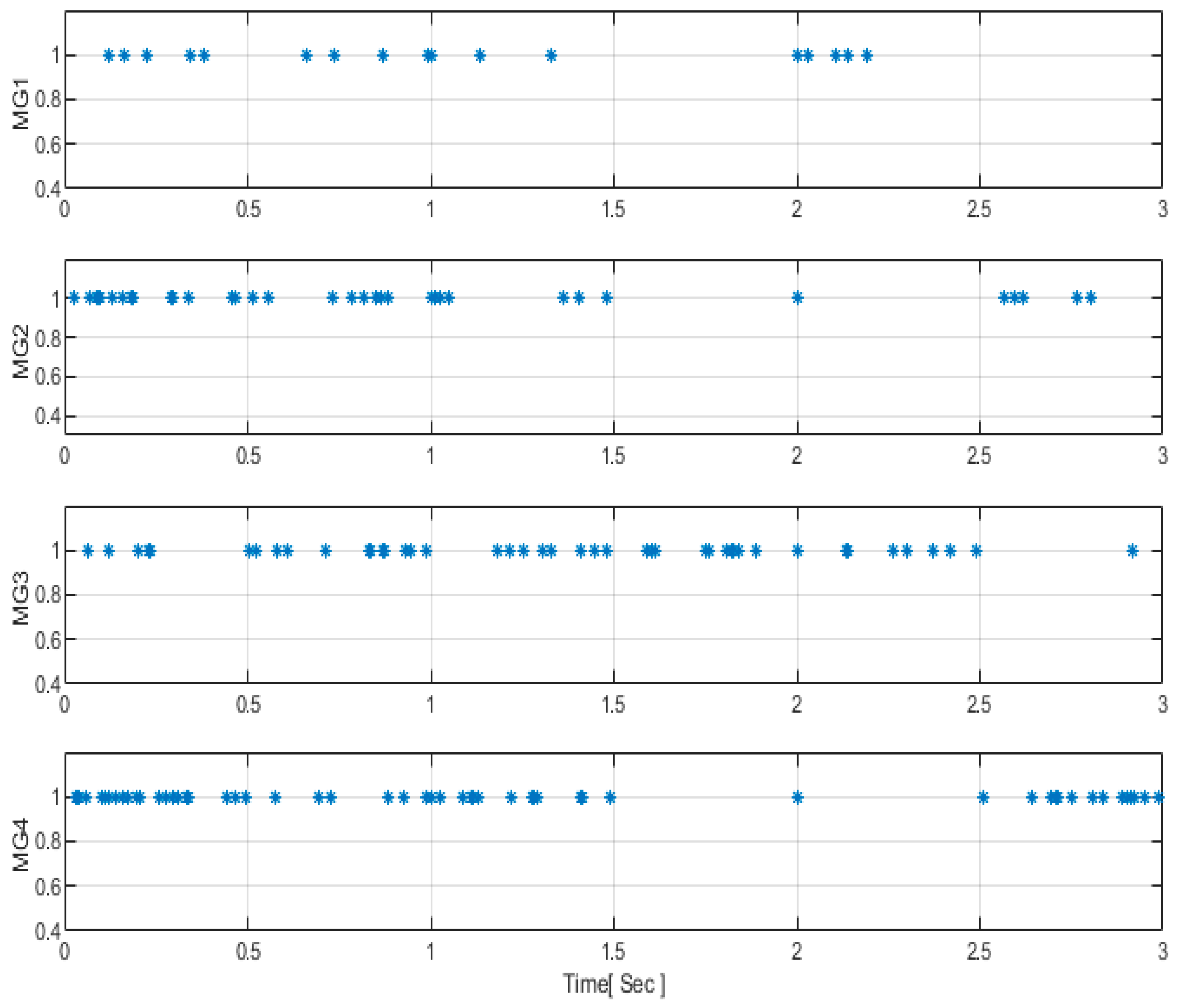
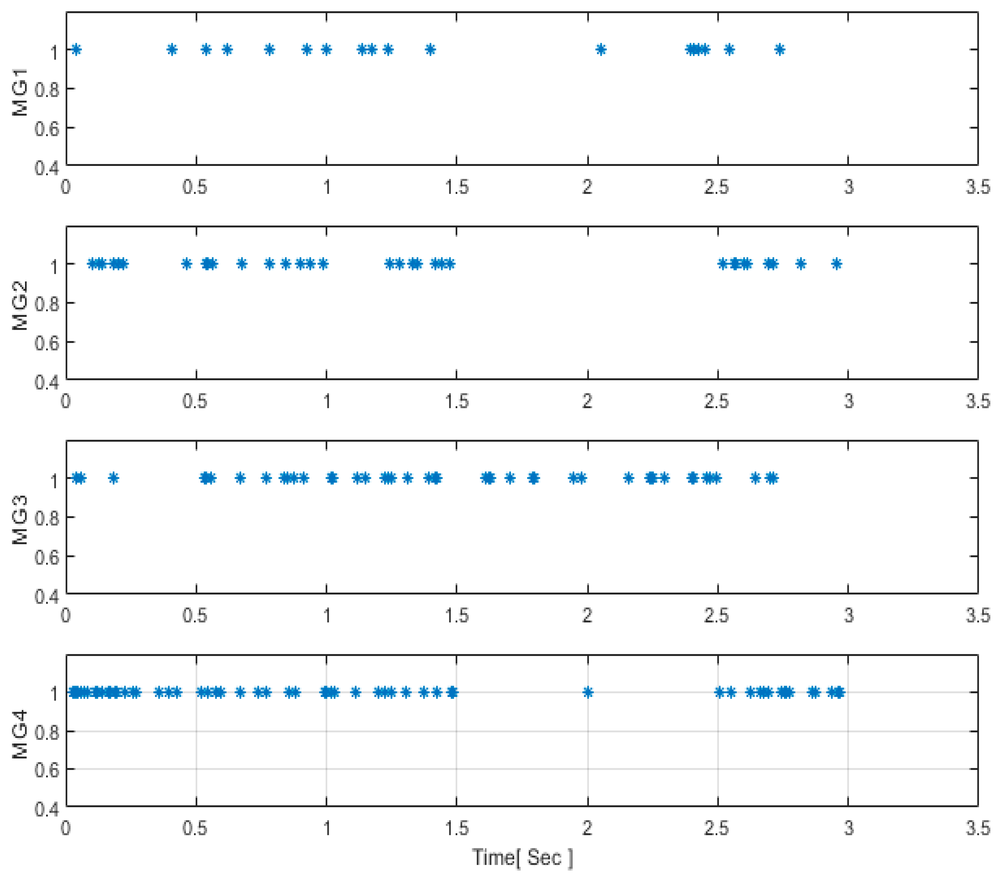
Figure 8. Notably, MGs with the same rated powers converge to their equilibrium points within 0.54 s. During load variations at 1 s and 2 s, batteries and supercapacitors exhibit robust responses, effectively meeting the increasing demand in instances of reduced PV generation within the cluster, leading to minimal power loss. Moreover, the number of instances triggering events has significantly decreased, as illustrated in
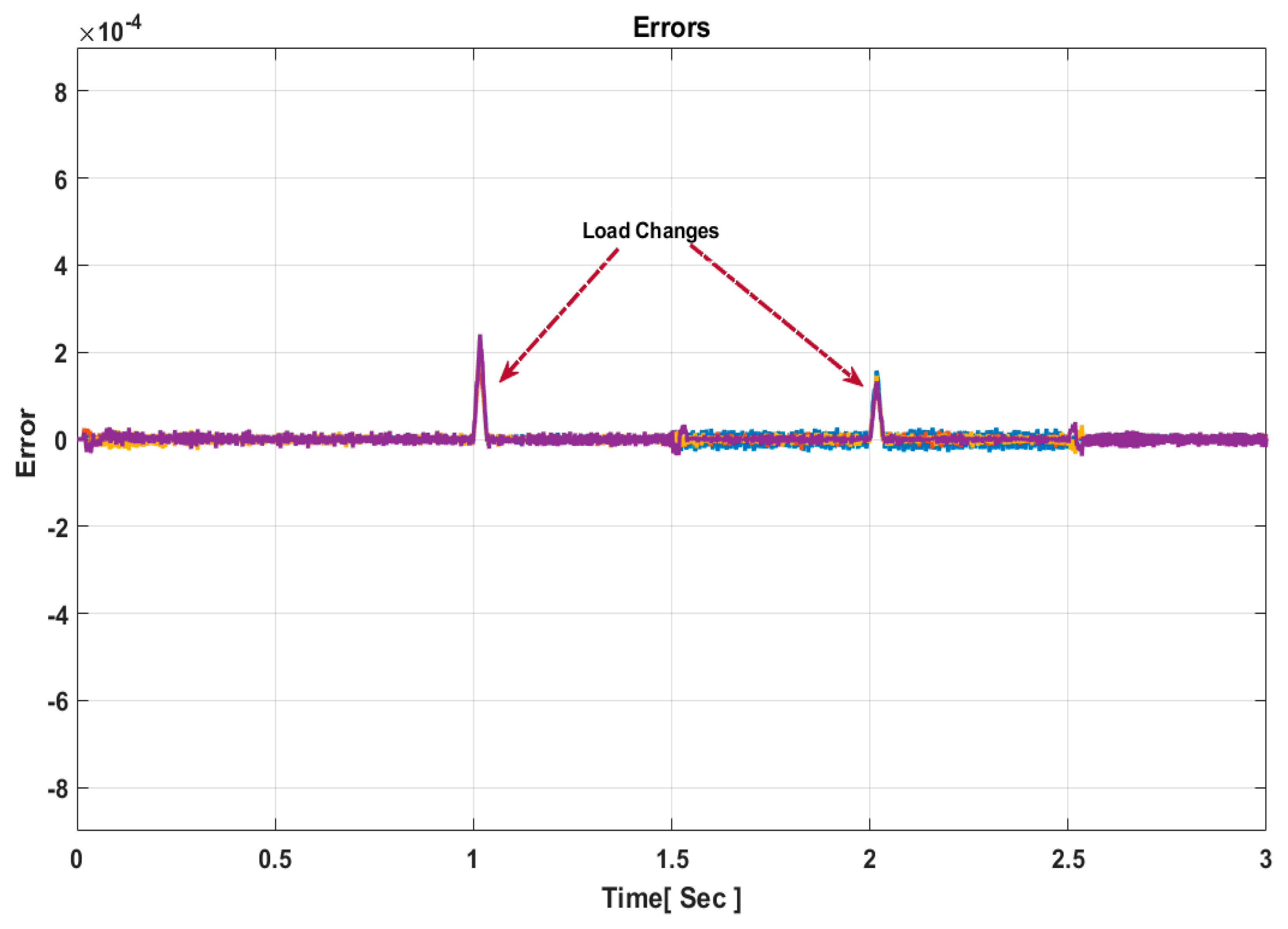
Figure 9. This observation is crucial, emphasizing that the system’s error remains minimal and does not surpass the predefined threshold stated in Equation (28), except during specified instances when load changes occur at these periods. Consequently, the event-triggered consensus technique is sensitive primarily to significant changes, such as load variations, and remains unaffected by minor errors, as demonstrated in
Figure 10.
Figure 7,
Figure 8,
Figure 9 and
Figure 10 provide a visual representation of the performance of the proposed control approach. The results demonstrate that the control strategy successfully maintains acceptable voltage regulation for all clustered MGs within a specific range (0.716% to 1.615%). Moreover, it achieves a precise power distribution across MGs in the cluster, contributing to the stability and efficiency of the system. An additional benefit is the reduction in unnecessary communication exchanges among neighboring MGs, effectively minimizing data congestion, as illustrated in
Figure 10.
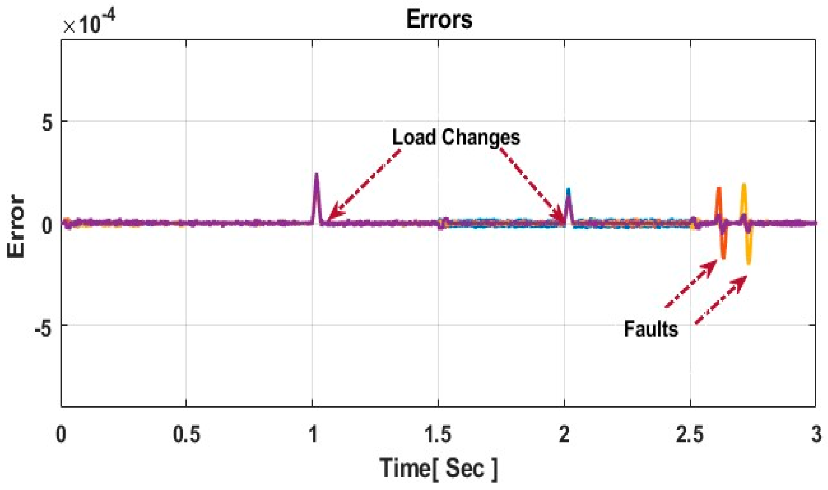
5.2. Load Changes and Fault Scenarios
The results under fault and load change conditions demonstrate that the proposed control technique effectively manages and mitigates the impact of multiple disturbances occurring simultaneously in the MGC. The simulation results reveal that the DC bus voltages remain within the standard limit (47.27 V, 47.36 V, 48.04 V, and 48.48 V, respectively) at 2.6 s and 47.27 V, 47.28 V, 47.56 V, and 48.48 V, respectively, at 2.7 s as illustrated in
Figure 11. The convergence of powers is achieved within a range of 0.5 s to 0.54 s, ensuring accurate power sharing among the participating MGs in the cluster
Figure 12.
Additionally, it was observed that the HESS exhibits robust responses, effectively meeting the increasing demand in instances of reduced PV generation within the cluster, leading to a reduction in power loss. Furthermore, the results indicate that the triggering instants for data sampling and transmission are low and not sensitive to minor errors in the system. This is evident from the significant reduction in the number of data transmissions, decreasing from 14,000 times using a time-triggered consensus mechanism to just a few times (1344) with a sampling instant of one millisecond. This underscores the effectiveness of the presented event-triggered strategy in reducing unnecessary data exchange while ensuring proper system performance.
The performance of the presented control approach in triggering situations is elucidated in
Figure 9 and
Figure 13. It is noteworthy that MGs do not need to exchange their current information during steady-state circumstances, as the errors (
E) resulting from the difference between the actual values of currents and the last triggering instants in the system do not exceed the threshold value of current (TVC) stated in Equation (28). This reduction in errors minimizes unnecessary data exchanges among MGs in the cluster. However, the controllers of MGs are triggered when
E exceeds TVC, especially at 1.5 s and 2.5 s, when load changes occur, as shown in
Figure 10. Additionally, these controllers are activated to exchange data during faults in the cluster, as explained in
Figure 14. In general, the number of triggering instants in the figures mentioned earlier was 1344, which is less than [
25,
41,
43] and classical control approaches (14,000 times) in the literature. In addition to the number of triggering instants, a fast voltage recovery within 0.02 s after sudden changes at 1 s and 2 s was achieved, as shown in
Figure 9, and in this case it could be faster than the voltage recovery in [
25]. Also, power sharing among PV and HESS is close to 100%, which implies there were no power losses. This validates the robustness of the proposed control approach under critical working situations, as illustrated in
Figure 15.


