Article

Adaptive Control Approach for Accurate Current Sharing and Voltage Regulation in DC Microgrid Applications

1
Faculty of Technology and Education, Sohag University, Sohag 1646130, Egypt
2
Electrical Engineering Department, College of Engineering, Sohag University, Sohag 1646130, Egypt
3
Department of Electrical Engineering, Assiut University, Assiut 71516, Egypt
4
Department of Electrical Engineering, College of Engineering, King Khalid University, Abha 62523, Saudi Arabia
5
Department of Industrial Engineering, College of Engineering, King Khalid University, Abha 62523, Saudi Arabia
6
Electrical Engineering Department, Faculty of Engineering, Minia University, Minia 61111, Egypt
*
Author to whom correspondence should be addressed.
Energies 2024, 17(2), 284; https://doi.org/10.3390/en17020284
Submission received: 14 November 2023 / Revised: 1 January 2024 / Accepted: 3 January 2024 / Published: 5 January 2024
(This article belongs to the Section F: Electrical Engineering)

Abstract

:
A DC microgrid is an efficient way to combine diverse sources; conventional droop control is unable to achieve both accurate current sharing and required voltage regulation. This paper provides a new adaptive control approach for DC microgrid applications that satisfies both accurate current sharing and appropriate voltage regulation depending on the loading state. As the load increases in parallel, so do the output currents of the distributed generating units, and correct current sharing is necessary under severe load conditions. The suggested control approach raises the equivalent droop gains as the load level increases in parallel and provides accurate current sharing. The droop parameters were checked online and changed using the principal current sharing loops to reduce the variation in load current sharing, and the second loop also transferred the droop lines to eliminate DC microgrid bus voltage fluctuation in the adaptive droop controller, which is different and inventive. The proposed algorithm is tested using a variety of input voltages and load resistances. This work assesses the performance and stability of the suggested method using a linearized model and verifies the results using an acceptable model created in MATLAB/SIMULINK Software Version 9.3 and using Real-Time Simulation Fundamentals and hardware-based experimentation.

1. Introduction

DC microgrids are gaining popularity in many power DS due to significant advantages such as improved efficiency, dependability, and stability as compared to AC microgrids. DC-based energy sources, such as photovoltaics and storage units, require considerable usage of power electronics-based interface devices to be integrated. power conversion steps, increasing overall efficiency and reliability. Other key considerations driving the future rise of DC microgrids are a lack of reactive power, lower transmission loss, and lower costs due to the elimination of power conversion steps. Aside from harmonic difficulties caused by the high penetration of nonlinear loads in a power distribution network, DC microgrids are regarded as a superior alternative to AC microgrids. DC microgrids, on the other hand, are easier to build and have greater power control. The expansion of DERs, coupled with electronic loads, electric vehicles, and energy storage systems in the microgrid system, has pushed the widespread use of the DC-based distribution system. The growing popularity of a DC microgrid system is due to its contribution to loss reduction, cost reduction, increased power transmission capability, system safety improvement, power quality improvement, devaluation of electromagnetic interference, and easy integration of modern electronics loads [1]. The DC microgrid can be operated in grid-connected mode, where the grid is linked to the DC bus to deliver power deficits or absorb surplus power, or in islanded mode, where the DC microgrid works independently and autonomously without grid synchronization [2]. Many of the new loads are electronic direct current (DC). A microgrid is made up of many parallel-connected converters that transmit current across various distributed resources over a single DC bus, as demonstrated in Figure 1. DC microgrids are free from frequency concerns; hence, control loop analysis and design may be simpler [3].
Achieving efficient and reasonable output voltage regulation for the current shared across the converters. The primary purpose of current sharing control of multi-converters in a DC microgrid [4]. The main challenges in microgrid control stem from uncertainties in renewable power sources, such as wind and solar energy, due to intermittent power generation, uncertainties in load demands and schedules, and uncertainties in the distributed topology of power sources that are spatially scattered due to location and size constraints. Given these limitations, a robust and distributed control solution is required for the reliable functioning of smart microgrids. It is challenging to satisfy the robustness and performance objectives in the traditional proportional-integral differential equation in the multiple-input multiple-output environment dictated by the need to govern various generation sources [5,6].
Due to line resistances and non-identical converters, droop management is a compromise between output voltage regulation and current sharing between converters. When the variances in output currents are small, a high amount of Droop Gain will degrade voltage regulation. Low droop gain enables good regulation, but the output current sharing variations are significant. As a result, primary control focuses on equal current sharing while maintaining a high droop gain. An extra secondary controller then improves the voltage regulation [7]. Droop can only function if the droop parameters are sufficiently large concerning the line resistances. However, large droop parameter values result in unacceptable low voltage levels. As a result of this, there is a compromise between these objectives [8,9]. Many papers have presented control approaches to improve load sharing through droop management. One of them is the Gain Scheduling Droop. The connection between droop gain and load power is linear. Droop gain is altered dynamically as the load power changes in this technology [10]. The adaptive droop approach is used to build the principal control for each unit solely by utilizing local electrical parameters, which may reduce both the control structure complexity and communication reliance in a practical power system. Because droop controllers do not need a communication system and can prevent single points of failure, they are the primary control strategy used to maintain appropriate parameters for the microgrid, ensuring the system operates steadily and dependably [11].
Control systems based on communication, such as centralized, master–slave, circular chain, distributed, and hierarchical, give optimal power sharing and voltage regulation performances [12]. They do, however, necessitate costly communication networks that are prone to failure and reduce system reliability, flexibility, modularity, and expandability. As a result, communication-based control techniques are more suited for use in DC microgrids with fixed and compact structures [13].
Power sharing among DERs is enabled by non-communication-based control techniques that use locally monitored bus voltages [14]. They have several advantages, including ease of installation, low cost, great modularity, flexibility, expandability, and reliability [15]. Control solutions that do not rely on communication systems are therefore better suited for use in some of the upcoming DC microgrids with numerous geographically distributed DERs. Conventional droop control, enhanced droop control, DC bus signals, and mode-adaptive droop control schemes are all examples of non-communication-based droop control strategies [16].
The basic purpose of DC microgrid control is to provide effective and acceptable output voltage regulation values for the current shared across the converters [17]. Line impedance has a significant impact on the performance of conventional droop. The droop control method can be used in both a linear and non-linear mode [18]. The non-linear droop mechanism was chosen due to the negative effect of line impedance on the linear droop mechanism. The non-linear properties of droop control have been seen to delay the trade-off between voltage regulation and current sharing [19]. Because of improved communication and faster data transmission among converters, the distributed control technique can conduct adaptive droop control at the secondary and primary control levels [20]. The adaptive droop gain approach allows for the soft adjustment of the droop coefficient under various loading conditions. The voltage and current regulators are implemented at the secondary level to offer voltage and impedance correction terms [21,22]. To reduce the variation in the load current sharing, the droop parameters were checked online and changed utilizing the principal current sharing loops [23,24].
The second loop additionally shifted the droop lines to eliminate the DC microgrids’ bus voltage fluctuation [25]. The main loop is used to continually update the value of the virtual resistances in the preceding section, ensuring that all converters in DC microgrids share load correctly [26,27]. This study presents a novel adaptive control strategy that, depending on the loading state, meets accurate current sharing and suitable voltage regulation for DC microgrid applications. The accuracy of the current sharing process is unimportant when there is little to no load and the dispersed generator units’ output currents are much below the upper limits. Under heavy load conditions, proper current sharing is necessary because the output currents of the dispersed generating units grow as the load does. The suggested control approach raises the equivalent droop gains as the load level increases and provides accurate current sharing. The adaptive droop controller, which is original and inventive, to do this, the droop parameters have been checked online and changed using the principal current sharing loops to reduce the variation in load current sharing and the second loop also transferred the droop lines to eliminate DC microgrid bus voltage fluctuation. The proposed algorithm is tested using a variety of input voltages and load resistances. The model is stepped by MATLAB/SIMULINK using a computed time vector and a step change in the input voltage and load, from 10 to 5 and 3.33. having a relationship, The OPAL-RT OP4510 Real-Time Simulation workflow commences with instantaneous simulation and testing, followed by a link to the DSOX3034A Oscilloscope serial trigger and analysis, segmented memory, and mask testing at any given time. A range of input voltages and load resistances are used to test the suggested method. to show how well the proposed method performs in comparison to the primary droop control. To verify the precision and efficacy of the recommended control strategy, the pertinent model is built in MATLAB/SIMULINK and utilized in hardware-based experiments and Real-Time Simulation Fundamentals.
The basic goals of this research project can be summarized as follows:
  • Investigating the primary challenges with the parallel DC-DC converters of classic droop control in DC microgrids;
  • Parallel DC-DC converter design and management for stand-alone application;
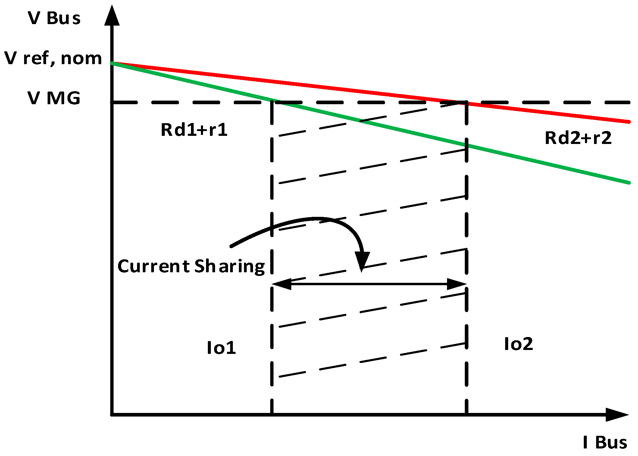
  • A simple and adaptive droop control solution is proposed to eliminate bus voltage variation and circulating current between converters with equal load current sharing.
The primary goals of this research project are to eliminate bus voltage variation and circulate current across converters while sharing equal load current [28].
The technique and results further show that the proposed enhanced adaptive droop control strategy:
  • Effectively maintains power balance in the microgrid under major disturbances;
  • Accurately regulates DC bus voltages under diverse operational situations and increases electricity sharing;
  • Increases the stability of the DC microgrid and its dynamic response to disturbances;
  • Improves DC microgrid dependability, flexibility, modularity, and scalability.

2. Materials and Methods

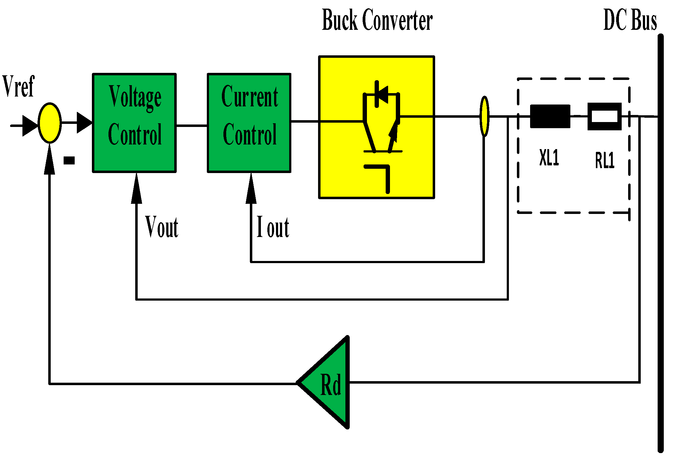
2.1. Buck DC-DC Converter Configuration System in a DC Microgrid

This section analyses variable load sharing in DC microgrids as well as recently discussed challenges. Figure 2 illustrates a DC microgrid in a parallel arrangement composed of DC-DC converters, a shared changeable load, and variable input voltages vs. As an interface converter, a DC-DC buck converter is employed between the source and the low-voltage DC bus.

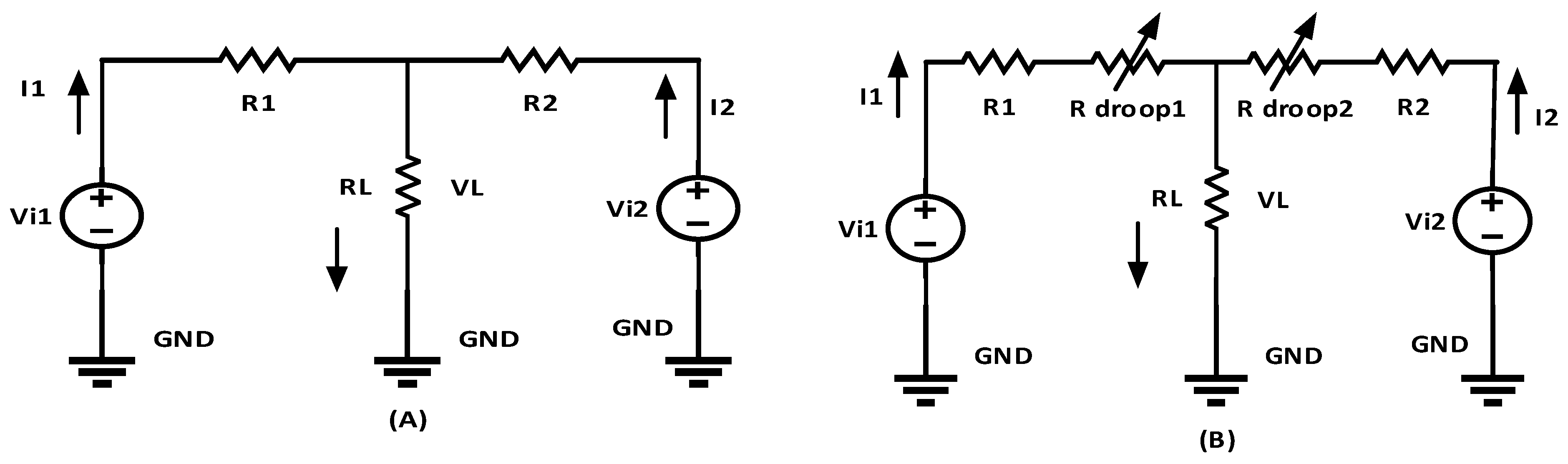
2.2. Formatting of Mathematical Components

The output current of the converter may be calculated by Equations (1) and (2):
I 1 = R 2 V i 1 R L ( R 1 + R 2 ) + V i 1 V i 2 ( R 1 + R 2 )
I 2 = R 1 V i 2 R L ( R 1 + R 2 ) + V i 2 V i 1 ( R 1 + R 2 )      
The relationship between nominal voltage and circulating current is described by the equations below [29]:
I C 12 = I C 21 ,           I C 12 = V i 1 V i 2 ( R 1 + R 2 )
The circulating current is described by the equations below:
I C 12 = I C 21 = V i 1 V i 2 ( R 1 + R d r o o p 1 + R 2 + R d r o o p 2 )
However, in performing, this is not feasible. To achieve the necessary load sharing, the reference voltage of each converter can be modified. R Droop, a fictional resistance, is employed to modify the reference voltage of each converter to do this. The corresponding equations can be written as
V DC new = V 1 ref = I 1 R 1 + R d r o o p 1 + R L I L
It can be shown that the reference voltage can be changed by varying the R Droop value using Equations (5) and (6):
V DC new = V 2 ref = I 2 R 2 + R d r o o p 2 + R L I L
This demonstrates that the necessary current sharing may be achieved by varying the value of the droop resistance by Equation (7):
I = V r e f V B u s R d + r
The revised voltage reference for the converter in droop control is as follows, based on (8):
V = V r e f R d I
The following is a discussion of how two converters share the current load resistance by Equation (9):
Δ I 12 = R d 2 + r 1 V r e f V B u s R d 1 + r 1 V r e f V B u s R d 1 + r 1 R d 2 + r 2
The droop settings must be fine-tuned to regulate the source converters and raise the bus voltage such that the output voltage of each converter is the same by Equation (10):
V * = V r e f ( R d ± Δ R ) I
At  V d i f f e r e n c e = V d c 1 V d c 2  is a positive value,  V O 1 > V O 2 > R d 2 > R d 1 I O , 2 < I O , 1 , then the following value for Rd droop is provided by Equation (11):
R d 1 , n e w = R d 1 , o l d ± Δ R
At  V d i f f e r e n c e = V d c 1 V d c 2  is a negative value,  V O 1 < V O 2 > R d 1 > R d 2 I O , 1 < I O , 2 , then the following value for Rd droop is provided by Equation (12):
R d 1 , n e w = R d 1 , o l d Δ R
At  V d i f f e r e n c e = V d c 1 V d c 2  is provided by Equation (13):
R d 1 , n e w = R d i , o l d
Figure 3A shows the equivalent circuit of parallel DC-DC buck converters powering a resistive load, and Figure 3B shows a similar circuit with variable droop control.
The voltage level, which uses 48 V and is the best option for the output low voltage DC transmission system, is an important aspect in determining system efficiency. Table 1 shows the parameters of DC-DC buck converters when examining the converters supplied with two different source voltages, Vi1 and Vi2, as well as source currents, I1 and I2.
The main source of current flowing between DC sources is the converter’s output voltage fluctuation. Figure 3A demonstrates the parallel equivalent circuit; the cable resistor product can be ignored in comparison to the high load resistance RL. As a result, the output current of the converter may be calculated [29,30,31,32].
Because of the difference in current sharing caused by circulating current, the converters get overloaded. These two implications will reduce the system’s effectiveness. The DC grid voltage level is expected to be 48 V in this work. The optimal low-voltage LV DC distribution system voltage is 48 V, which is commonly utilized in the telecommunications industry.
It should be remembered that Rd is a virtual value that can be adjusted to affect the current flow from the dispersed resources. This demonstrates that the necessary current sharing may be achieved by varying the value of the droop resistance.

2.3. Conventional Droop Control

In this design, as illustrated in Figure 4, r and L represent the equivalent line resistance and inductance from the distributed resources to the load bus, respectively, Vref represents the voltage source reference, and Rd represents the droop resistance.
Where I1 and I2 are the load currents, r1 and r2 are the equivalent line resistances connecting each power converter to the load, and Rd1 and Rd2 are the droop resistances, as seen in Figure 5.

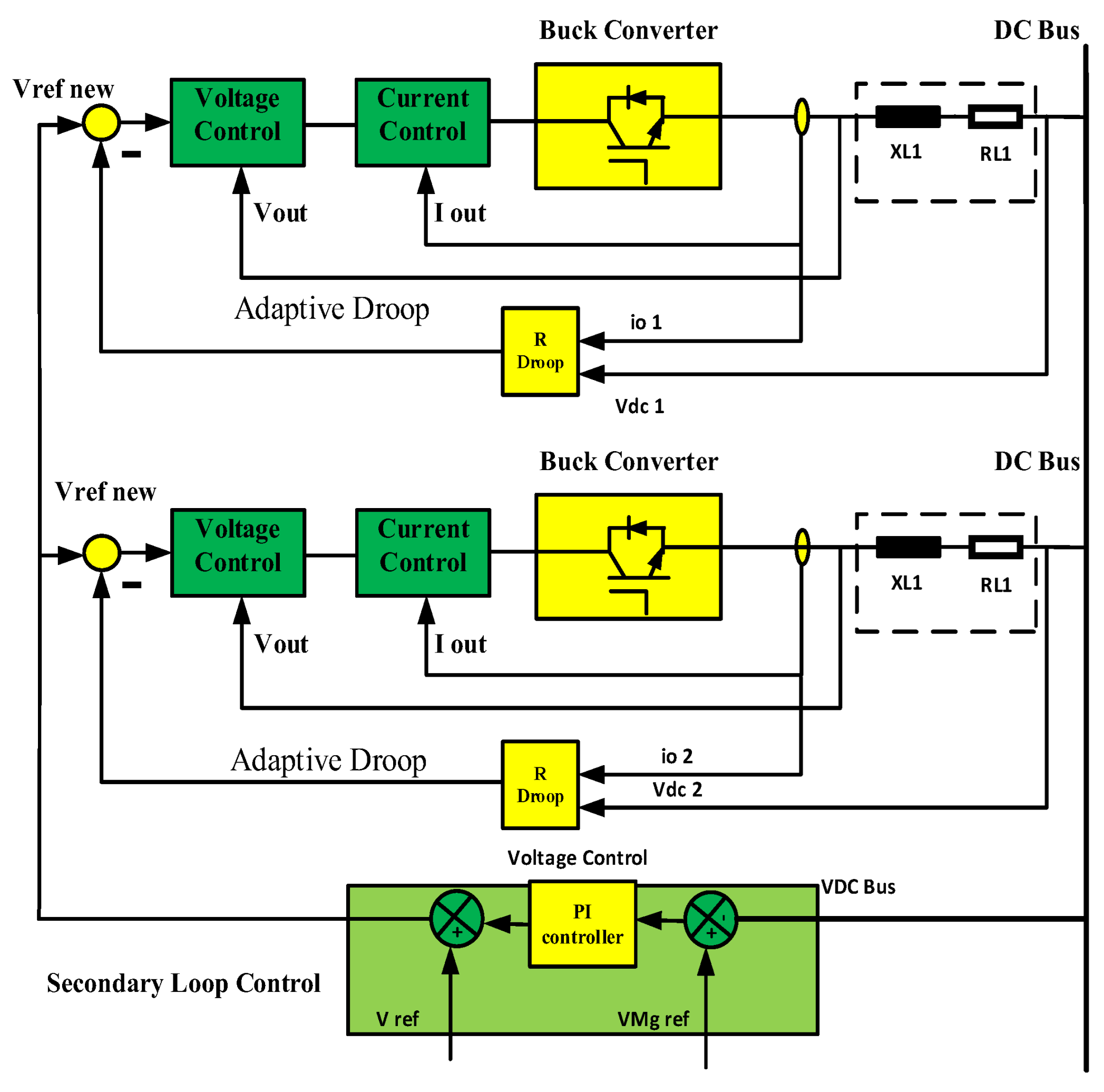
2.4. Adaptive Droop Control in DC Microgrid Strategy

The proposed adaptive control system for DC microgrids block diagram is displayed in Figure 6. The current-sharing accuracy is maximized by matching the converter’s nominal voltage. To achieve the exact current sharing error, the nominal voltage of each converter is modified using local control. Converters with lower nominal and maximum voltage deviations distribute current values more evenly. Because of the bus voltage variance and current load sharing, the controller is programmed to raise the nominal DC voltage [33,34,35,36]. The reference voltage for each converter is then modified to achieve this using virtual resistance. R Droop, the reference voltage, and power sharing of any converter can all be adjusted by modifying R Droop, as shown by Equations (5) and (6). If the voltage deviation is small, the converter’s nominal voltage will be high. In addition to lowering the current sharing error, the low voltage converter will raise its nominal voltage in comparison to the second. The secondary loop is also used to reduce voltage variation. Each control loop is explained in detail below.
Thus, Real-Time Simulation OPAL-RT OP4510 (Europe–North America–Japan) has a significant benefit during the development and evaluation of the proposed adaptive controller for its performance when the proposed algorithm is evaluated using a variety of input voltages and load resistances, developing confidence in the power grid operator. Display of voltage and current waveforms and presentation of real results to confirm the functioning extent of the proposed control system as shown in Figure 7. A computed time vector is used by MATLAB/SIMULINK to step the model when the load is changed in steps from 10 to 5 and 3.33 ohm when the input voltage is changed. Simulink instantly computes the outputs for the next time value after calculating the previous time value, and this process continues until the stop time is reached. With reference Instantaneous Simulation Real-time simulation and testing, as well as connection with the DSOX3034A Oscilloscope serial trigger and analysis, segmented memory testing at any time, are the first steps in the OPAL-RT OP4510 workflow.

2.5. Primary Control Loop System

The primary loop’s purpose for all converters in DC microgrids is to ensure proper load sharing. The proposed adaptive droop concept is discussed using the droop diagram in Figure 5. Where Rd1 and Rd2 are the initial droop characteristic lines, with non-desired current sharing I1 and I2, and VMG is the bus voltage deviation. Adaptive control is used to relocate the droop characteristic lines to a point that meets the DC microgrid control criterion. Each movement in this work can be presented separately using two distinct stages. The initial phase is control of the adaptive current sharing. ±ΔR is added to the traditional droop Equation (8) to update the value of the virtual resistance and improve power sharing, Figure 8 illustrates a flowchart of the suggested strategy’s steps.

2.6. Secondary Control Loop System

The primary loop is used to continuously update the virtual resistance value from the previous section, ensuring proper load sharing among all converters in DC microgrids. The bus voltage’s deviation is affected by the load as well as any faults in the current or voltage feedback. Figure 9 shows how a second loop is used to compensate for the bus voltage variation caused by the DC microgrids. To restore the bus voltage to the desired value, each converter is shifted by the voltage deviation value ∆VMG.

3. Results

This paper provides a physical testing device for validating the suggested control algorithm. Simulations and analysis test procedures were performed using MATLAB/SIMULINK and Real-Time Simulation OPAL-RT OP4510 for typical cases including adaptive control activations and load changes for a 48 Vdc microgrid in islanded mode to validate the effectiveness of the proposed control algorithm. Figure 10 shows the change in the input voltage of two buck converters. Case studies were performed under varied load circumstances. The results show that the system’s objectives of current sharing between two converters and bus voltage stability have been achieved and that the system’s stability and resilience are ensured by the suggested control algorithm. The resulting modelling and practical results show that the presented technique outperforms the droop gain with primary control.
The initial phase is control of the adaptive current sharing. ±R Droop is added to the traditional droop as shown Figure 11. Droop Voltage gain at (a) Droop Voltage with primary control, (b) Droop Voltage with secondary control during load changes of 10 to 5 and 3.33 and input voltage changes.
Figure 12 illustrates the response for droop gain with primary control with a step load change from 10 to 5 and 3.33 ohm and a step change in the input voltage MATLAB/SIMULINK. Even though the current sharing mistake is substantially lower, the voltage variation under various operating conditions and Figure 13 illustrates the results of the Adaptive droop gain with secondary control MATLAB/SIMULINK. Although they eliminate bus voltage variation and circulate current across converters while sharing equal load current, Figure 14 and Figure 15 Compare between output voltage and Figure 16 and Figure 17 output current of two converters at droop gain with primary control, Adaptive droop gain with secondary control during load variations of 10 to 5 and 3.33 and input voltage changes. The transient response of the suggested algorithm with a load changing from 10 Ω, to 5 Ω, to 3.33 Ω.

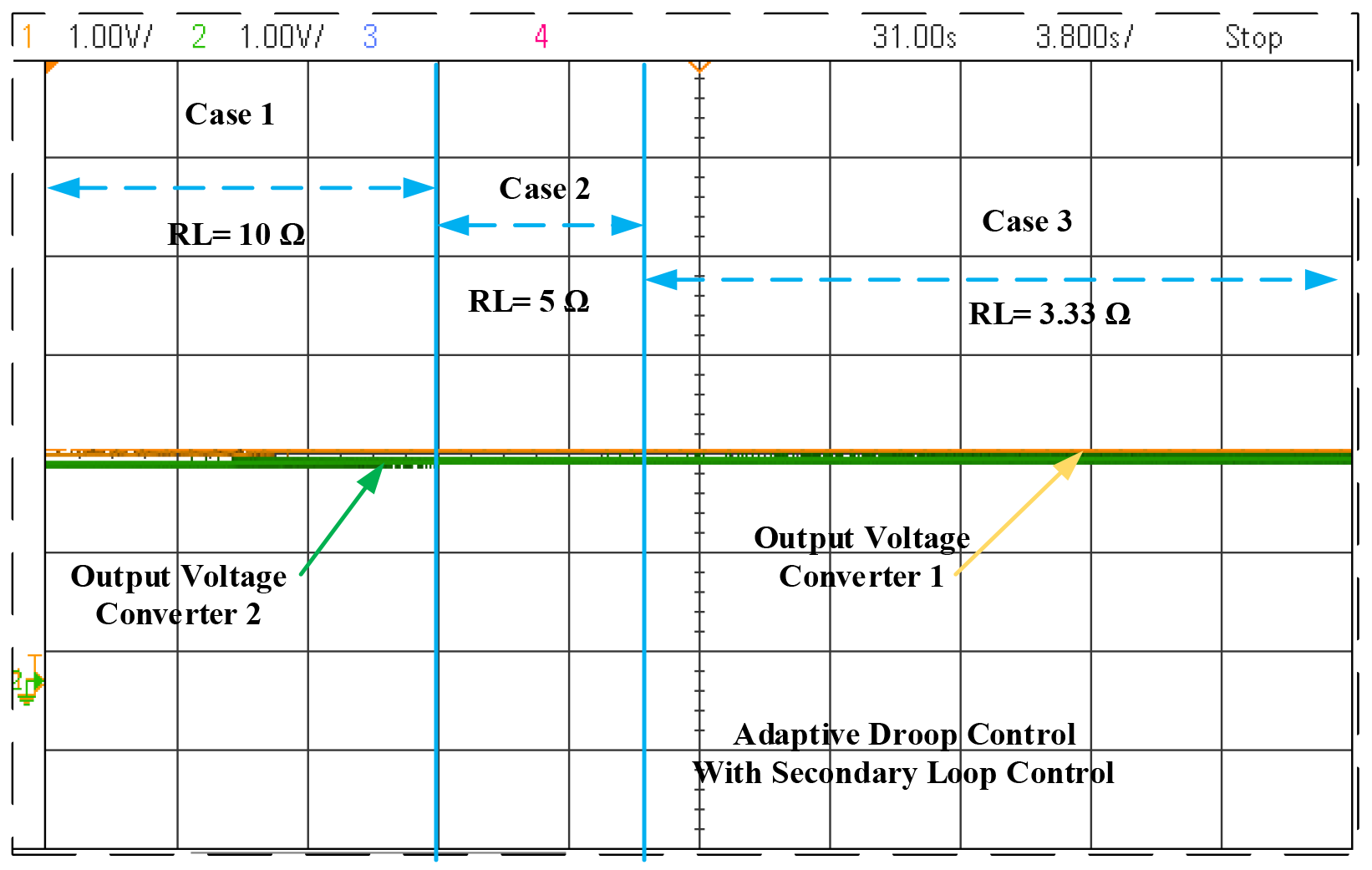
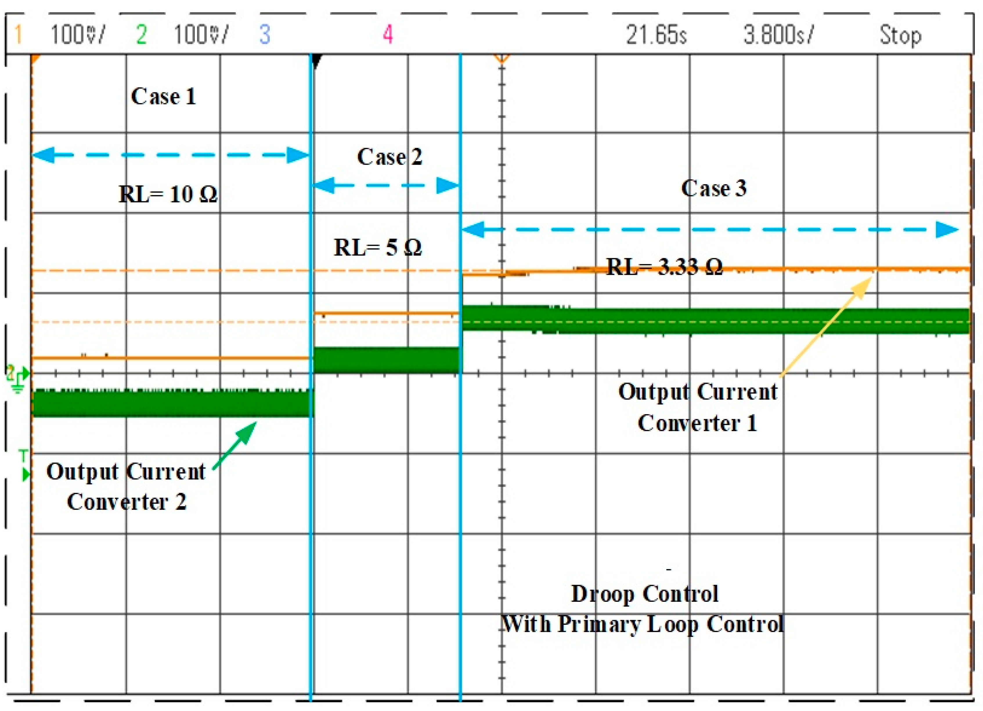
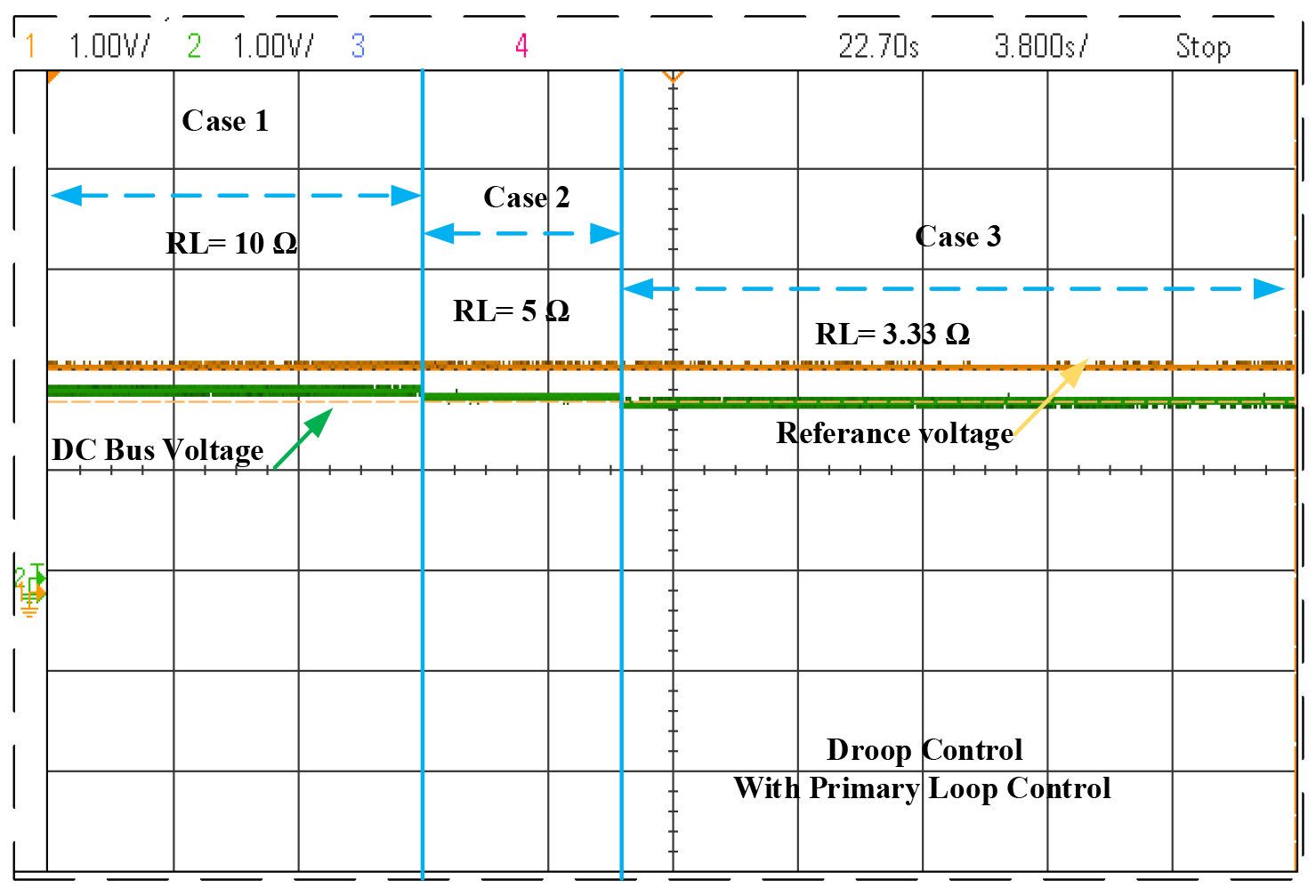
Comparison of Two Strategies

Table 2, Table 3 and Table 4 give the simulation results for the load sharing error and circulation current for various cable resistance conditions, varying loads and cable resistances, and varying source voltages and loads. Figure 18 and Figure 19 Comparison between bus voltage, and Figure 20 bus current at (A) Droop gain with primary control, (B) Adaptive droop gain with secondary control during load changes of 10 to 5 and 3.33 and input voltage changes. Table 5 shows case studies of parallel DC-DC converter phenomenon.

4. Discussion

The difference in current sharing between source converters, in this case, the value of current sharing varies. When loading is low, medium, or heavy, the highest current sharing error for the droop control with primary control is 9.11%, 9.25%, and 9.29%, compared to 5.13%, 2.04%, and 0.72% for the suggested adaptive droop with secondary control. Under different loading conditions, the results show that the current sharing error is relatively low. In addition, the proposed technique allows for the voltage deviation for the droop control with primary control is 2.65%, 5.08%, and 7.4%, compared to 0.48%, 0.94%, and 1.29% for the suggested adaptive droop with secondary control. to remain within acceptable bounds even under a variety of operating scenarios with low, medium, and high loading circumstances.

5. Conclusions

The classical droop control has been improved in this study utilize by selecting the droop coefficients on-line. Reduce bus voltage variation and improve current sharing precision in droop-controlled DC microgrids. The on-line adaptation approach is designed to change the droop control resistance in response to voltage and current variations. The proposed control is simple and does not require any additional measurements or inter-source converter communication. The simulation test procedures were performed, and this work assesses the performance using MATLAB/SIMULINK and Real-Time Simulation OPAL-RT OP4510, and the proposed control approach was evaluated, appraised, and compared to droop control under various operating conditions. There are drawbacks to using fixed droop settings in DC microgrids. This scenario illustrates an adaptive control technique for removing bus voltage variation and circulating current across converters with proper load current sharing. The results demonstrate how the proposed approach improves load current sharing between the converters and reduces output voltage variance. Future work will include the development of a control system with optimization for buck-boost for different applications, a DC microgrid with different types of sources, and energy storage to assess the impact of other sources.

Author Contributions

Conceptualization, K.S., A.A. and A.S.A.; methodology, M.A.M. (Mohamed A. Mesbah), M.A.M. (Mahmoud A. Mossa) and Z.M.S.E.; software, M.A. and M.A.M. (Mohamed A. Mesbah); validation, K.S., M.A.M. (Mohamed A. Mesbah) and A.A.; formal analysis, A.S.A. and K.S.; investigation, M.A.M. (Mohamed A. Mesbah), M.A.M. (Mahmoud A. Mossa) and K.S.; resources, M.A.M. (Mohamed A. Mesbah); data curation, A.A. and M.A.M. (Mahmoud A. Mossa); writing—original draft preparation, M.A.M. (Mohamed A. Mesbah), K.S., A.A. and M.A.; writing—review and editing, M.A.M. (Mohamed A. Mesbah), K.S., A.A. and M.A.; visualization, M.A.M. (Mohamed A. Mesbah) and Z.M.S.E.; supervision, A.A. and M.A.M. (Mahmoud A. Mossa); project administration, A.A. and M.A.M. (Mahmoud A. Mossa); funding acquisition, Z.M.S.E. and A.S.A. All authors have read and agreed to the published version of the manuscript.

Funding

The authors extend their appreciation to the Deanship of Scientific Research at King Khalid University for funding this work through the General Research Project under Grant number (RGP.1/342/44).

Data Availability Statement

The raw data supporting the conclusions of this article will be made available by the authors on request.

Conflicts of Interest

The authors declare no conflicts of interest.

References

  1. Mumtaz, F.; Yahaya, N.Z.; Meraj, S.T.; Singh, B.; Kannan, R.; Ibrahim, O. Review on non-isolated DC-DC converters and their control techniques for renewable energy applications. Ain Shams Eng. J. 2021, 12, 3747–3763. [Google Scholar] [CrossRef]
  2. Alam, S.; Al-Ismail, F.S.; Rahman, S.M.; Shafiullah; Hossain, A. Planning and protection of DC microgrid: A critical review on recent developments. Eng. Sci. Technol. Int. J. 2023, 41, 101404. [Google Scholar] [CrossRef]
  3. Srinivasan, M.; Kwasinski, A. Control analysis of parallel DC-DC converters in a DC microgrid with constant power loads. Int. J. Electr. Power Energy Syst. 2020, 122, 106207. [Google Scholar] [CrossRef]
  4. Qin, Y.; Yang, Y.; Li, S.; Huang, Y.; Tan, S.-C.; Hui, S.Y. A High-Efficiency DC/DC Converter for High-Voltage-Gain, High-Current Applications. IEEE J. Emerg. Sel. Top. Power Electron. 2019, 8, 2812–2823. [Google Scholar] [CrossRef]
  5. Baranwal, M.; Askarian, A.; Salapaka, S.; Salapaka, M. A Distributed Architecture for Robust and Optimal Control of DC Microgrids. IEEE Trans. Ind. Electron. 2018, 66, 3082–3092. [Google Scholar] [CrossRef]
  6. Bharath, K.R.; Krishnan, M.M.; Kanakasabapathy, P. A Review on DC Microgrid Control Techniques, Applications and Trends. Int. J. Renew. Energy Res. 2019, 9, 1328–1338. [Google Scholar] [CrossRef]
  7. Dahale, S.; Das, A.; Pindoriya, N.M.; Rajendran, S. An overview of DC-DC converter topologies and controls in DC microgrid. In Proceedings of the 2017 7th International Conference on Power Systems (ICPS), Pune, India, 21–23 December 2017; pp. 410–415. [Google Scholar]
  8. Silva, W.W.A.G.; Oliveira, T.R.; Donoso-Garcia, P.F. An Improved Voltage-Shifting Strategy to Attain Concomitant Accurate Power Sharing and Voltage Restoration in Droop-Controlled DC Microgrids. IEEE Trans. Power Electron. 2020, 36, 2396–2406. [Google Scholar] [CrossRef]
  9. Ghanbari, N.; Bhattacharya, S. Adaptive Droop Control Method for Suppressing Circulating Currents in DC Microgrids. IEEE Open Access J. Power Energy 2020, 7, 100–110. [Google Scholar] [CrossRef]
  10. He, W.; Namazi, M.M.; Koofigar, H.R.; Amirian, M.A.; Guerrero, J.M. Voltage regulation of buck converter with constant power load: An adaptive power shaping control. Control. Eng. Pract. 2021, 115, 104891. [Google Scholar] [CrossRef]
  11. Yuan, M.; Fu, Y.; Mi, Y.; Li, Z.; Wang, C. Hierarchical control of DC microgrid with dynamical load power sharing. Appl. Energy 2019, 239, 1–11. [Google Scholar] [CrossRef]
  12. Ahmed, S.; Kashif, S.A.R.; Ain, N.U.; Rasool, A.; Shahid, M.S.; Padmanaban, S.; Ozsoy, E.; Saqib, M.A. Mitigation of Complex Non-Linear Dynamic Effects in Multiple Output Cascaded DC-DC Converters. IEEE Access 2021, 9, 54602–54612. [Google Scholar] [CrossRef]
  13. Mohammadi, J.; Ajaei, F.B. Improved Mode-Adaptive Droop Control Strategy for the DC Microgrid. IEEE Access 2019, 7, 86421–86435. [Google Scholar] [CrossRef]
  14. Muchande, S.; Thale, S. Design and Implementation of Autonomous Low Voltage DC Microgrid with Hierarchical Control. In Proceedings of the 2020 IEEE First International Conference on Smart Technologies for Power, Energy and Control (STPEC), Nagpur, India, 25–26 September 2020; pp. 1–6. [Google Scholar]
  15. Hamed, S.B.; Ben Hamed, M.; Sbita, L. Robust Voltage Control of a Buck DC-DC Converter: A Sliding Mode Approach. Energies 2022, 15, 6128. [Google Scholar] [CrossRef]
  16. Reddy, P.K.G.; Dasarathan, S.; Krishnasamy, V. Investigation of Adaptive Droop Control Applied to Low-Voltage DC Microgrid. Energies 2021, 14, 5356. [Google Scholar] [CrossRef]
  17. Cheng, Z.; Li, Z.; Li, S.; Gao, J.; Si, J.; Das, H.S.; Dong, W. A novel cascaded control to improve stability and inertia of parallel buck-boost converters in DC microgrid. Int. J. Electr. Power Energy Syst. 2020, 119, 105950. [Google Scholar] [CrossRef]
  18. Liu, Y.; Zhuang, X.; Zhang, Q.; Arslan, M.; Guo, H. A novel droop control method based on virtual frequency in DC microgrid. Int. J. Electr. Power Energy Syst. 2020, 119, 105946. [Google Scholar] [CrossRef]
  19. Bhosale, R.; Gupta, R.; Agarwal, V. A Novel Control Strategy to Achieve SOC Balancing for Batteries in a DC Microgrid Without Droop Control. IEEE Trans. Ind. Appl. 2021, 57, 4196–4206. [Google Scholar] [CrossRef]
  20. Jiang, Y.; Yang, Y.; Tan, S.-C.; Hui, S.-Y.R. Distribution Power Loss Mitigation of Parallel-Connected Distributed Energy Resources in Low-Voltage DC Microgrids Using a Lagrange Multiplier-Based Adaptive Droop Control. IEEE Trans. Power Electron. 2021, 36, 9105–9118. [Google Scholar] [CrossRef]
  21. Liu, H.; Guo, W.; Cheng, D.; Wang, Y.; Wang, M. Stability and Bifurcation Analysis of DC Microgrid with Multiple Droop Control Sources and Loads. IEEE Trans. Power Electron. 2020, 36, 2361–2372. [Google Scholar] [CrossRef]
  22. Peyghami, S.; Davari, P.; Mokhtari, H.; Blaabjerg, F. Decentralized Droop Control in DC Microgrids Based on a Frequency Injection Approach. IEEE Trans. Smart Grid 2019, 10, 6782–6791. [Google Scholar] [CrossRef]
  23. Ingle, A.; Shyam, A.B.; Sahoo, S.R.; Anand, S. Quality-Index Based Distributed Secondary Controller for a Low-Voltage DC Microgrid. IEEE Trans. Ind. Electron. 2018, 65, 7004–7014. [Google Scholar] [CrossRef]
  24. Gao, F.; Kang, R.; Cao, J.; Yang, T. Primary and secondary control in DC microgrids: A review. J. Mod. Power Syst. Clean Energy 2018, 7, 227–242. [Google Scholar] [CrossRef]
  25. Mossa, M.A.; Gam, O.; Bianchi, N.; Quynh, N.V. Enhanced Control and Power Management for a Renewable Energy-Based Water Pumping System. IEEE Access 2022, 10, 36028–36056. [Google Scholar] [CrossRef]
  26. Kreiss, J.; Bodson, M.; Delpoux, R.; Gauthier, J.-Y.; Trégouët, J.-F.; Lin-Shi, X. Optimal control allocation for the parallel interconnection of buck converters. Control. Eng. Pract. 2021, 109, 104727. [Google Scholar] [CrossRef]
  27. Roslan, M.; Hannan, M.; Ker, P.J.; Uddin, M. Microgrid control methods toward achieving sustainable energy management. Appl. Energy 2019, 240, 583–607. [Google Scholar] [CrossRef]
  28. Zhang, Y.; Qu, X.; Tang, M.; Yao, R.; Chen, W. Design of Nonlinear Droop Control in DC Microgrid for Desired Voltage Regulation and Current Sharing Accuracy. IEEE J. Emerg. Sel. Top. Circuits Syst. 2021, 11, 168–175. [Google Scholar] [CrossRef]
  29. Al-Ismail, F.S. DC Microgrid Planning, Operation, and Control: A Comprehensive Review. IEEE Access 2021, 9, 36154–36172. [Google Scholar] [CrossRef]
  30. Kreishan, M.Z.; Zobaa, A.F. Optimal Allocation and Operation of Droop-Controlled Islanded Microgrids: A Review. Energies 2021, 14, 4653. [Google Scholar] [CrossRef]
  31. Xie, W.; Han, M.; Cao, W.; Guerrero, J.M.; Vasquez, J.C. System-Level Large-Signal Stability Analysis of Droop-Controlled DC Microgrids. IEEE Trans. Power Electron. 2020, 36, 4224–4236. [Google Scholar] [CrossRef]
  32. Sayed, K.; Abdel-Khalek, S.; Zakaly, H.M.H.; Aref, M. Energy Management and Control in Multiple Storage Energy Units (Battery–Supercapacitor) of Fuel Cell Electric Vehicles. Materials 2022, 15, 8932. [Google Scholar] [CrossRef]
  33. Poursafar, N.; Taghizadeh, S.; Hossain, M.; Blaabjerg, F. An enhanced control strategy for an ultra-fast EV charging station in a DC microgrid. Int. J. Electr. Power Energy Syst. 2023, 146, 108727. [Google Scholar] [CrossRef]
  34. Seth, A.K.; Singh, M. Unified adaptive neuro-fuzzy inference system control for OFF board electric vehicle charger. Int. J. Electr. Power Energy Syst. 2021, 130, 106896. [Google Scholar] [CrossRef]
  35. Macharia, V.M.; Garg, V.K.; Kumar, D. A review of electric vehicle technology: Architectures, battery technology and its management system, relevant standards, application of artificial intelligence, cyber security, and interoperability challenges. IET Electr. Syst. Transp. 2023, 13, e12083. [Google Scholar] [CrossRef]
  36. Ferahtia, S.; Djerioui, A.; Rezk, H.; Chouder, A.; Houari, A.; Machmoum, M. Adaptive Droop based Control Strategy for DC Microgrid Including Multiple Batteries Energy Storage Systems. J. Energy Storage 2022, 48, 103983. [Google Scholar] [CrossRef]
Figure 1. Power sources in the DC-MG configuration can be interconnected.
Energies 17 00284 g001
Figure 2. DC-DC buck converter configuration scheme.
Energies 17 00284 g002
Figure 3. (A) Equivalent DC-DC circuit. (B) Equivalent DC-DC circuit with R droop.
Energies 17 00284 g003
Figure 4. Traditional droop control for distributed resource DC microgrids.
Energies 17 00284 g004
Figure 5. The connection between constant virtual droop resistances and current sharing.
Energies 17 00284 g005
Figure 6. Parallel buck converter control schematic with adaptive droop control.
Energies 17 00284 g006
Figure 7. (a) Simulation model. (b) Real-Time OPAL-RT OP4510.
Energies 17 00284 g007
Figure 8. Flowchart for droop control technique submitted.
Energies 17 00284 g008
Figure 9. The bus voltage between the two DG units has been restored.
Energies 17 00284 g009
Figure 10. Change the input voltage of two buck converters.
Energies 17 00284 g010
Figure 11. Comparison between Droop Voltage at (a) Droop Voltage with primary control, (b) Droop Voltage with secondary control during load changes of 10 to 5 and 3.33 and input voltage changes.
Energies 17 00284 g011
Figure 12. The transient response for Droop gain with primary control MATLAB/SIMULINK with a step load change from 10 Ω to 5 Ω and 3.33 Ω and step change in the input voltage.
Energies 17 00284 g012
Figure 13. The transient response Adaptive droop gain with secondary control MATLAB/SIMULINK with a step load change from 10 Ω to 5 Ω and 3.33 Ω and step change in the input voltage.
Energies 17 00284 g013
Figure 14. Output voltage of droop gain with primary control, during load changes of 10 to 5 and 3.33 and input voltage changes.
Energies 17 00284 g014
Figure 15. The output voltage of adaptive droop gain with secondary control during load changes of 10 to 5 and 3.33 and input voltage changes.
Energies 17 00284 g015
Figure 16. The output current of two converters at droop gain with primary control during load changes of 10 to 5 and 3.33 and input voltage changes.
Energies 17 00284 g016
Figure 17. The output current of two converters at Adaptive droop gain with secondary control during load changes of 10 to 5 and 3.33 and input voltage changes.
Energies 17 00284 g017
Figure 18. Bus voltage at droop gain with primary control, during load changes of 10 to 5 and 3.33 and input voltage changes.
Energies 17 00284 g018
Figure 19. Bus voltage at adaptive droop gain with secondary control during load changes of 10 to 5 and 3.33 and input voltage changes.
Energies 17 00284 g019
Figure 20. Comparison between current DC bus at (a) Droop gain with primary control, (b) Adaptive droop gain with secondary control during load changes of 10 to 5 and 3.33 and input voltage changes.
Energies 17 00284 g020
Table 1. Parameters of DC-DC buck converters.
ParametersSymbolValues
Ideal voltage DC busVDC48 V
Current rating for sourceI rated20 A
Resistance of line-1R10.1 Ω
Resistance of line-2R20.2 Ω
Inductance of cable line-1L10.2 mH
Inductance of cable line-2L20.4 mH
Resistance of capacitor 1rc10.03 Ω
Resistance of capacitor 2rc20.03 Ω
Table 2. Comparing between two strategies with a step change in load resistance 10 Ω.
MethodV Bus (V)I Bus (I1, I2) (A) Δ  I Circulate % Δ  V
Bus %
Droop gain with primary control 46.734.674
(2.55, 2.124)
9.112.65
Adaptive droop gain with secondary control 47.774.777
(2.511, 2.266)
5.130.48
Table 3. Comparing between two strategies with a step change in load resistance 5 Ω.
MethodV Bus (V)I Bus (I1, I2) (A) Δ  I Circulate % Δ  V
Bus %
Droop gain with primary control 45.569.108
(4.975, 4.132)
9.255.08
Adaptive droop gain with secondary control 47.559.509
(4.851, 4.657)
2.040.94
Table 4. Comparing between two strategies with a step change in load resistance 3.33 Ω.
MethodV Bus (V)I Bus (I1, I2) (A) Δ  I Circulate % Δ  V
Bus %
Droop gain with primary control 44.4513.33
(7.282, 6.044)
9.297.4
Adaptive droop gain with secondary control 47.3814.21
(7.157, 7.055)
0.721.29
Table 5. Case studies of parallel DC-DC converter phenomenon.
CaseInput
Voltages
Vi1–Vi2
Cable
Resistances
R1–R2
Output Voltages
V1–V2
Output Currents
I1–I2
1EqualEqualEqualEqual
2EqualUnequalEqualUnequal
3UnequalEqualUnequalUnequal
4UnequalUnequalUnequalUnequal
Disclaimer/Publisher’s Note: The statements, opinions and data contained in all publications are solely those of the individual author(s) and contributor(s) and not of MDPI and/or the editor(s). MDPI and/or the editor(s) disclaim responsibility for any injury to people or property resulting from any ideas, methods, instructions or products referred to in the content.

