1. Introduction
The deployment of renewable energy resources (RESs) has gained significant attention in recent years due to their potential in mitigating climate change. However, the increasing penetration of RESs poses substantial challenges to the secure and economic operation of the power grid [
1,
2,
3]. For distributed photovoltaic (PV) systems connected to the power grid, if excessive PV power cannot be consumed locally, it will flow back into the grid, resulting in issues such as reverse power flow and overvoltage violations [
4]. To address these problems, flexible user-side resources (FURs) have emerged as a promising solution. FURs refer to electricity-consuming devices (e.g., energy storage systems, electric vehicles, and adjustable loads) that can rapidly adjust their power demands in response to control signals from the grid operator or changes in system status. By actively participating in grid operations, FURs can provide system flexibility and support the large-scale integration of RESs.
Many efforts have been made in describing the regulation of FURs. Some early proposed methods are based on traditional deterministic models with minimum capacity constraints to enable scheduling results that cope with uncertainties within a certain cost [
5]. In [
6], a multi-timescale model for FURs in the day-ahead dispatch is proposed, achieving optimized configuration with intervals of 10, 15, and 30 min. Both [
5] and [
6] are based on deterministic models, which impose high requirements on the precise assessment of flexibility demands. To deal with the inevitable uncertainties, [
7] demonstrates the superiority of the stochastic optimization model over the deterministic unit commitment model considering FUR provisions. The stochastic optimization method transforms a stochastic optimization problem into an optimization scheduling problem under multiple probabilistic scenarios by constructing a chance-constrained model of system-related uncertain variables and limiting the probability of these chance constraints [
8,
9]. Unlike the stochastic optimization method, robust optimization does not rely on the precise probability distribution of system-uncertain variables. Instead, it uses uncertainty set parameters based on statistical intervals to solve for the economic dispatch due to its ability to provide an acceptable performance for all implementations of uncertain inputs [
10,
11]. In [
12], a flexible regulation cost is introduced into the model to balance the robustness and economic efficiency of the robust optimization results. Furthermore, methods based on new theories such as reinforcement learning have been applied to handle the optimization problems of FURs. The authors of [
13] explore and utilize the uncertainty and fluctuation patterns of wind power, PV power, and multi-energy loads through deep reinforcement learning methods to achieve system optimization scheduling and decision-making under complex scenarios. Other control strategies for microgrids, energy storage systems, and electric vehicles can be found in [
14,
15,
16], respectively. Additionally, the demand response of integrated FURs has been comprehensively considered in [
17,
18,
19] for the coordination of integrated energy systems.
Although considerable progress has been made in the modeling of FURs, most coordination strategies are based on centralized solutions to the optimal power flow problem. A second-order cone programming (SOCP) approach is employed in [
20,
21] to optimize the active and reactive power output of FURs in distribution networks. These centralized methods require the control center to collect operational parameters of all distributed RESs in real time, which is challenging and infringes on user privacy, especially in complex distribution networks [
22]. Distributed coordination architectures have attracted significant attention as they enable regional grids to achieve high autonomy in addressing local contingencies through interactions between neighbors [
23]. Due to its excellent convergence performance, the alternating direction method of multipliers (ADMM) technique is applied in [
24,
25] to obtain global solutions through local optimization updates. However, conventional distributed algorithms require multiple iterations before applying the final converged solution to local controllers. By the time convergence is achieved, the control objectives may have significantly deviated from the initial states due to the fast fluctuations in PV power outputs in real time. Consequently, the response speed of local controllers cannot keep up with the rapid changes in system status, hindering the online application of the program.
In this paper, we propose a distributed control strategy based on the dual ascent method to optimize distribution network operations involving FURs. By decoupling the centralized optimization operation model of the distribution network, our approach aims to maintain voltage within acceptable ranges while minimizing the total operating cost, including network losses and the regulation cost of flexible resources. As illustrated in
Figure 1, unlike traditional distributed algorithms that require complete convergence before applying the results, the proposed method is proven to have asymptotic convergence and can update and output control commands at each iteration. This facilitates a prompt and effective response to variations in PV power output.
2. Centralized Model of Power Regulation
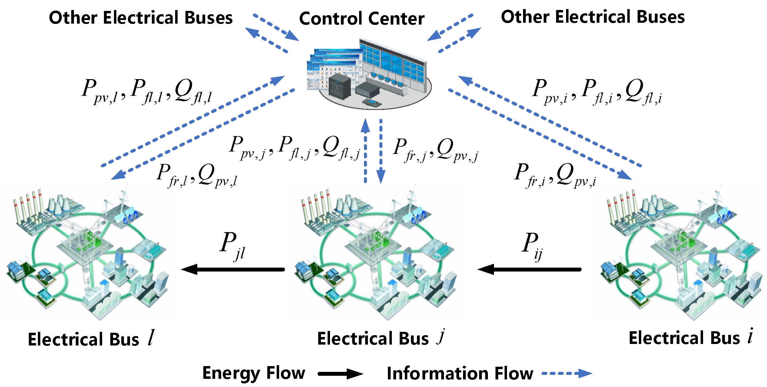
In the centralized approach, the power system operator collects electrical parameters from all buses and assigns control commands to individual agents based on optimization results, as shown in
Figure 2. Given the typical goal of optimizing power flow subject to operational constraints, the formulation of the dispatch scheme, incorporating PV systems and FURs, is summarized as follows.
2.1. Objective Function of Distribution Networks
The objective function for the entire system is to minimize the overall cost, which includes the network losses
and the compensation cost
associated with the regulation of FURs, namely
2.1.1. Network Losses
The network losses
are determined by
where
represents the set of lines;
is the resistance of line
;
and
denote the active and reactive power flow on line
and are dependent variables influenced by the optimized decision variables; and
and
represent the voltage magnitudes at bus
and the substation bus, respectively. Given that the voltage drop along the distribution network is not significant, we make a reasonable assumption that
for ease of calculation.
2.1.2. Compensation Cost
The compensation cost
is evaluated by a convex quadratic function [
26] and can be expressed as
where
represents the output of FURs; and
is a positive definite matrix, and its properties will be discussed in more detail in
Section 2.3. Clearly,
exhibits strict monotonicity, which is consistent with the trend of the compensation cost.
denotes a correlation coefficient, where a larger value of
means a higher compensation cost and leads to reduced power support of FURs, and vice versa.
2.2. Operational Constraints of Distribution Networks
The goal of distribution networks is to optimize energy efficiency and reduce network losses by adjusting the dispatch scheme for distributed energy resources and flexible loads. To achieve these objectives, it is essential to consider operational constraints, including power flow constraints, inverter control constraints, voltage violation constraints, and power regulation constraints.
2.2.1. Power Flow Constraints
Due to the non-convexity of the branch flow model, the linearized DistFlow [
27] approximation will be employed to simplify the problem. By neglecting the higher-order terms, we obtain the following equations.
where
,
and
are matrices corresponding to
,
and
, respectively;
and
represent the injected active and reactive power, respectively;
and
are diagonal matrices with their diagonal entries corresponding to the resistance
and the reactance
of line
;
and
denote the active and reactive power for the PV system; and
and
represent the load demands. The constant matrices
and
together form the adjacency matrix
, where
constitutes the first column of
. Specifically,
is expressed as
. The adjacency matrix
is mathematically defined as
where
denotes the element in the
-th row and
-th column of matrix
. It is noteworthy that
is a square matrix with full rank and, therefore, it is invertible [
28].
2.2.2. Inverter Control Constraints
To facilitate the power flow in the distribution network, the IEEE 1547 standard [
29] allows small-scale distributed PV inverters to engage in power flow optimization by adjusting their reactive power output.
where
and
represent the lower and upper reactive power limits of the inverters.
2.2.3. Voltage Violation Constraints
To ensure proper operation, it is imperative to maintain bus voltage magnitudes within the acceptable ranges as
where
and
denote the lower and upper voltage limits.
2.2.4. Power Regulation Constraints
In order to accommodate as much PV power as possible, FURs dynamically update their power output to mitigate voltage violations, responding to rapid fluctuations in PV power. These FURs typically include contracted and price-responsive resources. The modeling of different types of FURs will be addressed in future work. For the present analysis, our focus is on examining the impact of power regulation associated with FURs. Therefore, we have
where
and
are the lower and upper limits of FURs’ output, and
and
represent the lower and upper transmission power limits. To prevent excessive PV power injection into the upstream grid and to manage the significant burden caused by evening peak load demand, power system operators periodically adjust the power regulation constraints on the grid interconnection lines based on upstream grid load levels. This proactive measure ensures efficient and balanced power distribution. Therefore, in addition to the thermal limit, the
and
connected to the substation bus also represent the exchanged power limit on the grid interconnection, which will be set by the power system operator.
2.3. The Compact Form of Centralized Optimization Model
Substituting (4) and (5) into (6), the bus voltage is given by
where
and
. Equation (14) builds a linear relationship between bus voltage magnitudes and nodal power injections. Since it has been proven in [
30] that
and
are positive definite, the network losses in (2) can be further represented in matrix form as
Substituting (7) and (8) into (15), the compact form of centralized optimization mode is finally obtained as follows.
It is worth noting that the decision variables in optimization (16) are the active power output of FURs and the reactive power output of PV inverters.
3. Distributed Model of Power Regulation
In this section, a distributed architecture is applied to the distribution network with the dual ascent method. As shown in
Figure 3, instead of collecting the operational state of the entire network, distributed algorithms can achieve global optimality through interactions between neighbors, thereby preserving user privacy. Additionally, the proposed method in this paper has a desirable property that facilitates the involvement of FURs in real-time power regulation. Traditional distributed algorithms always require convergence before applying the optimized results to actual outputs and reading new inputs to enter a new iteration cycle. However, the proposed dual ascent method has been proven to converge asymptotically to the optimal value, which means that each iteration result is better than the previous ones (refer to [
26] for detailed proofs). As a result, the output from each iteration step can be applied even before the algorithm converges, enabling the controller to update the signal in real time. This leads to better tracking and response performance when applied to power regulation.
3.1. Dual Ascent Method
The dual ascent method solves the optimization problem by iteratively updating the primal and dual variables, alternately using the gradients. The typical iterative form of the dual ascent method is given as
where
and
represent the primal and dual variables, respectively;
denotes the step size in step
;
is the Lagrangian function; and
is the gradient of the dual function
. Since
represents the feasible set of
, then
denotes the mapping projected onto set
.
3.2. Update Rules for Dual Ascent Method
In this section, the update rules of the primal and dual variables are first presented. Subsequently, for better comprehension, the specific implementation steps of the proposed method are provided.
3.2.1. Update Rules for Primal Variables
Considering that the decision variables in optimization model (16) are
and
, the Lagrangian function
can be reformulated by halving the objective function value and eliminating the constant terms as
where
and
;
,
,
,
,
,
,
,
are dual variables or Lagrange multipliers corresponding to (10)–(13), respectively. Obviously,
and
are symmetric matrices, i.e.,
and
. Therefore, according to the derivation of the Lagrange function (19), the update rules for primal variables
and
in
-th step are achieved as
3.2.2. Update Rules for Dual Variables
The dual ascent method optimizes the dual variables by utilizing gradient ascent during each iteration. The update rules for dual variables
,
,
,
,
,
,
, and
in the
-th step are obtained as
3.2.3. Implementation of Update Rules
The proposed method only requires us to receive dual variables from neighboring buses and update the primal variables locally, as shown in
Figure 3. It is worth noting that the primal and dual variables may not be within the defined domain due to approximation. Therefore, the usual approach is to map them back into the defined domain, where the primal variables adhere to Constraints (10)–(13), while the dual variables need to satisfy non-negativity, i.e., operator
in (22)–(29). The pseudo code of dual ascent method is shown in Algorithm 1.
| Algorithm 1: Dual Ascent Method |
For a given -bus distribution network,
1: Initialize primal variables , and dual variables , , , , , , , , set step .
2: Repeat
3: For bus , do
4: Input the local voltage magnitude .
5: Update the dual variables according to (22)–(29);
6: Send , , , , , , , to parents buses and , , , to child buses.
7: Receive , , , from parent buses and , , , , , , , from child buses.
8: Update the primal variables according to (20)–(21) and map them into the feasible range.
9: Output the dispatch instruction and .
10: .
11: Until stopping criteria are met. |
4. Case Studies
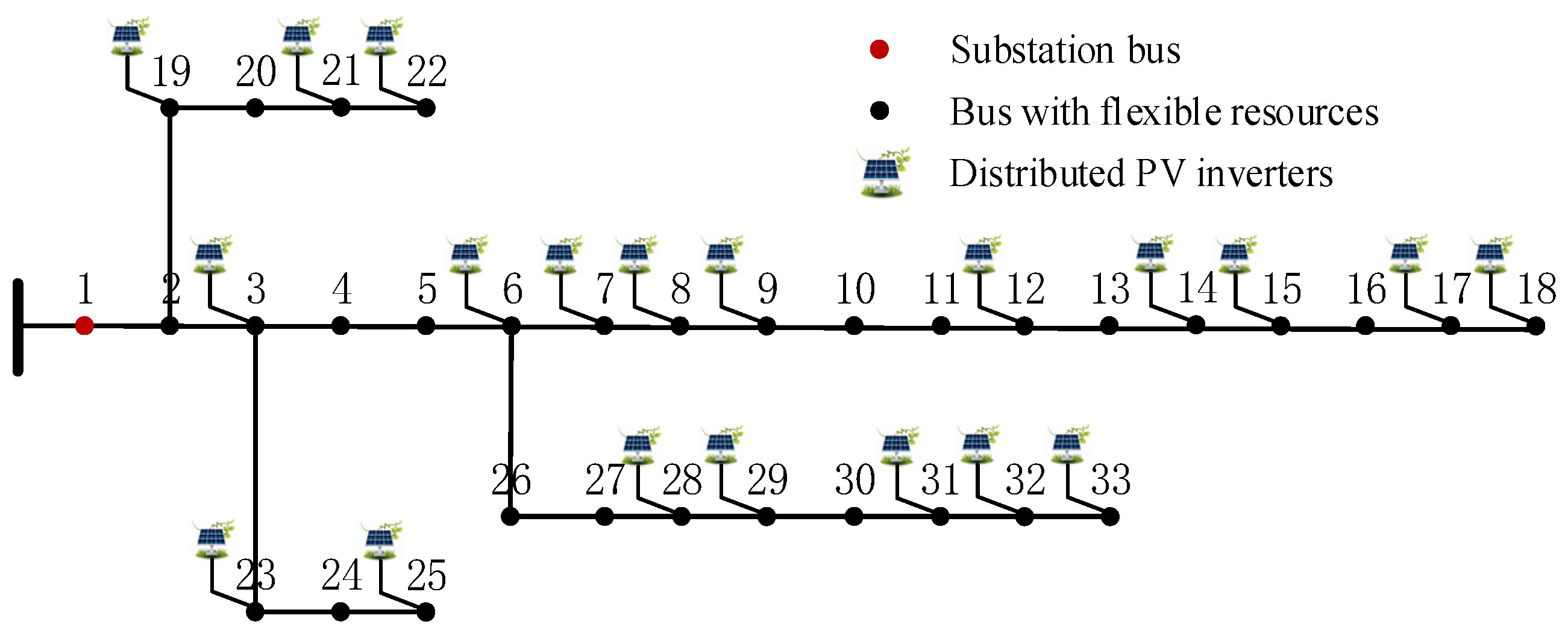
A modified IEEE 33-bus distribution system is simulated for case studies in this paper, as shown in
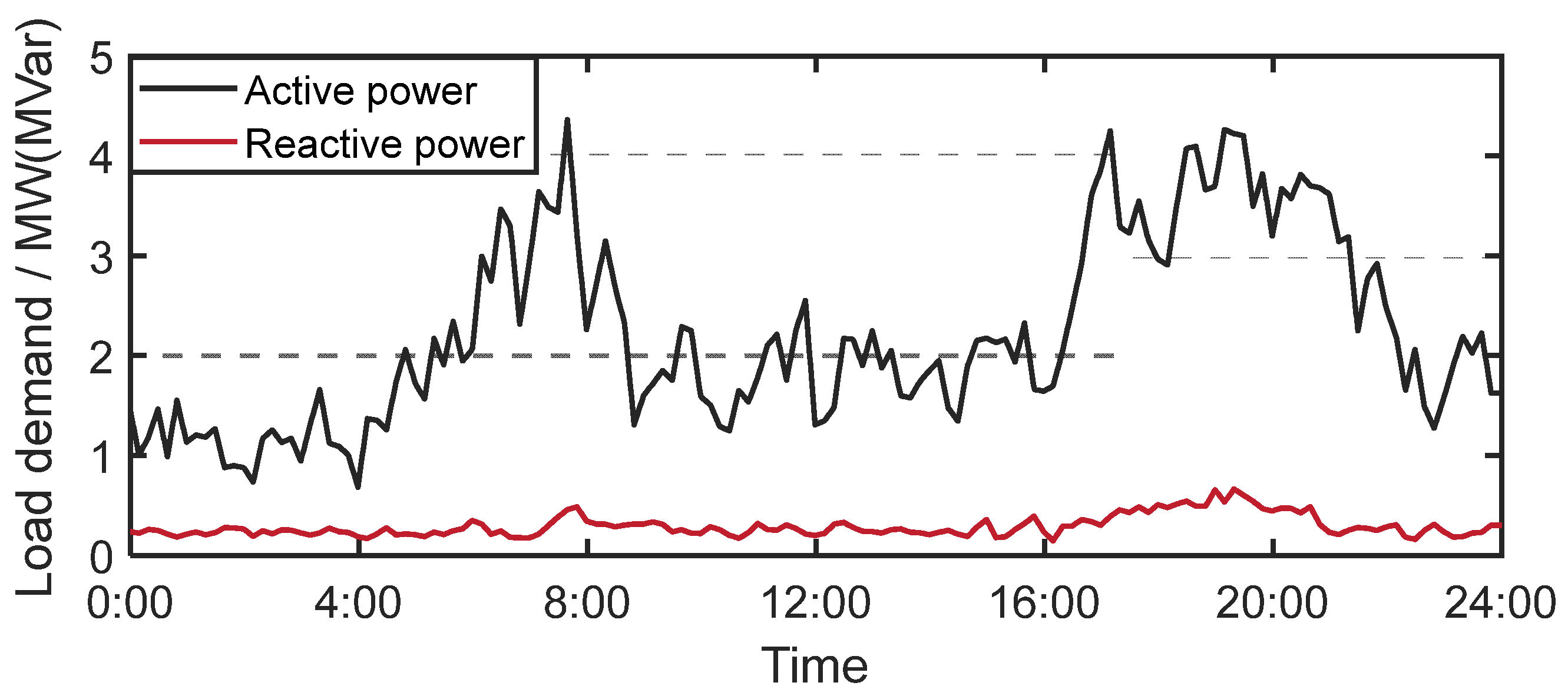
Figure 4. The lower and upper limits of voltage magnitude are set to 0.95 p.u. and 1.05 p.u., respectively. According to the IEEE 1547 standard, distributed PV inverters are allowed to participate in voltage control by providing Var compensation at a power factor not less than 0.9 (i.e., the maximum reactive power is 0.4385 of the corresponding active power). In addition, except for the substation bus, all other buses have flexible loads that can perform power regulation within 30% of the peak load power. The profiles of PV power, active, and reactive loads in the distribution system within a day are given in
Figure 5 and
Figure 6. To expedite the convergence,
,
,
,
,
,
,
,
are set to be
. The primal variables
,
and dual variables
,
,
,
,
,
,
,
are all initialized to zero for the convenience of comparison. The terminal bus 18, which is prone to overvoltage, is selected to analyze the effectiveness of different control strategies. All numerical tests are conducted on a 2.6 GHz Intel Core i5 personal computer with 16 GB of memory. The algorithms are implemented in MATLAB R2023a, and the models are solved using the commercial solver CPLEX 12.7 via the YALMIP toolbox. All solvers are utilized with their default settings to ensure consistency and reliability in the results.
4.1. Convergence Performance of Proposed Algorithm
In this section, overvoltage events are simulated to analyze the convergence performance of the proposed algorithm under different step sizes. The parameter is crucial in the optimization process during the iterative steps of the distributed algorithm, as it directly impacts the effectiveness of mitigating overvoltage violations, as indicated in (26). Consequently, we focus on the values of the parameter while keeping the values of other step sizes unchanged to ensure overall stability and optimal performance.
Figure 7 and
Figure 8 depict the convergence performance of objective values and voltage magnitudes under different values of
. After a sufficient number of iterations, all three parameter choices in the distributed algorithm converge to the same optimal solution as the centralized problem (i.e., the objective value and voltage magnitude are 19 kW and 1.05 p.u., respectively). The step sizes
and
are relatively small, resulting in slower convergence speeds. In contrast, the algorithm with step size
exhibits better convergence performance in terms of the optimization objective function, almost eliminating voltage violations after a single iteration. By comparing the curves, it can be concluded that increasing the step size
effectively accelerates the convergence speed of the algorithm. However, a larger step size is not always preferable as it may lead to oscillations or even hinder convergence. Therefore, selecting an appropriate step size is crucial for optimizing the online application performance of the distributed algorithm.
4.2. Power Regulation Performance of FURs
To validate the long-term power regulation performance of the proposed algorithm, four representative cases are selected to demonstrate the superiority of the proposed method in optimizing the objective function and mitigating overvoltage. Considering that the proposed distributed algorithm only involves simple algebraic operations, and the majority of the time is consumed by information exchange between neighbors, it is reasonable to assume that each iteration takes approximately one second. The selected cases are as follows:
- (1)
Case 1 (only Var control): In the absence of FURs, only PV inverters participate in distributed voltage control by providing reactive power.
- (2)
Case 2 (traditional distributed algorithm): FURs and PV inverters modulate active and reactive power, respectively, to participate in distributed voltage control. This case utilizes the traditional dual ascent method, which requires convergence before applying the results to local controllers.
- (3)
Case 3 (classical ADMM algorithm): FURs and PV inverters modulate active and reactive power, respectively, to participate in distributed voltage control. This case utilizes the ADMM algorithm, which also requires convergence before applying the results to local controllers.
- (4)
Case 4 (proposed method): FURs and PV inverters modulate active and reactive power, respectively, to participate in distributed voltage control. This case employs the proposed distributed algorithm, which allows the results to be applied to local controllers in real time upon the completion of each iteration.
The parameter settings in all cases are consistent with those described in
Section 4. The only differences are in the selection of decision variables and the logic of algorithm iteration for optimization.
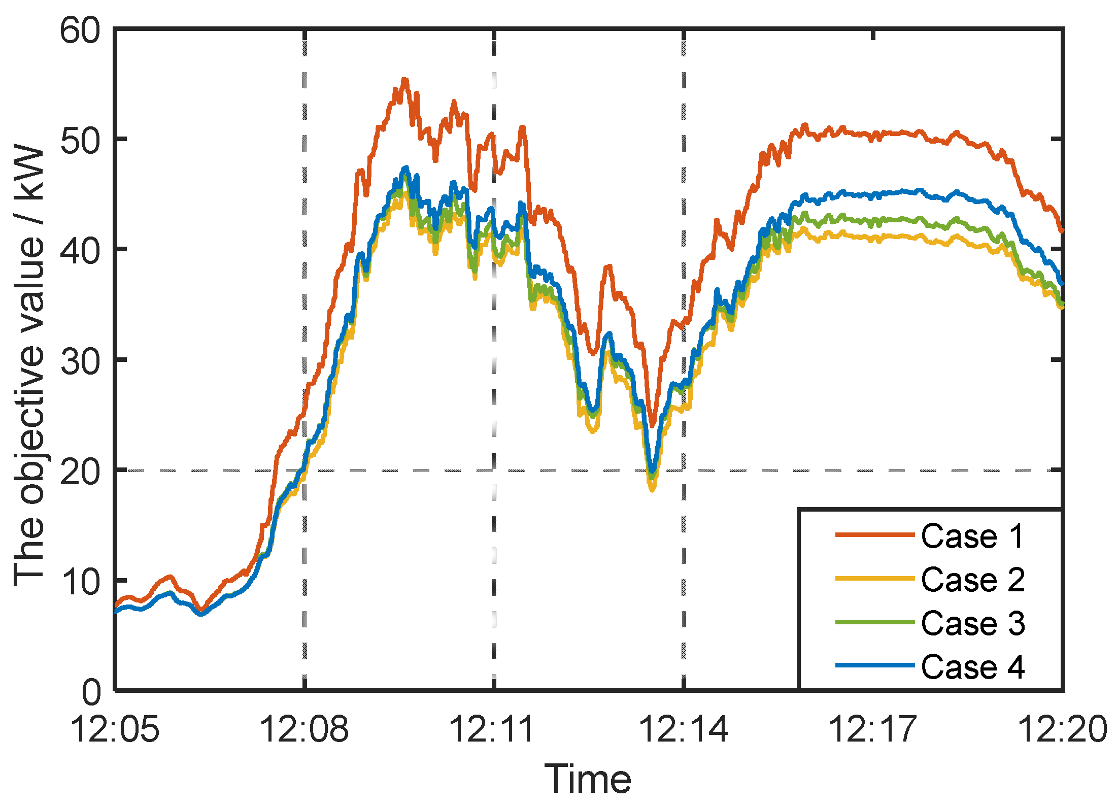
Figure 9 and
Figure 10 show the objective values and voltage magnitudes under different control strategies over a 15-minute period. Since FURs are not involved in power regulation, Case 1 requires PV inverters to absorb a significant amount of reactive power to suppress voltage rise. However, due to the relatively high ratio of R/X in the distribution network, the response of reactive power is less sensitive compared to that of active power. Additionally, the limited capacity of inverters hinders the sufficient mitigation of overvoltage violations. Consequently, Case 1 exhibits the poorest performance regarding objective values due to increased network losses. The voltage magnitudes in Case 1 frequently exceeded the upper voltage limit, leading to severe overvoltage violations.
Although Case 2 reduces operational costs by incorporating the power regulation of FURs, it employs the traditional dual ascent method, which can only apply the results to local controllers after achieving convergence. This limitation prevents it from rapidly responding to PV power fluctuations and promptly accommodating excessive PV power, resulting in voltage violations at certain instances.
Case 3, which employs the ADMM algorithm, demonstrates slightly improved convergence performances compared to the traditional dual ascent method. However, similar to the traditional dual ascent method, it requires full convergence before applying the results to local controllers.
The proposed method (i.e., Case 4) exhibits robust tracking and responsive performance. This method outputs control commands in real time at each iteration step, enabling optimized power allocation for FURs and PV inverters while maintaining voltage within an allowable range. Consequently, it effectively mitigates overvoltage violations in distribution networks with high PV penetration.
5. Conclusions
Existing distributed methods often require the algorithm to converge before issuing control instructions, which deteriorates their ability to efficiently track rapid fluctuations in PV power outputs. To improve the convergence performance of the distributed algorithm, this paper proposes an online power regulation method for flexible user-side resources based on the dual ascent method. By deconstructing the centralized problem into a primal–dual framework, the implementation method for the real-time control of flexible user-side resources is outlined.
Case studies demonstrate that the proposed model achieves a satisfactory objective value through information exchange between neighboring agents while ensuring a voltage control performance. Moreover, the appropriate values of parameters are crucial for ensuring the convergence performance of the distributed algorithm. Our future work will prioritize the modeling of different flexible user-side resources in a classified manner and integrating power coordination among heterogeneous flexible user-side resources.


