Abstract
During the fault period, a phase angle jump may occur at the stator or the point of common coupling, which will deteriorate the low-voltage ride-through (LVRT) characteristics of a doubly fed induction generator (DFIG). The existing LVRT studies focus on the impact of a voltage drop on DFIGs but often ignore that of a phase angle jump. The time-domain simulation is accurate in describing the response of a DFIG during the LVRT process, but it is time-consuming for a DFIG with the full-order model. In this paper, by using the voltage magnitude and phase angle of the stator or the point of common coupling as the inputs, and the state variables as the outputs, the transfer function of a DFIG is derived to analyze its response and find the LVRT measures against the voltage drop and, especially, the phase angle jump. Firstly, the differential-algebraic equations of the DFIG are linearized to propose their transfer function model. Secondly, considering its high-order characteristic, a model reduction method for the transfer function of the DFIG using the Schur decomposition is proposed, and the analytical expression of the output variables of the DFIG with the phase angle jump is derived by the inverse Laplace transformation to judge the necessity of the LVRT measures. Finally, the simulation results of the DFIG are provided to verify the accuracy of the transfer function model and its reduced-order form and validate the feasibility of the LVRT against the phase angle jump with the proposed models.
1. Introduction
With more new energy sources, the interaction between wind turbines and power grids continues to intensify [1,2]. There are a series of problems, usually led by the failure of the power grid, that are not conducive to the normal operation of wind turbines [3], such as decreasing stator voltage, rotor overcurrent, and increasing DC capacitor voltage. Some problems can even cause the failure of low-voltage ride-through (LVRT), which seriously threatens the safe and stable operation of the power system [4,5]. Therefore, studying the dynamic response characteristics of DFIGs during low-voltage events in points of common coupling is beneficial for wind turbine protection design and LVRT.
Ref. [6] analyzes the dynamic characteristics of the stator flux and rotor current under different fault conditions of the power grid. Ref. [7] compares the change in the rotor current before and after a crowbar is inserted and provides the optimization strategy of the crowbar resistance value. Ref. [8] analyzes the dynamic response characteristics of a DFIG based on state–space theory, which is more accurate than the traditional analytic model. Ref. [9] analyzes the formation mechanism of the fault current from the perspective of flux linkage. The above references all aimed to analyze the dynamic response characteristics of a DFIG based on voltage drop. Considering phase angle jump characteristics [10], Ref. [11] analyzes the influence of a phase angle jump on the stator flux and the rotor voltage of DFIG, finding that increasing stator flux is significantly influenced by a phase angle jump. Refs. [12,13] further study the influence of a phase angle jump on the DFIG short circuit current. Ref. [14] explores the effect of a phase angle jump on the transient characteristics of a DFIG under a weak grid. Ref. [15] analyzes the effect of a phase angle jump on the phase-locked loop tracking performance of a grid-connected inverter. Ref. [16] considers a phase angle jump to estimate turbine parameters and improves the modeling accuracy. It can be seen that some references have studied the influence of the phase angle jump on variables such as flux linkage and the current of DFIGs, but the value of the phase angle jump is a fixed value at the moment when the fault occurs, and the fluctuation phenomenon existing during the fault is not considered. Meanwhile, the analytical expression of variables, such as the short-circuit current of the DFIGs obtained in the above references, is convenient for understanding the dynamic response mechanism of DFIGs. However, the derivation process is complicated, and some simplifying assumptions are made, which affect the accuracy of the dynamic response analysis results.
In addition to the analytical expression of DFIG variables derived from the mechanism, its response characteristics can also be analyzed by a time-domain simulation [17,18]. The time-domain simulation method can accurately describe the dynamic response characteristics of the system by iteratively solving the differential differentiation equation of the system [19]. However, for high-order systems, the calculation of this method is complex and time-consuming, so it is generally used for simulation verification. The transfer function method only focuses on the output characteristics of the system under the action of the input, which is convenient for analyzing the dynamic response of the system [20,21]. Ref. [22] applies the transfer function method to the grid-connected system of a voltage source converter. Based on the transfer function, the influence of the phase-locked loop bandwidth, power grid strength, and other factors on active power control are analyzed. The dynamic response relationship between active and reactive power, as well as the amplitude and frequency of internal potential based on the transfer function, is established in [23]. Ref. [24] builds a DFIG rotor flux–current loop control transfer function model for frequency, which is more applicable than the traditional model. The above references deduce the state–space model of each part of the system and, finally, combine them to obtain the required transfer functions. In this paper, a DFIG adopts an 18-order detailed model. Based on the transfer function method, the difficulties in analyzing the dynamic response characteristics of a DFIG that considers the phase angle jump and its fluctuation are as follows:
- (1)
- There is a coupling relationship between different variables in a DFIG, which increases the difficulty of solving the transfer function. In this paper, the differential-algebraic equations of the DFIG are linearized, and the transfer functions are obtained by separating the input and output variables from the equations;
- (2)
- Voltage magnitude and the phase of the point of common coupling are not explicitly included in the DFIG model equation, so it is necessary to establish the relationship between the voltage component of the xy axis, voltage amplitude, and phase;
- (3)
- The transfer function model based on the detailed DFIG model is of a high order, and it is difficult to perform inverse Laplace transformation directly to obtain the analytic expression of the output variable of a DFIG. A transfer-function-reduction method for DFIGs based on Schur decomposition is proposed.
LVRT control is divided into software and hardware measures [25,26,27]. Software measures have a strong dependence on system parameters, and the application effect is limited in the case of serious faults [28,29]. Hardware measures such as the crowbar protection circuit have a simple structure and low cost, but a DFIG is equivalent to an asynchronous motor during the crowbar input and cannot provide reactive power support to the power grid [30]. Therefore, rotor series resistance is adopted in this paper, which can ensure that the DFIG continues to provide a certain reactive power to the power grid during the fault period.
This article is organized as follows. In Section 2, the linearized model of the DFIG is derived. The conversion relationship between the xy component of the voltage of the point of common coupling and the voltage magnitude and the phase is established, and the transfer function model of the DFIG is obtained. The input signal form of the voltage magnitude and the phase are determined by taking phase angle jump characteristics into account. In Section 3, the Schur decomposition algorithm is used to reduce the order of the transfer function, and the analytic expression of the output variable of the DFIG in the time domain is obtained by the Laplace inverse transformation of the reduced-order transfer function. The simulation results in Section 4 demonstrate the accuracy of the reduced DFIG transfer function model and analytic expression and the necessity of taking the phase angle jump with its fluctuation into account in the analysis of DFIG dynamic response characteristics. The conclusions are given in Section 5.
2. Transfer Function Model of the DFIG
As shown in Figure 1, the DFIG is composed of a wind turbine, transfer shaft, induction generator, rotor-side converter, and grid-side converter [31]. The pitch angle control maintains a fixed rotor speed or allows it to change slowly after a grid fault or disturbance. For the decoupled control, the induction generator and the converters are orientated by the stator voltage in this paper.
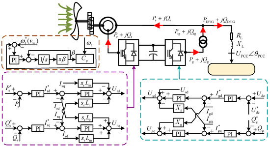
Figure 1.
Control model of the DFIG.
2.1. Linearized Model of the DFIG
In order to analyze the dynamic response characteristics of the rotor current in the DFIG, the rotor current component of the dq axis is regarded as a state variable. Based on the voltage equation and flux equation of the DFIG induction motor, the incremental equation of the rotor current is obtained [32]:
where Δ represents increment, Isd, Isq, Ird, and Irq are the stator and the rotor current of the dq axis, Usd, Usq, Urd, and Urq are the stator and the rotor voltage of the dq axis, wr is the rotor speed, ωB is the reference value of the speed, Lm is excitation reactance, Lss and Lrr are the stator and rotor side self-inductance, and Rs and Rr are the stator and rotor resistors.
When the power grid fails, the power balance is broken. The DC capacitor absorbs excess active power, causing overvoltage. The DC capacitor voltage increment equation is expressed as:
where C is the DC capacitor, Udc is the DC capacitor voltage, and Ugd, Ugq, Igd, and Igq are the dq axis components of the voltage and current on the grid side.
The rotor-side converter controls the output of the active and reactive power of the DFIG [33]. According to the control block diagram shown in Figure 1, both the rotor-side converter and the grid-side converter are double-loop control, that is, current inner loop and power outer loop control. The dq decoupling control is realized by introducing feedforward terms. The inner loop of rotor-side converter current is related to the rotor current. Terminal voltage drop requires multiple reactive power in a DFIG, and the increase in reactive power demand causes the increase in the rotor current Q-axis component reference value. The rotor-side converter control increment equation is expressed as:
where x6, x7, x8, and x9 are the intermediate variables; kp2, ki2, kp3, ki3, kp4, ki4, kp5, and ki5 are the ratio and integration coefficient of the rotor-side converter; and are reference values of the stator active and reactive power; and and are the reference values of the rotor dq axis current.
The DC capacitor voltage is controlled by the grid-side converter [34]. When the capacitor voltage fluctuates, the potential in the grid-side converter will change, thus driving the grid-side converter action to maintain the balance of the capacitor voltage. The grid-side converter control increment equation is expressed as:
where x10, x11, x12, and x13 are the intermediate variables; kp6, ki6, kp7, ki7, kp8, ki8, kp9, and ki9 are the ratio and integration coefficient of the grid-side converter; , , are the DC capacitor voltage and grid reactive power reference values; and are the current reference values of the dq axis on the network side; and XT is transformer reactance on the grid side.
With the component of the xy axis of the point of common coupling as input, and the concerned DFIG variable as output, the linearized model of DFIG can be expressed as:
where x is the state variable, A is the state matrix, B is the input matrix, C is the output matrix, u is the input variable, including Upccx and Upccy, and y is the output variable.
This paper aims to study the influence of changes in the point of common coupling voltage amplitude Upcc and phase θpcc on the output characteristics of the DFIG. The incremental equation above does not contain Upcc and θpcc, so it is necessary to establish the relationship between ΔUpcc, Δθpcc and ΔUpccx, ΔUpccy:
where B′ is the transformation matrix and Upccx and Upccy are components of the point of common coupling voltage in the xy coordinate system.
By combining (8) and (9), a small disturbance dynamic model with ΔUpcc and Δθpcc as inputs and the considered DFIG disturbance variables as outputs is obtained:
where Δu1 is the converted input variables, including ΔUpcc and Δθpcc.
2.2. Transfer Function Model Based on the Laplace Transform
As shown in (11) and Figure 2, when taking the rotor side current dq axis components Ird and Irq as outputs, the Laplace transform is applied to (10) to obtain the transfer function model of the DFIG.
where G11(s), G12(s), G21(s), and G22(s) are transfer functions and I is the identity matrix.
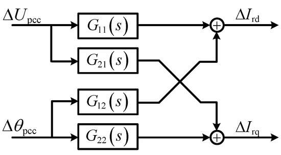
Figure 2.
Transfer function model of the DFIG.
To realize the decoupled control to the active and reactive powers, vector control is often applied to a DFIG. Thus, the rotor current includes the direct and the quadrature components, i.e., Ird and Irq. The magnitude of the rotor current is decided by both Ird and Irq; thus, the incremental form of the rotor current is given by those of its dq components (12). Violation of the upper limit of the rotor current limit or the lower limit of the stator voltage will activate the LVRT measures.
For the response characteristics analysis of other variables in the DFIG, such as DC capacitor voltage, the process of establishing the transfer function model is similar.
Figure 3 shows the phase variation in the point of common coupling in the power grid under different failure times. It can be seen that the phase oscillates at different fault times. The phase fluctuation in the point of common coupling is equivalent to the input signal acting on the DFIG, which causes the output response characteristics of the DFIG to change accordingly, and the output amplitude is related to the amplitude of phase oscillation. Therefore, it is necessary to study the effect of phase oscillation on the response characteristics of the DFIG variables. Equation (13) gives the expression of the DFIG input signal, taking into account voltage amplitude drop and the phase angle jump with its fluctuation phenomenon.
where ε(t) is the unit step function; t0 is the time when the simulated fault occurs; Us0 is the initial value of the voltage amplitude at the machine end; k1 is the voltage drop degree; w is the wave signal frequency; k2 is the degree of the phase jump; and A2 is the amplitude of the phase fluctuation signal.


Figure 3.
The change in the phase angle jump during a fault: (a) the fault lasts for 0.2 s; (b) the fault lasts for 0.8 s; (c) the fault lasts for 1 s; and (d) the fault lasts for 2 s.
The Laplace transform is applied to Equation (13) to obtain the frequency domain form of the input signal:
This input signal is combined with the transfer function describing the dynamic response relationship of the DFIG so that the response characteristics of the DFIG can be easily analyzed.
where L−1 is the inverse Laplace transform and y is the output variable of the DFIG.
3. The Reduced Model of the Transfer Function
In order to analyze the influence of input changes on the dynamic characteristics of the output in the time domain, it is necessary to perform an inverse Laplace transformation of the transfer function model. Since the DFIG is described by an 18-order detailed model, the order of the transfer function is relatively high, and its explicit expression in the time domain cannot be obtained directly by MATLAB (2017a). Therefore, the transfer function needs to be reduced.
Equation (11) contains multiple transfer functions. To show the reduction, this paper shows the reduction process of a single transfer function, so G11 is transformed into a state–space equation:
where A1∈Rn1×n1, B1∈Rn1×2, and C1∈R2×n1, where n1 is the order of the state–space equation corresponding to G11(s).
The real parts of the eigenvalues of the state matrix A1 are arranged in order from largest to smallest as follows:
The real part of the k-th eigenvalue obtained from the above arrangement has the following relationship:
Based on the Schur decomposition theorem, there is an orthogonal matrix U, and the state matrix A1 can be decomposed into an ordered real Schur:
where A11∈Rk×k, A14∈R(n1−k)×(n1−k), and λi(A11) = λi(A1), i = 1,2, …, k.
A similar transformation of S gives a block diagonal matrix V, where the similar transformation matrix H is expressed as Equation (21), x2∈Rk×(n1−k), HH−1 = In1.
The necessary condition for completing a similar transformation process is that x2 satisfies the Sylvester equation:
Under the condition T = UH, the original system F1 can be transformed into F2:
where x =Tr, At =T−1A1T, Bt =T−1B1, and Ct =C1T. Each coefficient matrix is denoted in the following form:
Since U is an orthogonal matrix and (22) is numerically reliable, the similarity transformation T = UH is numerically stable. Based on (24) and (25):
The following relations are used to synthesize the transfer function before and after transformation:
In (27), the original system F1 can be decomposed into the sum of independent subsystems. The dominant pole subsystem F3 is taken as the reduced order system, which can retain the dominant characteristics of F1. Its corresponding transmission function is expressed as G11(s)1, and G12(s)1, G21(s)1, and G22(s)1 can be obtained similarly.
By substituting the reduced transfer function into (15), the analytic expression of the output variable of the DFIG is obtained:
The phase angle jump and its fluctuation will impact the rotor current. Only taking the voltage drop degree as the criterion for rotor-side protection resistance switching will be overly optimistic when judging the operation of the DFIG, which may delay the rotor resistance switching time and fail to play a protective role in time. Figure 4 shows the rotor string resistance switching process under the action of different input signals, where ΔUs1 and ΔIra are the minimum increments of terminal voltage and rotor current when the rotor resistance is put into the DFIG, respectively, which are set as 0.7 p.u and 0.5 p.u. in this paper.
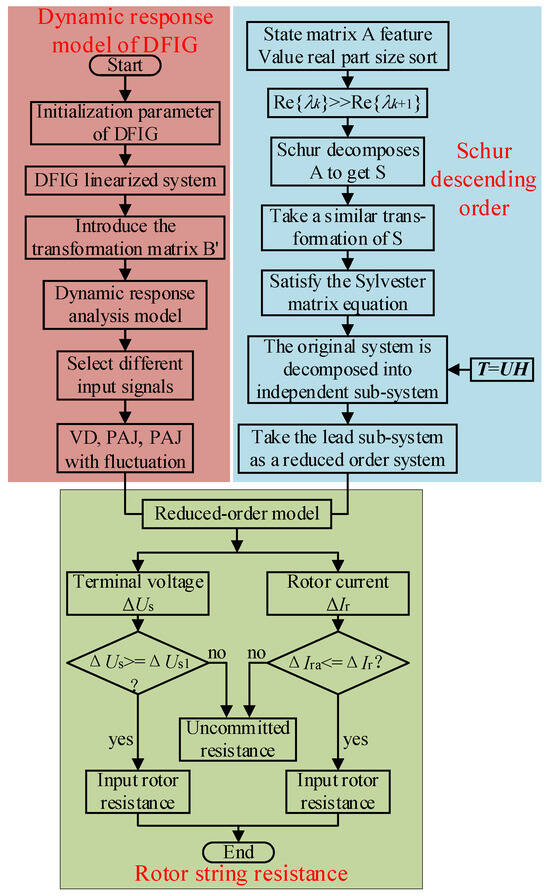
Figure 4.
Transfer function reduction and rotor string resistance switching process.
Grid faults result in lower voltage and higher rotor current of a DFIG terminal. To realize the LVRT, some measures need to be taken. In this paper, the rotor series resistance is adopted, and Equation (30) is the casting criterion of rotor resistance. When the terminal voltage of the DFIG is lower or the rotor current is higher than the allowable value, the rotor resistor will be put into operation.
Under different input signals, the DFIG terminal voltage and rotor current have different response characteristics, and the input of rotor series resistance is different. Thus, the key factors affecting the effectiveness of LVRT measures can be found.
where ΔIra is the rotor current increment amplitude. It should be noted that there is a logical relationship between the terminal voltage criterion and the rotor current criterion, and the resistance can be put into the rotor side if either criterion is met.
4. Numerical Validation
Based on the linearization model of the DFIG, a program was written in MATLAB (2017a) to verify the accuracy of the transfer function reduction model. On this basis, the response characteristics of DFIG under different input signals and the effectiveness of the rotor string resistance switching strategy were analyzed. The DFIG capacity was 1.5 MW and the wind speed was 9 m/s.
4.1. Accuracy Verification of the Reduced-Order Model of the Transfer Function
Based on the transfer function model established in Section 2.2, which takes the component of the rotor current as the output variable, Figure 5 shows the Bode diagrams before and after reducing the transfer function.
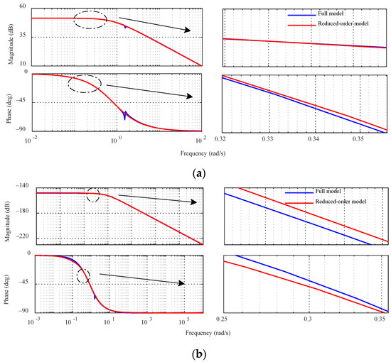
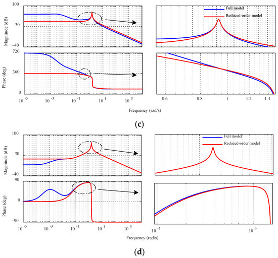
Figure 5.
Bode plots before and after DFIG reduction: (a) G11(s); (b) G12(s); (c) G21(s); and (d) G22(s).
A voltage drop or phase angle jump may cause oscillations in the high to medium frequency range of a DFIG. By locally enlarging the Bode diagrams before and after reducing the transfer function of the DFIG system, it can be seen that the response characteristics of the frequency bands considered in this paper are basically the same, which verifies the effectiveness of the reduction method in this paper.
Figure 6 gives the distribution of poles before and after the order reduction of the transfer function. It can be seen that the transfer function can retain the dominant poles of the original transfer function after order reduction. The frequency response characteristics of the Bode diagrams of the transfer function in high- and low-frequency bands are related to the distance between the poles and the real axis. High-frequency information corresponds to poles that are farther away from the real axis and, conversely, to low-frequency information. The poles excluded by reducing the transfer function are close to the real axis, so it is easy to cause low-frequency distortion of the Bode diagrams.


Figure 6.
Pole distribution before and after transfer function reduction: (a) G11(s); (b) G12(s); (c) G21(s); and (d) G22(s).
After reducing the transfer function, the Bode diagrams can remain undistorted in the frequency band above 10−1 rad/s, and the corresponding oscillation response period of this frequency point exceeds 60 s. However, the actual oscillation response time of the DFIG during low-voltage crossing is much less than 60 s, so the low-frequency distortion below 10−1 rad/s does not affect the research in the middle and high-frequency bands in this paper.
Equations (31) through (34) give the reduced-order transfer function of the rotor current and DC capacitor voltage with respect to the point of common coupling voltage and the phase.
Although the above transfer function was reduced, it is still difficult to perform the inverse Laplace transformation directly. The transfer function is written as a sum of terms by means of partial fraction expansion:
The time domain expression of the rotor current and DC capacitor voltage is obtained by the Laplace inverse transformation of the above equation.
The output variable expression of the DFIG is obtained based on the reduced-order transfer function, which is the analytic result obtained based on the linearized model. This paper compares the time-domain simulation of the actual nonlinear system with the output variable analytic expression results of the DFIG, and finds that the analytic expression results of the output variable of the DFIG are consistent with the time-domain simulation, which verifies that the linearized model can represent the actual system correctly. The simulation results are shown in Figure 7. At t = 5 s, the voltage magnitude of the point of common coupling is set to change from 1 p.u. to 0.8 p.u., when t = 10 s, the voltage magnitude is restored to the initial value, and the simulation time is 20 s.
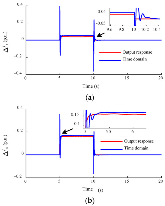
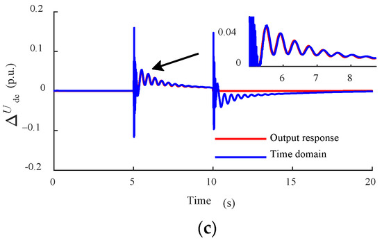
Figure 7.
Validation of the reduced-order modeling of the output response: (a) rotor current ΔIr; (b) stator current ΔIs; and (c) DC capacitor voltage ΔUdc.
Table 1 shows a comparison of the simulation time between the two models. The time-domain simulation time is close to 6 s, while the output response time only accounts for about 4% of the time-domain simulation. Therefore, the operation efficiency of the output response is higher and it is more convenient for practical application.

Table 1.
Comparison of output response and time-domain simulation.
4.2. DFIG Response Characteristic Analysis with the Phase Angle Jump and Its Fluctuation
Figure 8 shows the response characteristics of the DFIG under different input signals. The input signals include voltage drop (VD), phase angle jump (PAJ) with its fluctuation, and various combinations of them. It can be seen from the simulation results that the changes in different input variables have different degrees of influence on each output variable. As for the response characteristics of ΔUdc and ΔIg, compared with voltage drop, phase angle jump has a greater impact on them, and ΔUdc and ΔIg increase slightly after taking into account the fluctuation factor. For ΔIs and ΔIr, the voltage drop and phase angle jump with its fluctuation have a great influence on the constant rotor current, among which the phase angle jump with its fluctuation has the most obvious influence on the dynamic response of the DFIG. When all factors are taken into account, the output of ΔIs and ΔIr is the largest, indicating that the phase angle jump and its fluctuation factor cannot be ignored when analyzing the actual dynamic response characteristics of DFIG.


Figure 8.
Comparison of DFIG response characteristics: (a) DC capacitor voltage ΔUdc; (b) grid-side current ΔIg; (c) rotor current ΔIr; and (d) stator current ΔIs.
4.3. Validity Verification of Rotor String Resistance Switching Strategy
In order to suppress the rotor current and the DC capacitor voltage during the fault period, a protection resistor is set on the rotor side. When the terminal voltage drop and the rotor current reach the protection resistance enabling criterion, the protection resistor will be inserted into the rotor loop to inhibit the rotor current and the DC capacitor voltage. Figure 9 shows the response of the DFIG rotor current and DC capacitance voltage with additional rotor string resistance protection under different input signals. When voltage drop alone is considered, the terminal voltage drop value is 0.18 p.u. and the rotor current is 0.37 p.u., which is less than the rotor resistance input criterion. The rotor protection resistance does not work, so its response is the same as that considering only the voltage drop case. When the voltage drops, the phase angle jump and its fluctuation are considered at the same time, although the terminal voltage drop value does not meet the rotor resistance switching criterion. The rotor current oscillation peak value is 0.49 p.u., which meets the switching criterion. At this time, the rotor resistance is put into the rotor side, and the rotor current and DC capacitor voltage are significantly reduced, thus playing a protective role.

Figure 9.
The effectiveness of low-voltage ride-through measures before and after taking into account the phase angle jump: (a) rotor current and (b) DC capacitor voltage.
In fact, the rotor current is the result of the voltage drop and phase angle jump and its fluctuation. The amplitude of phase fluctuation affects the amplitude of rotor current oscillation. If the oscillation amplitude is too large, the rotor windings of the DFIG will be damaged. Therefore, for various measures of LVRT, it is necessary to consider the impact of the phase angle jump and phase fluctuation on the response characteristics of DFIGs so that the protection device can be more in line with the actual application scenario.
As shown in Figure 10, the time-domain simulation is used to further verify the effectiveness of the rotor string resistance strategy. The fault duration is set at 0.2 s and the total simulation duration is 10 s. As can be seen from the time-domain simulation results, after the LVRT measure is put into operation, the DFIG rotor current and DC capacitor voltage can be suppressed, and a part of reactive power can be provided to the power grid, which is conducive to the voltage recovery of the power grid and the safe operation of the DFIG.
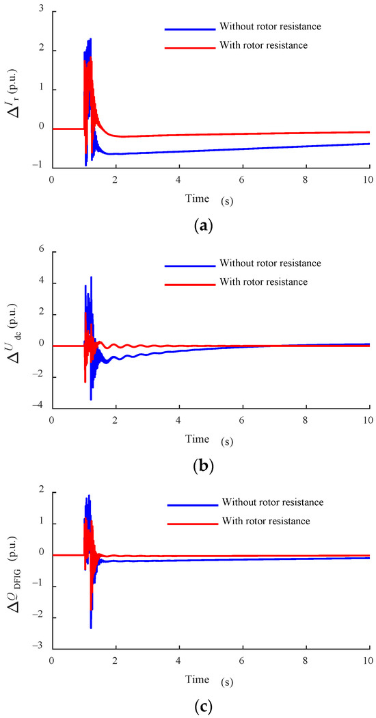
Figure 10.
The dynamic response of the DFIG before and after the low-voltage ride-through measure is put into operation: (a) rotor current; (b) DC capacitor voltage; and (c) DFIG reactive power.
5. Conclusions
In this paper, a DFIG model is linearized to propose its transfer function model. A reduced model for the transfer function of the DFIG using Schur decomposition is proposed, and the analytical expression of the output variables of the DFIG with the phase angle jump is derived by the inverse Laplace transformation to judge the necessity of the LVRT measures. The mathematical modeling and the numerical results show the following:
- (1)
- The model reduction method based on Schur decomposition maintains the dominant characteristics of the DFIG, and the response characteristics within the middle- and high-frequency bands are consistent with the actual response;
- (2)
- The response curves of the stator current, the rotor current, and the DC voltage based on the reduced transfer function are consistent with those of the time-domain simulation results, which verifies the accuracy of the proposed reduced transfer function of the DFIG. Compared with the time domain simulation, the transfer function is computationally more efficient, and the simulation time is about 4% of that using the time domain simulation;
- (3)
- The rotor current of the DFIG and the PCC voltage with phase angle jump and its fluctuation increase significantly compared with those with the voltage drop only. Hence, a large phase angle jump will threaten the security of the DFIG and the integrated power system. The existing LVRT measures against a voltage drop should be improved by considering the negative impact of the phase angle jump.
Author Contributions
Conceptualization and funding acquisition: S.L., P.F., Z.W. and J.X. Validation, writing—original draft, writing—review and editing, resources and software, and data curation: S.L., Z.W., P.F., J.X., Y.S. and X.G. All authors have read and agreed to the published version of the manuscript.
Funding
This research was funded by State Grid Anhui Electric Power Co., Ltd., under grant 521209240007.
Data Availability Statement
The original contributions presented in this study are included in this article. Further inquiries can be directed to the corresponding author.
Conflicts of Interest
Authors Peiru Feng, Jiayin Xu, Yuming Shen and Xu Gui were employed by the State Grid Anhui Electric Power Co., Ltd. The remaining authors declare that the research was conducted in the absence of any commercial or financial relationships that could be construed as a potential conflict of interest.
References
- Gao, X.; Xie, Z.; Li, M.; Yang, S.; Zhang, X. Analysis and mitigation of electromechanical oscillations in drivetrain for hybrid synchronization control of DFIG-based wind turbines. IEEE Trans. Power Electron. 2024, 39, 3002–3013. [Google Scholar] [CrossRef]
- Saha, S.; Saleem, M.I.; Roy, T.K. Impact of high penetration of renewable energy sources on grid frequency behaviour. Int. J. Electr. Power Energy Syst. 2023, 145, 142–615. [Google Scholar] [CrossRef]
- Alsmadi, Y.M.; Xu, L.; Blaabjerg, F.; Ortega, A.J.P.; Abdelaziz, A.Y.; Wang, A.; Albataineh, Z. Detailed investigation and performance improvement of the dynamic behavior of grid-connected DFIG-based wind turbines under LVRT conditions. IEEE Trans. Ind. Appl. 2018, 54, 4795–4812. [Google Scholar] [CrossRef]
- Loulijat, A.; Ababssi, N.; Mohamed, M. Kalman observer contribution to a second order sliding mode control for wind turbine based on DFIG during the network voltage dip. Int. J. Intell. Eng. Syst. 2021, 14, 88–101. [Google Scholar] [CrossRef]
- Qin, B.; Li, H.; Zhou, X.; Li, J.; Liu, W. Low-voltage ride-through techniques in DFIG-Based wind turbines: A Review. Appl. Sci. 2020, 10, 2154. [Google Scholar] [CrossRef]
- Tian, X.; Li, G.; Chi, Y. Voltage phase angle jump characteristic of DFIGs in case of weak grid connection and grid fault. J. Mod. Power Syst. Clean Energy 2016, 4, 256–264. [Google Scholar] [CrossRef]
- Reddy, K.; Saha, A.K. A heuristic approach to optimal crowbar setting and low voltage ride through of a doubly fed induction generator. Energies 2022, 15, 9307. [Google Scholar] [CrossRef]
- Jiang, D.; Yu, W.; Wang, J.; Zhong, G.; Zhou, Z. Dynamic analysis of DFIG fault detection and its suppression using sliding mode control. IEEE J. Emerg. Sel. Top. Power Electron. 2023, 11, 643–656. [Google Scholar] [CrossRef]
- Yin, J.; Huang, X.; Qian, W. Analysis and research on short-circuit current characteristics and grid access faults of wind farms with multi-type fans. Energy Rep. 2024, 11, 1161–1170. [Google Scholar] [CrossRef]
- Wang, Y.; Bollen, M.H.J.; Xiao, X.-Y. Calculation of the phase-angle jump for voltage dips in three-phase systems. IEEE Trans. Power Deliv. 2015, 30, 480–487. [Google Scholar] [CrossRef]
- Ren, J.; Xiao, X.; Zheng, Z.; Wang, Y.; Ma, Z.; Liu, K. Impact of phase angle jump on DFIG under LVRT conditions: Challenges and recommendations. IEEE Trans. Power Deliv. 2021, 36, 3701–3713. [Google Scholar] [CrossRef]
- Geng, H.; Liu, C.; Yang, G. LVRT capability of DFIG-based WECS under asymmetrical grid fault condition. IEEE Trans. Ind. Electron. 2013, 60, 2495–2509. [Google Scholar] [CrossRef]
- Ren, J.; Xiao, X.; Liu, Y.; Zheng, Z.; Chen, W. Impact of PAJ with varying POW in voltage sag on rotor over-voltage in DFIG-based wind generator. CIRED-Open Access Proc. J. 2017, 2017, 715–718. [Google Scholar] [CrossRef][Green Version]
- Tian, X.; Chi, Y.; Wang, W.; Li, G.; Tang, H.; Wang, Z. Transient characteristics and adaptive fault ride through control strategy of DFIGs considering voltage phase angle jump. J. Mod. Power Syst. Clean Energy 2017, 5, 757–766. [Google Scholar] [CrossRef]
- Taul, M.; Wang, X.; Davari, P.; Blaabjerg, F. Robust fault ride through of converter-based generation during severe faults with phase jumps. IEEE Trans. Ind. Appl. 2020, 56, 570–583. [Google Scholar] [CrossRef]
- Pan, X.; Liang, W.; Guo, J.; Sun, X.; Chen, H.; He, D. Parameter estimation by considering both voltage dip and phase angle jump for DFIG-based WTGs in distribution grids. IEEE Trans. Sustain. Energy 2024. [Google Scholar] [CrossRef]
- Liu, X.; Zhang, Z.; Liu, Y.; Liu, Z.; Su, M.; Li, C.; Ge, L.; Zhang, X.; Wang, P. Fault current unified calculation method for whole process fault ride-through of DFIG-based wind farms. IEEE Trans. Smart Grid 2024, 15, 485–503. [Google Scholar] [CrossRef]
- Xiong, X.; Luo, B.; Li, L.; Sun, Z.; Blaabjerg, F. Impedance reshaping method of DFIG system based on compensating rotor current dynamic to eliminate PLL influence. IEEE Trans. Power Electron. 2024, 39, 4006–4016. [Google Scholar] [CrossRef]
- Zhang, D.; Ma, J.; Wang, S.; Ji, Y.; Qu, C. Analysis on the characteristic of the instantaneous inrush current of brushless doubly fed induction generator. IEEE Trans. Energy Convers. 2023, 38, 747–758. [Google Scholar] [CrossRef]
- Yang, Y.; Zhu, D.; Zhou, D.; Zou, X.; Hu, J.; Kang, Y. Synchronization instability mechanism and damping enhancement control for DFIG-based wind turbine during grid faults. IEEE Trans. Power Electron. 2023, 38, 12104–12115. [Google Scholar] [CrossRef]
- Du, C.; Du, X.; Tong, C. SSR Stable Wind speed range quantification for DFIG-based wind power conversion system considering frequency coupling. IEEE Trans. Sustain. Energy 2023, 14, 125–139. [Google Scholar] [CrossRef]
- Yang, H.; Yuan, X. Modeling and analyzing the effect of frequency variation on weak grid-connected VSC system stability in DC voltage control timescale. Energies 2019, 12, 4458. [Google Scholar] [CrossRef]
- Abo-Khalil, A.G.; Alghamdi, A.; Tlili, I.; Eltamaly, A.M. Current controller design for DFIG-based wind turbines using state feedback control. IET Renew. Power Gener. 2019, 13, 1938–1948. [Google Scholar] [CrossRef]
- Zhang, Y.; Tang, W.; Fang, Y.; Liu, Y.; He, W.; Li, Y. Reduced-order model of frequency response including PLL-based DFIG wind turbine. In Proceedings of the 2023 2nd International Conference on Smart Grids and Energy Systems (SGES), Guangzhou, China, 25–27 August 2023; pp. 156–162. [Google Scholar]
- Huang, J.; Sang, S.; Zhang, L.; Xue, X.; Sun, T. Control of a variable-impedance fault current limiter to assist low-voltage ride-through of doubly fed induction generators. Electronics 2021, 10, 2364. [Google Scholar] [CrossRef]
- Kaloi, G.S.; Baloch, M.H.; Kumar, M.; Soomro, D.M.; Chauhdary, S.T.; Memon, A.A.; Ishak, D. An LVRT scheme for grid connected DFIG based WECS using state feedback linearization control technique. Electronics 2019, 8, 777. [Google Scholar] [CrossRef]
- Sabzevari, K.; Khosravi, N.; Abdelghany, M. Low-voltage ride-through capability in a DFIG using FO-PID and RCO techniques under symmetrical and asymmetrical faults. Sci. Rep. 2023, 13, 17534. [Google Scholar] [CrossRef]
- Mohsen, G.; Mehdi, F.; Babak, M.; Farzad, G. Power flow management and LVRT enhancement by using multi-functional capacitive bridge-type fault current limiter in DFIG system. Int. J. Electr. Power Energy Syst. 2023, 148, 108810. [Google Scholar]
- Zhou, N.; Ma, H.; Chen, J.; Fang, Q.; Jiang, Z.; Li, C. Equivalent modeling of LVRT characteristics for centralized DFIG wind farms based on PSO and DBSCAN. Energies 2023, 16, 2551. [Google Scholar] [CrossRef]
- Xian, L.; Wu, L.; Li, W.; Wu, Y.; Xie, X. Enhancing FRT capability of DFIG based on RC-crowbar considering the resonance and matching control strategies for different fault degrees. Electr. Power Syst. Res. 2024, 232, 110434. [Google Scholar] [CrossRef]
- Li, S.; Fang, T.; Zhang, H.; Ye, J. Damping the electromechanical oscillation modes (EOMs) in DFIG-integrated power systems with sensitivity analysis and optimization to outputs of SGs. Int. J. Electr. Power Energy Syst. 2022, 135, 107565. [Google Scholar] [CrossRef]
- Li, S. Low-frequency oscillations of wind power systems caused by doubly-fed induction generators. Renew. Energy 2017, 104, 129–138. [Google Scholar] [CrossRef]
- Liu, X.; Zhang, P.; Deng, X.; Sun, D. Hierarchical overvoltage predictive control scheme for a DFIG-based wind farm. Electr. Power Syst. Res. 2023, 217, 109172. [Google Scholar] [CrossRef]
- Yuan, H.; Wang, D.; Zhou, X. Frequency support of DFIG-based wind turbine via virtual synchronous control of inner voltage vector. Electr. Power Syst. Res. 2023, 225, 109823. [Google Scholar] [CrossRef]
Disclaimer/Publisher’s Note: The statements, opinions and data contained in all publications are solely those of the individual author(s) and contributor(s) and not of MDPI and/or the editor(s). MDPI and/or the editor(s) disclaim responsibility for any injury to people or property resulting from any ideas, methods, instructions or products referred to in the content. |
© 2024 by the authors. Licensee MDPI, Basel, Switzerland. This article is an open access article distributed under the terms and conditions of the Creative Commons Attribution (CC BY) license (https://creativecommons.org/licenses/by/4.0/).