Appendix A
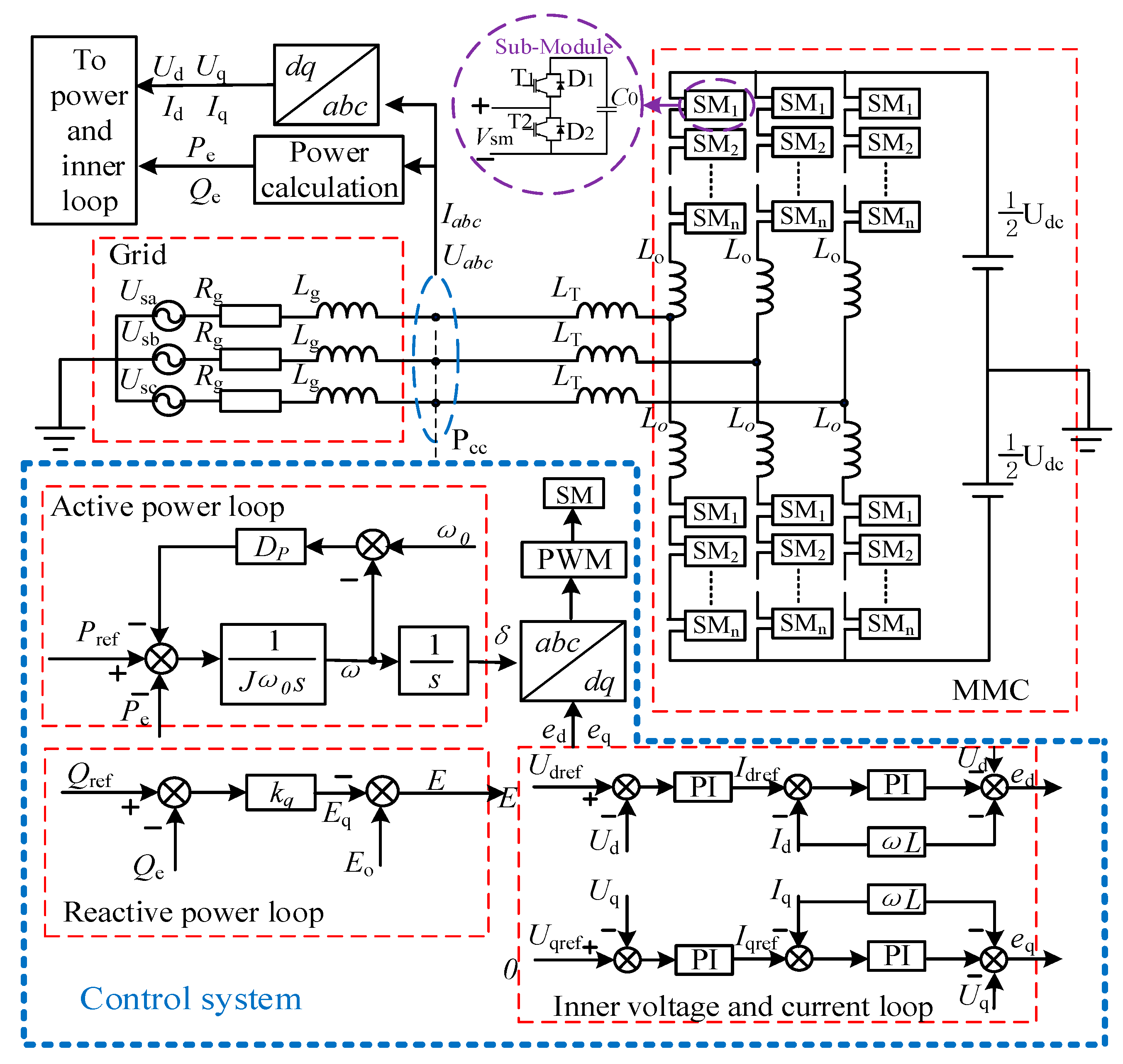
A full-order model of MMC-VSG includes the following 5 parts:
Figure A1.
MMC-VSG state space model block diagram.
Figure A1.
MMC-VSG state space model block diagram.
The calculation formulas for active and reactive power outputted from grid-connected MMC are
The state equations for active and reactive power control can be written as
and
The small signal state space model of the power controller can be obtained by linearizing Equations (A2) and (A3) at the steady-state operating point, namely
Among them, Ap is the system matrix, Bp is the input matrix, and Cp is the output matrix. (The following ABC matrices all represent the same meaning.)
The inner voltage control loop is achieved through PI, which can be expressed as
and
In Equations (A6) and (A7), we have
In Equations (A6) and (A7), linearization is performed at the steady-state operating point to obtain the small signal state space model of the voltage loop:
And by rewriting Equations (A8) and (A9) using spatial vectors, the vector expression of the voltage loop can be obtained by
wherein
.
The current inner loop control is also achieved through PI, which can be expressed as
and
In Equations (A11) and (A12), we have
A small signal state space model of the current loop can be obtained by linearizing at the steady-state operating point as
By rewriting Equations (A13) and (A14) using space vectors, the vector expression for the current loop can be obtained as
wherein
,
.
Considering the voltage modulation wave outputs to the flexible DC sub-module after being modulated by the nearest level, and considering the delay effect, the actual and the reference value of the grid-connected transformer voltage satisfy Equation (A15), where
Ti represents the time constant of the inertia link:
The small signal state space model written in (A16) is
Equation (A17) is rewritten using spatial vectors, and the vector expression can be obtained as
The differential equation for a grid-connected transformer can be written as
Equation (A19) is linearized at the steady-state operating point and written as a small signal state space model:
The frequency domain form of Equation (A19) can be represented and rewritten using spatial vectors to obtain the vector model of the leakage inductance
Similarly, the grid loop can be written in the
dq axis coordinates.
In the formula,
ugd and
ugq are the
dq axis voltage on the grid side. Combining the grid-connected transformer (A19) and the grid loop (A22) can be obtained by
By linearizing (A22), we can obtain
The grid voltage can be expressed as
ugd =
Ugcos
δ,
ugq = -
Ugsin
δ, and (A24) can be rewritten as
By using space vector rewriting for Equation (A25), the vector model of the output circuit loop can be obtained by
The total space vector equation of MMC-VSG can be rewritten as
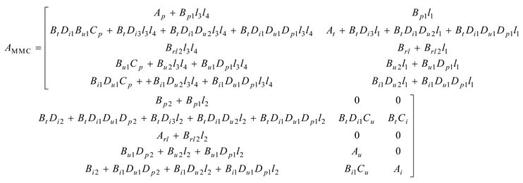
The full-order small signal model of MMC-VSG can be obtained as
wherein
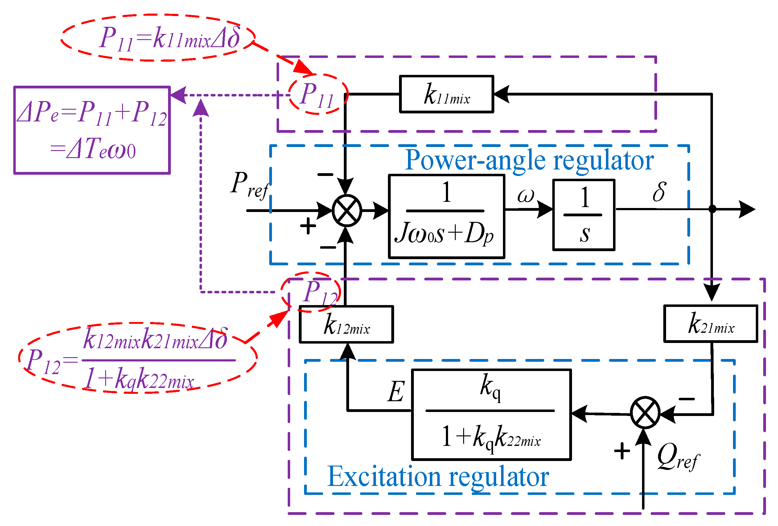
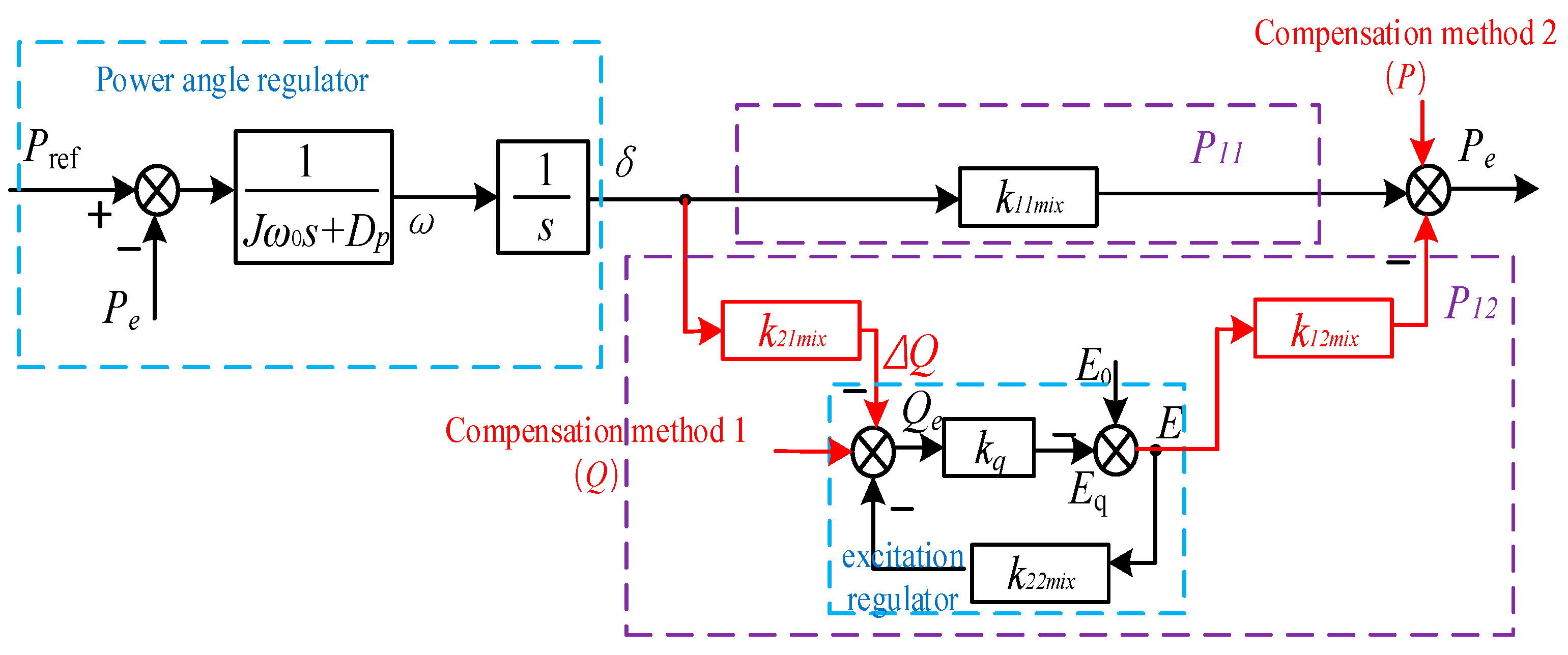
Figure 5 shows that the coupled reactive power (negative torque) to be compensated is ∆
Q =
k21mix∆
δ. According to
Table 1 and
Figure 5, it can be obtained that
The coupling voltage that needs to be compensated can be obtained by moving the coupling circuit node forward:
The reactive power to be compensated is a function of
∆δ, which is associated with synchronous torque, while the excitation VPSS is a function of damping torque. Therefore, while compensating for the damping torque of the excitation VPSS, the synchronous torque of the system can be added to achieve a decoupling of MMC-VSG dynamic active and reactive power.
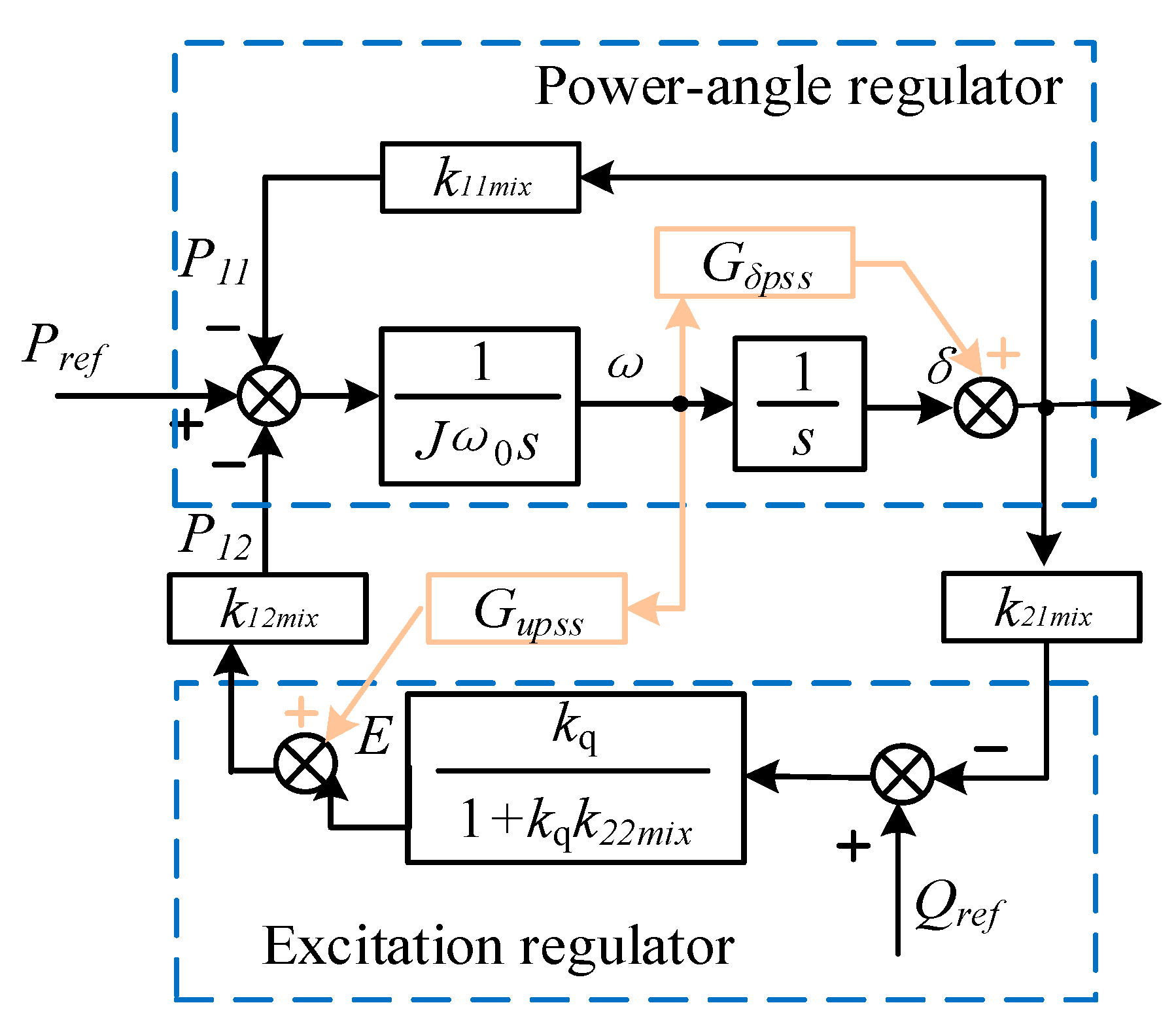
Figure A2 shows the phase compensation of the excitation VPSS, and Equation (A30) can be written as
So, the transfer function of the synchronous torque in decoupling active/reactive power for the excitation VPSS can be induced as
The Phillips−Heffron equation of state with the excitation VPSS can be expressed in the following form:
The input parameters Δ
u = [Δ
Pref Δ
Qref]
T and Δ
uupss =
GupssΔ
y = [0
GupssΔ
ω]
T output Δ
y = [0 Δ
ω]
T. The state variable is Δ
x = [Δ
δ Δ
ω]
T, and it can be calculated that
The transfer function of the excitation VPSS can be written as
Figure A2.
Principle of Phase Compensation.
Figure A2.
Principle of Phase Compensation.
According to the previous text, the total transfer function of the excitation VPSS is
Let
and Δ
uupss can be expressed with Δ
M2 as
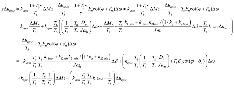
Equations (A34) and (A35) can be written as (Δ
Pref = 0, Δ
Qref = 0)
Combining Equations (A36) and (A37), the Phillips–Heffron expression with the excitation VPSS can be obtained as
where
If one lets the transfer function from Δ
uupss to Δ
Tupss be
Fupss (s), it can be concluded from
Figure 5 that
Thus, the torque caused by the excitation VPSS is
Among these, Δ
Tupss_δ(
s) is the synchronous torque caused by the excitation VPSS, and Δ
Tupss_ω(
s) is the damping torque caused by the excitation VPSS. Furthermore, the state equation of the MMC-VSG with the excitation VPSS in (17) can be derived as
The total MMC-VSG damping torque is
When is positive, the damping component of the system will be compensated.
When the excitation VPSS is introduced, the oscillation mode of the system is
λS_upss =
ζs_upss ±
jωs_upss. According to Equation (A41), the real part of the oscillation mode after introducing the excitation VPSS can be obtained by
Based on Equation (17), the real part of the oscillation mode before introducing the VPSS is
According to
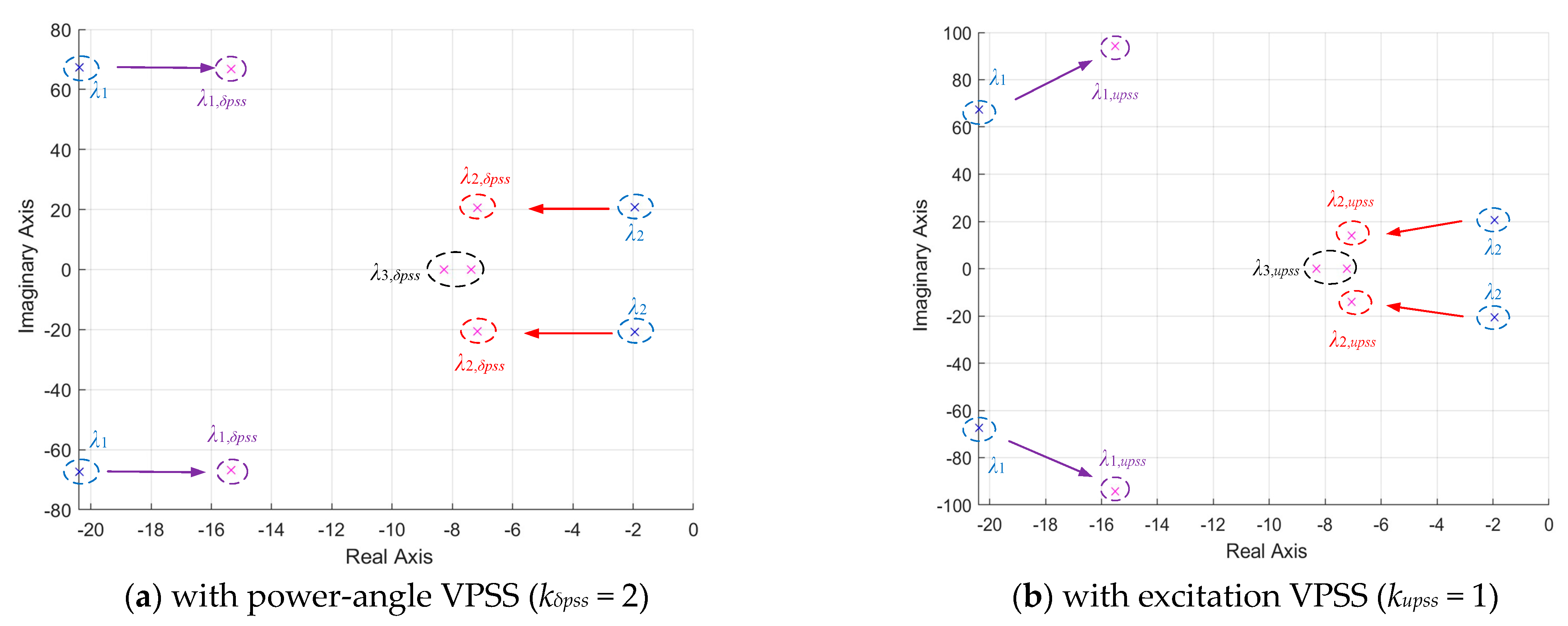
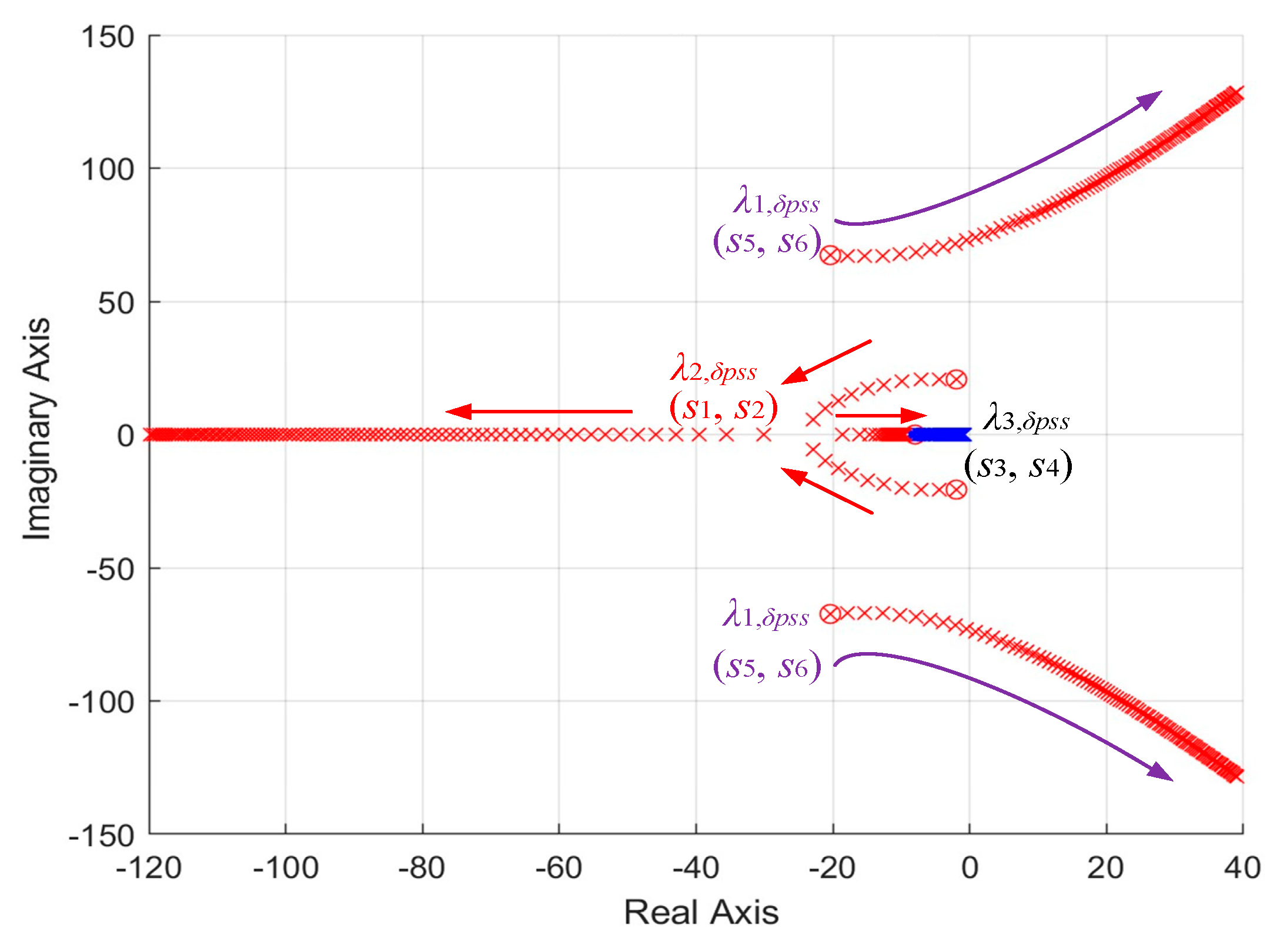
Table 4, when the MMC-VSG is operated without the VPSS, the eigenvalues representing the oscillation modes of the original system are −20.3886 ± j67.3457 and −1.9538 ± j20.6857, respectively. The damping ratio of Mode 2 is much smaller than that of Mode 1, leading to a smaller stability margin. Therefore, in our study, the parameter settings are mainly focused on Mode 2. In addition, when the MMC-VSG is operated without the VPSS, we have
λ2 = −1.9538 ± j20.6857, and we set the target eigenvalues of the oscillation mode to
λ’2 = −6.9538 ± j20.6857. We can get ζ
s_upss = −6.9538 and ζ
s = −1.9538. Then
Tupss_ω can be calculated by using (A44) minus (A43); also, if the phase angle can be calculated as −5.38°, the phase angle should be equal to the operation case with the VPSS, and as the time constants
T5 and
T7 are equal to 0.09,
T6 and
T8 can be calculated with the phase angle of −5.38°. When
λ2= −1.9538 ± j20.6857 is adopted as the target eigenvalue,
T6 and
T8 can be calculated, which is equal to 0.2. Then, when all these parameters are substituted into (A40), the key parameter
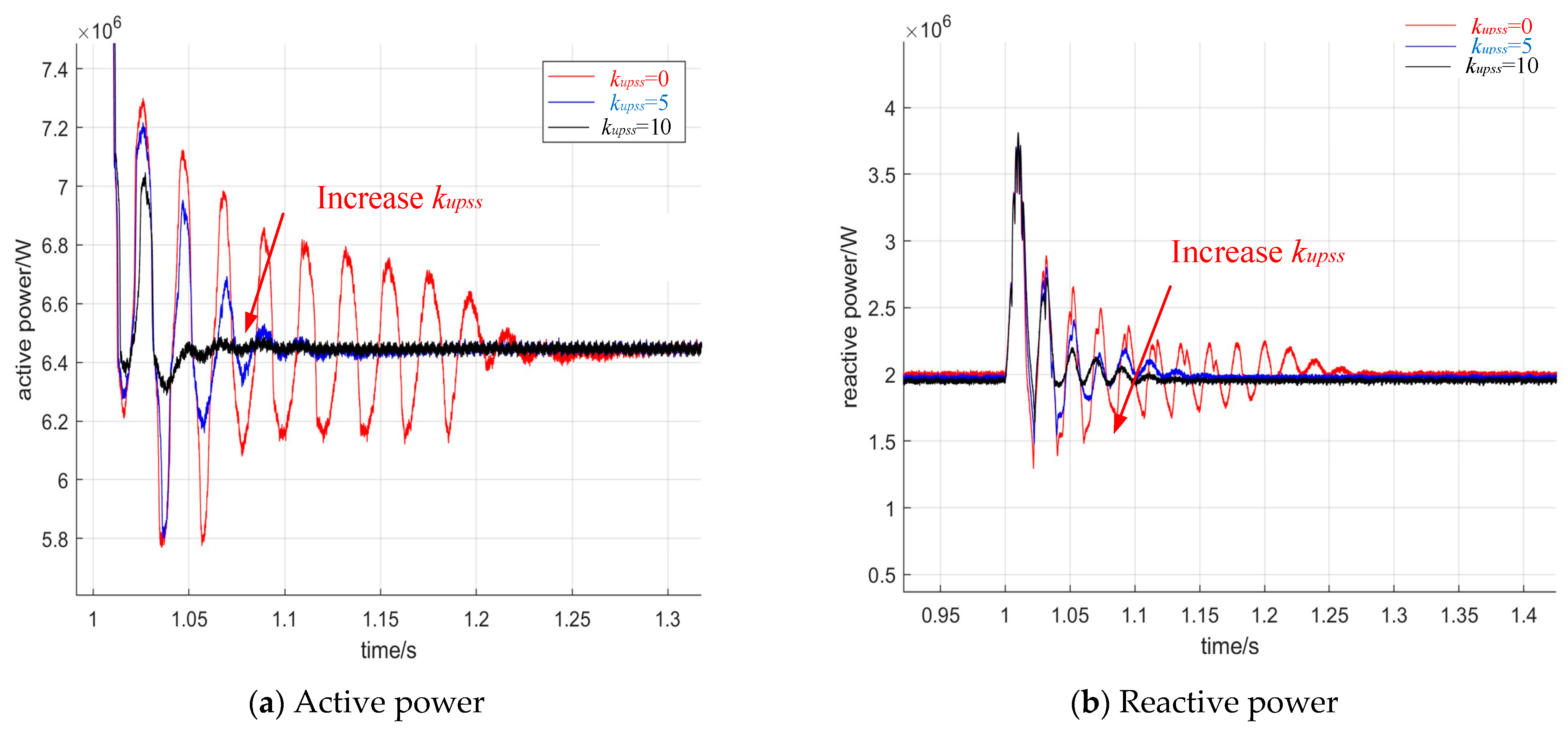
kupss = 0.95 can be obtained.
The expression of the Phillips−Heffron equation with the power-angle VPSS can be written as
Where the input parameters are Δ
u = [Δ
Pref Δ
Qref]
T, Δ
uδpss =
GδpssΔ
y = [0
GδpssΔ
ω]
T, and Δ
y = [0 Δ
ω]
T, the state variable is Δ
x = [Δ
δ Δ
ω]
T, and it can be calculated that
The expression of the Phillips–Heffron equation of state can be simplified as
where
The transfer function of the power-angle VPSS is .
So, Δ
uδpss can be written as
If we let
, Δ
uδpss can be expressed with Δ
M as
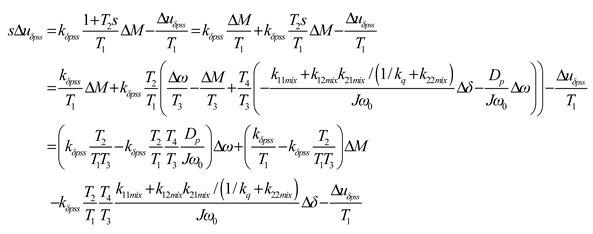
Equation (A41) and (A42) can be written as (Δ
Pref = 0, Δ
Qref = 0)
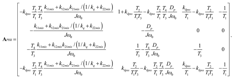
Combing Equations (A49) and (A50), the Phillips–Heffron expression with the power-angle VPSS can be obtained by
where
The time constants T1 toT4 and kδpss can be obtained with the same method of the excitation VPSS.

