Abstract
Compared to the AC counterpart, the DC shore power system provides a significant advantage of efficient power supply from renewable sources to ships and onshore loads. Super-capacitors serve as key energy storage units in such a system to buffer the power fluctuations and collect the regenerative energy. However, the ultra-wide voltage range of super-capacitors imposes a significant challenge in the topology selection and efficiency optimization of the interfacing isolated bidirectional DC–DC converter. To tackle this challenge, this paper analyzes and compares two promising converter topologies, which are a configurable modular two-level dual-active bridge (CM-2L-DAB) and a three-level dual-active bridge (3L-DAB). To facilitate an ultra-wide voltage range, extended phase-shift (EPS) modulation in conjunction with the topology reconfiguration is analyzed for the CM-2L-DAB, while a hybrid modulation scheme is proposed for the 3L-DAB. A unified design approach is provided for both topologies, which also yields to the power loss modeling. On this basis, the CM-2L-DAB and 3L-DAB are thoroughly compared in terms of the modulation schemes, current stress, soft-switching operation, power conversion efficiency, material usage, closed-loop control scheme, and reliability. A prominent conclusion can be drawn that the CM-2L-DAB provides a higher efficiency than the 3L-DAB over the whole voltage range, but it relies on additional relays to reconfigure its topology which results in lower reliability and dynamic performance than the 3L-DAB.
1. Introduction
Nowadays, the transportation sector has been a major source of greenhouse gas and carbon emission globally [1]. Taking the docked ships in the harbor for example, the shipboard power supply mostly relies on the diesel generator which consumes more fuel and produces more carbon emission than in the state of navigation [2]. This makes the shore-to-ship power technology, deploying the shore-based power, especially the renewables, to supply the docked ships, highly attractive to decarbonize shipping transportation [3,4]. Therefore, there is a high demand for a renewable and efficient shore power system that can integrate the public grid, photovoltaics (PV), wind turbines, shipboard energy storage, and loads in a single system, as illustrated in Figure 1. In such a system, the shore-based energy storage, such as a super-capacitor, also plays a key role in buffering the power fluctuation of the renewables and recycling the power from the regenerative loads [5]. Compared to the AC counterpart, the DC shore power system eliminates the additional DC–AC and AC–DC power conversion stages that are unnecessary for the DC-internal sources and loads, which reduces the investment cost and improves the system efficiency [6].
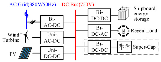
Figure 1.
DC shore power system.
In the DC shore power system, the bidirectional isolated DC–DC converter is a key enabling component to interconnect the super-capacitor and the shipboard battery storage system to the DC bus. Among others, the dual-active bridge (DAB) converter and CLLC resonant converter stand out as the most popular topologies due to their bidirectional power transfer capability and soft-switching characteristic [7,8,9,10]. Compared to the CLLC, the DAB converter requires less passive components and has a wider voltage range and higher power rating [11,12,13]. Thus, the DAB converter is preferred in the super-capacitor charging application. However, the wide voltage range of a high-power super-capacitor imposes high-voltage stress on the semiconductor devices, which makes the conventional two-level DAB topology inappropriate.
To adapt to the wide voltage range with lower voltage switches, two multi-level DAB topologies are further considered. The configurable modular two-level DAB converter (CM-2L-DAB) is a promising topology that is proposed in [14]. It connects two DAB modules in either input-parallel output-series (IPOS) or input-parallel output-parallel (IPOP) using relays. Due to the reconfigurability, the topology can adapt to a very wide voltage range and maintain a high efficiency using the modulation scheme of the 2L-DAB converter [15,16,17,18]. However, the modular structure inevitably increases the number of components.
To keep a low number of components, the three-level DAB (3L-DAB) converter is proposed in [19,20], where the three-level neutral-point-clamped (3L-NPC) bridge is employed on the high-voltage side. Compared to the 2L-bridge, the 3L-NPC bridge provides an additional degree-of-freedom (DoF) in the modulation, which can be utilized to optimize the efficiency of the DAB converter [21,22,23,24,25]. However, the modulation strategy is more complicated especially considering the wide voltage range.
So far, there has been extensive research on the optimal modulation schemes on the 2L-DAB and 3L-DAB converter separately [26]. However, the different modulation characteristic of the CM-2L-DAB and the 3L-DAB have never been thoroughly compared considering the wide voltage range of the super-capacitor. Moreover, no unified design approach can be used for these two topologies to quantify the difference in the total rating of the switches and the passive components. Therefore, it is difficult to evaluate and compare their performance and select the more suitable topology for the targeted application.
This paper aims to fill in this gap by providing a comprehensive comparison between the two advanced isolated bidirectional DC–DC converters, namely CM-2L-DAB and 3L-DAB, for the super-capacitor charging application.
The main contributions of this paper are the following:
- (1)
- A novel hybrid modulation scheme of the 3L-DAB for wide-voltage operation;
- (2)
- A unified and step-by-step design procedure of the CM-2L-DAB and 3L-DAB;
- (3)
- Soft-switching analysis and power loss modeling of two topologies;
- (4)
- Comprehensive comparison and trade-off of CM-2L-DAB and 3L-DAB in terms of modulation schemes, current stress, soft-switching operation, power conversion efficiency, material usage, closed-loop control scheme, and reliability.
The remaining part of this paper is organized as follows: Section 2 illustrates the topology and modulation scheme of the CM-2L-DAB. In Section 3, the topology of the 3L-DAB is introduced, and a novel hybrid modulation scheme for wide voltage range operation is proposed. Section 4 introduces a unified design and power loss modeling for two topologies. The performance comparison is presented in Section 5, which is validated by both analytical and simulation results. Finally, Section 6 concludes this paper.
2. Topology and Modulation of CM-2L-DAB
2.1. Topology Description
The CM-2L-DAB converter consists of two 2L-DAB modules as shown in Figure 2. Each 2L-DAB module is composed of two H-bridges with 8 switches and diodes, one high-frequency (HF) transformer with a leakage inductance Lk and a turn ratio n, and two DC-link capacitors. The inputs of two modules are connected in parallel to interface the DC bus of the shore power system. The outputs of two modules are connected to the super-capacitor in a flexible manner via three relays, K1, K2, and K3. When K1 is closed and K2 and K3 are open, the two modules are in an IPOS configuration, which makes it suitable to withstand the high voltage of the super-capacitor. When K1 is open and K2 and K3 are closed, the converter is reconfigured to IPOP, which can share the high current stress in the low-voltage operation.
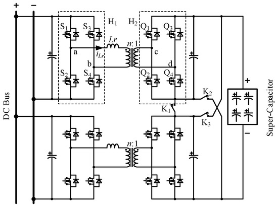
Figure 2.
Topology diagram of a CM-2L-DAB converter.
Therefore, assuming a DC bus voltage V1 and super-capacitor voltage V2 ∈ V2,min, V2,max and power is equally shared between two modules, the operation of the CM-2L-DAB is classified into two modes.
where CM-2L-DAB is in IPOS.
where CM-2L-DAB is in IPOP.
HV mode: V2 ∈ [(V2,min + V2,max)/2, V2,max]
LV mode: V2 ∈ [V2,min, (V2,min + V2,max)/2]
2.2. Modulation Scheme
Due to the topology reconfiguration, the output voltage range of each 2L-DAB is essentially [V2,min/2, V2,max/2]. However, even with a reduced voltage range, the conventional single-phase-shift (SPS) modulation is still insufficient for a high efficiency operation of the CM-2L-DAB due to loss of soft-switching in the light-load condition. Therefore, to adapt to the output voltage range, each DAB module employs the extended-phase-shift (EPS) modulation [27].
The operation waveform of the EPS is shown in Figure 3. All switches operate with a 50% duty cycle over a switching period Ts. When V1 > nV2, the phase shift between S1 and S4 define the inner phase shift ratio D1 ∈ [0, 0.5], and the phase shift between S1 and Q1 define the outer phase shift ratio D2 ∈ [0, 0.5]. Depending on the relationship of D1 and D2, two modulation modes are derived for the EPS, where D1 ≤ D2 as shown in Figure 3a accounts for the heavy-load mode, and D2 < D1 as shown in Figure 3b accounts for the light-load mode.
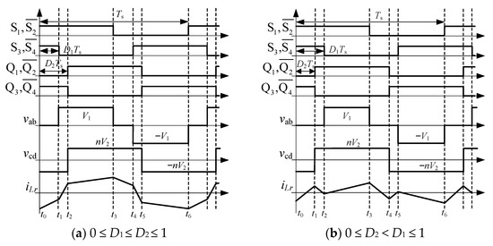
Figure 3.
Operation waveform of the EPS modulation.
The transferred power of the 2L-DAB module can be expressed as
Assuming a base power transfer of PN = nU1U2/8fsLr, the per-unit transferred power of the 2L-DAB with the EPS modulation is
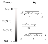
To reduce the conduction loss across the wide voltage range, a minimum RMS current method is applied to the EPS, resulting in optimal phase shift ratios as listed in Table 1, where k = nV2/V1. It should be noticed that with the EPS modulation, all switches can realize zero-voltage switching (ZVS) in the full operating range.

Table 1.
Phase shift ratio of CM-2L-DAB.
3. Topology and Modulation of 3L-DAB
3.1. Topology Description
Compared to the conventional 2L-DAB converter, the 3L-DAB converter replaces an H-bridge with a 3L-NPC full bridge on the side of the super-capacitor, as shown in Figure 4. Therefore, it consists of 12 switches, 16 diodes, 1 HF transformer, and three DC-link capacitors in total. The 3L full bridge can generate 3 voltage levels, i.e., 0, ±V2/2, and ±V2, which provide a higher DoF than a 2L-bridge.
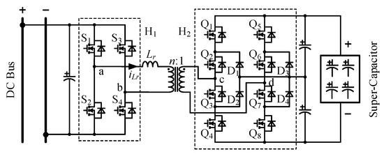
Figure 4.
Topology diagram of a 3L-DAB converter.
3.2. Modulation Scheme
To facilitate a wide voltage range, a hybrid modulation method is proposed for the 3L-DAB, which fully uses the additional voltage level of ±V2/2. The proposed method is also divided into the HV mode and LV mode, which uses the output voltage V2,bd as the boundary of two modes.
The operation waveform of the LV mode is shown in Figure 5a, where the primary side AC voltage vab is a 50% square wave and the secondary side AC voltage vcd is an asymmetric 4-level square wave. In this mode, one DoF of the modulation is the interval of the voltage level ±V2 equaling mTs, respectively, where m ∈ [0, 0.5]. Moreover, the outer phase shift ratio D2 ∈ [−0.5, 0.5] is also employed as the other DoF to control the direction and magnitude of the power flow.
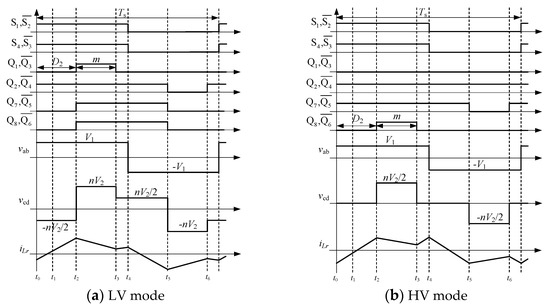
Figure 5.
Operation waveforms of the hybrid modulation method for the 3L-DAB.
As the output voltage increases, the value of m in the LV mode decreases and finally reaches zero following the voltage-second matching principle, which naturally transits to the HV mode with only ±V2/2 and 0 voltage levels for vcd, as shown in Figure 5b. In the HV mode, the interval of the voltage level ±V2/2, i.e., mTs, and the outer phase shift ratio D2 are employed as two DoFs of the modulation. The value of m in the HV mode naturally decreases with an increasing output voltage.
The power transfer of the 3L-DAB depends on the relationship between m and D2. Defining −0.5 ≤ D2 < −m as Mode M1, −m ≤ D2 < 0 as Mode M1, 0 ≤ D2 < 0.5 − m as Mode M3, and 0.5 − m ≤ D2 ≤ 0.5 as Mode M4, the per-unit transferred power of the LV mode is expressed as
And the per-unit transferred power of the HV mode is
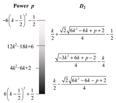
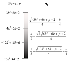
From (3) and (4), the phase shift ratio of the proposed hybrid modulation method is obtained, and the results are listed in Table 2. It should be noticed that the switches, except Q2 and Q3, can realize ZVS in all operation conditions.

Table 2.
Phase shift ratio of 3L-DAB.
From the perspective of the operation principle, it is clear that both the CM-2L-DAB and the 3L-DAB have an HV mode and an LV mode for a wide voltage range operation. The key difference is the mode transition of the CM-2L-DAB is realized by the operation of relays, which need to power off the converter temporarily. The mode transition of the 3L-DAB is realized by modulation schemes, which are fast and continuous.
4. Converter Design and Loss Modeling
In order to provide an effective comparison, the converter design and loss modeling procedures are presented in this section as a preliminary step. Moreover, for obtaining a fair comparison, it is assumed that the switching frequency, input and output voltage ranges, and the maximum magnetic density and winding wire diameter of the transformer are identical for the CM-2L-DAB and the 3L-DAB. In this design example, the rated power is set as 200 kW. The input voltage is 750 V, and the output voltage on the super-capacitor side is 300–1500 V.
4.1. Converter Design
4.1.1. Transformer
Higher switching frequency is beneficial for reducing the volume of passive elements, but it will increase the loss of the transformer core, causing heat accumulation. Moreover, a higher magnetic flux density of the transformer results in a smaller core loss, but it corresponds to more winding turns, leading to a larger winding loss. Therefore, the design of transformers should be carefully designed according to the multiple objectives.
- Leakage inductance: in order to reduce the converter size and avoid the auxiliary inductance, Lr is expected to be contributed to by the leakage inductance of the transformer. Its value is constrained by the transmission power. Define the output voltage corresponding to the rated power of 200 kW as V2′. Since the CM-2L-DAB is equally shared by the two separate DAB converters, the rated power for each is P′ = 100 kW. The leakage inductance is
- Core design: in order to reduce the volume and loss of the core, the U-shaped tape-wound core of nanocrystalline material with high saturation magnetic density and low coercivity is selected. The Area Product (AP) method can be employed to select the core parameters, in which the area product Ap is the product of the core winding window area Aw and cross-sectional area Ae, i.e,where Po represents the maximum output power, η is the transformer efficiency, Ks is the lamination coefficient of the strip winding core, Kf is the waveform coefficient, Ku is the core window utilization coefficient, and Jrms is the winding current density. fs is the switching frequency, and Bm is the maximum magnetic density. Note that Jrms, fs, and Bm should be selected with the tradeoff between volume and power loss. Here, as a rule of thumb, η is set as 0.99, and Ks = 0.75, Kf = 4, Ku = 0.4, Jrms = 400 A/cm2, and fs = 15 kHz are set as the initial values. If the power loss is unacceptable, they should be adjusted.
- Winding design: in order to avoid the surge of loss caused by the skin effect and proximity effect under high-frequency operation, the shaped copper litz wire was selected as the winding wire, and the radius of each strand was controlled within the skin depth. The skin depth of copper at 100 °C can be calculated as
The winding diameter is the ratio of the maximum RMS current to the current density. As mentioned, the current density is set as Jrms = 400 A/cm2. According to Figure 5, the maximum RMS current can be derived and thereby the winding diameter is
The next step is to determine the number of windings turns, which is determined as
where Um is the maximum RMS voltage of winding. Basically, the smaller number of windings turns corresponds to less impact of the skin effect. But since it is limited by the window shape, N may also need to be iteratively adjusted.
Based on the above analysis, the transformer design flowchart is depicted in Figure 6. Following the design flow, the transformer parameters for the two types of converters are listed in Table 3.
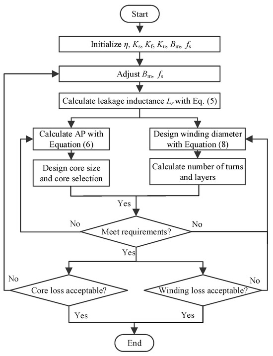
Figure 6.
Flowchart of transformer design.

Table 3.
Parameters of transformers.
4.1.2. Semiconductor Devices
The semiconductor devices include SiC MOSFETs, and Si diodes are selected based on the withstand voltage and current. Securing sufficient margin, the SiC MOSFET selected for the 2L-DAB is AIMZHN120R010M1T, and five SiC MOSFETs are connected in parallel as a switch. As for the 3L-DAB, AIMZHN120R010M1T SiC MOSFETs are also selected for S1~S4, Q1 and Q4, Q6 and Q7, and Q5 and Q8. The numbers of paralleled MOSFETs for them are 5, 10, 12, and 10, respectively; while Q2 and Q3 use IMBG65R007M2H SiC MOSFETs with 10 parallel connections; D1 and D2 and D3 and D4 use IDWD140E120D7 Si diodes with 12 and 10 parallel connections, respectively. The characteristics of the selected MOSFETs and diodes are presented in Table 4.

Table 4.
Parameters of semiconductor devices.
4.1.3. Filter Capacitors
The value of the filter capacitor to smooth the output voltage is determined as
where ΔVC is the peak–peak voltage ripple, iC is the capacitor current, iHo is the dc-side current of the H bridge, and iR is the load current.
Suppose ΔVC is 1% of the rated voltage and ensure sufficient margin. The filter capacitance is designed as 4.3 mF for the 2L-DAB; as for the 3L-DAB, the capacitance in the H1 bridge is 3.3 mF, and the capacitance in the H2 bridge is 8.8 mF. Considering that the voltage on the capacitor is high and the capacitance is large, the paralleled film capacitor with high withstand voltage is chosen.
4.2. Loss Modeling
The loss in the DAB converter mainly includes the following four parts: core loss and winding loss of the transformer and the conduction loss and switching loss of the semiconductor devices. The mathematical models of them are derived as follows.
4.2.1. Transformer Core Loss
The improved generalized Steinmetz equation (iGSE) can be used to calculate the transformer core loss [28]. The iGSE for DAB is
where tn and Bn are the segmentation instant and the magnetic flux density, respectively, and the expressions of ki and ΔB are
4.2.2. Transformer Winding Loss
The winding loss of the transformer can be calculated as
where Rw is the AC resistance of the winding.
Due to the high frequency effect, the AC resistance is often several times the DC resistance. The ratio of AC resistance RwAC to DC resistance RwDC can be approximated with Dowell’s equation which is [29]
where
Therein, Nl is the number of winding layer, kl is the number of litz wire strands in a single turn, dl is the diameter of a single bare wire, δw is the skin depth, and η is laminar factor.
The DC resistance RwDC can be obtained as
where ρw is the wire resistivity, N is the number of winding turns, and lT is the average turn length of the winding, which can be estimated at 1.2 times the circumference of the magnetic column.
Combining (15)~(18), the winding loss of the transformer can be obtained.
4.2.3. Conduction Loss of the Semiconductor Devices
The conduction loss of the MOSFETs is expressed as
where RDSon is the on-resistance of MOSFET, Nsw_pl is the number of the paralleled MOSFETs, and Isw_rms is the current flowing through the switching position.
Different with the MOSFET, the on-resistance of power diodes cannot be found in the datasheet, because its conduction characteristics are not linear due to conductance modulation effects. Therefore, the linear fitting method is employed here, defining VD0 as the diode starting voltage and the forward voltage drop as vD; fitting the slope as the on-resistance rD, the conduction loss of the diode can be deduced as
4.2.4. Switching Loss of the Semiconductor Devices
The turn-on and turn-off losses of the MOS transistor are expressed as
Notice that the turn-on and turn-off process of MOSTET is a symmetrical process of charging and discharging the parasitic capacitor. Taking the turning-off instant as an example, Voff and Ioff are the corresponding voltage and current before turning off, respectively, and the tvr and tif represent the period of voltage rise and current drop, respectively, expressed as
where RG is driving resistance, Crss and Ciss are the feedback capacitor and input capacitor, respectively, and Vth and Vgp are the threshold voltage and Miller plateau voltage, respectively. They can be obtained from the datasheet.
The switching loss of the diode mainly includes two parts: (1) the switching-off loss of the clamping diode, and (2) the reverse recovery loss of the diode connected in parallel with the MOS transistor, which occurs when the other MOS transistor in the same bridge arm is hard switching. Define VRR, IRRM, trr, and Qrr as reverse recovery voltage, maximum current, time, and charge, respectively, and considering tb = trr, the switching loss of the diode can be obtained as
And the recovery loss of the paralleled diode is determined by the reverse recovery charge Qrr, i.e,
5. Performance Comparison of Topologies
In this section, the performance of the two previously designed converters will be compared in the six major domains, which are modulation strategy, soft-switching characteristic, current stress, power loss, material usage, and reliability. To cover different output voltages and power conditions, six operation points are selected which are a. V2 = 500 V, P = 50 kW (low voltage and light load), b. V2 = 500 V, P = 200 kW (low voltage and full load), c. V2 = 900 V, P = 50kW (average voltage and light load), d. V2 = 900 V, P = 200 kW (average voltage and full load), e. V2 = 1300 V, P = 50 kW (high voltage and light load), and f. V2 = 1300 V, P = 200 kW (high voltage and full load).
5.1. Comparison of Modulation Strategy
The EPS modulation of the CM-2L-DAB and the hybrid modulation of the 3L-DAB are validated via PLECS circuit simulation at the six operation points. The operation waveforms are shown in Figure 7. It is validated in Figure 7a that the CM-2L-DAB operates in the IPOP configuration and the EPS modulation with D2 < D1, while the 3L-DAB operates in the HV mode with 4 voltage levels. In Figure 7b, the CM-2L-DAB operates in the same LV mode but using other EPS modulation with D1 < D2, while the outer phase shift ratio D2 of the 3L-DAB increases with the load. In Figure 7c,d, when V2 increases to 900V, the CM-2L-DAB operates in the IPOS configuration and the EPS modulation, while the 3L-DAB operates in the HV mode with only two voltage levels. In Figure 7e,f, when V2 further increases to 1300 V, the CM-2L-DAB remains in the IPOS configuration, but the inner phase shift ratio D1 decreases, while the 3L-DAB remains in the HV mode but with a smaller m. The operation waveforms validate the effectiveness of the modulation strategies for both topologies.
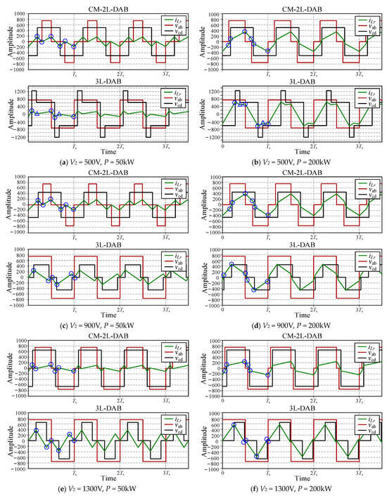
Figure 7.
Modulation strategy comparison of CM-2L-DAB and 3L-DAB (〇 for soft-switching and △ for hard switching).
5.2. Comparison of Soft-Switching Characteristic
The soft-switching condition of switches in 3L-DAB is determined by the instantaneous inductor current at each switching moment, which is listed in Table 5, where the per-unit value iN = nV2/(4fsLr). According to the employed voltage-second matching principle, m = k − 0.5 in the LV mode, while m = k in the HV mode. The polarity of the switching currents in different modes is further derived. As shown in Table 5, the switching currents marked in green are always positive, the switching currents marked in red are always negative, and the switching currents in yellow can be either positive or negative.

Table 5.
Instantaneous inductor current of 3L-DAB in p.u.
According to the operation waveforms of the 3L-DAB in Figure 5, the ZVS conditions of all switches are listed in Table 6. After checking the instantaneous inductor current in Table 4, all of the switches realize ZVS except for Q2 and Q3 in M1, M3, and M4 of the LV mode. Moreover, S1–S4 realize Zero-Current Switching (ZCS) in M3 of the HV mode.

Table 6.
ZVS conditions of the 3L-DAB.
The ZVS condition of the CM-2L-DAB is given in Table 7. It is proved that with the proposed EPS modulation, all switches can realize ZVS in the CM-2L-DAB converter.

Table 7.
ZVS conditions of the CM-2L-DAB.
The switching conditions of all switches in both topologies are marked in the operation waveforms in Figure 7 and summarized in Table 8. It confirms that all switches of the CM-2L-DAB realize soft-switching under all operation conditions, whereas switches Q2 and Q3 of the 3L-DAB are hard switched in the low-voltage condition. It is also interesting to notice that despite two switches not always being soft switched in the 3L-DAB, switches Q1 to Q4 are normally on or off for the medium-to-high-voltage condition, which do not have any switching action.

Table 8.
Comparison of soft-switching characteristics.
5.3. Comparison of Current Stress
The transformer peak current of the 3L-DAB with the SPS modulation and the proposed hybrid modulation (HM) is firstly compared in Figure 8a. It is evident that the proposed hybrid modulation significantly reduces the current stress of the 3L-DAB at all voltage and load levels. A further comparison is made between the peak current of the CM-2L-DAB with the EPS and the 3L-DAB with the hybrid modulation in Figure 8b. It should be noted that peak current of the CM-2L-DAB represents only one DAB module. It is clear that the CM-2L-DAB has a lower transformer peak current than the 3L-DAB at most of the operation points.
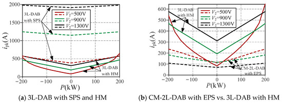
Figure 8.
Current stress comparison.
5.4. Comparison of Power Loss
The power losses of two topologies are evaluated and compared using the loss models derived in Section 4. A bidirectional load range of [−200 kW, 200 kW] is scanned for three output voltage levels {500 V, 900 V, 1300 V}. The power loss breakdown is shown in Figure 9. Compared to the 3L-DAB, the CM-2L-DAB has a lower total power loss in nearly all conditions. The largest difference is shown under the low-voltage condition of V2 = 500 V, where the IPOP configuration halves the device current stress of the CM-2L-DAB leading to a significantly lower device conduction loss and transformer winding loss. For the 3L-DAB, the high current at the low output voltage flows through the 3L-NPC bridge where switches are connected in series, leading to even higher conduction loss. In the low-to-medium-voltage condition, the conduction loss and winding loss are dominated at the heavy load for both topologies. It should also be noticed that the power loss of the CM-2L-DAB is symmetrically distributed under bidirectional load conditions, but for the 3L-DAB the power loss of the forward transmission is higher than the reverse mode under the low-voltage condition. This is due to the fact that the voltage waveforms and transferred power of the LV mode for the 3L-DAB are asymmetric regarding the bidirectional power.
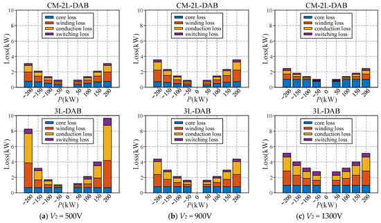
Figure 9.
Comparison of power loss breakdown.
The resulting conversion efficiency of the CM-2L-DAB and the 3L-DAB are compared in Figure 10. The peak efficiency of the CM-2L-DAB is 98.81% at V2=1300 V and P = ±190 kW, whereas the lowest efficiency is 95.92% at V2 = 1300 V and P = ±50 kW. The peak efficiency of the 3L-DAB is 98.37% at V2 = 500 V and P= −90 kW, whereas the lowest efficiency is 89.67% at V2 = 1300 V and P = ±50 kW. It is shown that both converters can achieve a peak efficiency higher than 98%, but the light load efficiency of the CM-2L-DAB is much higher than the 3L-DAB.

Figure 10.
Efficiency comparison.
5.5. Comparison of Material Usage
The material usage of the CM-2L-DAB and the 3L-DAB is compared using the design results of Section 4. The comparison includes both semiconductor devices and passive components, which is summarized in Table 9. It is shown that the CM-2L-DAB uses nearly doubled magnetic core and winding material than the 3L-DAB and 36% less semiconductor devices. Due to the requirement of the split capacitor for the 3L-NPC bridge, the 3L-DAB has a 21% larger capacitor rating than the CM-2L-DAB. Moreover, the CM-2L-DAB requires three additional power relays for the topology reconfiguration.

Table 9.
Converter material usage.
5.6. Closed-Loop Control Scheme
As shown in Figure 11, in the CM-2L-DAB, each submodule employs a closed-loop output power regulator with a reference to the equally shared power. It should be noticed that a feedforward control parameter calculation can be implemented based on the analytical solution of the EPS modulation. On top of the submodule-level control, a system-level mode selection module is implemented based on the output voltage to control the power relays.
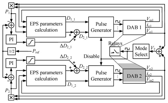
Figure 11.
Closed-loop control diagram of the CM-2L-DAB converter.
As shown in Figure 12, the output power control of the 3L-DAB is implemented with a proportional-integral (PI) regulator with feedforward parameter calculation. The hybrid modulation mode is selected based on the output voltage and another PI regulator is used to balance the DC-link capacitor voltages.
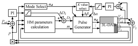
Figure 12.
Closed-loop control diagram of the 3L-DAB converter.
By comparing the closed-loop control scheme of the CM-2L-DAB and 3L-DAB converters, it is found that both topologies can use feedforward parameter calculation to improve the transient performance, and they both use a closed-loop regulator to balance the DC-link capacitor voltages. However, an essential difference is that the CM-2L-DAB requires distributed control hardware architecture, while the 3L-DAB only needs a single control unit.
5.7. Reliability
Reliability is another important domain to compare two topologies, which involves many aspects such as semiconductor devices, passive components, a cooling system, and converter control and operation. This section will not cover all these factors but only point out the key differences and concerns between the CM-2L-DAB and the 3L-DAB.
For the 3L-DAB, the switching characteristic of switches in 3L-NPC bridges is different as shown in Table 8, which will lead to unequal power loss distribution and a deviated aging speed of devices. This may affect the reliability of the 3L-DAB converter.
For the CM-2L-DAB, the major reliability concern is the usage of power relays. When the converter operates in a wide voltage range, the power relays need to be frequently switched. This increases risks of failure that will significantly decrease the reliability of the CM-2L-DAB converter. Therefore, from the perspective of reliability, the topology of the CM-2L-DAB converter should not be frequently reconfigured.
6. Conclusions and Outlook
This paper compares the CM-2L-DAB and the 3L-DAB converters for super-capacitor charging applications. To tackle the challenge of the wide voltage range, the EPS modulation in conjunction with the topology reconfiguration is analyzed for the CM-2L-DAB, while a hybrid modulation method is proposed for the 3L-DAB. Moreover, a unified design approach is proposed for two topologies, which also provides power loss models. A comprehensive comparison of two topologies yields the following conclusions:
- (1)
- The CM-2L-DAB can realize soft-switching of all switches over a wide voltage range, while two switches of the 3L-DAB cannot realize soft-switching in low-voltage conditions;
- (2)
- The CM-2L-DAB is more efficient than the 3L-DAB in most operation points, since it employs semiconductor devices more effectively, i.e., series connection for high voltage and parallel connection for high current. Thus, the current stress of the CM-2L-DAB is considerably lower;
- (3)
- The CM-2L-DAB uses 36% less semiconductor devices and 21% smaller capacitors than the 3L-DAB, but the usage of the magnetic material is nearly doubled, and three power relays are necessary;
- (4)
- The CM-2L-DAB has a more critical reliability concern than the 3L-DAB due to the additional power relays;
- (5)
- The CM-2L-DAB needs to be powered off when the power relays are reconfigured, which decreases the dynamic performance.
To summarize, a trade-off can be made based on the voltage characteristic of the load profile: (1) When the load voltage does not switch back and forth between the high-voltage and low-voltage ranges/modes very frequently, the CM-2L-DAB converter is a preferred topology, since it offers a higher efficiency, and the reliability and dynamics are acceptable. (2) However, when the load voltage frequently and dynamically changes between the high-voltage and low-voltage ranges/modes, the 3L-DAB converter would outperform, since it allows smooth and online mode transition.
Potential advancements of the CM-2L-DAB converter can be realized by replacing the power relays with bidirectional solid-state switches, especially the emerging monolithic bidirectional switches, which allow for fast topology reconfiguration with improved reliability and dynamic performance. However, it should be noted that no matter which bidirectional solid-state switch topology is employed, an IGBT with at least another diode is in the conduction loop, resulting in higher power loss. This may offset the inherent advantage of the CM-2L-DAB in efficiency. Advanced modulation schemes using both phase-shift angles and duty cycles can further reduce the power loss of the CM-2L-DAB and 3L-DAB converter, and intelligence algorithm such as pareto-optimization and artificial neural networks can be employed in the parameter design to yield an optimal trade-off between the efficiency, power density, reliability, and costs. Moreover, with advances in the performance of the wide band-gap devices, SiC MOSFETs and IGBTs with higher voltage and current rating can be used in bidirectional DC–DC converters to further simply the topology and improve the efficiency.
Author Contributions
Conceptualization, Y.H. and W.X.; methodology, Y.H.; software, M.S.; validation, M.S.; formal analysis, Y.H.; investigation, C.Z.; resources, R.L.; data curation, M.S.; writing—original draft preparation, Y.H.; writing—review and editing, R.L.; visualization, M.S.; supervision, C.Z.; project administration, W.X.; funding acquisition, W.X. All authors have read and agreed to the published version of the manuscript.
Funding
This research was funded by the Science and Technology Project of the State Grid Jiangsu Electric Power Company, grant number J2023043.
Data Availability Statement
The original contributions presented in the study are included in the article, further inquiries can be directed to the corresponding author.
Conflicts of Interest
Authors Wenqiang Xie, Mingming Shi, Chenyu Zhang, and Ruihuang Liu were employed by the State Grid Electric Power Research Institute of Jiangsu Province, and Author Yuying He was employed by the Hohai University. The remaining authors declare that the research was conducted in the absence of any commercial or financial relationships that could be construed as a potential conflict of interest.
References
- Tracking Trends in a Time of Change: The Need for Radical Action towards Sustainable Transport Decarbonisation, Transport and Climate Change Global Status Report—2nd Edition. Available online: www.tcc-gsr.com (accessed on 21 August 2024).
- Aviation and Shipping, IEA, Paris. Available online: https://www.iea.org/reports/aviation-and-shipping (accessed on 21 August 2024).
- Sulligoi, G.; Bosich, D.; Pelaschiar, R.; Lipardi, G.; Tosato, F. Shore-to-ship power. Proc. IEEE 2015, 103, 2381–2400. [Google Scholar] [CrossRef]
- Karimi, S.; Zadeh, M.; Suul, J.A. Shore charging for plug-in battery-powered ships: Power system architecture, infrastructure, and control. IEEE Electrif. Mag. 2020, 8, 47–61. [Google Scholar] [CrossRef]
- Stana, G.; Voitkans, J.; Kroics, K. Supercapacitor constant-current and constant-power charging and discharging comparison under equal boundary conditions for dc microgrid application. Energies 2023, 16, 4167. [Google Scholar] [CrossRef]
- Raveendhra, D.; Poojitha, R.; Narasimharaju, B.L.; Dreglea, A.; Liu, F.; Panasetsky, D.; Pathak, M.; Sidorov, D. Part-I: State-of-the-art technologies of solar powered dc microgrid with hybrid energy storage systems-architecture topologies. Energies 2023, 16, 923. [Google Scholar] [CrossRef]
- Jung, J.-H.; Kim, H.-S.; Ryu, M.-H.; Baek, J.-W. Design methodology of bidirectional CLLC resonant converter for high-frequency isolation of dc distribution systems. IEEE Trans. Power Electron. 2013, 28, 1741–1755. [Google Scholar] [CrossRef]
- Min, J.; Ordonez, M. Bidirectional resonant CLLC charger for wide battery voltage range: Asymmetric parameters methodology. IEEE Trans. Power Electron. 2021, 36, 6662–6673. [Google Scholar] [CrossRef]
- De Doncker, R.W.A.A.; Divan, D.M.; Kheraluwala, M.H. A three-phase soft-switched high-power-density DC/DC converter for high-power applications. IEEE Trans. Ind. Appl. 1991, 27, 63–73. [Google Scholar] [CrossRef]
- Kheraluwala, M.N.; Gascoigne, R.W.; Divan, D.M.; Baumann, E.D. Performance characterization of a high-power dual active bridge DC-to-DC converter. IEEE Trans. Ind. Appl. 1992, 28, 1294–1301. [Google Scholar] [CrossRef]
- Van Hoek, H.; Neubert, M.; De Doncker, R.W. Enhanced modulation strategy for a three-phase dual active bridge—Boosting efficiency of an electric vehicle converter. IEEE Trans. Power Electron. 2013, 28, 5499–5507. [Google Scholar] [CrossRef]
- Wei, Y.; Luo, Q.; Mantooth, H.A. LLC and CLLC resonant converters based DC transformers (DCXs): Characteristics, issues, and solutions. CPSS Trans. Power Electron. Appl. 2021, 6, 332–348. [Google Scholar] [CrossRef]
- Mukherjee, S.; Kumar, A.; Chakraborty, S. Comparison of DAB and LLC DC–DC converters in high-step-down fixed-conversion-ratio (DCX) applications. IEEE Trans. Power Electron. 2021, 36, 4383–4398. [Google Scholar] [CrossRef]
- Zumel, P.; Ortega, L.; Lázaro, A.; Fernández, C.; Barrado, A.; Rodríguez, A.; Hernando, M.M. Modular dual-active bridge converter architecture. IEEE Trans. Ind. Appl. 2016, 52, 2444–2455. [Google Scholar] [CrossRef]
- Krismer, F.; Kolar, J.W. Efficiency-optimized high-current dual active bridge converter for automotive applications. IEEE Trans. Ind. Electron. 2012, 59, 2745–2760. [Google Scholar] [CrossRef]
- Hou, N.; Li, Y.W. Overview and comparison of modulation and control strategies for a non-resonant single-phase dual-active-bridge dc–dc converter. IEEE Trans. Power Electron. 2020, 35, 3148–3172. [Google Scholar] [CrossRef]
- Huang, J.; Wang, Y.; Li, Z.; Lei, W. Unified triple-phase-shift control to minimize current stress and achieve full soft-switching of isolated bidirectional dc–dc converter. IEEE Trans. Ind. Electron. 2016, 63, 4169–4179. [Google Scholar] [CrossRef]
- Hu, J.; Cui, S.; De Doncker, R.W. Natural boundary transition and inherent dynamic control of a hybrid-mode-modulated dual-active-bridge converter. IEEE Trans. Power Electron. 2022, 37, 3865–3877. [Google Scholar] [CrossRef]
- Moonem, M.A.; Krishnaswami, H. Control and configuration of three-level dual-active bridge DC-DC converter as a front-end interface for photovoltaic system. In Proceedings of the 2014 IEEE Applied Power Electronics Conference and Exposition-APEC 2014, Fort Worth, TX, USA, 16–20 March 2014. [Google Scholar]
- Filba-Martinez, A.; Busquets-Monge, S.; Nicolas-Apruzzese, J.; Bordonau, J. Operating principle and performance optimization of a three-level NPC dual-active-bridge dc–dc converter. IEEE Trans. Ind. Electron. 2016, 63, 678–690. [Google Scholar] [CrossRef]
- Liu, P.; Chen, C.; Duan, S.; Zhu, W. Dual phase-shifted modulation strategy for the three-level dual active bridge dc–dc converter. IEEE Trans. Ind. Electron. 2017, 64, 7819–7830. [Google Scholar] [CrossRef]
- Filba-Martinez, A.; Busquets-Monge, S.; Bordonau, J. Modulation and capacitor voltage balancing control of multilevel NPC dual active bridge dc–dc converters. IEEE Trans. Ind. Electron. 2020, 67, 2499–2510. [Google Scholar] [CrossRef]
- Song, B.; Sangwongwanich, A.; Yang, Y.; Pan, Y.; Blaabjerg, F. Analysis and optimal modulation for 2/3-level DAB converters to minimize current stress with five-level control. IEEE Trans. Power Electron. 2023, 38, 4596–4612. [Google Scholar] [CrossRef]
- Wu, J.; Wang, T.; Shu, Z.; Ma, L.; Wang, S.; Nie, J. Power balance control based on sensorless parameters estimation for ISOP three-level DAB converter. IEEE Trans. Ind. Electron. 2024, 71, 12414–12424. [Google Scholar] [CrossRef]
- Wu, X.; Zhang, Y.; Yang, J. Neutral-point voltage balancing method for three-phase three-level dual-active-bridge converters. Energies 2022, 15, 6463. [Google Scholar] [CrossRef]
- He, J.; Chen, Y.; Lin, J.; Chen, J.; Cheng, L. Wang. Review of modeling, modulation, and control strategies for the dual-active-bridge dc/dc converter. Energies 2023, 16, 6646. [Google Scholar] [CrossRef]
- Li, X.; Zhang, X.; Lin, F.; Sun, C.; Mao, K. Artificial-intelligence-based hybrid extended phase shift modulation for the dual active bridge converter with full ZVS range and optimal efficiency. IEEE J. Emerg. Sel. Top. Power Electron. 2023, 11, 5569–5581. [Google Scholar] [CrossRef]
- Vazquez, N.; Liserre, M. Peak current control and feed-forward compensation for the DAB converter. In Proceedings of the 2019 IEEE International Conference on Industrial Technology (ICIT), Melbourne, VIC, Australia, 13–15 February 2019; pp. 685–690. [Google Scholar]
- Hu, J.; Yang, Z.; Cui, S.; De Doncker, R.W. Closed-form asymmetrical duty-cycle control to extend the soft-switching range of three-phase dual-active bridge converters. IEEE Trans. Power Electron. 2021, 36, 9609–9622. [Google Scholar] [CrossRef]
Disclaimer/Publisher’s Note: The statements, opinions and data contained in all publications are solely those of the individual author(s) and contributor(s) and not of MDPI and/or the editor(s). MDPI and/or the editor(s) disclaim responsibility for any injury to people or property resulting from any ideas, methods, instructions or products referred to in the content. |
© 2024 by the authors. Licensee MDPI, Basel, Switzerland. This article is an open access article distributed under the terms and conditions of the Creative Commons Attribution (CC BY) license (https://creativecommons.org/licenses/by/4.0/).
