Abstract
This paper addresses the problem of the geothermal energy generation process in a depleted gas reservoir with a specific enhanced geothermal system, applying CO2 as an energy transporting medium. Constructed models of the system components are used to perform coupled and dynamic simulation forecasts, taking into account the interdependence of the individual system elements operating in a cyclical fluid flow and the continuous changes in temperature, pressure, and the composition of circulating fluids. The simulation procedure of the geothermal energy generation process is applied to the realistic example of a depleted gas reservoir located in Foresudetic Monocline, Poland. The simulation results are presented in detail and discussed with several conclusions of both case-specific and general characters. Three phases of the energy recovery process can be distinguished, varying in the produced fluid composition and the evolution of the fluid temperature. These phases result in the corresponding behavior of the produced stream power: increasing, stable, and decreasing for the three phases, respectively. Other significant results of the simulation forecasts are also discussed and concluded. In general, the complexity of the obtained results proves the necessity to apply the system’s detailed modeling and simulations to reliably plan and realize a geothermal energy generation project.
1. Introduction
Geothermal energy is thermal energy in the Earth’s crust that is transferred from the hot core and mantle of the planet. The primal source of this heat is half the processes of radioactive decay of radioactive elements and half the original energy created during the formation of the planet. The stream of geothermal energy is estimated at 44.2 TW and the resources are large enough to maintain this stream for many billions of years. Although the stream of geothermal energy is a negligible fraction of the energy stream that arrives on the Earth from the Sun, it exceeds the current demand for energy in the global economy by more than twice. Due to the relatively small carbon footprint left when extracting geothermal energy, it is treated as “green” and renewable. Currently, 13.9 GW of geothermal energy power are being extracted globally (2019) [1] in industrial processes and 28 GW [2] are used in direct district heating systems. Standard technologies for obtaining geothermal energy include:
- -
- hot springs,
- -
- deep aquifers with temperatures above 100 °C,
- -
- deep, “dry” rock formations requiring the stimulation of the transport parameters and external water sources as a heat-exchanging medium (so-called enhanced geothermal systems–EGS).
In recent years, research studies and investment projects on the recovery of geothermal energy from depleted oil reservoirs [3,4,5,6,7] and natural gas reservoirs [8,9,10,11,12,13,14] have also been initiated. The initial estimate of the energy potential of depleted domestic hydrocarbon reservoirs as sources of geothermal energy is over 400 TJ for individual locations [15]. For typical geological conditions with a geothermal gradient of approx. 30 °C/km, such reservoirs must be located at a depth of over 3000 m. As a consequence, their transport and storage parameters are significantly reduced. Although the standard carrier of geothermal energy is water, which has the advantages of a high heat capacity and excellent thermal stability, in the conditions of deep hydrocarbon reservoirs with limited permeability, its mobility is low, which significantly reduces the injectivity of wells used for water injection into the reservoir and increases its flow resistance in the porous structures. Therefore, in such cases, the advantage of using CO2 as a fluid transferring geothermal energy over H2O according to [16] include:
- -
- a lower viscosity, resulting in larger flow velocities for a given pressure gradient,
- -
- a larger expansivity, resulting in larger density differences between cold CO2 in the injecting wells and warm CO2 in the producing wells, and consequent smaller energy losses in the fluid circulation system.
Therefore, supercritical CO2 has much greater mobility compared with water, which more than compensates for its lower heat capacity [17]. This is one of the main reasons for the use of CO2 in standard geothermal sources within EGS systems [18]. The methods of acquiring geothermal energy from depleted hydrocarbon reservoirs with the use of supercritical CO2 are in the early stages of development. In particular, this applies to domestic conditions, where the geothermal phase is treated as one of three stages of exploitation of these structures [15,19].
Most of the published studies concerning the extraction of geothermal energy included numerical simulations of particular systems. Pruess [20] investigated the significance of producing well completion specifications for its performance. Zhang et al. [21] analyzed standard EGS systems and compared the thermodynamic performance of CO2-based vs. H2O-based systems. Pan et al. [22] analyzed the optimum CO2 flow rate required to generate a positive electric power output. Pan and Oldenburg [23] investigated variations in the supercritical CO2 properties and thermal–hydraulic turbulence features to CO2 in a standard doublet CO2–EGS system. Hongwu Lei [24] analyzed a classical five-spot model performance, including net heat extraction, flow rate, and production temperature applying both H2O-based and CO2-based EGS.
This work aimed to carry out simulation forecasts of the complete geothermal energy generation process, covering all the elements of the system designed for the implementation of this process. The system included a realistic, depleted hydrocarbon reservoir, existing producing and injecting wells, and surface installation elements, including pipelines, separators, and heat exchangers. Simulations were carried out for a selected, domestic gas field. It should be emphasized that the simulations are coupled and dynamic, taking into account the interdependence of the individual system elements operating in a cyclical fluid flow system transporting geothermal energy from the reservoir through producing wells, surface installation, and injecting wells back into the reservoir, taking into account continuous changes in temperature, pressure, and the composition of circulating fluids. The system of geothermal energy recovery from a hydrocarbon reservoir consists of several elements, presented schematically in Figure 1 and described below, where the capital letters A, B, …, and H5 refer to the elements presented in the figure.
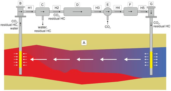
Figure 1.
Diagram of a system for geothermal energy recovery from a hydrocarbon reservoir using CO2. The arrows indicate flow direction.
A—reservoir—where the thermal energy is transferred from the rock mass and original fluids to the fluid (mainly CO2), transporting energy to the surface,
B—producing well—where losses of both hydrodynamic and thermal energies are observed,
C—separator—allows for the separation of the contaminated, possibly liquid, phases of the fluid (brine) from its CO2 component and possible residual hydrocarbon gas, where CO2 is the basic carrier of geothermal energy,
D—heat exchanger installation—in which the transfer of thermal energy from the conveying fluid to the usable energy system takes place,
E—manifold—allows for the replenishment of the stream of the transporting fluid with external CO2 to compensate for the components separated out of the produced fluid; the manifold is placed before the next component of the system (F), i.e., a compressor, to facilitate the preparation of the injected gas,
F—compressor—provides hydrodynamic energy to the fluid to be injected into the reservoir with the required efficiency,
G—injecting well—where variations in the injecting fluid pressure and temperature take place,
H1, …, H5—connecting pipelines—where losses of both hydrodynamic and thermal energies are observed.
It should be noted that the producing well in the diagram may, in general, refer to a system of several producing wells working in parallel. Similarly, an injecting well in the diagram denotes, in general, a possible system of several parallel injecting wells. It should be also noted that a decrease in the temperature of the flowing media is observed within all the elements in the diagram, except the reservoir and the possible exception of the compressor. This decrease consists of a deliberate and controlled component within the heat exchanger and an unavoidable and disadvantageous component within other elements as the loss of geothermal energy of the transporting fluid. Similarly, in these elements, except for the compressor, there is a decrease in the pressure of the transporting fluid, which is a manifestation of the loss of hydrodynamic energy of this fluid. For the quantitative description of the variation in temperature, pressure, and other parameters (fluid mass rates and compositions) of the energy-transporting fluid, the corresponding values at the inlet and outlet of each element are correlated according to their numerical models described below and referring to the diagram in Figure 1.
2. Geological Settings
The area of interest of our study geographically focuses on the middle part of the Warsaw–Berlin ice-marginal valley, along the river valleys of the Warta and Prosna. It is encircled by the Krotoszyn Plateau from the south, the Gniezno Plateau from the north, the Kalisz–Turek Plateau from the east, and its western margin is the moraine hills of the Leszczyńska Plateau. Geologically, the selected gas field is a depleted gas reservoir located in the Western part of the Foresudetic Monocline. Natural gas was tectonic-structurally trapped within the Saxonian subgroup of the Rotliegend sandstone formation. The Rotliegend sandstones were developed as thick-bedded, high-porosity, dune-shaped aeolian sandstones with a low clay content. The axis of the gas reservoir structure is elongated in the NW–SE direction. The caprock of the reservoir is lithologically diverse, but it is mostly composed of the Zechstein impermeable anhydrides and salts of the Werra and Strassfurt cyclothems. Above the Zechstein interval, the sub-Cenzoic complex of the Malmian age is characterized by variable tectonics, thickness, varying degrees of diagenesis, and changes caused by karst and other secondary geological processes. The gas reservoir is sealed from the SW direction by the fault zone striking NW–SE. The reservoir layers, separated by interdune surfaces, during its tectonic development, were tiled and inclined toward the NE direction. The gas reservoir structure is elongated along the NE–SE axis, where three local highs attached to the sealing fault may be observed in Figure 2.
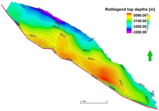
Figure 2.
Structural map of the top of the Rotliegend formation for the selected gas field after [25]. The red line represents the intersection of the main sealing fault with the top surface of the Rotliegend formation.
In general, the Rotliegend sandstones represent good reservoir rock, characterized by a considerable average thickness, high average porosity, and intermediate permeability. The gas-bearing zone has the highest thickness adjacent to the fault zone and pinches out to gas–water contact toward the NE direction. Reservoir sandstones pronounce a high horizontal isotropy of transport properties but with a poorer quality of the topmost layer.
3. Geological Model
The 3D geological model of the selected gas field was constructed in [15]. The structural model of the selected gas field and the surrounding area was developed based on a structural map of the top of the Rotliegend formation [25] presented in Figure 2 and a map of the thickness of the Rotliegend sandstones. The bottom layer map of the reservoir model was reconstructed using well log data. The geometry and thickness maps of the inner horizons of the reservoir model were mapped based on stratigraphic markers determined in borehole profiles. Finally, the reservoir interval of the Rotliegend sandstones was subdivided into nine layers. The orientation of the simulation grid was consistent with the main axes of the structure. The horizontal dimensions of the 3D grid blocks varied from 200 m to 400 m, with an average of 250 m along the main axes (NW–SE), and varied from 40 m to 260 m, with an average value of 130 m, for the perpendicular direction. The total thickness of the reservoir varied, across the entire model, between 36 m and 126 m, with an average value of 75 m. The inner layers’ thicknesses ranged individually between 0.5 and 21 m, and averaged to 8 m. Additionally, the wellbore area of all the wells had a higher resolution with the applied radial type of local grid refinement (LGR). The geologic model was finally characterized by 7220 active blocks in total. The created structural model of the reservoir was parametrized with the spatial distribution of transport properties, including porosity, permeability, and the thickness net-to-gross (NTG) ratio that are summarized in Table 1.

Table 1.
Basic reservoir properties of the reservoir model.
The spatial distributions of the NTG, total porosity, effective porosity, and permeability were calculated and calibrated [15] based on the well log interpretations and lab results from core samples and developed by applying the Gaussian random function simulation algorithm with the co-kriging and variogram options included. The total porosity values varied from 1.4% to 28.6%, with an average value of 17%, but the effective porosity ranged from 0% to 28%, with an average value of 15.5%. The detailed distribution of the porosity parameter is shown in Figure 3.
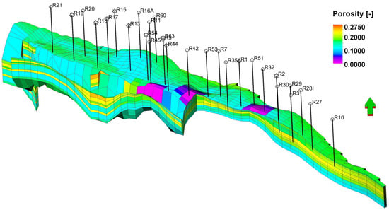
Figure 3.
3D grid of the reservoir simulation model with the distribution of the porosity in the selected gas field after [15]. The southwest part of the model is cut out to display the internal structure of the gas-bearing zone.
The absolute horizontal permeability model was determined by finding a firm relationship between the core lab porosity and the measured permeability (adjustment coefficient, R2 = 0.8096). The most representative relationship is presented in Figure 4, based on data from the well R-2-calibrated to well-test results.
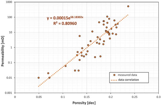
Figure 4.
The relationship between the core lab porosity and the measured permeability. Orange points are the most representative dataset from well R-2.
The permeability was directly calculated from the previously developed porosity distribution. The absolute horizontal permeability amounts up to 195 mD, with an average value of 32 mD. In this model, the vertical absolute permeability was initially reduced by the order of magnitude to indicate the layered nature of the reservoir rock.
4. Dynamic Model
The dynamic modeling process was completed by supplementing the developed geological model with the three required components: initial equilibrium distribution of the reservoir fluids (gas, brine), relative permeabilities of the reservoir fluids (transport properties), and the thermodynamic model of the reservoir fluid (gas).
Originally, the reservoir simulation model included the presence of two reservoir fluids (brine, hydrocarbon gas). For the geothermal energy recovery, the fluids were supplemented with CO2. The initial gas–water contact was estimated at the depth of 3132.5 m b.s.l. The distribution of the initial water saturation was introduced using the J-Leverett function, as shown below:
where and k denote the porosity and permeability, respectively, and and are the contact angle and the interfacial tension at the gas–water interface, respectively.
The water saturation profiles were matched for every well based on the interpreted petrophysical well logs. A satisfactory match, with a model deviation from the well saturation logs of about 4–5%, was obtained using a four-parameter J-function model, presented below:
where , represents the connate water saturation, and the coefficients in Equation (2) were found to be: = 0.0094, = 0.0657, = 2, = 10, and = 0.035.
The Rotliegend sandstone was considered a standard viscous flow rock, characterized by phase permeability and the equilibrium thermodynamic variables of reservoir pressure and temperature. The transport characteristics were described by the relative permeabilities of reservoir fluids. The power model of relative permeabilities was applied, due to the lack of direct measurements of the Rotliegend reservoir rock. The relative permeability of water () and gas () as functions of the reduced saturation of water () and gas (), respectively, were calculated using the following relationships:
where , = 1, and the irreducible water saturation .
where , , , and the residual gas saturation .
A reservoir simulation model was developed as a compositional model with a thermodynamic model of the reservoir fluid (gas) based on the Soave–Redlich–Kwong (SRK) equation of state (EOS) using the PVTSim ver. 13.1 software by Calsep, Copenhagen, Denmark. The original fluid model of the selected gas field was built for non-liquid nitrogen-rich natural gas and included five components (C1, C2, C3, N2, CO2) with associated parameters calculated for the initial conditions (Pinit = 35.2 MPa, Tinit = 385 °K), presented below in Table 2 and Table 3. For viscosity, correlation of the Pedersen model was applied.

Table 2.
EOS parameters of the reservoir fluid model for the Soave–Redlich–Kwong (SRK) model.

Table 3.
Fluid model binary coefficients for the Soave–Redlich–Kwong (SRK) EOS model.
The thermodynamic parameters of brine with the density, rw = 1219.5 kg/m3, were established as follows: formation volume factor, Bw = 1.045 m3/sm3, and isothermal compressibility, cw = 5.3 × 10⁻⁵ 1/bar. The viscosity of brine was = 0.31, and the coefficient of viscosity change with pressure was = 6.0 × 10⁻⁵ 1/bar under the initial pressure and temperature conditions, Pinit, Tinit.
Due to the observed activity of formation waters, two numerical aquifers, partially surrounding the selected gas field from the north, were implemented. For both, the Carter–Tracy infinite aquifer model was applied.
5. Geothermal Model
The geothermal model was developed by implementing the required thermal parameters into the dynamic model. These thermal parameters included the initial distribution of the reservoir temperature, the thermal conductivity coefficient of the reservoir rock, the relationship between the specific heat of the reservoir fluids and the temperature, and the relationship between the reservoir fluids’ viscosity and temperature.
The initial reservoir temperature was distributed across the entire model by implementing a relationship assuming an increase in temperature with depth. That relationship was established based on temperature logs recorded at the Rotliegend intervals of eight boreholes.
The value of the heat conductivity coefficient of the Rotliegend sandstones (155 kJ/m·day·°C) was estimated according to [26], for the initial temperature of 115 °C. The relationship between the specific heat capacity, Cs, of the reservoir fluids and the temperature, T, was approximated using a straightforward equation by Sommerton [27]:
for the temperature range of 50–115 °C, expected in the analyzed geothermal system. In this range, the specific heat capacity increased exponentially with temperature from 825 to 940 kJ/(rm3·°C). The relationship between the reservoir fluid viscosities and the temperature was adopted after the website [28]. For the same range of temperatures, the viscosity of CO2 slightly decreased from 0.1 to 0.07 cP.
Cs(T) = 0.452·T0.155
6. History Matching
The simulation model of the selected gas field was matched against the production data and calibrated to obtain data compliance. The production data of 35 producing wells covered 30 years of historic reservoir activity. The production history control data included the daily and monthly production rates of gas and water, and also the pseudostatic bottom-hole pressures. Additionally, the production data were used to calculate the water-to-gas ratios to verify the two-phase flows within the reservoir. The history matching process involved applying the following steps: ensuring the actual production of reservoir fluids (gas and water) from individual wells, the reproduction of bottom-hole pressure variations, the restoration of the water-to-gas ratio, correction of the bottom-hole pressures to fit the measured values, and the verification of the final values of the water-to-gas ratio.
Proper reproduction of the evolution of the bottom-hole pressures and the values of the water-to-gas ratio required the modification of several parameters of the simulation model. Modifications of the simulation model covered the global model parameters, the separated region parameters, and the near-wellbore zone parameters. The following parameters were taken into account during the calibration procedure:
- -
- aquifer property modifications, including the thickness, haqu, effective compressibility, caqu, permeability, kaqu, porosity, ϕaqu, and reservoir–aquifer contact radius, raqu,
- -
- effective porosity,
- -
- absolute permeability,
- -
- partial barriers with reduced transmissibility to effectively isolate parts of the reservoir,
- -
- near-wellbore zone modifications, including the transport properties of the LGR regions around producing wells,
- -
- relative water permeability parameters: maximum water permeability, , and irreducible water saturation, ,
- -
- relative gas permeability parameters: maximum gas permeability, , and residual gas saturation, .
The quality of the data match was satisfactory. The pressure match was characterized by the general fitting error of 2–5 bar. An average reservoir pressure drop of about 160 bar was noted, from 352 bar to 194 bar, from 1992 to 2007. In the next 15 years, the average reservoir pressure decreased to 71 bar. To obtain this pressure match, the partial local barriers were introduced in the central part of the reservoir to properly reproduce the hydrodynamic communication between the producing wells. Modifications of the transport properties within implemented LGR regions contributed to correctly reproducing the water-to-gas ratios in the producing wells. The observed increasing average reservoir water-to-gas ratio from 3.0 × 10⁻⁶ sm3/sm3 (in 1992), through 5.0 × 10⁻⁵ sm3/sm3 (in 2007), up to about 1.0 × 10⁻⁴ sm3/sm3 (in 2022), indicated an upward trend of formation water activity. The pore volume occupied by water increased by 0.8 × 10⁶ rm3, through the production history of the reservoir. The total water influx from the aquifer into the reservoir of 5.2 × 10⁶ sm3 was observed at the end of the production period. An example of the calibration procedure for the selected well of R-54 in terms of the bottom-hole pressures, gas production rates, and cumulative gas production is shown in Figure 5. Another example of the calibration procedure in terms of the water-to-gas ratio for the well R-18 is given in Figure 6.
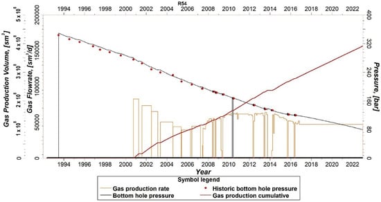
Figure 5.
An example of the reservoir model calibration for a selected well. Measurements vs. simulation results of bottom-hole pressures, gas production rates, and gas cumulative production.
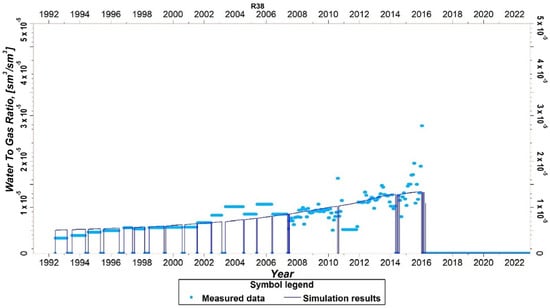
Figure 6.
An example of the reservoir model calibration for a selected well. Measurements vs. simulation results of the water-to-gas ratio.
7. Variability of Fluid Flow and Composition in System Components
The conditions of continuity of the fluid stream and its mass components determine particular relationships between:
- -
- reservoir outflow denoted by the subscript (“res,out”) and separator inflow (“sep,in”) quantities: for mass rates Qsep,in = Qres,out, for CO2 contents cCO2,sep,in = cCO2,res,out, for residual hydrocarbon contents cCH,sep,in = cCH,res,out, and for water contents cH2O,sep,in = cH2O,res,out,
- -
- separator outflow (“sep,out”) and manifold inflow (“m,in”) quantities: for mass rates Qm,in = Qsep,out, for CO2 contents cCO2,m,in = cCO2,sep,out, and for residual hydrocarbon contents cCH,m,in = cCH,sep,out,
- -
- manifold outflow (“m,out”) and reservoir inflow (“res,in”) quantities: for mass rates Qres,in = Qm,out, for CO2 contents cCO2,res,in = cCO2,m,out, and for residual hydrocarbon contents cCH,res,in = cCH,m,out,
- -
- in the separator, there is a change in the mass rate of the stream (from Qsep,into Qsep,out) and its composition (from cCO2,sep,in, cCH,sep,in, cH2O,sep,in to cCO2,sep,out, cCH,sep,out), as described in more detail below,
- -
- in the manifold, there is a change in the mass rate (from Qm,in to Qm,out) and its composition (from cCO2,m,in, cCH,m,in, na cCO2,m,out, cCH,m,out), as described in more detail below.
To ensure the maximum possible stability of the reservoir conditions, the volumetric rate of the injected fluids (CO2 and residual hydrocarbons) under reservoir temperature and pressure conditions, qRres,in, is maintained at a level identical to the volumetric rate of the produced fluids, qRres,out, (CO2, residual hydrocarbons, and brine) under reservoir temperature and pressure conditions:
qRres,out = qRres,in
The respective mass rates, i.e., Qres,out and Qres,in, are fundamentally different due to the different compositions of these fluids (cCO2,res,out, cCH,res,out, cH2O,res,out vs. cCO2,res,in, cCH,res,in, cH2O,res,in = 0) and the different temperatures (Tres,out, Tres,in) and pressures (Pres,out, P res,in) at the inflow/outflow to/from the reservoir:
where the functions, fres,Q,out and fres,Q,in, result from the standard thermodynamic PVT correlations for the produced and injected fluids.
Qres,out = fres,Q,out(qRres,out, Tres,out, Pres,out, cCO2,res,out, cCH,res,out, cH2O,res,out)
Qres,in = fres,Q,in(qRres,in, Tres,in, Pres,in, cCO2,res,in, cCH,res,in)
The change in the flow rate and composition of the fluid at the outflow of the separator (Qsep,out, cCO2,sep,out, cCH,sep,out) about its inflow (Qsep,in, cCO2,sep,in, cCH,sep,in, cH2O,sep,in) is a function of the separation conditions and is calculated using the model:
Qsep,out − Qsep,in = fsep,Q(Tsep,in, Psep,in, cCO2,sep,in, cCH,sep,in, cH2O,sep,in, …)
cCH,sep,out − cCH,sep,in = fsep,CH(Tsep,in, Psep,in, cCO2,sep,in, cCH,sep,in, cH2O,sep,in, …)
cCO2,sep,out − cCO2,sep,in = 0
cH2O,sep,out = 0
The functions, fsep,Q and fsep,CH, result from the fluid components’ continuity conditions. The last element for which there is a change in the rate and composition of the fluid is the manifold where the rate at the outflow, Qm,out, is increased about the rate at the inflow, Qm,in, by the rate of CO2 from an external source, QCO2,ext, compensating for the reduction in the rate of the produced fluid in the separator:
QCO2,ext = Qres,out − Qres,in = Qm,out − Qm,in
Accordingly, the composition of the fluid at the outflow of the manifold is changed according to the following dependencies:
Qm,out × cCO2,m,out = Qm,in. × cCO2,m,in + QCO2,ext
Qm,out × cCH,m,out = Qm,in. × cCH,m,in
8. Pressure Variability in System Components
In all the system components, except for the compressor and the injecting well, there is a pressure drop at their outflow, Pα,out, cf. the pressure at the inflow, Pα,in, determined by the properties of a given element described by the model, fα,P(Qα,in, cβ,α,in, …), given by:
where α is an element of the system, α = {res, prod, sep, ex, m, pipe}, and β is a component of the fluid, β = {CO2, CH, H2O}.
Pα,in − Pα,out = fα,P(Qα,in, cβ,α,in, …) > 0
In the compressor and the injecting well, denoted with a subscript α = “c” and “inj”, and described by the model fα,P(Qα,in, cβ,α,in, …), there is an increase in pressure:
Pα,out − Pα,in = fα,P(Qα,in, cβ,α,in, …) > 0
The functions fα,P are determined in Section 10 and Section 11 below.
9. Temperature Variability in System Components
In all the system components, except for the reservoir and possibly the compressor, there is a drop in temperature at their outflow, Tα,out, cf. their inflow temperature, Tα,in, determined by the properties of a given element described by the model, fα,T(Qα,in, cβ,α,in, …), given by:
where α is an element of the system, α = {prod, sep, ex, m, inj, pipe}, and β is a component of the fluid, β = {CO2, CH, H2O}.
Tα,in − Tα,out = fα,T(Qα,in, cβ,α,in, …) > 0
In the reservoir and possibly in the compressor, denoted by the subscript, α = res and c, described by the models, fres,T(Qres,in, cβ,res,in, …) and fc,T(Qc,in, cβ,c,in, …), respectively, there is an increase in temperature, given by:
Tres,out − Tres,in = fres,T(Qres,in, cβ,res,in, …) > 0
Tc,out − Tc,in = fc,T(Qc,in, cβ,c,in, …) > 0
To sum up, hydrodynamic and thermal models of the individual system elements were used to determine the above dependencies, in particular:
- -
- the model of the reservoir (geothermal structure),
- -
- well models,
- -
- the surface installation model.
It should be noted that the system of equations applied to describe the analyzed system of geothermal energy recovery requires a self-coupled solution corresponding to the closed loop of the flow of the fluid transporting geothermal energy. This means that, for example, finding temperature variability in the system elements comes down to making the temperature of the fluid produced from the reservoir, Tres,out, dependent on the temperature of the fluid injected into the reservoir, Tres,in, through the modeling of the reservoir phenomena, where, in turn, the temperature of the injected fluid, Tres,in, is a function of the temperature of the produced fluid, Tres,out, by modeling the flow of this fluid through the wells and the surface installation. In practice, this means performing iterative calculations of the above relationships until the results are consistent.
10. Correlations of Temperature and Pressure in Producing and Injecting Wells
According to the heat exchange model presented in [29], the temperature calculation procedure in the case of the producing wells concerns the situation when the mixture of brine, hydrocarbons (crude oil, natural gas), plus CO2 flows out of the producing wells. All the calculations were carried out assuming the supercritical conditions of temperature and pressure.
The following stages can be distinguished in the calculation procedure:
- -
- determining the velocity of the fluid flow in the well,
- -
- determining the density of CO2 and the other fluid components as a function of average temperature and pressure,
- -
- calculation of the average density of the fluids (using the average density of the mixture components according to their concentration in the mixture),
- -
- determination of the mixture viscosity under the supercritical conditions of temperature and pressure [30],
- -
- calculation of the mass flow rate of the multi-component mixture,
- -
- calculation of the Reynolds number of the flowing fluid,
- -
- calculation of the specific heat of the analyzed mixture,
- -
- calculation of the average thermal conductivity coefficient of the mixture under the supercritical conditions of the temperature based on the volume fraction of each component of the mixture [31],
- -
- calculation of the Prandl number of the flowing fluid,
- -
- calculation of the heat transfer coefficient between the flowing fluid and the surrounding rocks,
- -
- determining the value of the [m] coefficient, defined by the following formula [29]:
—cross-section of the wellbore [m2],
—flow velocity of the fluid [m/s],
—average specific heat of the fluid [J/(kg × K)],
—average density of the fluid [kg/m3],
—effective thermal connectivity of the well [W/(m × K)],
Hence, the coefficient depends on the Reynolds (21) and Prandtl (22) numbers:
where:
—characteristic length (wellbore diameter) [m],
—fluid viscosity [cP].
The effective thermal conductivity of the well depends on the internal diameter of the well, the thermal conductivity coefficient of the casing pipe and its external and internal diameters, as well as the thermal conductivity coefficient of the cement rock.
The equation that was used for the calculation of the temperature depth profile in the producing well (following [29,32,33]) is given below:
where:
—temperature of the produced fluid as a function of depth [°C],
B—coefficient is given in equation no. (19),
—reservoir temperature [°C],
—total depth of the wellbore [m],
—depth [m],
—geothermal gradient [°C/m].
The equation for the temperature vs. the depth in an injecting well follows:
where:
—temperature of the injected CO2 as a function of depth [°C],
—CO2 temperature at the wellhead [°C].
A separate issue is to calculate the pressure that is required to maintain the desired flow rate for the production and the injecting well. Assuming the bottom-hole pressure and flow rate are known, we can calculate the wellhead pressure according to the general relation:
wellhead pressure = bottom-hole pressure − flow resistance (pressure drop) − hydrostatic pressure
The equations used to calculate the pressure drop consist of two components corresponding to the flow resistance and the hydrostatic column. The former given in (26) is commonly used in the oil and gas industry and proposed by [34]. The numerical values in this formula result from its conversion to the SI system:
where:
—flow resistance (pressure drop) [MPa],
—total depth of the wellbore [m],
—fluid density [kg/m3],
Q—fluid flow rate [m3/min],
—fluid viscosity [cp],
—internal diameter of tubing pipes [m].
The formula of the hydrostatic component is given in (27):
where:
—hydrostatic pressure [MPa],
—fluid density [kg/m3],
—acceleration due to gravity [m/s2],
—depth [m].
To assess the efficiency of the geothermal well, the wellhead pressure that corresponds to the known bottom-hole pressure must be determined, taking into account the pressure drop in the wellbore intervals with different diameters. It should also be noted that variations of mixture parameters along the wellbore cause the change in the Reynolds number, Prandl number, and thus the heat transfer coefficient. Hence, the changes in the mixture parameters influence the value of the mixture temperature at the wellhead.
Other factors that influence the temperature of the fluid flowing out of the producing well are:
- -
- the degree of thermal insulation that depends on the thermal conductivity of the casing pipes and the cement rock. These factors depend on the well construction details, including various casing diameters and steel grades,
- -
- the quality of the cement job (for example, resulting in a deficiency in cement behind the casing), which affects the amount of heat transfer between the reservoir rocks and the flowing fluid,
- -
- the borehole diameter, varying along the borehole depth due to varying drilling bit diameters and the possible creation of cavities around the borehole,
- -
- the depth profile of the rock temperature around the borehole; it is typically assumed that there is a constant surface temperature and geothermal gradient,
- -
- in the procedure applied in this study, it is assumed that:
- the producing wells’ bottom-hole temperature and pressure are known as a result of the reservoir simulations and are used to calculate the temperature and pressure at the producing wellheads,
- for the injecting wells, the bottom-hole pressures are known from the reservoir simulations, where they result from the assumed injection rates, and the wellhead temperatures are known from the temperature profile along the surface installation. Hence, the wellhead pressures and bottom-hole temperature of the injected fluid are determined from the injecting well correlations between the wellhead and bottom-hole quantities.
11. Correlations of Temperature and Pressure in Surface Installation
The components of the surface installation affecting the amount of useful energy recovery are:
- -
- the injection and producing wellheads,
- -
- the water separator,
- -
- the heat exchanger,
- -
- the manifold for CO2 replenishment in the system,
- -
- the pipelines connecting the other installation components.
In addition to the physical properties of the installation itself, the amount of useful energy recovered is also influenced by the flow rate of the reservoir mixture, and the physical parameters of the circulating fluid: pressure, temperature, and chemical composition.
The energy balance on the gain side includes the heat energy transferred from the energy-carrying fluid to the mains water in the heat exchanger, and on the loss side:
- -
- the heat lost to the surroundings in the pipelines of the installation, injection, and producing wellheads, and the separator,
- -
- the hydrodynamical energy losses associated with overcoming the flow resistance in the individual components of the installation, as listed in the above point,
- -
- the loss of other forms of energy associated with the need to raise the pressure to a value that allows the injection fluid (CO2 and possible residual hydrocarbons) to be injected into the reservoir by injecting the wellbores, and with the need to replenish the stream of the transporting fluid with external CO2 to compensate for the water separated out of the produced fluid.
With an assumed length of installation pipelines >200 m and a reservoir geothermal heat energy >500 kW, the main components of the installation associated with energy loss to the surroundings are the installation pipelines. The other components of the installation produce relatively small amounts of energy losses.
Wellhead fluid for depleted oil and gas fields can contain three components: CO2, H2O, and oil or gas–the third component is marked with an ‘X’. Pre-insulated pipes with an average insulation thickness of approximately 40 mm (for pipeline inside diameters of up to 150 mm) were chosen to connect the system components. In the adopted variant for the extraction of heat from the geothermal reservoir, it was assumed that each cluster has one central heat exchanger to which the pipelines from the individual producing and injecting wells are shown in Figure 7. The following designations were adopted: n—index to describe the heat exchange on the installation before the exchanger, k—index to describe the heat exchange on the installation behind the exchanger. It was assumed that the temperature of CO2 at the injecting wellhead was .

Figure 7.
Diagram for calculating the heat output of the heat exchanger and heat losses in the system pipes. n—index to describe the heat exchange on the installation before the heat exchanger, k—index to describe the heat exchange on the installation behind the heat exchanger. Source: own work.
The thermal power of the heat exchanger [W] can be calculated according to the formula:
where:
—weighted average specific heat of the mixture (CO2 + X) at a constant pressure for all k-th sections of the installation at the inflow of the heat exchanger [J/(kg·K)],
—fluid temperature at the inflow of the heat exchanger, [°C],
—fluid temperature at the outflow of the heat exchanger, [°C],
—mass flow rate of the mixture (CO2 + X) in the i-th section of the installation at the outflow of the heat exchanger, [kg/s].
The average mass flow rate to each of the injecting wellheads is assumed as:
where:
—mass flow rate of the mixture (CO2 + X) from the i-th section of the installation to the inflow of the heat exchanger, [kg/s],
—number of installation sections between the outflow of the heat exchanger and the injecting wellheads, [-].
The temperature [°C] was calculated according to the formula:
where:
—specific heat of the mixture flowing from the i-th section of the installation (producing wellhead) to the inflow of the heat exchanger, [J/(kg·K)],
—temperature of the mixture in the i-th producing wellhead, [°C],
—heat loss to the surroundings at the i-th section of the installation to the inflow of the heat exchanger, [W].
The heat loss was calculated according to the formula:
where:
—function for the heat loss to the surroundings per meter of pipeline length as a function of the pipeline diameter and the fluid temperature from the producing wellhead for the i-th section of the installation to the heat exchanger, [W/m],
—length of the i-th section of pipeline to the heat exchanger, [m].
The temperature drop, [°C], along the i-th section of the installation between the heat exchanger and the injecting wellhead:
where:
—fluid temperature at the outflow of the heat exchanger (assumed 50 °C), [°C],
—fluid temperature at the i-th injecting wellhead, [°C].
The temperature drop is given by the formula:
where:
—heat loss to the surroundings along the i-th section pipeline from the heat exchanger to the i-th injecting wellhead, [W],
—weighted average specific heat of the mixture at a constant pressure for all the i-th sections pipeline from the heat exchanger to the i-th injecting wellhead, [J/(kg·K)],
—mass flow rate of the mixture in the i-th sections pipeline from the heat exchanger to the i-th injecting wellhead, [kg/s].
The heat loss, , was calculated according to the formula:
where:
—function for the heat loss to the surroundings per meter of the pipeline length as a function of the pipeline diameter and the fluid temperature at the inflow of the i-th section of the installation from the heat exchanger to the injecting wellhead, [W/m],
—length of the i-th pipeline section from the heat exchanger to the injecting wellhead, [m].
The specific heat of the mixture in the i-th pipeline section to the heat exchanger can be calculated using formula:
where:
—mass flow rate of CO2 in the i-th pipeline section of the installation to the heat exchanger, [kg/s],
—mass flow rate of X in the i-th pipeline section of the installation to the heat exchanger, [kg/s],
—specific heat of CO2 at a constant pressure, [J/(kg·K)],
—specific heat of ‘X’ at a constant pressure, [J/(kg·K)].
The specific heat at a constant pressure for a mixture in all the pipeline sections from the heat exchanger to the injecting wellheads, calculated using the formula:
where:
—mass flow rate of CO2 in the i-th pipeline section of the installation from the heat exchanger to the injecting wellhead, [kg/s],
—mass flow rate of X in the i-th pipeline section of the installation from the heat exchanger to the injecting wellhead, [kg/s].
For the calculation of the energy losses associated with overcoming the flow resistance in the individual components of the installation, the following permissible pressure drops were assumed: 0.5 bar in the production and injecting wellheads, 1.0 bar in the heat exchanger, 1.0 bar in the separator, and 1.0 bar in the pipelines.
The Darcy–Weisbach equation applies to the selection of pipeline diameters describing the fluid pressure drop, [Pa], caused by the dissipation of mechanical energy in the pipeline. The following form of this equation was used:
where:
—inner pipe diameter, [m],
—permissible pressure drop for a given pipe length , [Pa],
—friction factor, [-],
—pipe length, [m],
—density of the fluid, [kg/m3],
—fluid velocity, [m/s].
For the turbulent flow, the friction factor, , can be determined according to the Walden formula [35], which, in addition to the Reynolds number, takes into account the absolute roughness of the pipe, [m]:
where
Reynolds number :
—dynamic fluid viscosity, [Pa·s],
—absolute roughness of the pipe, [m].
The value of = 0.005 m was assumed, taking into account the corrosive nature of the reservoir mixture, as the typical corrosion rate for contaminated CO2 is 0.01 mm/year [36] and the geothermal reservoir lifetime is typically 50 years. The diameter of the pipeline must not be too large to avoid excessive pipeline costs, and it must not be too small as this causes excessive fluid velocities, excessive pressure losses, and accelerates corrosion.
In determining the density and viscosity of CO2 for the dense phase, a relationship can be used that gives these values as a polynomial function of pressure and temperature [37]. The density and viscosity of the reservoir brine for different pressures and temperatures can be read from graphs [38]. The density and viscosity of a gas consisting mainly of methane and nitrogen can be determined using an online calculator [39].
It should be noted that a complete energy balance of the analyzed system of geothermal energy recovery should include other forms of energy, in particular, external energy required to:
- -
- replenish the stream of the transporting fluid with external CO2 to compensate for the brine separated out of the produced fluid,
- -
- compress the fluid (CO2) to be injected into the reservoir with the required efficiency.
12. Simulation Results of Geothermal Energy Recovery and Discussion
Before the commencement of the proper geothermal energy recovery project, the selected gas field was restored to its original temperature and pressure conditions by the injection of the appropriate quantities of CO2. That stage of the project lasted 9 years and was formally completed at the end of 2031. The process of obtaining geothermal energy from the field was carried out independently for six groups of wells, hereinafter referred to as clusters with the symbols G-NN, G-N, G-CN, G-C, G-CS, and G-S. The locations of these clusters, together with the injecting and producing wells, are shown in Figure 8.
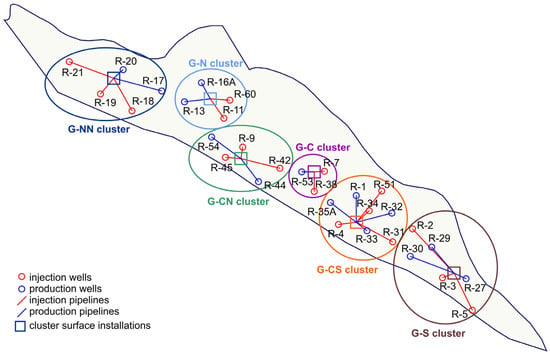
Figure 8.
Map of the selected gas field with the locations of the individual wells and their clusters.
A detailed list of the producing and injecting wells assigned to each cluster is given in Table 4.

Table 4.
List of the producing and injecting wells in the clusters of the selected gas field.
Within each cluster, the producing and injecting wells were selected to maximize the areas covered by the injected CO2 in the geothermal energy recovery process. In addition to the producing and injecting wells, each cluster included a surface installation consisting of pipelines (shown in Figure 8) connecting the wellheads to the other components of the installation, including the separators and heat exchangers.
The simulation forecast of the proper geothermal energy recovery phase of the project started at the beginning of 2032 and was completed at the end of 2081. The combined simulation results for all six of the above clusters (G-NN, G-N, G-CN, G-C, G-CS, G-S) and the 14 producing wells implementing the project of geothermal energy recovery from the selected gas field are presented in Figure 9 and Figure 10. Figure 9 shows the temperature evolution of the produced fluids at the bottom of the producing wells as one of the primary factors determining the amount of geothermal energy that can be recovered. By the end of the simulated 50-year period, it indicates a decrease in this temperature by a relatively small amount (below 3 °C) for all the clusters, except for the wells of the G-CS cluster.
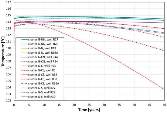
Figure 9.
Evolution of the bottom-hole temperatures for the individual producing wells of all the clusters.
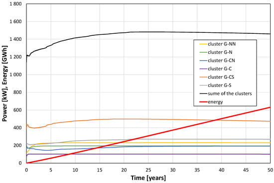
Figure 10.
Geothermal power and energy are obtained from exchangers for all the clusters of the selected gas field.
Figure 10 presents the essential simulation results of the geothermal energy recovery project in terms of power and total energy obtained up to 50 years of the project duration. This power varies from 1.14 MW at the beginning of the project through a maximum value of 1.48 MW reached after approximately 21 years to a value of 1.46 MW at the end of the project, while its average value is 1.44 MW. The total energy recovered in the period of 50 years amounts to 631 GWh.
The variations of the results shown in Figure 10 for different clusters are caused by various factors, mainly by:
- -
- different numbers of producing and injecting wells–the largest cluster G-CS consists of four producing and four injecting wells vs. the smallest cluster, G-C, of one producing and two injecting wells,
- -
- different nominal producing and injecting rates for individual wells corresponding to their historical performance.
The above factors also determined the rate of temperature decrease observed in the bottom-hole temperatures of fluids produced by different wells, as presented in Figure 9.
The simulation of the geothermal recovery process delivers other detailed results that are useful to analyze its significant characteristics. The total reservoir volume where the geothermal process takes place was found to be 615.0 Mm3. The largest contribution of 82% to this volume comes from the reservoir rock. The other contributions come from reservoir fluids and are equal to 10.2%, 6.4%, and 1.4% for brine, CO2, and residual hydrocarbon gas, respectively. The average temperatures and pressures of the four above components vary during the geothermal recovery process and their initial and final values according to the simulation results are given in Table 5.

Table 5.
Basic parameters of the geothermal system components.
Under the reservoir pressure and temperature conditions, the significant component properties of density, r, and specific enthalpy, h, are also included in Table 5. Those properties were adopted after the website [28] (CO2 and residual hydrocarbon gas), with the correlations from [40] (brine), and with [33,41,42] (sandstone rock). The total quantities required to estimate the geothermal energy characteristics of the system are given in Table 6, which includes the total volumes, V, masses, M, and enthalpies, H, of all the system components at the initial (subscript “ini”) and final (subscript “fin”) states of the geothermal recovery process under thermal equilibrium among the components.

Table 6.
Basic characteristics of the geothermal system components.
Despite the relatively small value of the specific enthalpy, the total enthalpy of the reservoir rock dominates over the other components of the system due to its huge volume and mass contribution, and its enthalpy reduction results from the decrease in the reservoir temperature. The total enthalpy of the in-place brine is reduced due to both the temperature reduction and the decreasing brine quantity. An analogous comment refers to the residual hydrocarbon gas. Contrary to the above three components, the total enthalpy of CO2 in the reservoir increases despite its relatively large temperature reduction. This is solely caused by the effective increase in the CO2 amount as injected to replace the reservoir brine and hydrocarbon gas.
The final results of the available geothermal energy in terms of in-place enthalpy reduction, ΔH, are shown in Table 7.

Table 7.
Enthalpy variation of the geothermal system components.
The distribution of effective enthalpy production (defined as the enthalpy of the fluids at the bottom holes of the producing wells minus the enthalpy of the fluids at the bottom holes of the injecting wells) among the fluids (shown in Table 8) differs from the distribution of the in-place enthalpy reduction, ΔH, in Table 7. Contrary to the latter, the former distribution indicates CO2 as the dominating (almost a 70% contribution to the total quantity) carrier of the recovered geothermal energy, thus confirming the effectiveness of this fluid as a medium transporting geothermal energy from the depleted gas reservoir to the surface installation.

Table 8.
Effective reservoir enthalpy production by various fluids.
The distribution of the effective enthalpy production among all the six clusters of the geothermal energy recovery system, applied in the analyzed project, shown in Table 9, is quite non-uniform. While the effective enthalpy produced by CO2 is approximately proportional to the size of a cluster (in terms of the number of wells–see Table 4), as evident in the cases of clusters G-CS and G-S vs. cluster G-C, the effective enthalpies produced by the residual hydrocarbon gas and, in particular, by brine are not correlated with the cluster sizes but are rather specific to the cluster locations.

Table 9.
Effective enthalpy production in clusters by various fluids.
The non-uniformity of the above distributions is significantly reduced when the enthalpy is expressed in terms of this quantity per a single well of each cluster, as shown in Figure 11.
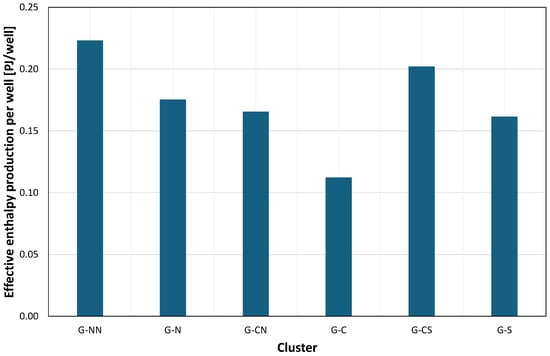
Figure 11.
Effective enthalpy production per well.
However, this result may suggest a possible improvement in the geothermal energy recovery system by a redistribution of both the wells among the clusters and the total production and injection stream distributions among the wells in each cluster. It should be noted that the practical optimization procedure for the geothermal energy recovery system would require including financial factors—a task to be performed in another study under preparation.
Other significant results of interest concern the variations of fluid power along the sequential elements of the geothermal energy recovery system. Their combined effects for all the wells and clusters are presented in Figure 12 as relative power variations vs. the duration of the recovery process. These results vary only slightly with time. They show the largest power reduction across the heat exchangers, which is a measure of energy recovery efficiency and amounts to 46.45% of the thermal energy produced from the reservoir.
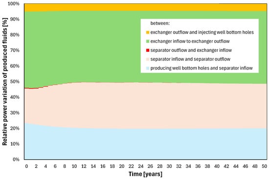
Figure 12.
Fluid power variations at various stages of the geothermal recovery system.
Other components of the energy losses include those in the producing wells, the brine separation system, and the injecting wells, which amount, on average, to 20.33%, 28.61%, and 4.56%, respectively, as shown in Table 10.

Table 10.
Relative fluid power reduction along the surface part of the geothermal recovery system.
These results suggest that the energy losses can be reduced by the technical improvement in the fluid-transporting elements (producing and injecting wells, interconnecting pipelines). The largest energy loss was identified in the water separation systems and is caused by the disposal of produced brine that carries a relatively large amount of heat energy. This component depends on the production characteristics of the reservoir, and it is, in general, beyond the recovery system control.
13. Summary and Conclusions
The problem of geothermal energy recovery from a depleted gas reservoir by the use of CO2 as an energy transporting medium was studied in an example of a Polish gas reservoir. To this aim, a simulation model was constructed that includes all the elements of the geothermal energy system:
- -
- full-scale, multiphase, thermal reservoir model,
- -
- hydrodynamic and thermodynamic models of injecting and producing wells,
- -
- thermodynamic models of heat exchangers,
- -
- models of the other elements of the system (interconnecting pipelines, water separators, etc.).
Based on these models, the following detailed tasks were performed:
- -
- detailed relationships between the parameters describing the hydrodynamic and thermal states of all the above elements,
- -
- simulation forecasts of the geothermal energy recovery process using a complete procedure simulating the cyclic flow of the energy transporting fluids through the reservoir, producing and injecting wells, and elements of surface installations,
- -
- to ensure realistic and effective conditions for the simulation forecasts, the following assumptions were made:
- total fluid production rate at the level of the historical production rates of the individual producing wells in the selected gas field,
- balanced nature of the production and injection of fluids expressed by identical volumes of these fluids under reservoir conditions–an assumption guaranteeing the maximum possible stability of reservoir pressures,
- stationarity of the fluid temperature at the outflow of the thermal energy exchangers–an assumption that allows the minimization of the number of iterations in the process of reservoir simulations,
- lack of phase transitions in the producing wells and surface installations,
- -
- the results of the simulations were presented and discussed.
Based on the work performed, the following conclusions can be formulated:
- -
- the key reservoir factors determining the amount of recovered geothermal energy are the bottom-hole temperatures, the circulated fluids stream rate, and the composition of the fluids produced by the producing wells,
- -
- the first of the above factors shows stability in the initial phase of the project; however, the length of this phase may vary in a broad range (from 5 years for the G-CS cluster, through 10 years for the G-C cluster and 15 years for the G-S cluster, up to 25 years for the G-NN cluster; in the following years, a gradual decrease in the temperature of the produced fluids is typically observed with possible exceptions–e.g., the case of the G-CS cluster),
- -
- the variability in the rate and composition of the produced fluid affects the amount of geothermal energy obtained through a differentiated decrease in the temperature of this fluid between the bottoms of the producing wells and the inflow to the heat exchanger–the smaller the heat capacity flow of the produced fluid (which is a function of the mass rates and thermodynamic properties of individual components of the fluid), the greater the decrease in this temperature across pipelines and other elements of the surface installations,
- -
- as a result of the combination of the above factors, three stages can be distinguished in the time evolution of geothermal energy recovery:
- initial stage with a variable rate and composition of produced fluid, characterized by a generally increasing power of geothermal energy recovery–the duration of this stage may significantly vary between the clusters (from 8 years in the G-N cluster up to 25 years in the G-CN cluster),
- middle stage with a relatively constant rate and composition of the produced fluid and the simultaneous stationary temperature of this fluid (between 5 years in the G-NN cluster up to 15 years in the G-C cluster),
- final stage with a constant flow and composition of the produced fluid and a gradual decrease in the temperature of this fluid (for the remaining time of the 50-year forecast period, i.e., 13 years in the G-CN cluster up to 32 years in the G-NN cluster),
- -
- the power of the recovered geothermal energy reveals a natural increase in the beginning stage of the process and a decrease in its final stage (from 1.14 MW, through the maximum value of 1.48 MW in the middle, down to 1.46 MW at the end) with relatively small deviations from its average value (1.44 MW for the studied project),
- -
- the total energy recovered from the selected gas field is 631 GWh,
- -
- the geothermal energy recovery coefficient (defined as the ratio of the power of the energy obtained in the exchangers to the net power extracted from the reservoir) amounts to 46.5% in the studied case,
- -
- factors determining the geothermal energy recovery coefficient can be ascribed to two groups:
- technical factors, including the thermal and hydrodynamic characteristics of the fluid transporting elements of the system (producing and injecting wells, interconnecting pipelines, etc.), where their energy losses can be reduced by the technical improvement of the elements and/or by their more optimum localization, generally under the control of the project implementation,
- reservoir-related factors, including water- and residual gas-to-CO2 producing ratios that are determined by the reservoir characteristics and the completion intervals of the producing wells–typically beyond the recovery system control.
The results of the studies performed for the presented and discussed case show the feasibility of the geothermal energy recovery process in the deep, depleted gas reservoir with the use of CO2 as the energy transporting medium. In general, the complexity of the obtained results proves the necessity to apply the system’s detailed modeling and simulations to reliably plan and realize a geothermal energy generation project.
Author Contributions
Conceptualization, W.S., T.S. (Tadeusz Szpunar) and R.W.; methodology, W.S., T.S. (Tadeusz Szpunar) and R.W.; software, P.Ł., M.M. and T.S. (Tomasz Siuda); validation, W.S., T.S. (Tadeusz Szpunar) and R.W.; formal analysis, W.S., T.S. (Tadeusz Szpunar) and R.W.; investigation, P.R., M.M. and T.S. (Tomasz Siuda); resources, P.R., M.M. and T.S. (Tomasz Siuda); data curation, P.R., M.M. and T.S. (Tomasz Siuda); writing—original draft preparation, W.S., P.R., M.M. and T.S. (Tomasz Siuda); writing—review and editing, W.S., M.M. and T.S. (Tomasz Siuda); visualization, P.R., M.M. and T.S. (Tomasz Siuda); supervision, W.S., T.S. (Tadeusz Szpunar) and R.W.; project administration, W.S., T.S. (Tadeusz Szpunar) and R.W. All authors have read and agreed to the published version of the manuscript.
Funding
This research was carried out as part of the project: “Analysis of the possibilities of obtaining geothermal energy from oil reservoirs”, which is funded by the Polish Ministry of Education and Science, Grant No. DK-4100-35/23. The authors would like to express their gratitude to the Polish Ministry of Science and Higher Education for funding this research.
Data Availability Statement
The original contributions presented in the study are included in the article, further inquiries can be directed to the corresponding author.
Conflicts of Interest
The authors declare no conflicts of interest.
References
- REN21, 2020: Renewables 2020: Global Status Report. Chapter 01; Global Overview. Available online: https://www.ren21.net/gsr-2020/ (accessed on 5 July 2023).
- Fridleifsson, I.B.; Bertani, R.; Huenges, E.; Lund, J.W.; Ragnarsson, A.; Rybach, L.; Hohmeyer, O.; Trittin, T. The possible role and contribution of geothermal energy to the mitigation of climate change. In Proceedings of the IPCC Scoping Meeting on Renewable Energy Sources Conference, Luebeck, Germany, 20–25 January 2008; pp. 59–80. Available online: https://web.archive.org/web/20100308014920/http:/www.iea-gia.org/documents/FridleifssonetalIPCCGeothermalpaper2008FinalRybach20May08_000.pdf (accessed on 5 July 2023).
- Bennett, K.; Li, K.; Horne, R. Power Generation Potential from Coproduced Fluids in the Los Angeles Basin. In Proceedings of the Thirty-Seventh Workshop on Geothermal Reservoir Engineering, Stanford, CA, USA, 30 January–1 February 2012; pp. 1–97. [Google Scholar]
- Erdlac, R.J.; Armour, L.; Lee, R.; Snyder, S.; Sorensen, M.; Matteucci, M.; Horton, J. Ongoing resource assessment of geothermal energy from sedimentary basins in Texas. In Proceedings of the 32 Workshop on Geothermal Reservoir Engineering, Stanford, CA, USA, 22–24 January 2007. [Google Scholar]
- Li, K.; Sun, W. A modified method for estimating geothermal resources in oil and gas reservoirs. Math. Geosci. 2014, 47, 105–117. [Google Scholar] [CrossRef]
- Liu, J.; Li, R.; Sun, Z. Exploitation and utilization technology of geothermal resources in oil fields. In Proceedings of the World Geothermal Congress 2015, Melbourne, Australia, 19–25 April 2015. [Google Scholar]
- Wang, S.; Yan, J.; Li, F.; Hu, J.; Li, K. Exploitation and utilization of oilfield geothermal resources in China. Energies 2016, 9, 798. [Google Scholar] [CrossRef]
- Lahaie, F.; Grasso, J.R. Loading rate impact on the fracturing pattern: Lessons from hydrocarbon recovery, Lacq gas field, France. J. Geophys. Res. 1999, 104, 17941–17954. [Google Scholar] [CrossRef]
- Pathak, P.; Fidra, Y.; Avida, H.; Kahar, Z.; Agnew, M.; Hidayat, D. The Arun gas field in Indonesia: Resource management of a mature field. In Proceedings of the SPE Asia Pacific Conference on Integrated Modeling for Asset Management, Kuala Lumpur, Malaysia, 29–30 March 2004; pp. 1–22. [Google Scholar]
- Dijksman, N.C. Managing a Giant: 50 Years of Groningen Gas. In Proceedings of the 2009 SPE Offshore Europe Oil Gas Conference & Exhibition, Aberdeen, UK, 8–11 September 2009; pp. 1–17. [Google Scholar] [CrossRef]
- Huang, X.; He, Y.; Wu, Y. The Feasibility study on gas field water heterostrate recycling of Longgang gas field. Chem. Eng. Oil Gas 2010, 39, 505–509. [Google Scholar]
- He, G.; Li, J.; Wang, J.; Zhang, J. New progress and outlook of development technologies in Sulige gas field. Nat. Gas Ind. 2011, 31, 12–16. [Google Scholar]
- Yu, J.; Pei, J.; Wang, L.; Zhu, J.; Zhang, H. Gas pool properties and its exploration implications of the Dongfang13-2 gravity reservoir-overpressure gas field in Yinggehai Basin. Acta Pet. Sin. 2014, 35, 829–838. [Google Scholar]
- Hettema, M.; Yperen, G.; Kortekaas, M. A Predictive Model for the Seismicity Rate of the Groningen Gas Reservoir. In Proceedings of the Fifty-Second US Rock Mechanics/Geomechanics Symposium, Seattle, WA, USA, 17–20 June 2018; pp. 1–9. [Google Scholar]
- Topór, T.; Słota-Valim, M.; Kudrewicz, R. Assessing the Geothermal Potential of Selected Depleted Oil and Gas Reservoirs Based on Geological Modeling and Machine Learning Tools. Energies 2023, 16, 5211. [Google Scholar] [CrossRef]
- Brown, D.W. A hot dry rock geothermal energy concept utilizing supercritical CO2 instead of water. In Proceedings of the Twenty-Fifth Workshop on Geothermal Reservoir Engineering Stanford University, Stanford, CA, USA, 24–26 January 2000. SGP-TR-165. [Google Scholar]
- Pruess, K. Enhanced Geothermal Systems (EGS) Comparing Water with CO2 as Heat Transmission Fluids; Lawrence Berkeley National Laboratory: Berkeley, CA, USA, 2007; Available online: https://escholarship.org/uc/item/1fr9q7q8 (accessed on 5 July 2023).
- Sowiżdżał, A.; Starczewska, M.; Papiernik, B. Future Technology Mix—Enhanced Geothermal System (EGS) and Carbon Capture, Utilization, and Storage (CCUS)—An Overview of Selected Projects as an Example for Future Investments in Poland. Energies 2022, 15, 3505. [Google Scholar] [CrossRef]
- Oil and Gas Institute—National Research Institute. Analysis of the Possibility of Acquiring Geothermal Energy from Oil Reservoirs; INiG-PIB, Statutory Work Documentation; DK-4100-40/22; Oil and Gas Institute—National Research Institute: Krakow, Poland, 2022. [Google Scholar]
- Pruess, K. Enhanced Geothermal Systems (EGS) Using CO2 as Working Fluid-A Novel Approach for Generating Renewable Energy with Simultaneous Sequestration of Carbon. Geothermics 2006, 35, 351–367. [Google Scholar] [CrossRef]
- Zhang, F.-Z.; Jiang, P.-X.; Xu, R.-N. System Thermodynamic Performance Comparison of CO2-EGS and Water-EGS Systems. Appl. Therm. Eng. 2013, 61, 236–244. [Google Scholar] [CrossRef]
- Pan, L.H.; Oldenburg, C.M.; Wu, Y.S.; Pruess, K. T2Well/ECO2N Vession 1.0: Multiphase and Non-Isothermal Model for Coupled Wellbore-Reservoir Flow of Carbon Dioxide and Variable Salinity Water; Earth Science Division, Lawrence Berkeley National Laboratory, University of California: Berkeley, CA, USA, 2011. [Google Scholar]
- Pan, L.; Oldenburg, C.M. T2Well-An Integrated Wellbore-Reservoir Simulator. Comput. Geosci. 2014, 65, 46–55. [Google Scholar] [CrossRef]
- Lei, H. Performance Comparison of H2O and CO2 as the Working Fluid in Coupled Wellbore/Reservoir Systems for Geothermal Heat Extraction. Front. Earth Sci. Sec. Econ. Geol. 2022, 10, 819778. [Google Scholar] [CrossRef]
- Pańko, A.; Szott, W.; Łętkowski, P.; Rychlicki, A. Forecasting the Watering Process of the Radlin Natural Gas Deposit Using a Simulation Model of the Deposit. Stage I–Construction of a Geological Model (in Polish: Prognozowanie Procesu Zawadnia Się Złoża Gazu Ziemnego Radlin Przy Pomocy Symulacyjnego Modelu Złoża. Etap I–Konstrukcja Modelu Geologicznego); Archiwum Instytutu Nafty i Gazu, Państwowego Instytutu Badawczego: Kraków, Poland, 2007. [Google Scholar]
- Shen, Y.; Yang, Y.; Yang, G.; Hou, X.; Ye, W.; You, Z.; Xi, J. Damage characteristics and thermos-physical properties changes of limestone and sandstone during thermal treatment from −30 °C to 1000 °C. Heat Mass Transf. 2018, 54, 3389–3407. [Google Scholar] [CrossRef]
- Somerton, W.H. Developments in Petroleum Science. In Thermal Properties and Temperature-Related Behavior of Rock/Fluid Systems; Elsevier: Amsterdam, The Netherlands, 1992; Volume 37, pp. ii–vi, 1–257. [Google Scholar]
- Thermophysical Properties. Available online: https://webbook.nist.gov (accessed on 3 April 2024).
- Szpunar, T.; Majkrzak, M. Temperature distribution in the geothermal well when using the mixture of the brine and supercritical carbon dioxide as the working fluid (in Polish: Sposób oceny rozkładu temperatury w produkcyjnym otworze geotermalnym przy dopływie mieszaniny solanki i dwutlenku węgla w zakresie warunków nadkrytycznych). Nafta-Gaz 2023, 3, 190–198. [Google Scholar] [CrossRef]
- Heidarian, E.; Hatami, T.; Rahimi, M.; Moghadasi, J. Viscosity of pure carbon dioxide at supercritical region. J. Supercrit. Fluids 2011, 56, 144–151. [Google Scholar] [CrossRef]
- Gambill, W.R. How to estimate mixture viscosity. Chem. Eng. 1959, 66, 151–152. [Google Scholar]
- Hobler, T. Ruch Ciepła i Wymienniki; Wydawnictwo Nauk Technicznych: Warszawa, Poland, 1971; 970p. [Google Scholar]
- Maples, R.E. Petroleum Refinery Process Economics; PennWell Corporation: Tulsa, OK, USA, 2000; p. 474. ISBN 0878147799/9780878147793. [Google Scholar]
- Gabolde, G.; Nguyen, J.P. Drilling Data Hendbook; Institut Francais du Petrole Publications: Paris, France, 1999. [Google Scholar]
- Walden, H. Mechanika Płynów; Wydawnictwa Politechniki Warszawskiej: Warszawa, Poland, 1991; Available online: https://bcpw.bg.pw.edu.pl/Content/164/PDF/wah_7_31.pdf (accessed on 2 June 2024).
- Mohammadian, E.; Mohamed, B.; Azdarpour, A.; Hamidi, H.; Othman, N.H.B.; Dollah, A.; SNBCMHussein Sazali, R.A.B. CO2-EOR/Sequestration: Current Trends and Future Horizons. In Enhanced Oil Recovery Processes—New Technologies; IntechOpen: London, UK, 2019; Available online: https://www.intechopen.com/chapters/69763 (accessed on 1 November 2023).
- Ouyang, L.B. New Correlations for Predicting the Density and Viscosity of Supercritical Carbon Dioxide Under Conditions Expected in Carbon Capture and Sequestration Operations. Open Pet. Eng. J. 2011, 4, 13–21. Available online: https://benthamopen.com/DOWNLOAD-PDF/TOPEJ-4-13/ (accessed on 5 June 2024). [CrossRef]
- Bała, M.; Skupio, R. Wpływ ciśnienia i temperatury na kształtowanie się parametrów sprężystych i gęstość mediów złożowych. Nafta-Gaz 2013, 69, 887–893. [Google Scholar]
- Place Software. Available online: http://www.peacesoftware.de/einigewerte/ (accessed on 5 June 2024).
- McCain, W.D. Reservoir-Fluid Property Correlations-State of the Art. SPE Res. Eng. 1991, 6, 266–272. [Google Scholar] [CrossRef]
- Robertson, E.C. Thermal Properties of Rock; Open-File Report; U.S. Geological Survey: Reston, VA, USA, 1988. [Google Scholar] [CrossRef]
- Vivas, C.; Hu, Z.; Salehi, S. Texture-Dependent Thermal Properties of Sandstone Rocks Examined by Scanning Electron Microscopy for Thermal Energy Storage Applications. ASME Open J. Eng. 2023, 2, 021054. [Google Scholar] [CrossRef]
Disclaimer/Publisher’s Note: The statements, opinions and data contained in all publications are solely those of the individual author(s) and contributor(s) and not of MDPI and/or the editor(s). MDPI and/or the editor(s) disclaim responsibility for any injury to people or property resulting from any ideas, methods, instructions or products referred to in the content. |
© 2024 by the authors. Licensee MDPI, Basel, Switzerland. This article is an open access article distributed under the terms and conditions of the Creative Commons Attribution (CC BY) license (https://creativecommons.org/licenses/by/4.0/).