Abstract
This study investigates the enhancement of vehicle warm-up performance using phase-change materials (PCMs) and various thermal storage methods. The primary objective is to utilize the thermal energy lost during engine cooling to improve the cold-start performance, thereby reducing fuel consumption and emissions. Thermal storage devices incorporating PCMs were developed and tested by measuring temperature changes and energy transfer over soaking periods of 4, 8, 16, and 24 h. The results show energy transfers of 591, 489, 446, and 315 kJ at 4, 8, 16, and 24 h, respectively. In terms of the warm-up time, the use of thermal storage devices reduced the time required to reach 70 °C by up to 24.45%, with significant reductions observed across all soaking periods. This reduction in the warm-up time directly contributes to faster engine stabilization, leading to proportional improvements in fuel efficiency and a corresponding decrease in exhaust emissions, including CO2. The findings highlight the effectiveness of PCMs in improving the engine warm-up performance and emphasize the importance of optimizing thermal storage systems to balance energy efficiency and practical application considerations. Additionally, the experimental data provide useful benchmark information for computational simulation validation, enabling the further optimization of automotive thermal management systems. Integrating a PCM-based thermal storage device can significantly enhance a vehicle’s warm-up performance, leading to reduced fuel consumption and lower emissions.
1. Introduction
Efforts to reduce carbon dioxide emissions, a primary driver of global warming, are increasing worldwide. Many countries, including South Korea, the European Union (EU), the United States, and China, are expanding institutional and financial support for eco-friendly vehicles to reduce greenhouse gas emissions in the transportation sector. The EU aims to phase out internal combustion engine vehicles by 2035 [1]. As of 2023, South Korea had approximately 25.503 million registered vehicles, with approximately 92.8% being internal combustion vehicles using gasoline, diesel, or liquified petroleum gas; 6% hybrid vehicles; 2.1% electric vehicles; and approximately 0.1% hydrogen fuel cell vehicles [2]. This distribution indicates that the proportions of internal combustion and hybrid vehicles remain significantly high. According to the government roadmap, the share of internal combustion vehicles is expected to reach approximately 60% by 2030 [3].
This underscores the need for research to improve the efficiency of internal combustion in hybrid vehicles. Specifically, developing technologies that enhance combustion efficiency and reduce emissions remains crucial. Automobile engines typically consume additional fuel during cold starts to increase engine speed for catalyst and coolant preheating [4,5,6,7]. Low catalyst temperatures reduce the efficiency of exhaust gas purification, while low coolant temperatures decrease the combustion efficiency, leading to increased carbon dioxide emissions [8]. Therefore, improving an engine’s warm-up performance without additional fuel consumption is essential. Utilizing exhaust heat and recovering waste heat are effective methods for achieving this goal. Approximately 20% of the energy from the fuel used by an engine is lost as heat, making the utilization of this energy highly effective [9].
Vehicle soak time, the period during which an engine cools to an ambient temperature after being turned off, plays a significant role in cold-start efficiency. Extended soak times can lead to increased fuel consumption and higher emissions due to the need for additional fuel during engine warm-up. Therefore, optimizing the warm-up performance by addressing the effects of soak time becomes crucial for reducing the environmental impact of internal combustion engines [8,10,11].
Traditionally, phase-change materials (PCMs) have been used in heating systems and to improve building energy efficiency [12]. However, in recent years, the application of PCM technology in the automotive industry has gained significant attention [13,14]. When applied to engine warm-up systems, these materials have the potential to significantly improve the warm-up performance without additional fuel consumption. By leveraging the thermal storage characteristics of PCMs, it is possible to efficiently supply the necessary heat during engine startup, thereby reducing fuel consumption and exhaust emissions during cold starts [11,15,16].
This study aims to enhance engine warm-up performance by using PCMs to store thermal energy lost during cooling and utilize it during cold start-ups [17]. It evaluates the effectiveness of different PCMs based on phase-change temperatures and thermal storage devices, with the goal of optimizing the warm-up performance and proposing practical solutions to reduce fuel consumption and emissions.
2. Materials and Methods
2.1. Experimental Setup and Methods
2.1.1. Selection of PCMs
To effectively assist in engine warm-ups, the stored heat must be sufficiently transferred to the coolant of a cold engine. Therefore, PCMs must have a high heat storage capacity and heat transfer efficiency [18,19]. The thermal storage device must be attached to the engine to transfer heat through the coolant. The coolant temperature of the engine typically ranges from ambient temperature when cold to below 100 °C when fully warmed up. Therefore, the phase-change temperature should be within this range [19]. If the melting point is too low, the thermal storage device may not provide sufficient energy for engine warm-up, whereas if it is too high, the phase-change energy cannot be effectively utilized, and maintaining the temperature becomes difficult owing to the large temperature difference with the ambient air [20].
Thermal storage devices must be mounted in actual vehicles to effectively utilize the waste heat from the engine. The device must be installed within the engine compartment to satisfy these conditions, and its volume must be minimized. If the PCM undergoes a liquid–gas phase change, the resulting volume and pressure changes necessitate the careful design of the thermal storage device. Therefore, in this study, materials with solid–liquid phase changes within the operating temperature range were deemed suitable [21].
The PCMs selected for this study must be chemically stable within the thermal storage device, non-reactive with the device materials, safe, non-toxic, non-flammable, and non-explosive. Therefore, it is appropriate to select a PCM with a melting point between 40 and 100 °C that satisfies these conditions [14].
2.1.2. Selection of Thermal Storage Device
A thermal storage device must allow the engine coolant to flow through and effectively transfer heat to the coolant. It must operate stably over a temperature range from room temperature to approximately 100 °C. As PCMs change in volume and pressure with temperature, thermal storage devices must be structurally robust and durable. Consequently, the device must be made of appropriate materials [22].
The materials used for the thermal storage device must not chemically react with either the coolant or the PCM and must have high thermal conductivity [22]. When selecting materials, factors such as thermal conductivity, maximum working temperature, corrosion resistance, and tensile strength must be considered. Commonly used materials for heat exchangers include copper, stainless steel, aluminum, and titanium, each with distinct properties [23], as listed in Table 1.

Table 1.
Properties of materials for thermal storage devices.
2.1.3. Fabrication of Thermal Storage Device
The thermal storage device must be designed to prevent the mixing of the PCM and coolant while ensuring effective heat exchange. It must have a sufficient volume to contain both the PCM and coolant, but remain compact enough for vehicle installation. To utilize the stored heat for engine warm-ups, the engine must be insulated to prevent heat leakage, with heat transferred only through the coolant. Vacuum insulation provides the best thermal insulation; however, other common materials include reflective insulation, fiber insulation, foam insulation, and rigid insulation [24], as listed in Table 2.

Table 2.
Insulation materials for thermal storage device.
The thermal storage device was designed to prevent the external leakage of the PCM and coolant. A thermocouple sensor was installed on top of the device to measure the PCM’s temperature and was positioned centrally within the PCM-filled area. The device was insulated using fiberglass with high thermal stability, wrapped, and secured with insulating tape to enhance fixation and thermal performance [19].
2.1.4. Bench Test Setup
A gasoline engine with a displacement of less than 1000 cc was selected for the bench test. The specifications of the engine used for the bench test are listed in Table 3.

Table 3.
Engine specifications for the bench test.
To ensure the insulation performance of the thermal storage device, a vacuum chamber was fabricated using acrylic for observation during testing. The chamber pressure was maintained at 0.7 bar using a vacuum pump and a pneumatic regulator. The bench test setup included a vacuum chamber containing the engine, a thermal storage device, temperature sensors, and flow meters.
The engine coolant flowed through two main lines: one circulating to the radiator and the other to the vehicle cabin heater core. The radiator line included a thermostat that prevented coolant flow to the radiator until it reached approximately 80 °C. If the thermal storage device is placed between the engine and the radiator, it can receive heat from the fully warmed engine; however, no heat is supplied from the cold engine owing to the lack of coolant flow. Therefore, the thermal storage device was not placed between the engine and radiator.
The heater core line used to supply heat to the vehicle cabin did not have a thermostat. In this study, the original heater core was removed and a thermal storage device was installed in the coolant line. To prevent heat loss by convection during the soaking time, a valve was closed near the thermal storage device to stop the coolant flow. Specifically, both the inlet and outlet valves of the thermal storage device, VIn and VOut, respectively, were closed to ensure that no coolant flowed through the device during the soaking period. This setup allowed the coolant to remain stationary within the thermal storage device, thereby maintaining the thermal energy stored within the system and preventing unnecessary dissipation.
2.2. Experimental Methods
2.2.1. Characteristics of PCMs
In this study, organic paraffin wax was selected to satisfy the criteria for PCMs. The selected paraffin wax was purchased from Nippon Seiro Co., Tokyo, Japan. Four types of paraffin wax were compared for selection, as listed in Table 4. The selected paraffin wax products were 115 H and 155 H. The characteristics and test results of each phase change material are listed in Table 4.

Table 4.
Characteristics of paraffin wax [25].
To utilize the PCM effectively, key properties, such as density, specific heat, phase change temperature, and thermal diffusivity information, were obtained from the Korea Testing & Research Institute. The test results are presented in Table 5.

Table 5.
Properties of the selected phase-change material.
Since engine warm-up is considered complete when the coolant temperature reaches 70 °C, the PCM must quickly raise the coolant temperature to this level. While a material with a higher phase-change temperature could effectively transfer heat to the coolant, it may have a poor insulation performance owing to the large temperature difference with ambient air. Therefore, materials that undergo a phase change between room temperature and 70 °C are suitable for thermal storage systems.
2.2.2. Characteristics of the Thermal Storage Device
The thermal storage device must ensure efficient heat exchange between the engine coolant and the PCM while maintaining the insulation performance of the coolant. Methods that facilitate rapid heat exchange between the coolant and the PCM or focus on the insulation of the coolant itself can be considered.
The thermal storage devices were designated as listed in Table 6.

Table 6.
Types of thermal storage devices.
Figure 1 and Figure 2 show the layout of the thermal storage device used in this study, while Table 7 provides the specifications.
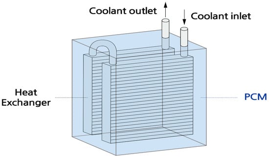
Figure 1.
Diagram of the thermal storage device with a heat exchanger.
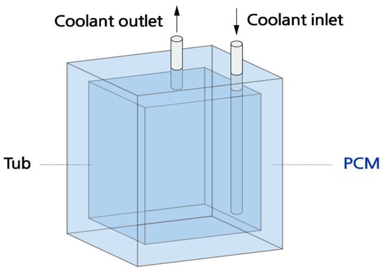
Figure 2.
Diagram of the thermal storage device with a tub.

Table 7.
Specifications of the thermal storage devices.
A thermal storage device was mounted near the engine. Additionally, thermocouple-type temperature sensors were attached to the inlet and outlet of the thermal storage device and the engine radiator lines for accurate measurements. The volumetric flow rate of the coolant entering the thermal storage device was measured using a flowmeter. Data from each sensor were collected using ETAS DAQ hardware and INCA software V7.3. The configuration of the test apparatus is shown in Figure 3. Additionally, Figure 4 and Figure 5 show the thermal storage devices installed on the engine used for testing.
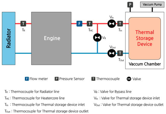
Figure 3.
Schematic diagram of the heat storage system installed in the engine test rig.
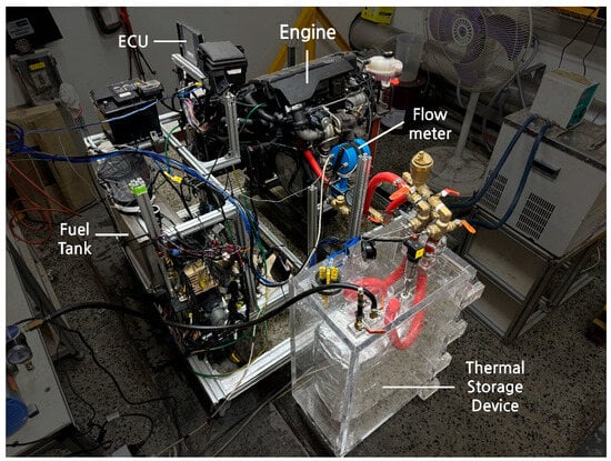
Figure 4.
Setup of bench test.
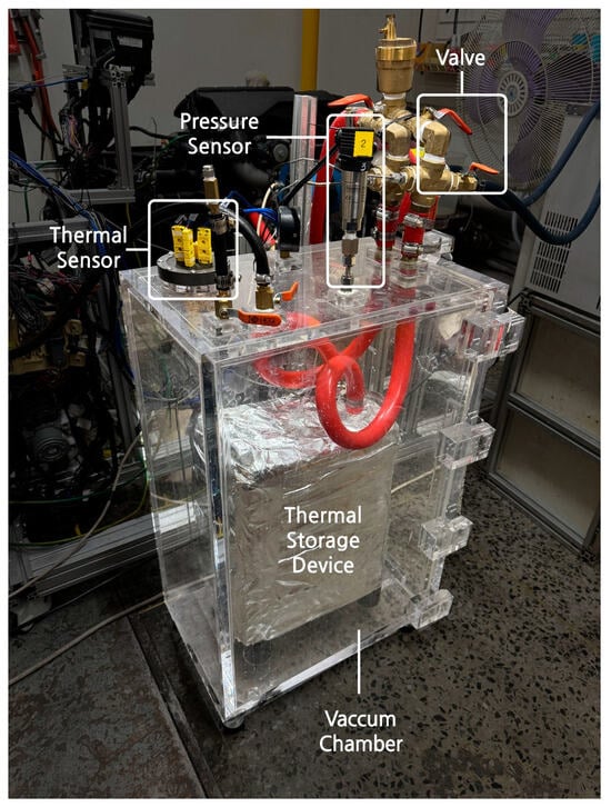
Figure 5.
Thermal storage device with a vacuum chamber.
3. Results and Discussion
3.1. Experimental Results of the Bench Test
3.1.1. Characteristics of Temperature Changes with PCMs
The engine is considered fully warmed up when the coolant temperature no longer increases and is controlled by the radiator fan. At this point, sufficient thermal energy has been transferred from the coolant to the PCMs, and the PCMs’ temperature remains stable without further changes. This situation is regarded as the end of the warm-up phase. The soaking measurement begins immediately after the engine is turned off, marking the start of the soak period.
Temperature changes in the PCMs during soaking were measured for each thermal storage device. The results are shown in Figure 6.
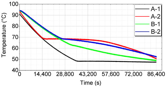
Figure 6.
Temperature changes during soaking over time.
This graph illustrates the temperature variations in the PCM for each thermal storage device (A-1, A-2, B-1, and B-2) at different soaking times. Each line represents how the PCM’s temperature changes over time, providing insights into the optimal thermal storage method and PCM selection.
A-1 shows a relatively rapid temperature drop initially but stabilizes later. This trend indicates a rapid initial energy discharge, followed by stability. However, the initial performance is poor, making it less than ideal.
A-2 exhibits a sharp initial temperature drop and then stabilizes, indicating a rapid initial energy discharge followed by stability. However, the initial drop is too steep, making it overall less stable.
B-1 starts with a slow temperature drop and then drops sharply midway before stabilizing. While the results show a good initial performance, the sharp mid-period temperature change suggests reduced long-term stability.
B-2 shows a quick initial temperature drop, but maintains the most stable temperature change over time. This indicates efficient initial energy discharge and long-term stability, making B-2 the best overall performer.
3.1.2. Temperature Changes with the Thermal Storage Device
Bench tests were divided into cases, as shown in Table 8.

Table 8.
Bench test cases.
The coolant temperature was measured at the THC, unaffected by the thermostat or coolant flow control valves, such as VB, VIn, and VOut.
The bench test results for each case are shown in Figure 7, Figure 8, Figure 9, Figure 10 and Figure 11.
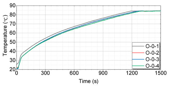
Figure 7.
Test results for engines without thermal storage devices by case.
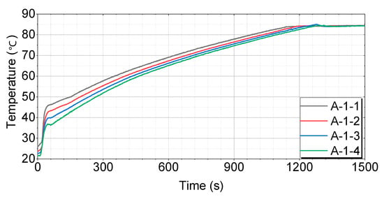
Figure 8.
Test results for engines with thermal storage device A-1.
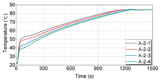
Figure 9.
Test results for engines with thermal storage device A-2.
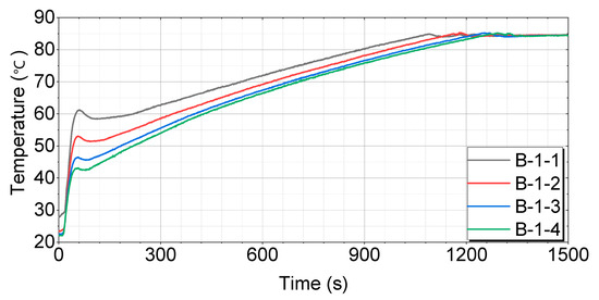
Figure 10.
Test results for engines with thermal storage device B-1.
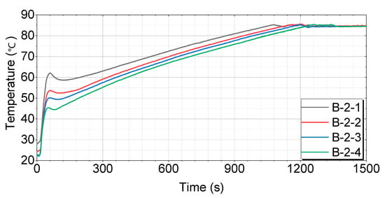
Figure 11.
Test results for engines with thermal storage device B-2.
Figure 7 shows that the O-0-1 case has the most consistent temperature-rise pattern, reaching 60 °C in 416 s, 70 °C in 687 s, and 80 °C in 1027 s. The O-0-2 case initially rises quickly, but slows down somewhat in the middle, reaching 60 °C in 461 s, 70 °C in 738 s, and 80 °C in 1088 s. The O-0-3 case exhibits a similar pattern to O-0-2, with a more pronounced slowdown in the middle, reaching 60 °C in 459 s, 70 °C in 732 s, and 80 °C in 1088 s. The O-0-4 case has the slowest temperature rise in the middle and takes the longest time to reach the final temperature, reaching 60 °C in 476 s, 70 °C in 774 s, and 80 °C in 1118 s.
Figure 8 shows that the A-1-1 case has the fastest and most consistent temperature-rise pattern, reaching 60 °C in 352 s, 70 °C in 628 s, and 80 °C in 977 s. The A-1-2 case initially rises quickly, but slows down somewhat in the middle, reaching 60 °C in 400 s, 70 °C in 679 s, and 80 °C in 1034 s. The A-1-3 case exhibits a similar pattern to A-1-2, with a more pronounced slowdown in the middle, reaching 60 °C in 446 s, 70 °C in 730 s, and 80 °C in 1083 s. The A-1-4 case has the slowest temperature rise in the middle and takes the longest time to reach the final temperature, reaching 60 °C in 463 s, 70 °C in 743 s, and 80 °C in 1096 s.
Figure 9 shows that the A-2-1 case has the fastest and most consistent temperature-rise pattern, reaching 60 °C in 300 s, 70 °C in 596 s, and 80 °C in 945 s. The A-2-2 case initially rises quickly, but slows down somewhat in the middle, reaching 60 °C in 366 s, 70 °C in 639 s, and 80 °C in 984 s. The A-2-3 case exhibits a similar pattern to A-2-2, with a more pronounced slowdown in the middle, reaching 60 °C in 442 s, 70 °C in 721 s, and 80 °C in 1079 s. The A-2-4 case has the slowest temperature rise in the middle and takes the longest time to reach the final temperature, reaching 60 °C in 460 s, 70 °C in 735 s, and 80 °C in 1083 s.
For both the B-1 and B-2 cases, which are tubular thermal storage devices, the soaking time influences the initial temperature rise. When the soaking time is short, the coolant retained inside the tubes is already at a relatively high temperature, leading to a rapid initial temperature increase. As shown in Figure 10 and Figure 11, the B-1-1 and B-2-1 cases, which were soaked for 4 h, exhibited a relatively faster rise in coolant temperature compared to the other cases. However, as the engine begins operating and the coolant circulates through the system, there is a brief drop in the temperature. This temporary decrease is caused by the inflow of cooler coolant from the coolant line. The time recorded for reaching the target temperatures was measured after this brief cooling phase, when the temperature began to rise again.
Figure 10 shows that the B-1-1 case has the fastest and most consistent temperature rise pattern, reaching 60 °C in 220 s, 70 °C in 535 s, and 80 °C in 883 s. The B-1-2 case initially rises quickly, but slows down somewhat in the middle, reaching 60 °C in 335 s, 70 °C in 628 s, and 80 °C in 969 s. The B-1-3 case exhibits a similar pattern to B-1-2, with a more pronounced slowdown in the middle, reaching 60 °C in 398 s, 70 °C in 676 s, and 80 °C in 1030 s. The B-1-4 case has the slowest temperature rise in the middle and takes the longest time to reach the final temperature, reaching 60 °C in 427 s, 70 °C in 708 s, and 80 °C in 1060 s.
Figure 11 shows that the B-2-1 case has the fastest and most consistent temperature rise pattern, reaching 60 °C in 197 s, 70 °C in 519 s, and 80 °C in 862 s. The B-2-2 case initially rises quickly, but slows down somewhat in the middle, reaching 60 °C in 324 s, 70 °C in 604 s, and 80 °C in 940 s. The B-2-3 case exhibits a similar pattern to B-2-2, with a more pronounced slowdown in the middle, reaching 60 °C in 361 s, 70 °C in 642 s, and 80 °C in 982 s. The B-2-4 case has the slowest temperature rise in the middle and takes the longest time to reach the final temperature, reaching 60 °C in 411 s, 70 °C in 698 s, and 80 °C in 1041 s.
3.1.3. Comparison of Temperature Change with Soaking Times
A comparison of each case after 4 h of soaking is shown in Figure 12.
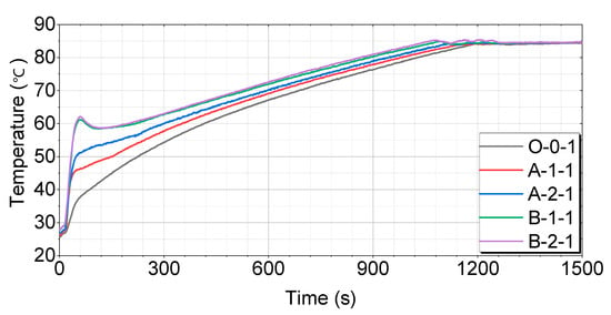
Figure 12.
Test results for 4 h of soaking as compared by the thermal storage device.
Figure 12 shows that the O-0-1 case has the slowest temperature-rise pattern, reaching 60 °C in 416 s, 70 °C in 687 s, and 80 °C in 1027 s. The A-1-1 case rises relatively quickly, reaching 60 °C in 352 s, 70 °C in 628 s, and 80 °C in 977 s. The A-2-1 case has the fastest temperature-rise pattern, reaching 60 °C in 300 s, 70 °C in 596 s, and 80 °C in 945 s. The B-1-1 case shows a very rapid rise, reaching 60 °C in 220 s, 70 °C in 535 s, and 80 °C in 883 s. The B-2-1 case reaches 60 °C in 197 s, 70 °C in 519 s, and 80 °C in 862 s, showing the fastest rise among all cases.
A comparison of each case after 8 h of soaking is shown in Figure 13.
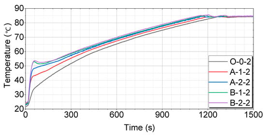
Figure 13.
Test results for 8 h of soaking as compared by the thermal storage device.
Figure 13 shows that the O-0-2 case has the slowest temperature-rise pattern, reaching 60 °C in 461 s, 70 °C in 738 s, and 80 °C in 1088 s. The A-1-2 case rises relatively quickly, reaching 60 °C in 400 s, 70 °C in 679 s, and 80 °C in 1034 s. The A-2-2 case has a faster temperature-rise pattern, reaching 60 °C in 366 s, 70 °C in 639 s, and 80 °C in 984 s. The B-1-2 case shows a very rapid rise, reaching 60 °C in 335 s, 70 °C in 628 s, and 80 °C in 969 s. The B-2-2 case reaches 60 °C in 324 s, 70 °C in 604 s, and 80 °C in 940 s, showing the fastest rise among all cases.
A comparison of each case after 16 h of soaking is shown in Figure 14.
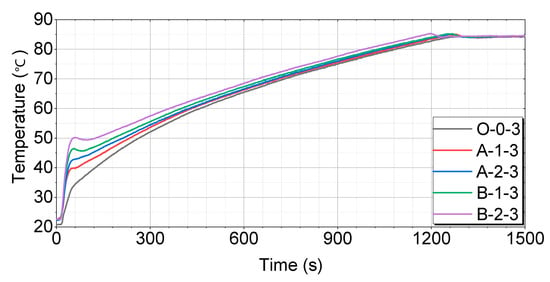
Figure 14.
Test results for 16 h of soaking as compared by the thermal storage device.
Figure 14 shows that the O-0-3 case has the slowest temperature-rise pattern, reaching 60 °C in 459 s, 70 °C in 732 s, and 80 °C in 1088 s. The A-1-3 case rises relatively quickly, reaching 60 °C in 446 s, 70 °C in 730 s, and 80 °C in 1083 s. The A-2-3 case has a faster temperature-rise pattern, reaching 60 °C in 442 s, 70 °C in 721 s, and 80 °C in 1079 s. The B-1-3 case shows a very rapid rise, reaching 60 °C in 398 s, 70 °C in 676 s, and 80 °C in 1030 s. The B-2-3 case reaches 60 °C in 361 s, 70 °C in 642 s, and 80 °C in 982 s, showing the fastest rise among all cases.
A comparison of the cases after 24 h of soaking is shown in Figure 15.
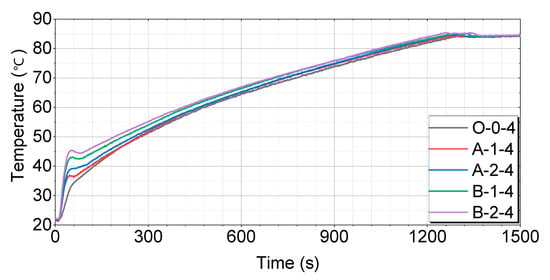
Figure 15.
Test results for 24 h of soaking as compared by the thermal storage device.
Figure 15 shows that the O-0-4 case has the slowest temperature-rise pattern, reaching 60 °C in 476 s, 70 °C in 774 s, and 80 °C in 1118 s. The A-1-4 case rises relatively quickly, reaching 60 °C in 463 s, 70 °C in 743 s, and 80 °C in 1096 s. The A-2-4 case has a faster temperature-rise pattern, reaching 60 °C in 460 s, 70 °C in 735 s, and 80 °C in 1083 s. The B-1-4 case shows a very rapid rise, reaching 60 °C in 427 s, 70 °C in 708 s, and 80 °C in 1060 s. The B-2-4 case reaches 60 °C in 411 s, 70 °C in 698 s, and 80 °C in 1041 s, showing the fastest rise among all cases.
The time taken for the coolant to reach 60, 70, and 80 °C for each case is shown in Table 9 and Figure 16.

Table 9.
Test results for warm-up times by case.
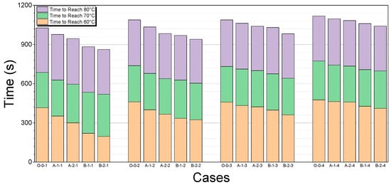
Figure 16.
Comparison of warm-up times by case.
The engine is in a cold-start state until the coolant temperature reaches 70 °C [11,16]. The following table provides a comparison of the time it takes to reach this temperature for each thermal storage device over different soaking times. The baseline for comparison is the O-0 case, which does not use a thermal storage device. The percentage difference indicates the reduction in time required for the engine coolant to reach 70 °C when using each thermal storage device compared to the O-0 case. A lower percentage difference indicates a greater improvement in the warm-up performance. As seen from the Table 10, thermal storage devices B-1 and B-2 show the most significant reductions in warm-up times, particularly for shorter soaking periods, demonstrating their superior effectiveness in utilizing stored thermal energy for engine warm-up.

Table 10.
Percentage differences for each thermal storage device over different soaking times.
These percentage differences reflect the potential for proportional improvements in fuel efficiency and reductions in exhaust emissions, including CO2 [11,16,17]. As the warm-up time is reduced, the engine reaches optimal operating conditions more quickly, leading to lower fuel consumption and a corresponding decrease in emissions by the same relative percentage.
The percentage differences in warm-up times for each thermal storage device compared to the baseline (O-0) case across various soaking periods are shown in Table 10.
3.1.4. Characteristics of Energy Transfer
The amount of heat supplied by the thermal storage device to the coolant during the test was calculated using Equation (1):
The coolant was prepared by mixing ethylene glycol and water at a 1:1 ratio, resulting in a specific heat of 0.78 kcal/kg·°C and a density of 1.0535 g/cm3. ΔT represents the temperature difference of the coolant as it passes through the thermal storage device. Qh ex is the quantity of heat, mc is the mass of the coolant, cc is the specific heat of the coolant, c is the volumetric flow rate of the coolant, and ρc is the density of the coolant. tvalve indicates the time it takes until the valve begins operating.
The heat energy supplied by each thermal storage device is listed in Table 11.

Table 11.
Amount and duration of heat energy supply by case.
The energy transfer for each case is shown in Figure 17.
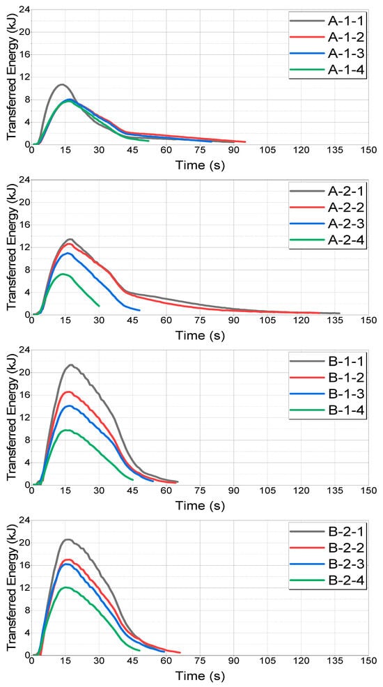
Figure 17.
Comparison of transferred energy by case.
The accumulated energy transfers for each case are shown in Figure 18.
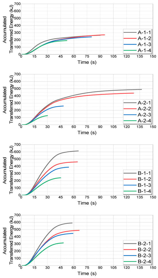
Figure 18.
Comparison of accumulated transferred energy values by case.
The transferred energy for each soaking time and thermal storage device is shown in Figure 19 and Figure 20, respectively.
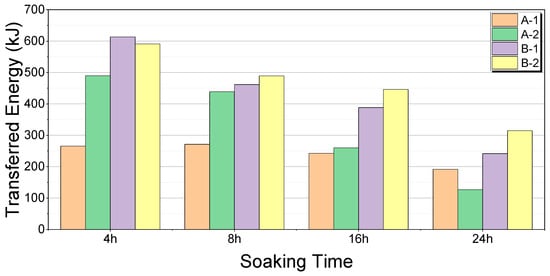
Figure 19.
Comparison of transferred energy by soaking time.
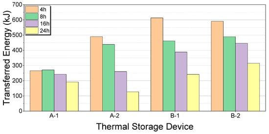
Figure 20.
Comparison of transferred energy by thermal storage device.
The maximum and minimum energy transfers for each soaking time by case and their differences are listed in Table 12.

Table 12.
Percentage difference by soaking time.
The maximum and minimum energy transfers for each thermal storage device for each case and their differences are listed in Table 13.

Table 13.
Percentage difference by thermal storage device.
At 4 h, B-1 showed the highest energy transfer, whereas A-1 showed the lowest energy transfer. The percentage difference relative to the maximum value was −56.59%. At 8 h, B-2 showed the highest energy transfer, whereas A-1 showed the lowest. The percentage difference relative to the maximum value was −44.58%. At 16 h, B-2 showed the highest energy transfer, whereas A-1 showed the lowest. The percentage difference relative to the maximum value was −45.51%. At 24 h, B-2 showed the highest energy transfer, whereas A-2 showed the lowest. The percentage difference relative to the maximum value was −59.68%.
A-1 exhibited the most stable performance, with a percentage difference of −29.15% relative to its maximum value over the soaking times. A-2 showed the greatest variation, with a percentage difference of −74.10%. B-1 was less stable, with a percentage difference of −60.69%. B-2 showed relatively stable performance, with a percentage difference of -46.70%.
At 4 h, B-1 demonstrated the highest energy transfer, whereas A-1 exhibited the lowest. The percentage difference is 130.45%. At 8 h, B-2 showed the highest energy transfer, whereas A-1 showed the lowest. The percentage difference is 80.44%. At 16 h, B-2 showed the highest energy transfer, whereas A-1 showed the lowest energy transfer. The percentage difference is 83.54%. At 24 h, B-2 showed the highest energy transfer, whereas A-2 exhibited the lowest. The percentage difference is 148.03%.
3.2. Selection of Thermal Storage Devices and PCMs
This study aims to develop a thermal storage device using PCMs to improve engine warm-up performance. Various PCMs and thermal storage devices were selected and analyzed for temperature changes over soaking times. PCMs were chosen to store and utilize the thermal energy lost during engine cooling for cold engine initiation. The selected PCMs must have a high heat storage capacity and efficiency that are suitable for actual vehicle installation. Bench tests measured the temperature changes over soaking times for the four types of thermal storage devices (A-1, A-2, B-1, and B-2) across 4, 8, 16, and 24 h soaking times.
3.2.1. Optimal Thermal Storage Device
Based on the bench test results, the B-2 thermal storage device demonstrated the highest energy transfer performance for all soaking times. The energy transferred by B-2 was 591, 489, 446, and 315 kJ at 4, 8, 16, and 24 h, respectively. This indicates that B-2 excelled in both heat storage and release, making it the most effective device tested. Despite its superior performance, the B-2 device’s total weight of 24.37 kg is significantly higher than that of the A-1 and A-2 devices, each weighing 12.63 kg. Therefore, although B-2 is highly efficient, its weight must be considered in practical applications. This highlights the trade-off between the performance and weight, which must be balanced according to the specific vehicle requirements.
3.2.2. Performance Variation with Soaking Time
The performance variation in each thermal storage device over different soaking times highlighted significant differences. The A-2 device, for example, transferred 490 kJ at 4 h but dropped to 127 kJ at 24 h, indicating instability in long-term heat storage and release. In contrast, the B-2 device maintained a relatively stable performance with minimal variation over extended soaking times, thus proving its effectiveness and reliability in long-term applications. This consistency is crucial for applications requiring a sustained thermal performance over long periods, ensuring their reliable operation without significant performance degradation.
3.2.3. Energy Efficiency Improvement
The B-2 device also showcased superior energy efficiency. At 24 h, B-2, A-1, A-2, and B-1 transferred 315, 192, 127, and 241 kJ, respectively. This demonstrates that B-2 can sustain a high performance over long periods, making it the best choice for maintaining engine warm-up performance and reducing fuel consumption and emissions. The ability of B-2 to consistently deliver a high energy output over various soaking times underscores its efficiency and suitability for automotive applications where energy efficiency is paramount.
3.2.4. Stability and Weight Considerations
Performance stability is essential for evaluating the effectiveness of thermal storage devices. The B-2 device exhibited less performance variations over longer soaking times, providing consistent and stable performances. This is significant for reducing fuel consumption and emissions by effectively utilizing PCMs in engine warm-up systems. However, the total weight of each device must be carefully considered. Devices A-1 and A-2, each weighing 12.63 kg, offered lighter alternatives to the B-2 device. Therefore, depending on the vehicle’s requirements, A-2 offers a balanced choice in performance and weight. This suggests that, while B-2 has an optimal thermal performance, A-2 might be preferable when weight is a critical constraint.
3.2.5. Practical Implications and Recommendations
Practically, the choice of a thermal storage device should be guided by the specific requirements of the vehicle and its intended application. For vehicles in which the performance is the top priority and weight constraints are less critical, the B-2 device offers the best performance. Conversely, for applications in which weight is a significant consideration, the A-2 device provides a good balance between performance and weight. Further research could explore the integration of these devices into different vehicle types and assess their performance in real-world conditions.
Table 14 provides a comprehensive summary of the content discussed in Section 3.2, offering a comparison of the thermal storage devices based on their performance, stability, weight, and suitability.

Table 14.
Performance comparison of thermal storage devices.
4. Conclusions
This study explored the use of PCMs and various thermal storage devices to enhance vehicle engine warm-up performance, a critical factor for reducing fuel consumption and emissions. The experimental results provide valuable insights into the efficiency of different thermal storage devices, specifically in terms of energy transfer, stability, and weight considerations.
The percentage difference in the time required for the coolant to reach 70 °C demonstrates the effectiveness of thermal storage devices in improving engine warm-up performance. The B-1 and B-2 thermal storage devices achieved the most significant reductions in warm-up time across all soaking periods. For example, after 4 h of soaking, the B-2 device reduced the time to reach 70 °C by 24.45%, and even at 24 h, it maintained a reduction of 9.82%. These results underscore the superior energy efficiency of the B-1 and B-2 devices, particularly for shorter soaking periods, which aligns with the goal of improving engine warm-up performance.
These percentage differences are not only indicative of faster warm-up times, but also reflect proportional improvements in fuel efficiency and reductions in exhaust emissions, including CO2. As the warm-up time decreases, the engine reaches optimal operating conditions more quickly, resulting in lower fuel consumption and emissions. For example, the reduction in the warm-up time by 24.45% for the B-2 device at 4 h suggests a similar percentage reduction in fuel consumption and emissions, thereby contributing to environmental benefits.
The B-2 thermal storage device consistently demonstrated the highest energy transfer rates across all soaking times, transferring 591 kJ at 4 h, 489 kJ at 8 h, 446 kJ at 16 h, and 315 kJ at 24 h. This performance highlights B-2’s superior capability in both heat storage and release, making it the most effective thermal storage device tested. However, the B-2 device’s total weight of 24.37 kg, compared to the 12.63 kg weight of the A-1 and A-2 devices, suggests a trade-off between performance and weight that must be carefully considered in practical applications.
Furthermore, the stability of the B-2 device was evident from its consistent performance with minimal variations over extended soaking times. In contrast, the A-2 device, which showed a strong initial energy transfer of 490 kJ at 4 h, exhibited a significant drop to 127 kJ at 24 h, indicating instability in long-term heat storage and release. This consistency in performance is particularly important for applications requiring sustained thermal performance over long periods, ensuring reliable operation without significant performance degradation.
In addition to improving engine warm-up performance, the use of thermal storage devices with PCMs presents the potential for broader applications in waste heat recovery beyond just engine coolant. These devices could be adapted to capture and utilize waste heat from other sources within the vehicle, further enhancing overall energy efficiency and reducing fuel consumption and emissions.
In summary, this study confirms that integrating a thermal storage device with PCMs can significantly enhance a vehicle’s warm-up performance, contributing to reduced fuel consumption and lower emissions. The experimental data collected in this research also provide valuable benchmark data that can be effectively used for computational simulations, facilitating the further optimization of automotive thermal management systems. Future work should focus on optimizing these devices for specific vehicle types and operational conditions, with an emphasis on improving material efficiency and further reducing weight without compromising performance. Moreover, expanding the application of these thermal storage devices to other waste heat recovery systems within the vehicle could provide additional benefits to overall energy management.
Author Contributions
Conceptualization, J.L. (Juho Lee) and K.L.; Methodology, J.L. (Juho Lee); Software, J.L. (Juho Lee) and J.L. (Jungkoo Lee); Validation, J.L. (Juho Lee) and J.L. (Jungkoo Lee); Formal analysis, J.L. (Juho Lee) and J.L. (Jungkoo Lee); Investigation, J.L. (Juho Lee); Resources, K.L.; Data curation, J.L. (Juho Lee) and J.L. (Jungkoo Lee); Writing—original draft, J.L. (Juho Lee); Writing—review & editing, J.L. (Juho Lee); Visualization, J.L. (Juho Lee); Supervision, K.L.; Project administration, K.L.; Funding acquisition, K.L. All authors have read and agreed to the published version of the manuscript.
Funding
This research was supported by the Technology Innovation Program (or Industrial Strategic Technology Development Program) (20018346, Development of an adsorption-desorption system to capture carbon dioxide emitted from commercial vehicles), funded by the Ministry of Trade, Industry & Energy (MOTIE, Korea).
Data Availability Statement
The original contributions presented in the study are included in the article.
Conflicts of Interest
The authors declare no conflict of interest.
References
- EU Ban on the Sale of New Petrol and Diesel Cars from 2035 Explained. Available online: https://www.europarl.europa.eu/topics/en/article/20221019STO44572/eu-ban-on-sale-of-new-petrol-and-diesel-cars-from-2035-explained#:~:text=In%20June%202022%2C%20Parliament%20backed,cars%20and%2050%25%20for%20vans (accessed on 1 June 2024).
- Vehicle Registration Status in South Korea. Available online: https://www.index.go.kr/unity/potal/main/EachDtlPageDetail.do?idx_cd=1257 (accessed on 1 June 2024).
- Development Strategy for South Korea’s Future Automotive Industry: 2030 National Roadmap. Available online: https://nsp.nanet.go.kr/plan/subject/detail.do?newReportChk=list&nationalPlanControlNo=PLAN0000030876 (accessed on 1 June 2024).
- Ramadhas, A.; Xu, H.-M.; Liu, D.; Tian, J.-Y. Key Factors Affecting the Cold Start of Diesel Engines. Int. J. Green Energy 2015, 2015. [Google Scholar] [CrossRef]
- Di Battista, D.; Cipollone, R. Improving Engine Oil Warm Up through Waste Heat Recovery. Energies 2017, 11, 10. [Google Scholar] [CrossRef]
- Hedinger, R.; Elbert, P.; Onder, C. Optimal Cold-Start Control of a Gasoline Engine. Energies 2017, 10, 1548. [Google Scholar] [CrossRef]
- Reiter, M.S.; Kockelman, K.M. The problem of cold starts: A closer look at mobile source emissions levels. Transp. Res. Part D Transp. Environ. 2016, 43, 123–132. [Google Scholar] [CrossRef]
- Gao, J.; Tian, G.; Sorniotti, A.; Karci, A.E.; Di Palo, R. Review of thermal management of catalytic converters to decrease engine emissions during cold start and warm up. Appl. Therm. Eng. 2019, 147, 177–187. [Google Scholar] [CrossRef]
- Kauranen, P.; Elonen, T.; Wikström, L.; Heikkinen, J.; Laurikko, J. Temperature optimisation of a diesel engine using exhaust gas heat recovery and thermal energy storage (diesel engine with thermal energy storage). Appl. Therm. Eng. 2010, 30, 631–638. [Google Scholar] [CrossRef]
- Pucher, G.R.; Gardiner, D.P.; Mallory, R.W.; Bardon, M.F. The Effects of Reduced Ambient Temperatures on the Warm-Up Fuel Consumption Behavior of Gasoline Fuelled Automobiles; SAE Technical Paper 952563; SAE International: Warrendale, PA, USA, 1995. [Google Scholar]
- Bielaczyc, P.; Merkisz, J. Exhaust Emission from Passenger Cars During Engine Cold Start and Warm-Up; SAE Technical Paper 970740; SAE International: Warrendale, PA, USA, 1997. [Google Scholar]
- Akeiber, H.; Nejat, P.; Majid, M.Z.; Wahid, M.A.; Jomehzadeh, F.; Famileh, I.Z.; Calautit, J.K.; Hughes, B.R.; Zaki, S.A. A review on phase change material (PCM) for sustainable passive cooling in building envelopes. Renew. Sustain. Energy Rev. 2016, 60, 1470–1497. [Google Scholar] [CrossRef]
- Li, C.; Gou, F.; Yu, R. Application of Phase Change Heat Storage Technology in Vehicle Engineering Field. IOP Conf. Ser. Earth Environ. Sci. 2020, 615, 012052. [Google Scholar] [CrossRef]
- Sharma, A.; Tyagi, V.V.; Chen, C.R.; Buddhi, D. Review on thermal energy storage with phase change materials and applications. Renew. Sustain. Energy Rev. 2009, 13, 318–345. [Google Scholar] [CrossRef]
- Roberts, A.; Brooks, R.; Shipway, P. Internal combustion engine cold-start efficiency: A review of the problem, causes and potential solutions. Energy Convers. Manag. 2014, 82, 327–350. [Google Scholar] [CrossRef]
- Andrianov, D.I.; Manzie, C.; Brear, M.J. A Methodology for Minimising Emissions Constrained Cold Start Fuel Consumption; SAE Technical Paper 2012-01-0894; SAE International: Warrendale, PA, USA, 2012. [Google Scholar]
- Pielecha, J.; Skobiej, K.; Kurtyka, K. Testing and evaluation of cold-start emissions from a gasoline engine in RDE test at two different ambient temperatures. Open Eng. 2021, 11, 425–434. [Google Scholar] [CrossRef]
- Khan, M.I.; Asfand, F.; Al-Ghamdi, S.G. Progress in research and development of phase change materials for thermal energy storage in concentrated solar power. Appl. Therm. Eng. 2023, 219, 119546. [Google Scholar] [CrossRef]
- Shon, J.; Kim, H.; Lee, K. Improved heat storage rate for an automobile coolant waste heat recovery system using phase-change material in a fin–tube heat exchanger. Appl. Energy 2014, 113, 680–689. [Google Scholar] [CrossRef]
- Jankowski, N.R.; McCluskey, F.P. A review of phase change materials for vehicle component thermal buffering. Appl. Energy 2014, 113, 1525–1561. [Google Scholar] [CrossRef]
- Kenar, J.A. The use of lipids as phase change materials for thermal energy storage. Lipid Technol. 2014, 26, 154–156. [Google Scholar]
- Park, S.; Woo, S.; Shon, J.; Lee, K. Experimental study on heat storage system using phase-change material in a diesel engine. Energy 2017, 119, 1108–1118. [Google Scholar] [CrossRef]
- Axsom, T. Heat Exchanger Material Selection. Available online: https://www.fictiv.com/articles/heat-exchanger-material-selection (accessed on 1 June 2024).
- Types of Insulation. Available online: https://www.energy.gov/energysaver/types-insulation (accessed on 1 June 2024).
- Characteristics of Paraffin Wax Types. Available online: https://www.seiro.co.jp/en/product_en/list/detail?id=506 (accessed on 1 June 2024).
Disclaimer/Publisher’s Note: The statements, opinions and data contained in all publications are solely those of the individual author(s) and contributor(s) and not of MDPI and/or the editor(s). MDPI and/or the editor(s) disclaim responsibility for any injury to people or property resulting from any ideas, methods, instructions or products referred to in the content. |
© 2024 by the authors. Licensee MDPI, Basel, Switzerland. This article is an open access article distributed under the terms and conditions of the Creative Commons Attribution (CC BY) license (https://creativecommons.org/licenses/by/4.0/).