Review

Recent Advances in Numerical Simulation of Ejector Pumps for Vacuum Generation—A Review

CATMech—Department of Fluid Mechanics, Universitat Politecnica de Catalunya, ES-08222 Terrassa, Catalunya, Spain
*
Author to whom correspondence should be addressed.
Energies 2024, 17(17), 4479; https://doi.org/10.3390/en17174479
Submission received: 15 July 2024 / Revised: 27 August 2024 / Accepted: 30 August 2024 / Published: 6 September 2024
(This article belongs to the Section J1: Heat and Mass Transfer)

Abstract

:
This review paper provides an overview of recent advances in computational fluid dynamics (CFD) simulations of ejector pumps for vacuum generation. It examines various turbulence models, multiphase flow approaches, and numerical techniques employed to capture complex flow phenomena like shock waves, mixing, phase transitions, and heat/mass transfer. Emphasis is placed on the comprehensive assessment of flow characteristics within ejectors, including condensation effects such as nucleation, droplet growth, and non-equilibrium conditions. This review highlights efforts in optimizing ejector geometries and operating parameters to enhance the entrainment ratio, a crucial performance metric for ejectors. The studies reviewed encompass diverse working fluids, flow regimes, and geometric configurations, underscoring the significance of ejector technology across various industries. While substantial progress has been made in developing advanced simulation techniques, several challenges persist, including accurate modeling of real gas behavior, phase change kinetics, and coupled heat/mass transfer phenomena. Future research efforts should focus on developing robust multiphase models, implementing advanced turbulence modeling techniques, integrating machine learning-based optimization methods, and exploring novel ejector configurations for emerging applications.

1. Introduction

Ejectors stand as versatile and vital components in the realm of fluid dynamics, finding application across a spectrum of industries ranging from refrigeration and air conditioning to aerospace propulsion. These devices harness the kinetic energy of a high-pressure primary flow to induce and accelerate a secondary fluid stream based on the principle of entrainment. A typical ejector comprises main components such as primary nozzle, mixing chamber, throat, and diffuser. Figure 1 shows the schematic of a typical supersonic ejector’s main components. The morphology of the ejector may be different depending on the application. In the case of Figure 1, the convergent–divergent nozzle of the primary flow indicates that this is a gas and the flow must be supersonic in the mixing chamber. In other cases, this nozzle may be simply convergent or even straight, and its position in the suction chamber may differ. Notable benefits of ejectors include their simple design, no moving parts, no electricity required, no contamination, and scalability to accommodate various flow rates and pressure requirements. The drawbacks of ejectors are low efficiency, limited suction capability, dependence on motive fluid properties, complexity in design and operation, as well as noise and vibration.
Among the recently published review papers, in 2015, Chen and colleagues [1] pointed out the critical role of ejectors with respect to energy recovery systems and their integration with other technologies, highlighting the necessity for more dependable ejector and system modeling under both steady-state and transient conditions. In 2016, Elbel et al. [2] presented an overview of advancements in utilizing ejectors for recovering expansion work in vapor-compression systems. They suggested further research and development efforts in this field to enhance the adaptability of ejectors for broader applications. In the same year, Besagni et al. [3] conducted a comprehensive review on ejector refrigeration systems, exploring their diverse applications alongside various other technologies. They presented an analysis of the relationship between the working fluids and ejector performance, emphasizing historical, current, and future trends. Also, in 2016, Little and Garimella [4] offered a review while highlighting particular aspects of ejector traits and their application within chiller systems. In 2019, Aidoun et al. [5,6] contributed to two review papers. The first paper [5], focusing on single-phase ejectors, outlined recent research on heat-driven ejectors and ejector-based machines using low-boiling-point fluids. They discussed ejector physics principles, recent technological developments, and achievements in thermally activated ejectors for compressible fluids. The emphasis was on design, operation, theoretical and experimental approaches, complex phenomena analysis, and performance evaluation. The subsequent paper by Aidoun et al. [6], which concentrated on two-phase ejectors, provided substantial insights into the design, functioning, and effectiveness of these components. They extensively discussed the impact of geometry, operating conditions, and recent advancements in theoretical and experimental approaches, evaluation methods, and applications. In the same year, Tashtoush et al. [7] focused on various geometrical factors influencing ejector performance, such as entrainment ratio, pressure ratio, primary nozzle position, area ratio, and mixing suction length. They also covered mathematical models for studying ejector behavior, experimental flow visualization techniques, primary ejector refrigeration systems, and the effects of different working fluids on system performance. In 2021, Koirala et al. [8] aimed to evaluate primary water jet ejectors for active vapor transport and condensation in compact domestic water desalination systems, with the goal of replacing vacuum pumps and condensers. In the same year, Besagni [9] analyzed ejector technology, refrigerant properties, and their impact on performance, categorizing the technologies into past, present, and future trends.
Figure 1. Schematic of a typical ejector indicating its four main components including converging–diverging nozzle, suction chamber, mixing chamber, and diffuser, reproduced from [7]. Copyright© 2024 Elsevier Masson SAS. All rights reserved.
Energies 17 04479 g001
For a significant time, the design of ejector systems has largely leaned toward empirical or semi-empirical methods due to the intricate flow physics involved. Leveraging numerical techniques and mathematical models, CFD simulations provide a virtual window into the inner workings of ejectors, enabling detailed analysis of pertinent parameters. By synthesizing the collective knowledge and expertise from diverse disciplines including fluid mechanics and numerical analysis, this review seeks to offer a holistic understanding of the intricacies involved in the CFD-based investigation of ejectors.Given the significant increase in published articles on ejectors over the past two decades and the categorization of various relevant topics, articles published between 2014 and 2024 were selected based on their alignment with the established categorization in this study.

2. Fundamental of Ejectors

Ejectors function to convey energy from either a liquid or gas primary fluid to a secondary fluid. The following processes occur in the components of an ejector:
  • The primary fluid’s pressure energy is converted into kinetic energy within the nozzle.
  • The low-velocity secondary fluid is entrained and mixed with the high-velocity primary fluid in the mixing throat, driven by viscous friction and the suction created by the pressure drop at the nozzle exit.
  • The combined fluid’s kinetic energy is transformed back into pressure energy within the diffuser.
Within the mixing region, turbulent shear stress generates a velocity distribution that steeply increases toward the ejector axis. If the primary flow is supersonic, a series of shock waves will appear along the mixing zone, undergoing multiple reflections. Additionally, phase-change phenomena inside the ejectors may happen in different ways depending on the application. The condensation effect is one of the most sophisticated phenomena which may occur due to the expansion of either primary or secondary fluid within the two-phase boundary. Due to the high velocity, compressibility, and turbulence involved, the study of this effect becomes more intricate [10,11,12,13]. According to Figure 1, some of the main parameters impacting the performance of ejector including entrainment ratio, pressure ratio, and efficiency of ejector are defined in the following.

2.1. Entrainment Ratio

The entrainment ratio M refers to the ratio of entrained fluid flow rate m ˙ s to the primary fluid flow rate m ˙ p , indicating the effectiveness of fluid entrainment and mixing within the ejector system, which is defined as follows [14]:
M = m ˙ s m ˙ p

2.2. Pressure Ratio

The pressure ratio N represents the ratio of pressure increase in the secondary flow to the pressure drop in the primary flow by the ejector system, which can be defined as follows [14]:
N = P d P s P p P d
where P d , P s , and P p denote diffuser outlet pressure, secondary fluid pressure, and primary fluid pressure, respectively.

2.3. Efficiency of Ejector

Efficiency of ejector η , in essence, refers to the relationship between the power generated by the ejector (output power E ˙ o u t ) and the power consumed by the ejector (input power E ˙ i n ). Based on the one-dimensional theory assuming that mixing is completed in the constant area mixing throat and that the spacing between the nozzle exit and the mixing throat entrance is zero, the efficiency of the ejector can be defined as follows [15,16]:
η = E ˙ o u t E ˙ i n = M N
where M, N are entrainment ratio and pressure ratio.

2.4. Subsonic Ejectors

Subsonic ejectors can operate in three modes, namely stable, critical, and unstable, as shown in Figure 2. At the stable mode, the entrainment ratio stays constant until it reaches its critical value of compression ratio. At the critical compression ratio, the suction reaches its peak; in other words, it is called the maximum discharge point (MDP). At the unstable mode, fluctuations and declines in the entrainment ratio are noted, along with reversed flows. The reversed flow condition occurs when the entrainment ratio reaches its minimum threshold, causing the motive flow to reverse within the system.

2.5. Supersonic Ejectors

The supersonic ejector operates in three distinct modes, illustrated in Figure 3. In the critical mode, also known as double-choking, the entrainment ratio remains constant due to the choking of both primary and secondary flows. In the subcritical mode, or single-choking, the primary flow is choked, leading to a linear change in entrainment ratio with back pressure. In the malfunction mode, referred to as back-flow, the reversal of the secondary flow causes the ejector to malfunction.

2.6. Vacuum Ejectors

Vacuum ejectors are widely used to create vacuum environments without the need for electricity and without producing contaminants. Their operation typically involves three key stages, as illustrated in Figure 4: vacuum generation (response time t 1 ), vacuum holding ( t 2 ), and vacuum release ( t 3 ). Key considerations for vacuum ejectors include the following [17]:
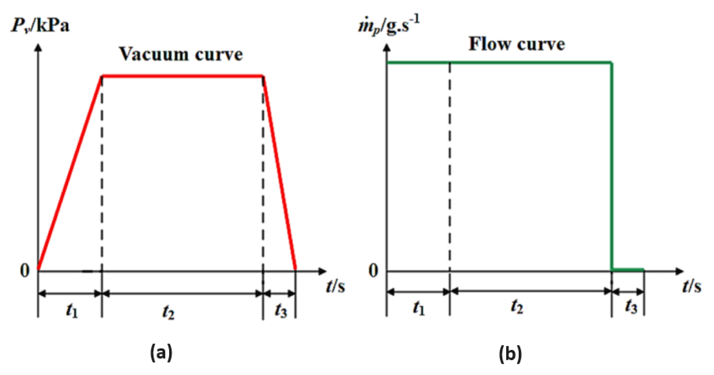
  • Response Time: The vacuum response time is the time at which the vacuum level reaches 63 % of the maximum vacuum level. Response time is crucial for system efficiency. A longer response time can decrease overall work efficiency and increase air consumption. Therefore, minimizing t 1 is essential for optimal performance.
  • Vacuum Holding Time: This stage represents a significant portion of the work cycle, typically accounting for 50–80% of the total time. During this period, high-pressure air is continuously supplied to make up for leakage and maintain the desired vacuum level.
In real-world applications, response time should be prioritized, meaning the supply pressure should be kept as low as possible to reduce energy consumption. However, most single-stage vacuum ejectors reach their maximum vacuum level of 90 kPa when the motive pressure is 0.55 MPa, and the entrainment ratio is of about 0.5 [17]. As a result, the energy consumption of the vacuum ejector cannot be overlooked. Enhancing the entrainment capacity or reducing air consumption during the vacuum holding stage would significantly contribute to the energy-efficient operation of vacuum systems [18].

2.7. Applications

Depending on the specific use case, the primary fluid may be either liquid or gas, while the secondary fluid can be liquid, gas, or solid particles [19,20,21,22].

2.7.1. Single-Phase and Two-Phase Ejectors

Single-phase ejectors work with a single phase, typically either gas or liquid. They find applications in various industries wherein fluid transportation or mixing is required. Two-phase ejectors generally refer to the condensing ejector (vapor stream condenses in the ejector), or to the conventional two-phase ejector (two-phase, liquid–vapor flow throughout the ejector). Finding an increased use as expansion devices, they reduce throttling losses and recover expansion work (replacement of expansion valves) in heat pumps, air-conditioning, and refrigeration systems.
In summary, ejectors involve a wide range of technologies and applications such as the following:
  • Vacuum pumping and degassing; power cycle [23].
  • Desalination.
  • Air-conditioning, heating, and refrigeration [24,25].
  • Aeronautics and space applications.
  • Enhancing gas turbine performance [26].
  • Fluid mixing and separation [27].
  • Fuel cell applications [28].
  • Natural gas recompression.
In addition, the exploration of applications in emerging technologies, such as energy storage and waste heat recovery systems [6,29], present exciting opportunities for further research.

2.7.2. Geography of Ejectors Research

Geographically, research on the applications of ejectors is dispersed globally, with prominent centers in regions like North America, Europe, Africa, and Asia-Pacific. This distribution often aligns with the necessities and concentration of industries requiring technologies such as vacuum technology, distillation, desalination, refrigeration, etc. For instance, there are some studies in the literature reporting on methods consisting in purifying Persian Gulf seawater using desalination systems based on vacuum ejectors [30,31]. Also, other noteworthy practical studies available in the literature refer to the use of vacuum ejectors in advanced MED solar desalination plants in Almeria, Spain [32,33]. The bar chart in Figure 5 provides a visual representation of the contribution of 47 counties in the world in publishing articles associated with the numerical simulation of ejectors from 2014 to 2024.

3. Computational Fluid Dynamics Modeling of Ejectors

Computational fluid dynamics is a powerful tool that helps in creating detailed models to capture the complex fluid interactions and turbulence within ejectors [34]. It also allows for the optimization of ejector design by providing insights into pressure distribution, velocity fields, and mixing behaviors. In the following, various aspects associated with CFD simulation of ejectors including single-phase and two-phase simulations, numerical methods, geometry and meshing considerations, boundary conditions, solver and software, turbulence modeling, validation approaches, parametric studies, optimization strategies, entropy loss analysis, entrainment ratio behavior, internal flow visualization, and investigations into heat and mass transfer properties. By examining these key areas, we aim to provide a comprehensive overview of the current state and future directions of CFD applications in ejector research and design.

3.1. Single-Phase Ejector CFD Simulation

As indicated in Table 1, from the perspective of primary and secondary flows subjected to single-phase ejectors in recent CFD studies, gas–gas both as ideal gas [18,35], air–air both as ideal gas [36,37], steam–steam both as ideal saturated steam [38], and steam–steam both as ideal gas [39] were taken into account as primary and secondary flows subjected to single-phase ejectors. Hence, pure hydrogen-mixed H2/N2 was used by Singer et al. [40] and nitrogen–air by Li et al. [41], as primary and secondary flows in a single-phase ejector.

3.2. Two-Phase Ejectors CFD Simulation

Modeling two-phase flows including phenomena like flashing liquid or vapor condensation remains challenging. Many aspects at the local scale, such as nucleation characteristics and the growth of bubbles and droplets, are still not fully understood. Developing accurate models for the complex gas–liquid interface and transfer mechanisms requires more sophisticated approaches, often relying on empirical correlations or assumptions that have yet to be rigorously tested [6]. According to data available in Table 1, saturated steam–water [42], subcooled water–vapor [46], vapor–liquid [47], and wet steam [49,51] were employed as primary and secondary flows, functioning in two-phase ejectors. In addition, Table 2 provides information about the two-phase models used by different authors in this review. According to Table 2, Eulerian–Eulerian models have been commonly employed by authors. Other multiphase models [52] which could be used in ejector simulations include the following:
  • Volume of fluid (VOF): Suitable for simulating fluids with a sharp interface, such as liquid–gas flows.
  • Mixture model: often used for simulating homogeneous multiphase flows or when the interface is not of primary interest.
  • Lagrangian–Eulerian model: Suitable for particle-scale phenomena which can be modeled using fundamental principles of physics.

3.3. Numerical Methods

Various numerical techniques including finite volume method, finite difference method, and the finite element method can be used for computational fluid dynamics simulations of ejectors. The finite volume method is more conventional for solving the Navier–Stokes equations and other governing equations associated with flow inside ejectors. Some key aspects of the finite volume method include second-order upwind discretization scheme [18,35,36,39,40,41,44,45,48,49,50] and coupled algorithm for pressure–velocity coupling [35,36,39,40,41,44,48,49], which have been widely used among the papers in this review. Although Koirala et al. [46] employed several numerical schemes in their study, they utilized the phase-coupled SIMPLE scheme (also used by [44]) for phase coupling. The least-squares cell-based model was used for the spatial discretization of gradients. The pressure was discretized using the PRESTO model. For the remaining terms, they applied the first-order upwind scheme.

3.4. Geometry and Mesh

Here, the geometry and computational mesh used in CFD studies of ejectors are reviewed. Various types of geometries used are presented in Table 1. Chai et al. [42], Hou [38], Koirola et al. [46], and Banu and Mani [39] utilized three-dimensional models, while Niu and Zhang [18], Talebiyan et al. [35], Singer et al. [40], Feng et al. [53], Kus and Madjeski [44], Tavakoli et al. [36], Dadpour et al. [45], Wen et al. [47], Macia et al. [37], Han et al. [48] Giacomelli et al. [49], and Ariafar et al. [50] used either 2D or 2D axis-symmetric models of ejectors in their simulations. According to Besagni et al. [9], there are no substantial differences in the results obtained from 2D and 3D models. This claim is further supported by Feng et al. [43], who validated the assertions made by previous researchers [54] regarding the accuracy of two-dimensional models in predicting flow behavior. Thus, more investigations need to be undertaken about the comparison between 2D and 3D ejector models. With regard to types of mesh, when structured, they consist of hexahedral (3D) or quadrilateral (2D) elements, and unstructured mesh consist of tetrahedral (3D) or triangular (2D) elements. Also, Table 1 demonstrates the number of elements in the studies.

3.5. Boundary Conditions

Properly defining boundary conditions is crucial for the accurate simulation of ejectors, i.e., specifying inlet conditions, outlet conditions, and wall boundary conditions. Table 3 depicts all types of boundary conditions used in detail. While pressure boundary conditions were mostly used for both the inlet and outlet of the ejector, Chai et al. [42], Singer et al. [40], and Tavakoli et al. [36] used mass flow rate as inlet boundary conditions of primary flow. Hence, Kus and Madjeski [44] utilized the velocity condition alongside pressure for the primary inlet boundary condition. Moreover, generally, the inside wall of the ejector is assumed to be adiabatic and a non-slip condition for the wall is considered.

3.6. Solvers and Software

Prior researchers indicated that the selection of appropriate solvers and turbulence models [65] significantly influences the accuracy of ejector simulations in CFD studies. As depicted in Table 3, various solver algorithms, such as pressure-based [18,35,38,42,46] or density-based solvers [37,39], were employed based on the flow regime and physics of the ejector system. With regard to commercial packages, different versions of Ansys Fluent was widely used by the authors. However, Lucas et al. [66], Novais and Scalon [67], Macia et al. [37], Fang et al. [53], and Klyuyev et al. [68] used Open FOAM in recent years.

3.7. Turbulence Modeling

Owing to the intricacy of flow structure comprising large and small-scale vorticities, choosing a robust turbulence model is crucial to fully resolve the turbulent flow inside ejectors. Direct Numerical Simulation (DNS), Reynolds-averaged Navier–Stokes (RANS)-based turbulence models or Large Eddy Simulation (LES) could be utilized to model turbulent flow behavior within ejectors. DNS and LES solutions encounter difficulties due to highly complex vortex processes at very small scales. Both DNS and LES require a fine computational grid, small time-step iterations, and are dependent on the Reynolds number. Although RANS-based turbulence models have been predominantly used by the authors in recent years, the use of LES simulation by Zaheer et al. [69] and Croquer et al. [70] is noteworthy. Among the RANS-based turbulence models, the k- ω SST [18,35,36,37,41,47] has been favored as a strong turbulence model in capturing flow features inside ejectors compared to other turbulence models. However, others used standard k- ϵ [36,42] and realizable k- ϵ [38,51] in their simulation. More recently, Singer et al. [40] employed Reynolds-averaged Navier–Stokes (RANS) equations to characterize turbulent flow within an ejector in PEM fuel cell applications. They found that the RSM GEKO turbulence model, with adjusted parameters, effectively achieved an average deviation of 6.1% across the entire operating range, outperforming traditional eddy viscosity turbulence models in predicting flow features, and in particular shock propagation inside the hydrogen ejectors. Table 3 provides detailed information about turbulence modeling and wall function used by authors. Additionally, as outlined in Table 2, the k- ω SST, as the best turbulence model in simulation of the flow inside ejectors, was emphasized by Talebyian et al. [35] and Chen et al. [47]. However, Tavakoli et al. [36] reported that there were no differences between the results yielded by k- ω SST and standard k- ϵ in their work. To the best of the authors’ knowledge, the literature lacks studies that perform a combined LES–RANS or LES–DNS approach for turbulence modeling of flow inside ejectors. Such an approach could be effective in fully capturing both the large and small-scale eddies associated with turbulent flow in ejectors.

3.8. Validation and Verification

The validation and verification of CFD models against experimental data, analytical solutions, or numerical results are essential steps to ensure the reliability and accuracy of simulated ejector performance [71]. Experimentally, there have not been too many references for validation of two-phase ejectors flow features. However, Moore [63], Moses and Stein [60], and Bakhtar [64] were the first researchers who provided test rigs regarding two-phase steam condensation, which are still widely used as case for validation. Subsequently, Kwidzinsky [72,73] published an experimental study on two-phase steam ejectors. Also, other experimental data related to gaseous ejectors by Karthick et al. [55,74] and Al-Rbaihat et al. [75] are available in the literature review. An important point among the published experimental works is the lack of experimental data based on subcooled water as the primary fluid and steam as the secondary fluid, corresponding to the condensation or evaporation process in the ejector systems. Therefore, the necessity of conducting such an experiment is inevitable. Table 3 demonstrates the validation or verification cases used by selected papers in this review.

3.9. Parametric Study

Conducting a parametric study involves systematically varying input parameters, such as nozzle exit position, throat area ratio, or operating conditions, to analyze their effects on ejector performance and optimize design parameters. The following discusses some of the most critical aspects of recent parametric studies, including nozzle exit position, nozzle area ratio, mixing throat diameter, along with other geometric aspects and operating conditions.

3.9.1. Nozzle Exit Position

The nozzle exit position NXP parameter is defined as the distance between the exit plane of the primary nozzle and the entry plane of the converging entrance zone of the mixing chamber, as shown in Figure 6.
Han [48] identified an optimal NXP value of 10 mm for a steam ejector refrigeration system. Exceeding this optimum value led to decline in the enrainment ratio and performance of the ejector. Tavakoli et al. [36] investigated the influence of NXP and mixing chamber height to reach the highest entrainment ratio. They found that the optimal ratios of the NXP to the primary nozzle throat height, and the mixing chamber height to the primary nozzle throat height, were 3.63 and 5, respectively.

3.9.2. Nozzle Area Ratio

The geometry of the primary nozzle in ejectors can also be described by the nozzle exit area ratio D x / D t , shown in Figure 4, which is known to impact ejector performance. Variation in nozzle area ratio was the subject of the parametric study in Ariafar et al.’s work [50]. They simulated nozzles with overall area ratios of 11, 18, and 25. They reported identical curves when they plotted the results of each nozzle performance versus area ratio.

3.9.3. Mixing Throat Diameter

The constant-area mixing section diameter D m is another important geometric parameter in the ejector. Han et al. [48] investigated the formation of the boundary layer by varying the mixing throat diameter. They concluded that boundary layer separation occurs when the throat diameter is either too large or too small, emphasizing its negative impact on ejector performance. They also assessed the variation in throat diameter on the entrainment ratio and observed that, as the throat diameter increases, both the entrainment ratio and the mass flow rate of the secondary fluid continue to rise, but they begin to decline after reaching a peak at 48 mm.

3.9.4. Other Geometric Aspects

Banu and Mani [39] investigated two types of swirl generators: solid type and cavity type, as shown in Figure 7. They found that the solid vane type provided minimal performance with about 2% improvement, while the cavity type, due to its sweep and camber angles, improved performance by up to 5%. For the cavity type with a 10° camber angle, sweep angles of 10°, 20°, and 30° the entrainment ratio increased by 5–8%, 10–12%, and 15%, respectively. The study concluded that the combined sweep and camber angles in cavity types significantly enhance ejector performance by increasing swirl intensity, unlike the solid vane type.
Hou et al. [38] explored the impact of nozzle displacement and inclination angle on the entrainment ratio. They found that a large displacement of the primary nozzle significantly reduces the critical back pressure and entrainment ratio under certain conditions. However, the inclination of the primary nozzle has minimal effect on the entrainment ratio when the ejector operates in critical mode. Additionally, small displacements and inclinations of the primary nozzle do not affect the entrainment ratio in critical mode, which remains consistent with the ratio when there is no deviation in the primary nozzle. Claiming that the number of nozzles affects the performance of the ejector, Li et al. [41] compared the characteristics of single-nozzle and four-nozzle ejectors through experiment and numerical simulation. The findings indicated that the four-nozzle setup was more efficient when the compression ratio surpassed 8 or the entrainment ratio dropped below 0.068. Nevertheless, choosing the correct length for the mixing chamber was essential to improve the ejector’s performance.

3.9.5. Operating Conditions

Koirola et al. [46] investigated the performance of a two-phase ejector, focusing on the effects of back pressure, primary flow temperature, and condensation. They found that increasing back pressure initially has little impact on the entrainment ratio, but as it approaches the critical pressure, the entrainment ratio drops sharply and eventually causes backflow. Higher primary fluid temperatures result in lower entrainment ratios due to the reduced condensation. Additionally, using non-condensing air demonstrated a lower entrainment ratio, indicating that thermal interaction enhances entrainment in two-phase flow mode.
In addition, Dadpour et al. [45] investigated the effect of droplet injection in the secondary fluid of a wet steam ejector and concluded that the injection leads to a decrease in the entrainment ratio by approximately 22.93%. Feng et al. [43] studied the impact of droplets in the primary flow on the performance and condensation behavior of ejectors. They found that an increase in droplet mass fraction led to a 9.15% decrease in the ejector’s entrainment ratio. Conversely, a reduction in droplet radius caused the entrainment ratio to fluctuate within 1.5%. Overall, smaller droplet mass fractions and radii were found to enhance the performance of both the ejector and the system.

3.10. Optimization

Optimization techniques, including artificial neural networks (ANNs), genetic algorithms, adjoint optimization, or gradient-based optimization methods can be applied for CFD models of ejectors to improve performance and achieve desired objectives, such as maximizing the entrainment ratio or minimizing pressure losses, etc. [76,77,78]. Talebiyan et al. [35] employed parametric study and adjoint optimization to explore the performance of a supersonic ejector. They focused on varying the height of the mixing chamber by adjusting outlet-to-throat height ratios of the primary nozzle. The adjoint optimization method notably improved the entrainment ratio by around 20.8%, 15.3%, and 16.5% for different operating modes. Interestingly, combining parametric and adjoint methods yielded similar maximum entrainment ratios across all modes. Hence, the optimized ejectors showed broader performance ranges, particularly in under-expanded mode, indicating better performance against increased back pressure. As can be seen in Figure 8, they suggested a wavy-like configuration for ejector walls resulting from adjoint optimization.

Single-Factor and Multi-Factor Analyses of Vacuum Ejectors

Niu and Zhang [18] studied the geometrical parameters of a vacuum ejector through single-factor and multi-factor optimization [79] in different working conditions. They proposed a vacuum system utilizing dual ejectors to ensure a rapid response while reducing air consumption. The single-factor analysis was used to identify key parameters for multi-factor optimization and the performance of the vacuum ejector was assessed by two parameters, namely vacuum degree P v and secondary mass flow rate m ˙ s . The geometric parameters include nozzle inlet diameter, nozzle converging length, nozzle throat length, nozzle outlet diameter, nozzle diverging length, nozzle exit position, mixing chamber inlet diameter, convergent section length, constant area diameter, constant area length, diffuser outlet diameter, and diffuser length. Figure 9 provides information on the result of structural factors’ effect on vacuum ejector performance.
Nonetheless, it should be noted that, to the best of the authors’ knowledge, optimization has been investigated mainly considering the geometric parameters in conventional vacuum ejectors with fixed components while using air as the ideal gas working fluid. Further research on adjustable ejectors or multi-nozzle designs in specific operation conditions should be performed to achieve a practical multi-factor optimization while leveraging the benefits of rapid response and low air consumption. In addition, it is suggested to conduct research using various working fluids such as air as a real gas, CO2, H2, and N2, along with exploring different materials like glass, wood, sponge, and PVC pipes.

3.11. Entropy Loss

Most of the irreversibilities within ejectors are primarily situated in the mixing chamber and diffuser. Generally, irreversibilities inside the ejector can be categorized into the following processes [80,81,82,83]:
  • Entropy generation through viscous dissipation caused by average velocity gradients.
  • Entropy generation through heat conduction resulting from average temperature gradients.
  • Entropy generation through viscous dissipation caused by fluctuating velocity gradients (turbulent dissipation).
  • Entropy generation through heat conduction due to fluctuating temperature gradients (turbulent heat transfer).
Wen et al. [47] clarified that the transition of flow structures from under-expanded to over-expanded flow significantly augments entropy loss in the steam ejector. They employed entropy loss coefficients to evaluate energy loss in a MED-TVC desalination system and found that the entropy loss coefficient increases as the suction chamber pressure in the steam ejector rises.

3.12. Entrainment Ratio Behavior

Entrainment ratio is recognized as the most crucial parameter in evaluating the performance of an ejector. All the efforts are implemented to increase the entrainment ratio although critical back pressure limits them. Different methods for improving the entrainment ratio in the numerical simulation of ejector can be listed as follows:
  • Implementing advanced turbulence models.
  • Optimizing geometry; involving nozzle design, mixing chamber shape, diffuser design.
  • Adjusting operating conditions.
  • Utilizing adjoint optimization.
    Additional factors can also be added to this list, such as:
  • Incorporation of real gas effects.
  • Boundary layer control involving wall treatments.
Hence, in case of multi-phase flow considerations, accurately modeling phase changes as well as optimizing the size and distribution of droplets in applications involving condensation or evaporation can effectively improve the entrainment ratio.
Table 2 provides various approaches performed by authors to assess the variation in entrainment ratio in ejectors, including pressure ratio, outlet back pressure, inlet pressure of suction chamber, primary flow temperature, entrainment pressure, time, and condensation effect.

3.13. Internal Flow Visualization

Macia et al. [37] illustrated the internal flow behavior once a shock occurs and then in the mode of zero secondary flow due to operating pressure, which can be seen in Figure 10.
Wen et al. [47] found that steam’s expansion levels vary due to the surrounding pressure in the mixing section. Figure 11a shows that the pressure at the nozzle exit is much higher than in the mixing section, leading to over-expanded flow with a wide expansion wave and higher supersonic flow. When the suction chamber pressure reaches 1800 Pa, as depicted in Figure 11b, the surrounding pressure in the mixing section increases, reducing the steam’s expansion downstream of the primary nozzle. As the suction chamber pressure rises further, it surpasses the nozzle outlet pressure, significantly altering the flow structure downstream of the primary nozzle, as shown in Figure 11c. This results in under-expanded flow within the mixing section, characterized by a convergence angle, which markedly differs from the flow structures in Figure 11a,b.
In Tavakoli et al.’s [36] work, it can be observed that the velocity has sensibly increased after adding a fluidic oscillator at the entrance of the ejector nozzle, as shown in Figure 12.

3.13.1. Mixing Characteristics

Rao et al. [84] presented the concept of the non-mixing length, which can indirectly reflect the development of mixing rate. Li et al. [41] described the non-mixing length of the ejector as the distance from the nozzle exit to the farthest point where the mixing boundary reaches the ejector wall. They compared the non-mixing length of a single-nozzle ejector with that of a four-nozzle ejector based on four experimental cases and concluded that the non-mixing length increased as the entrainment ratio increased. Also, as can be seen in Figure 13, their finding proposed that the non-mixing length of the four-nozzle ejector is shorter than that of the single-nozzle ejector, implying that it achieves a quicker and more efficient mixing process over a shorter distance.

3.13.2. Shock Structure

Evaluating the flow visualization, Hou et al. [38] reported that the position of secondary shock wave has undergone a change by moving toward the diffuser inlet area when the inclination angle increased from 0 to 0.6161 degrees, as depicted in Figure 14.
Han et al. [48], as shown in Figure 15, found that increasing the throat diameter compresses the mixed fluid channel, leading to significant boundary layer separation. For throat diameters of 36 mm or less, shock waves prevent downstream pressure disturbances, maintaining constant flow patterns and effective areas, which allows the ejector to operate in critical mode. However, when the throat diameter reaches 48 mm or more, the mixed fluid weakens, the influence of back pressure increases, and the ejector fails, entering back-flow mode due to an inability to overcome external pressure.

3.14. Investigation into the Properties of Heat and Mass Transfer

In this section, the influence of heat and mass transfer on the performance of ejectors among the published works is reviewed. Various models are commonly used to account for the heat and mass transfer behavior inside the ejector, including ideal gas model [85,86], mixture model [44], non-equilibrium model [87], homogeneous equilibrium model HEM [88,89], and wet steam WS models [45,90,91,92]. Table 2 presents details of heat and mass transfer models utilized by the authors. Giacomelli [49] compared the wet steam model in the commercial code of ANSYS Fluent with a HEM model defined by user-defined functions. They suggested that the WS model predicts less condensation, leading to a lower temperature during expansion than the HEM model. The temperatures of both phases drop below the Triple Point temperature, indicating a potential for ice formation in the ejector. Finally, they concluded that HEM overestimates the variations in main quantities during the shocks and expansion process in the ejector. Kus and Madejski [44] investigated the steam condensation phenomenon inside the ejector condenser using a mixture model for a two-phase ejector. They applied the direct contact condensation model to account for boiling and condensation processes. They determined that, in all examined scenarios, the variation in condensation rate is linked to the mass flow rate of the ingested exhaust gas. At the highest exhaust gas mass flow rate of 25 g/s, corresponding to an inlet pressure of 0.9 bar, the steam is completely condensed within the diffuser.

3.14.1. Condensation Effect

Phase-transition phenomena may take place in various manners depending on the application. The condensation of a supersaturated vapor requires the formation of droplets. When investigating condensation within a supersonic nozzle, it is essential to differentiate between two specific phases of the process: the initial stage characterized by droplet formation, also referred to as nucleation, and the subsequent phase involving droplet growth [93,94]. Chai et al. [42] researched the exist of non-condensable gas in a two-phase (saturated steam–water) ejector using an inhomogeneous multiphase model. They found that the presence of non-condensable gas inhibited direct contact condensation between the steam and water, which means that, with the increases in non-condensable gas mass fraction, the rate of heat transfer decreases, as depicted in Figure 16. Also, the heat transfer coefficient and plume penetration length increase with higher steam inlet pressure.

3.14.2. Nucleation

There are two primary mechanisms for the formation of critical clusters. The first mechanism occurs due to the presence of foreign particles within the vapor or surface defects on the solid walls that contain the flow. These impurities and surface imperfections act as initial sites where molecules gather to form an embryo, a process known as heterogeneous nucleation, which is typical in phase transitions within standard condensers [95,96,97,98]. The second mechanism, known as homogeneous nucleation, arises from random density fluctuations caused by the thermal motion of vapor molecules. This type of nucleation, which is a random phenomenon that requires statistical and probabilistic methods for analysis, can occur in any system but is the main way droplets form inside high-speed nozzles [61,97,99,100].

3.14.3. Droplet Growth

In high-speed condensations, the mass of the nucleus at the critical size is much smaller than the mass of the liquid that subsequently condenses on it [97,101,102]. It is the growth of these droplets that causes significant changes in the nozzle and ejector dynamics [45,48]. Therefore, accurately calculating this final stage of the condensation process is crucial to understanding the behavior of the mixture flow variables, such as Mach number, temperature, pressure, and entropy.
Wen et al. [47] analyzed the non-equilibrium condensation phenomenon and described the condensing parameters such as nucleation rate, droplet growth, degree of subcooling, and liquid fraction. They demonstrated that steam reaches a peak subcooling of around 40 K within the divergent sections of the primary nozzle, generating initial condensations with a maximum nucleation rate of approximately 9.87 × 10 24 m 3 s 1 . This significant non-equilibrium state of the steam results in a rapid droplet growth rate, with the liquid fraction reaching approximately 0.14 at the exit of the primary nozzle. Figure 17 and Figure 18 show the impacts of the suction chamber pressure on non-equilibrium condensations inside the steam ejector. Furthermore, they concluded that the non-equilibrium condensations within the primary nozzles are unaffected by the inlet pressures of the suction chamber due to the substantial pressure difference between the motive and secondary flows.
The impact of droplets in the primary flow on the condensation phenomenon was studied by Feng et al. [43]. It was found that increasing the droplet mass fraction from 0 to 0.12 delays nucleation by 13 mm and increases condensation intensity at the primary nozzle outlet by 201.2%. Hence, increasing the number of droplets slightly reduces the condensation intensity. Furthermore, the relationship between the droplet radius and critical radius determines the sequence and strength of the two forms of liquid mass generation: droplet growth and nucleation.

3.14.4. Condensing Nozzle

Condensing nozzle refers to supersonic expansions in the Laval nozzles [61,103,104]. Ariafar [50] carried out simulation of wet steam flow through three distinct nozzles, each with a different overall area ratio (AR) of 11, 18, and 25. As shown in Figure 19, they demonstrated that the nucleation of liquid droplets begins at an axial position upstream of the nozzle throat, peaking at an axial location of 0.067. At this point, significant droplet generation occurs, with approximately 10,241,024 droplets per second per unit volume. The vapor phase starts to condense after experiencing substantial subcooling of around 13 K.

4. Limitations of Multiphase Flow Simulation in Ejectors

As previousely mentioned in Section 3.2, modeling the multiphase flow inside an ejector is challenging and involves several limitations. Wang et al. [105] adopted a multiphase mathematical model based on the realizable k- ϵ turbulence model to simulate the gas–liquid subsonic ejector using the commercial CFD software ANSYS-FLUENT 15.0. They highlighted that accurately capturing complex flow behaviors like mixing shocks and phase interactions remains challenging, leading to inconsistencies in performance predictions.
Although the Euler–Euler multiphase model is commonly used for macro-scale industrial flows and appears to be much more computationally efficient, this comes at the cost of neglecting essential transport processes and phenomena, such as particle size distributions and particle interactions. As a result, it may not effectively capture the details of dispersed two-phase flows (for more information, refer to [106,107]). Therefore, in ejectors, particularly in regions where phase interactions occur, the dispersed two-phase flow requires multi-scale evaluation. This means that local flow features, such as nucleation and droplet growth, still need more extensive study, whether through analyzing clustering of point particles while accounting for inter-particle collisions using meso-scale, or by assessing the hydrodynamic interactions between two fully resolved droplets or bubbles using micro-scale approaches. Also, developing such models based on the mentioned approaches is computationally expensive and requires empirical correlations for validation.

5. Conclusions

This review has examined recent advancements in computational fluid dynamics (CFD) simulations of ejector pumps for vacuum generation. The studies reviewed encompass a diverse range of working fluids, flow regimes, geometric configurations, and modeling approaches. The key findings include the following:
  • Computational fluid dynamics (CFD) is a powerful tool for modeling and understanding complex flow phenomena in ejectors, including shock waves, mixing processes, and phase transitions.
  • The accuracy of numerical predictions heavily depends on appropriate turbulence models, multiphase flow modeling, and consideration of non-equilibrium effects.
  • Significant progress has been made in modeling condensation phenomena, leading to improved understanding and optimization of ejector performance parameters.
  • Challenges remain in accurately modeling real gas effects, phase change kinetics, and coupled heat and mass transfer processes.
  • Further validation against experimental data is needed, particularly for complex multiphase flow scenarios.
Future research directions should include the following:
  • Developing more robust multiphase flow models, incorporating advanced turbulence modeling techniques.
  • Exploring adjustable, multi-nozzle designs, and specific operation conditions for practical multi-factor optimization of vacuum ejectors.
  • Investigating various working fluids (e.g., real gas air, CO 2 , H 2 , N 2 ) and materials (e.g., glass, wood, sponge, PVC pipes) to assess performance and applicability of vacuum ejectors.
  • Integrating machine learning-based optimization methods. Exploring novel ejector configurations and applications in emerging technologies like energy storage and waste heat recovery systems.

Funding

This research received no external funding.

Conflicts of Interest

The authors declare no conflict of interest.

References

  1. Chen, J.; Jarall, S.; Havtun, H.; Palm, B. A review on versatile ejector applications in refrigeration systems. Renew. Sustain. Energy Rev. 2015, 49, 67–90. [Google Scholar] [CrossRef]
  2. Elbel, S.; Lawrence, N. Review of recent developments in advanced ejector technology. Int. J. Refrig. 2016, 62, 1–18. [Google Scholar] [CrossRef]
  3. Besagni, G.; Mereu, R.; Inzoli, F. Ejector refrigeration: A comprehensive review. Renew. Sustain. Energy Rev. 2016, 53, 373–407. [Google Scholar] [CrossRef]
  4. Little, A.; Garimella, S. A critical review linking ejector flow phenomena with component- and system-level performance. Int. J. Refrig. 2016, 70, 243–268. [Google Scholar] [CrossRef]
  5. Aidoun, Z.; Ameur, K.; Falsafioon, M.; Badache, M. Current advances in ejector modeling, experimentation and applications for refrigeration and heat pumps. Part 1: Single-phase ejectors. Inventions 2019, 4, 15. [Google Scholar] [CrossRef]
  6. Aidoun, Z.; Ameur, K.; Falsafioon, M.; Badache, M. Current advances in ejector modeling, experimentation and applications for refrigeration and heat pumps. Part 2: Two-phase ejectors. Inventions 2019, 4, 16. [Google Scholar] [CrossRef]
  7. Tashtoush, B.M.; Al-Nimr, M.A.; Khasawneh, M.A. A comprehensive review of ejector design, performance, and applications. Appl. Energy 2019, 240, 138–172. [Google Scholar] [CrossRef]
  8. Koirala, R.; Ve, Q.L.; Zhu, B.; Inthavong, K.; Date, A. A review on process and practices in operation and design modification of ejectors. Fluids 2021, 6, 409. [Google Scholar] [CrossRef]
  9. Besagni, G.; Cristiani, N.; Croci, L.; Guédon, G.R.; Inzoli, F. Computational fluid-dynamics modelling of supersonic ejectors: Screening of modelling approaches, comprehensive validation and assessment of ejector component efficiencies. Appl. Therm. Eng. 2021, 186, 116431. [Google Scholar] [CrossRef]
  10. Cunningham, R.G. Jet-Pump theory and performance with fluids of high viscosity. Trans. Am. Soc. Mech. Eng. 2022, 79, 1807–1819. [Google Scholar] [CrossRef]
  11. Kwidziński, R. Control-volume-based model of the steam-water injector flow. Arch. Thermodyn. 2010, 31, 45–59. [Google Scholar] [CrossRef]
  12. Grazzini, G.; Milazzo, A.; Piazzini, S. Prediction of condensation in steam ejector for a refrigeration system. Int. J. Refrig. 2011, 34, 1641–1648. [Google Scholar] [CrossRef]
  13. Mazzelli, F.; Giacomelli, F.; Milazzo, A. CFD modeling of condensing steam ejectors: Comparison with an experimental test-case. Int. J. Therm. Sci. 2018, 127, 7–18. [Google Scholar] [CrossRef]
  14. Elmore, E.; Al-Mutairi, K.; Hussain, B.; El-Gizawy, A.S. Development of analytical model for predicting dual-phase ejector performance. In Proceedings of the ASME International Mechanical Engineering Congress and Exposition, Phoenix, AZ, USA, 11–17 November 2016. [Google Scholar]
  15. Winoto, S.H.; Li, H.; Shah, D.A. Efficiency of jet pumps. J. Hydraul. Eng. 2000, 126, 150–156. [Google Scholar] [CrossRef]
  16. Karassik, I.J. Pump Handbook; McGraw-Hill: New York, NY, USA, 2001. [Google Scholar]
  17. Niu, L.; Zhang, X. Comparison of the performance enhancement of vacuum ejector by means of structure optimization and bypass methods. Energy 2024, 297, 131263. [Google Scholar] [CrossRef]
  18. Niu, L.; Zhang, X. Study on energy-saving applications of vacuum ejectors across various operational demands. Vacuum 2024, 228, 113527. [Google Scholar] [CrossRef]
  19. Couper, J.R. Chemical Process Equipment: Selection and Design; Gulf Professional Publishing: Oxford, UK, 2005. [Google Scholar]
  20. Megdouli, K.; Tashtoush, B.M.; Nahdi, E.; Elakhdar, M.; Mhimid, A.; Kairouani, L. Analyse de performance d’un cycle à compression de vapeur combiné et d’un cycle à éjecteur pour la cogénération de froid. Int. J. Refrig. 2017, 74, 515–525. [Google Scholar] [CrossRef]
  21. Zou, L.; Yu, J. 4E assessment of ejector-enhanced R290 heat pump cycle with a sub-cooler for cold region applications. Energy 2024, 298, 131369. [Google Scholar] [CrossRef]
  22. Bruno, F.; Belusko, M.; Halawa, E. CO2 refrigeration and heat pump systems—A comprehensive review. Energies 2019, 12, 2959. [Google Scholar] [CrossRef]
  23. Mohammadi, A.; Aghaie, H.R.; Saghafian, M. Design and analysis of a suction mechanism for the vacuum degassing process. Ironmak. Steelmak. 2021, 48, 457–465. [Google Scholar] [CrossRef]
  24. Peris Pérez, B.; Ávila Gutiérrez, M.; Expósito Carrillo, J.A.; Salmerón Lissén, J.M. Performance of Solar-driven Ejector Refrigeration System (SERS) as pre-cooling system for air handling units in warm climates. Energy 2022, 238, 121647. [Google Scholar] [CrossRef]
  25. Braimakis, K. Solar ejector cooling systems: A review. Renew. Energy 2021, 164, 566–602. [Google Scholar] [CrossRef]
  26. Cao, Y.; Dhahad, H.A.; Hussen, H.M.; Parikhani, T. Proposal and evaluation of two innovative combined gas turbine and ejector refrigeration cycles fueled by biogas: Thermodynamic and optimization analysis. Renew. Energy 2022, 181, 749–764. [Google Scholar] [CrossRef]
  27. Gullo, P.; Hafner, A.; Banasiak, K.; Minetto, S.; Kriezi, E.E. Multi-Ejector Concept: A Comprehensive Review on its Latest Technological Developments. Energies 2019, 12, 406. [Google Scholar] [CrossRef]
  28. Liu, Y.; Tu, Z.; Chan, S.H. Applications of ejectors in proton exchange membrane fuel cells: A review. Fuel Process. Technol. 2021, 214, 106683. [Google Scholar] [CrossRef]
  29. Liu, Z.; Liu, Z.; Xin, X.; Yang, X. Proposal and assessment of a novel carbon dioxide energy storage system with electrical thermal storage and ejector condensing cycle: Energy and exergy analysis. Appl. Energy 2020, 269, 115067. [Google Scholar] [CrossRef]
  30. Moghimi, M.; Emadi, M.; Akbarpoor, A.M.; Mollaei, M. Energy and exergy investigation of a combined cooling, heating, power generation, and seawater desalination system. Appl. Therm. Eng. 2018, 140, 814–827. [Google Scholar] [CrossRef]
  31. Hassani, M.; Kouhikamali, R. Investigation of two phase liquid jet ejector with simultaneous air and water suction in fresh water distillation system. Energy 2024, 301, 131662. [Google Scholar] [CrossRef]
  32. Milow, B.; Zarza, E. Advanced MED solar desalination plants. Configurations, costs, future—Seven years of experience at the Plataforma Solar de Almeria (Spain). Desalination 1997, 108, 51–58. [Google Scholar] [CrossRef]
  33. Andrés-Mañas, J.; Requena, I.; Ruiz-Aguirre, A.; Zaragoza, G. Performance modelling and optimization of three vacuum-enhanced membrane distillation modules for upscaled solar seawater desalination. Sep. Purif. Technol. 2022, 287, 120396. [Google Scholar] [CrossRef]
  34. Ferziger, J.H.; Perić, M.; Street, R.L. Computational Methods for Fluid Dynamics; Springer: Berlin/Heidelberg, Germany, 2019. [Google Scholar]
  35. Talebiyan, M.A.; Nili-Ahmadabadi, M.; Ha, M.Y. Adjoint optimization of a supersonic ejector for under-expanded, isentropic, and over-expanded primary flow modes. Chem. Eng. Sci. 2024, 292, 119979. [Google Scholar] [CrossRef]
  36. Tavakoli, M.; Nili-Ahmadabadi, M.; Joulaei, A.; Ha, M.Y. Enhancing subsonic ejector performance by incorporating a fluidic oscillator as the primary nozzle: A numerical investigation. Int. J. Thermofluids 2023, 20, 100429. [Google Scholar] [CrossRef]
  37. Macia, L.; Castilla, R.; Gámez, P.J. Simulation of ejector for vacuum generation. IOP Conf. Ser. Mater. Sci. Eng. 2019, 659, 012002. [Google Scholar] [CrossRef]
  38. Hou, Y.; Chen, F.; Zhang, S.; Chen, W.; Zheng, J.; Chong, D.; Yan, J. Numerical simulation study on the influence of primary nozzle deviation on the steam ejector performance. Int. J. Therm. Sci. 2022, 179, 107633. [Google Scholar] [CrossRef]
  39. Banu, J.P.; Mani, A. Numerical studies on ejector with swirl generator. Int. J. Therm. Sci. 2019, 137, 589–600. [Google Scholar] [CrossRef]
  40. Singer, G.; Pinsker, R.; Stelzer, M.; Aggarwal, M.; Pertl, P.; Trattner, A. Ejector validation in proton exchange membrane fuel cells: A comparison of turbulence models in computational fluid dynamics (CFD) with experiment. Int. J. Hydrogen Energy 2024, 61, 1405–1416. [Google Scholar] [CrossRef]
  41. Li, Z.; Xu, W.; Liang, T.; Ye, W.; Zhang, Z. Experimental and numerical studies on the performance of supersonic multi-nozzle ejector. Appl. Therm. Eng. 2024, 242, 122409. [Google Scholar] [CrossRef]
  42. Chai, Y.; Lin, Y.; Xiao, Q.; Huang, C.; Ke, H.; Li, B. Numerical simulation on two-phase ejector with non-condensable gas. Energies 2024, 17, 1341. [Google Scholar] [CrossRef]
  43. Feng, H.; Yao, A.; Han, Q.; Zhang, H.; Jia, L.; Sun, W. Effect of droplets in the primary flow on ejector performance of MED-TVC systems. Energy 2024, 293, 130741. [Google Scholar] [CrossRef]
  44. Kuś, T.; Madejski, P. Numerical investigation of a two-phase ejector operation taking into account steam condensation with the Presence of CO2. Energies 2024, 17, 2236. [Google Scholar] [CrossRef]
  45. Dadpour, D.; Lakzian, E.; Gholizadeh, M.; Ding, H.; Han, X. Numerical modeling of droplets injection in the secondary flow of the wet steam ejector in the refrigeration cycle. Int. J. Refrig. 2022, 136, 103–113. [Google Scholar] [CrossRef]
  46. Koirala, R.; Inthavong, K.; Date, A. Numerical study of flow and direct contact condensation of entrained vapor in water jet eductor. Exp. Comput. Multiph. Flow 2022, 4, 291–303. [Google Scholar] [CrossRef]
  47. Wen, C.; Gong, L.; Ding, H.; Yang, Y. Steam ejector performance considering phase transition for multi-effect distillation with thermal vapour compression (MED-TVC) desalination system. Appl. Energy 2020, 279, 115831. [Google Scholar] [CrossRef]
  48. Han, Y.; Wang, X.; Sun, H.; Zhang, G.; Guo, L.; Tu, J. CFD simulation on the boundary layer separation in the steam ejector and its influence on the pumping performance. Energy 2019, 167, 469–483. [Google Scholar] [CrossRef]
  49. Giacomelli, F.; Biferi, G.; Mazzelli, F.; Milazzo, A. CFD modeling of the supersonic condensation inside a steam ejector. Energy Procedia 2016, 101, 1224–1231. [Google Scholar] [CrossRef]
  50. Ariafar, K.; Buttsworth, D.; Sharifi, N.; Malpress, R. Ejector primary nozzle steam condensation: Area ratio effects and mixing layer development. Appl. Therm. Eng. 2014, 71, 519–527. [Google Scholar] [CrossRef]
  51. Ariafar, K.; Buttsworth, D.; Al-Doori, G.; Malpress, R. Effect of mixing on the performance of wet steam ejectors. Energy 2015, 93, 2030–2041. [Google Scholar] [CrossRef]
  52. Xue, W.; Wang, Y.; Liang, Y.; Wang, T.; Ren, B. Efficient hydraulic and thermal simulation model of the multi-phase natural gas production system with variable speed compressors. Appl. Therm. Eng. 2024, 242, 122411. [Google Scholar] [CrossRef]
  53. Fang, Y.; Sen, S.; Poncet, S.; Bartosiewicz, Y.; Nesreddine, H.; Monney, D. Advanced modelling of a transcritical CO2 ejector. In Proceedings of the 14th IIR-Gustav Lorentzen Conference on Natural Refrigerants (GL2020), Kyoto, Japon, 7–9 December 2020. [Google Scholar] [CrossRef]
  54. Pianthong, K.; Seehanam, W.; Behnia, M.; Sriveerakul, T.; Aphornratana, S. Investigation and improvement of ejector refrigeration system using computational fluid dynamics technique. Energy Convers. Manag. 2007, 48, 2556–2564. [Google Scholar] [CrossRef]
  55. Karthick, S.; Rao, S.; Jagadeesh, G.; Reddy, K. Parametric experimental studies on mixing characteristics within a low area ratio rectangular supersonic gaseous ejector. Phys. Fluids 2016, 28, 076101. [Google Scholar] [CrossRef]
  56. Samsam-Khayani, H.; Park, S.H.; Ha, M.Y.; Kim, K.C.; Yoon, S.Y. Design modification of two-dimensional supersonic ejector via the adjoint method. Appl. Therm. Eng. 2022, 200, 117674. [Google Scholar] [CrossRef]
  57. Sriveerakul, T.; Aphornratana, S.; Chunnanond, K. Performance prediction of steam ejector using computational fluid dynamics: Part 1. Validation of the CFD results. Int. J. Therm. Sci. 2007, 46, 812–822. [Google Scholar] [CrossRef]
  58. Zhang, Z.; Chong, D.; Yan, J. Modeling and experimental investigation on water-driven steam injector for waste heat recovery. Appl. Therm. Eng. 2012, 40, 189–197. [Google Scholar] [CrossRef]
  59. Sharifi, N.; Boroomand, M. An investigation of thermo-compressor design by analysis and experiment: Part 1. Validation of the numerical method. Energy Convers. Manag. 2013, 69, 217–227. [Google Scholar] [CrossRef]
  60. Moses, C.A.; Stein, G.D. On the growth of steam droplets formed in a laval nozzle using both static pressure and light scattering measurements. J. Fluids Eng. 1978, 100, 311–322. [Google Scholar] [CrossRef]
  61. Starzmann, J.; Hughes, F.R.; Schuster, S.; White, A.J.; Halama, J.; Hric, V.; Kolovratník, M.; Lee, H.; Sova, L.; Št’astný, M.; et al. Results of the international wet steam modeling project. Proc. Inst. Mech. Eng. Part A J. Power Energy 2018, 232, 550–570. [Google Scholar] [CrossRef]
  62. Banu, J.P.; Maharudrappa, M.; Mani, A. Experimental and Numerical Investigations of Ejector Jet Refrigeration System with Primary Stream Swirl. In International Refrigeration and Air Conditioning Conference. Paper 1576. 16 the International Refrigeration and Air Conditioning Conference at Purdue; 2016; Available online: http://docs.lib.purdue.edu/iracc/1576 (accessed on 14 July 2024).
  63. Moore, M. Predicting the fog-drop size in wet-steam turbines. Wet Steam 1973. Available online: https://cir.nii.ac.jp/crid/1574231874929479936 (accessed on 14 July 2024).
  64. Bakhtar, F.; Mohammadi Tochai, M. An investigation of two-dimensional flows of nucleating and wet steam by the time-marching method. Int. J. Heat Fluid Flow 1980, 2, 5–18. [Google Scholar] [CrossRef]
  65. Launder, B.; Spalding, D. The numerical computation of turbulent flows. Comput. Methods Appl. Mech. Eng. 1974, 3, 269–289. [Google Scholar] [CrossRef]
  66. Lucas, C.; Rusche, H.; Schroeder, A.; Koehler, J. Numerical investigation of a two-phase CO2 ejector. Int. J. Refrig. 2014, 43, 154–166. [Google Scholar] [CrossRef]
  67. Novais, W.R.I.; Scalon, V.L. Numerical Simulation of an Ejector Using the OpenFOAM® Solvers; Associacao Brasileira de Engenharia e Ciencias Mecanicas: Rio de Janeiro, Brazil, 2018; p. 2. [Google Scholar] [CrossRef]
  68. Klyuyev, A.S.; Chernyshev, Y.I.; Ivanov, E.A.; Borshchev, I.O. Comparison of jet pump numerical calculation results in ansys and openfoam cfd packages. EDP Sci. 2021, 320, 04017. [Google Scholar] [CrossRef]
  69. Zaheer, Q.; Masud, J. Visualization of flow field of a liquid ejector pump using embedded LES methodology. J. Vis. 2017, 20, 777–788. [Google Scholar] [CrossRef]
  70. Croquer, S.; Lamberts, O.; Poncet, S.; Moreau, S.; Bartosiewicz, Y. Large Eddy Simulation of a supersonic air ejector. Appl. Therm. Eng. 2022, 209, 118177. [Google Scholar] [CrossRef]
  71. Roache, P. Verification and Validation in Computational Science and Engineering; Hermosa Publishers: Hermosa Beach, CA, USA, 1998. [Google Scholar]
  72. Kwidzinski, R. Experimental and theoretical investigations of two-phase flow in low pressure steam–water injector. Int. J. Heat Mass Transf. 2019, 144, 118618. [Google Scholar] [CrossRef]
  73. Kwidzinski, R. Condensation heat and mass transfer in steam–water injectors. Int. J. Heat Mass Transf. 2021, 164, 120582. [Google Scholar] [CrossRef]
  74. Karthick, S.; Rao, S.M.; Jagadeesh, G.; Reddy, K. Experiments in supersonic gaseous ejector using 2D-PIV technique. In 31st International Symposium on Shock Waves 2: Applications 31; Springer: Cham, Switzerland, 2019; pp. 785–793. [Google Scholar]
  75. Al-Rbaihat, R.; Saleh, K.; Malpress, R.; Buttsworth, D. Experimental investigation of a novel variable geometry radial ejector. Appl. Therm. Eng. 2023, 233, 121143. [Google Scholar] [CrossRef]
  76. Ahmed, F.; Chen, W. Investigation of steam ejector parameters under three optimization algorithm using ANN. Appl. Therm. Eng. 2023, 225, 120205. [Google Scholar] [CrossRef]
  77. Liu, G.; Pu, L.; Zhao, H.; Chen, Z.; Li, G. Multi-objective optimization of CO2 ejector by combined significant variables recognition, ANN surrogate model and multi-objective genetic algorithm. Energy 2024, 295, 131010. [Google Scholar] [CrossRef]
  78. Wang, K.; Wang, L.; Jia, L.; Cai, W.; Gao, R. Optimization design of steam ejector primary nozzle for MED-TVC desalination system. Desalination 2019, 471, 114070. [Google Scholar] [CrossRef]
  79. Llorenç Macia and Robert Castilla and Pedro Javier Gamez-Montero and Gustavo Raush. Multi-Factor Design for a Vacuum Ejector Improvement by In-Depth Analysis of Construction Parameters. Sustainability 2022, 14, 10195. [CrossRef]
  80. Arbel, A.; Shklyar, A.; Hershgal, D.; Barak, M.; Sokolov, M. Ejector irreversibility characteristics. J. Fluids Eng. 2003, 125, 121–129. [Google Scholar] [CrossRef]
  81. Sierra-Pallares, J.; García del Valle, J.; García Carrascal, P.; Castro Ruiz, F. A computational study about the types of entropy generation in three different R134a ejector mixing chambers. Int. J. Refrig. 2016, 63, 199–213. [Google Scholar] [CrossRef]
  82. Omidvar, A.; Ghazikhani, M.; Razavi, S.M.R.M. Entropy analysis of a solar-driven variable geometry ejector using computational fluid dynamics. Energy Convers. Manag. 2016, 119, 435–443. [Google Scholar] [CrossRef]
  83. Galanis, N.; Sorin, M. Ejector design and performance prediction. Int. J. Therm. Sci. 2016, 104, 315–329. [Google Scholar] [CrossRef]
  84. Rao, S.M.V.; Jagadeesh, G. Observations on the non-mixed length and unsteady shock motion in a two dimensional supersonic ejector. Phys. Fluids 2014, 26, 036103. [Google Scholar] [CrossRef]
  85. He, S.; Li, Y.; Wang, R. Progress of mathematical modeling on ejectors. Renew. Sustain. Energy Rev. 2009, 13, 1760–1780. [Google Scholar] [CrossRef]
  86. Śmierciew, K.; Gagan, J.; Butrymowicz, D. Application of numerical modelling for design and improvement of performance of gas ejector. Appl. Therm. Eng. 2019, 149, 85–93. [Google Scholar] [CrossRef]
  87. Bodys, J.; Smolka, J.; Palacz, M.; Haida, M.; Banasiak, K. Non-equilibrium approach for the simulation of CO2 expansion in two-phase ejector driven by subcritical motive pressure. Int. J. Refrig. 2020, 114, 32–46. [Google Scholar] [CrossRef]
  88. Smolka, J.; Bulinski, Z.; Fic, A.; Nowak, A.J.; Banasiak, K.; Hafner, A. A computational model of a transcritical R744 ejector based on a homogeneous real fluid approach. Appl. Math. Model. 2013, 37, 1208–1224. [Google Scholar] [CrossRef]
  89. Palacz, M.; Smolka, J.; Fic, A.; Bulinski, Z.; Nowak, A.J.; Banasiak, K.; Hafner, A. Application range of the HEM approach for CO2 expansion inside two-phase ejectors for supermarket refrigeration systems. Int. J. Refrig. 2015, 59, 251–258. [Google Scholar] [CrossRef]
  90. Akbarnejad, S.; Ziabasharhagh, M. A study of the application of wet steam modeling for thermocompressor simulation in TVC desalination. Desalin. Water Treat. 2024, 317, 100289. [Google Scholar] [CrossRef]
  91. Al-Manea, A.; Saleh, K. Supersonic steam ejectors: Comparison of dry and wet. J. Eng. Sci. Technol. 2022, 17, 1200–1212. [Google Scholar]
  92. Foroozesh, F.; Khoshnevis, A.B.; Lakzian, E. Improvement of the wet steam ejector performance in a refrigeration cycle via changing the ejector geometry by a novel EEC (Entropy generation, Entrainment ratio, and Coefficient of performance) method. Int. J. Refrig. 2020, 110, 248–261. [Google Scholar] [CrossRef]
  93. Marynowski, T.; Desevaux, P.; Mercadier, Y. Experimental and numerical visualizations of condensation process in a supersonic ejector. J. Vis. 2009, 12, 251–258. [Google Scholar] [CrossRef]
  94. Khalil, A.; Fatouh, M.; Elgendy, E. Ejector design and theoretical study of R134a ejector refrigeration cycle. Int. J. Refrig. 2011, 34, 1684–1698. [Google Scholar] [CrossRef]
  95. Carey, V.P.; Oyumi, S.M.; Ahmed, S. Post-nucleation growth of water microdroplets in supersaturated gas mixtures: A molecular simulation study. Int. J. Heat Mass Transf. 1997, 40, 2393–2406. [Google Scholar] [CrossRef]
  96. Banasiak, K.; Hafner, A. 1D Computational model of a two-phase R744 ejector for expansion work recovery. Int. J. Therm. Sci. 2011, 50, 2235–2247. [Google Scholar] [CrossRef]
  97. Grazzini, G.; Milazzo, A.; Mazzelli, F.; Grazzini, G.; Milazzo, A.; Mazzelli, F. Physics of the Ejectors. In Ejectors for Efficient Refrigeration: Design, Applications and Computational Fluid Dynamics; Springer: Berlin/Heidelberg, Germany, 2018; pp. 21–69. [Google Scholar]
  98. Yadav, S.K.; Pandey, K.M.; Gupta, R. Recent advances on principles of working of ejectors: A review. Mater. Today Proc. 2021, 45, 6298–6305. [Google Scholar] [CrossRef]
  99. Wegener, P.; Mack, L. Condensation in supersonic and hypersonic wind tunnels. Adv. Appl. Mech. 1958, 5, 307–447. [Google Scholar] [CrossRef]
  100. Wang, C.; Wang, L.; Zhao, H.; Du, Z.; Ding, Z. Effects of superheated steam on non-equilibrium condensation in ejector primary nozzle. Int. J. Refrig. 2016, 67, 214–226. [Google Scholar] [CrossRef]
  101. Hill, P.G. Condensation of water vapour during supersonic expansion in nozzles. J. Fluid Mech. 1966, 25, 593–620. [Google Scholar] [CrossRef]
  102. Zhou, H.; Gué, A. Simulation model and droplet ejection performance of a thermal-bubble microejector. Sens. Actuators B Chem. 2010, 145, 311–319. [Google Scholar] [CrossRef]
  103. Yang, Y.; Walther, J.H.; Yan, Y.; Wen, C. CFD modeling of condensation process of water vapor in supersonic flows. Appl. Therm. Eng. 2017, 115, 1357–1362. [Google Scholar] [CrossRef]
  104. Guo, T.; Burnett, M.; Turnquist, N.; Moraga, F. High Pressure Subsonic Nucleation in 1D Nozzles—An Experimental Study. In Proceedings of the ASME Turbo Expo 2014: Turbine Technical Conference and Exposition, Düsseldorf, Germany, 16–20 June 2014; p. V01BT27A051. [Google Scholar] [CrossRef]
  105. Wang, X.; Li, H.; Dong, J.; Wu, J.; Tu, J. Numerical study on mixing flow behavior in gas-liquid ejector. Exp. Comput. Multiph. Flow 2021, 3, 108–112. [Google Scholar] [CrossRef]
  106. Sommerfeld, M. Numerical methods for dispersed multiphase flows. In Particles in Flows; Springer: Cham, Switzerland, 2017; pp. 327–396. [Google Scholar] [CrossRef]
  107. Sommerfeld, M.; van Wachem, B.; Oliemans, R. Best Practice Guidelines for Computational Fluid Dynamics of Dispersed Multi-Phase Flows; ERCOFTAC: UK, 2008; p. 129. [Google Scholar]
Figure 2. Schematic of subsonic ejector performance curve: (a) fixed primary pressure; (b) fixed back pressure, reproduced from [3]. Copyright© 2024 Elsevier Masson SAS. All rights reserved.
Energies 17 04479 g002
Figure 3. Schematic of supersonic ejector performance curve: (a) fixed primary pressure; (b) fixed back pressure, reproduced from [3]. Copyright© 2024 Elsevier Masson SAS. All rights reserved.
Energies 17 04479 g003
Figure 4. Vacuum ejector working cycle: (a) vacuum curve; (b) flow curve, reproduced from [17]. Copyright© 2024 Elsevier Masson SAS. All rights reserved.
Energies 17 04479 g004
Figure 5. Number of articles versus corresponding authors countries.
Energies 17 04479 g005
Figure 6. Schematic of a typical ejector geometric parameters [6].
Energies 17 04479 g006
Figure 7. Types of swirl generator used in Banu and Mani’s work [39]: (a) Solid type; (b) cavity type; (c) different sweep and chamber angels in cavity type, reproduced from Banu and Mani [39]. Copyright© 2024 Elsevier Masson SAS. All rights reserved.
Energies 17 04479 g007
Figure 8. Comparison of parameterically optimized (gray lines) and adjoint-optimized (red lines) ejectors, (a) under-expanded mode; (b) weakly under-expanded mode; (c) isentropic mode; (d) over-expanded mode (e) weakly over-expanded mode, reproduced from Talebiyan et al. [35]. Copyright© 2024 Elsevier Masson SAS. All rights reserved.
Energies 17 04479 g008
Figure 9. Summary of structural factors’ effect on vacuum ejector performance, reproduced from Niu aand Zhang [18]. Copyright© 2024 Elsevier Masson SAS. All rights reserved.
Energies 17 04479 g009
Figure 10. Internal flow showing occurrence of shock and zero secondary flow [37].
Energies 17 04479 g010
Figure 11. Contours of Mach number and static pressure in three flow modes: (a) over-expanded; (b) slight over-expanded; (c) under-expanded, reproduced from [47]. Copyright© 2024 Elsevier Masson SAS. All rights reserved.
Energies 17 04479 g011
Figure 12. Contour of velocity along the center line of ejector (a) without fluidic oscillator (b) with fluidic oscillator, reproduced from [36]. Copyright© 2024 Elsevier Masson SAS. All rights reserved.
Energies 17 04479 g012
Figure 13. The mass fraction contour of N2 and the non-mixing length for two ejectors, reproduced from [41]. Copyright© 2024 Elsevier Masson SAS. All rights reserved.
Energies 17 04479 g013
Figure 14. Contour of static pressure indicating shock position, reproduced from [38]. Copyright© 2024 Elsevier Masson SAS. All rights reserved.
Energies 17 04479 g014
Figure 15. Mach cloud diagram representing chock and shock positions in different throat diameters of the ejector, reproduced from [48]. Copyright© 2024 Elsevier Masson SAS. All rights reserved.
Energies 17 04479 g015
Figure 16. Heat transfer coefficient distributions at different non-condensable gas mas fractions [42].
Energies 17 04479 g016
Figure 17. Variation in droplet growth rate versus the suction chamber pressure inside the steam ejector using (a) contour plot (b) line graph, reproduced from [47]. Copyright© 2024 Elsevier Masson SAS. All rights reserved.
Energies 17 04479 g017
Figure 18. Variation in nucleation rate versus the suction chamber pressure inside the steam ejector using (a) contour plot (b) line graph, reproduced from [47]. Copyright© 2024 Elsevier Masson SAS. All rights reserved.
Energies 17 04479 g018
Figure 19. Variations in nucleation rate and subcooling level, reproduced from [50]. Copyright© 2024 Elsevier Masson SAS. All rights reserved.
Energies 17 04479 g019
Table 1. List of main reviewed papers with primary and secondary working fluids, fluid flow type, geometry and mesh sizes.
PaperPrimary–Secondary FlowFluid FlowGeometryElements No.
Niu and Zhang 2024 [18]Air–air (both ideal gas) single-phasesupersonic2D44,400
Chai et al., 2024 [42]Saturated steam–water two-phasesupersonic3D294,480
Li et al., 2024 [41]Nitrogen–air single-phaseSupersonic2D for single nozzle and 3D for 4-nozzles374,000 for single nozzle 16 million for 4-nozzles
Talebiyan et al., 2024 [35]Gas–gas (both ideal gas) single-phasesupersonic2D with rectangular cross-section430,000
Singer et al., 2024 [40]Pure hydrogen-mixed H2/N2 single-phasesupersonic2D axis-symmetric330,000
Feng et al., 2024 [43]Steam–water two-phasesupersonic2D axis-symetric140,000
Kus and Madejski 2024 [44]water–CO2 two-phasesubsonic2D axis-symetric28,299
Tavakoli et al., 2023 [36]Air–air (both ideal gas) single-phasesubsonic2D without and with fluidic oscillator50,000
Hou et al., 2022 [38]Steam–steam (both ideal saturated steam) single-phasesupersonic3D982,362
Dadpour et al., 2022 [45]Wet steam–wet steam two-phasesupersonic2D40,000
Koirala et al., 2022 [46]Sub-cooled water–vapor two-phasesubsonic3D1.8 million
Wen et al., 2020 [47]Vapor–liquid two-phasesupersonic2D73,000
Macia et al., 2019 [37]Air–air (both ideal gas) single-phasesupersonic2D axisymmetric20,300
Han et al., 2019 [48]Steam–steam (both ideal gas) single-phasesupersonic2D axisymmetric46,352
Banu and Mani 2019 [39]Steam–steam (both ideal gas) single-phase-3D700,000
Giacomelli et al., 2016 [49]wet steam–wet steam two-phasesupersonic2D axis-symmetric45,000
Ariafar et al., 2014 [50]wet steam nozzle (of an ejector) two-phasesupersonic2D axis-symmetric with rectangular cross-section6510
Table 2. List of main reviewed papers with two-phase model, best turbulence model reported, entrainment ratio remarks, heat and mass transfer model and parameters.
PaperTwo-Phase ModelBest Turbulence Model ReportedEntrainment Ratio RemarksHeat and Mass Transfer Model and Parameters
Niu and Zhang 2024 [18]--Was analyzed using both single-factor and multi-factor approaches-
Chai et al., 2024 [42]Heterogeneous two-fluid (Eulerian) model--Non-equilibrium condensation model
Li et al., 2024 [41]--Reported versus compression ratio, non-mixing length-
Talebiyan et al., 2024 [35]-k- ω SSTThe adjoint optimization method notably improved entrainment ratio by around 20.8%, 15.3%, and 16.5% for different operating modes-
Singer et al., 2024 [40]-RSM with adjusted GEKO parametersReported versus the percentage of the fuel cell stack’s maximum load point/
Generalized k- ω turbulence model decreases overprediction of entrainment ratio by 25%
-
Feng et al., 2024 [43]Eulerian–Eulerian-Reported versus liquid mass fraction, droplet number/increase in droplet mass fraction led to a 9.15% decrease in Mclassical homogeneous nucleation theory
Tavakoli et al., 2023 [36]-k- ω SST k- ϵ Reported versus pressure ratio/Ejector with oscillator improved entrainment ratio by 38.3%
Kus and Madejski 2024 [44]Not available--Direct contact condensation and Mixture multiphase mode (MMP)
Hou et al., 2022 [38]--Reported versus oultlet back pressure-
Dadpour et al., 2022 [45]Eulerian-Eulerian-Reported versus back pressure/injection leads to a decrease in M by approximately 22.93%-
Koirala et al., 2022 [46]Eulerian multiphase model-Back pressure ratio on entrainment ratio Primary flow temperature on entrainment ratio Entrainment pressure on entrainment ratio Time on entrainment ratio Condensation on entrainment ratio/Direct contact condensation resistance models for heat transfer interaction Ranz–Marshall to zero-resistance
Wen et al., 2020 [47]Not availablek- ω SSTReported versus inlet pressure of suction chamber on entrainment ratio/ M grows as the pressure in the suction chamber increasesNon-equilibrium condensation model
Macia et al., 2019 [37]----
Han et al., 2019 [48]-realizable k- ϵ Reported versus primary fluid temperature, Back pressure, Throat diameter, NXP/
Banu and Mani 2019 [39]--Reported versus pressure drive ratio and for different sweep angles of cavity type swirl generator/-
Giacomelli et al., 2016 [49]Eulerian multiphase model-Reported versus outlet pressure/HEM predicts a lower value of MNon-equilibrium condensation model Homogeneous Non-equilibrium model
Ariafar et al., 2014 [51]Eulerian–Eulerian approach-described without curves-
Table 3. List of main reviewed papers with boundary conditions, solver and software, turbulence modeling and wall function, validation and verification methods.
PaperBoundary ConditionsSolver and SoftwareTurbulence Modeling and Wall FunctionValidation and Verification
Niu and Zhang [18] P p = 0.5  MPa, P s = 0.1  MPa, P o u t = 0.1  MPaImplicit pressure-based Ansys Fluent 19.0k- ω SST, Standard wall functionExperimental
Chai et al., 2024 [42]Inlet: mass flow rate for primary and secondary, P p = 0.6–2.9 MPa, Outlet: P o u t = 500 kPaPressure-based Ansys CFX 18.0k- ϵ ,Scalable wall function-
Li et al., 2024 [41] m ˙ p = 6.84 kg/s, T p = 316.2 K, m ˙ s = 0.61 kg/s, T s = 315.9 K, P o u t = 101  kPa, T o u t = 303.2  Kcoupled implicit density-based, FLUENT 19.0k- ω SSTExperimental
Talebiyan et al., 2024 [35]Inlet: P p = 600  kPa, T p = 300 K, P s = 100  kPa, T s = 300 K, Outlet: P o u t = 200  kPa, T o u t = 300 KPressure-based Ansys Fluent 2022 R2k- ω SSTKarthick et al., 2016 (exp) [55], Samsam-Khayani et al., 2022 (Num) [56]
Singer et al., 2024 [40]Inlet: m ˙ p = 0.645 0.323 , P s = 1.38 1.18  kPa Outlet: P o u t = 1.60 1.38  kPa with variation of pure hydrogen and mixed H 2 / N 2 volume percentagepressure-based using pressure–velocity coupling, Ansys Fluent 2023 R1Spallart allmaras, Standard k- ϵ wall function: Enhanced Wall Treatment, RNG k- ϵ , Realizable k- ϵ , k- ω , SST k- ω , Generalized k- ω (GEKO), RSM stress-BSLExperimental
Feng et al., 2024 [43]Inlet: P p = 550 Pa, T p = 435 K, P s = 8.87  kPa, T s = 375 K Outlet: P o u t = 53.3  kPa, T o u t = 385 Kdensity-based implicit, FLUENT 19.2k- ω SSTExperimental and CFD by Sriveerakul [57]
Kus and Madejski 2024 [44]Inlet: V p = 0.67 m/s, P p = 12 bar, T p = 17  C, m ˙ s = 10  g/s, P s = 0.9 0.84 bar, T s = 150 C Outlet: P o u t = 1.13 barSegregated flow model, Siemens StarCCM+ 2022.1.1Realizable k- ϵ -
Tavakoli et al., 2023 [36]Inlet: m ˙ p = 1.5 kg/s, P s = 99,961.75 Pa, Outlet: P o u t = 102,161 PaURANS equations (unsteady) Ansys Fluent 2022 R2k- ϵ and k- ω SST-
Hou et al., 2022 [38]Inlet: P p = 27,100 Pa, T p = 130   ° C , P s = 1250 , T s = 10   ° C Outlet: P o u t : an independent variable, T o u t : saturated steam temperature corresponding to the P o u t l e t Pressure-based (steady state) FluentRealizable k- ϵ ,standard wall functionNumerical
Dadpour et al., 2022 [45]B-Moore nozzle: P i n = 25  kPa, T i n = 357.6 K, P o u t = 6.3 , T o u t = 310.4 K, Ejector: P p = 270  kPa, T p = 403 K , P s = 1.2  kPa, T s = 283 K Outlet: P o u t = 4 , T o u t = 302.1  KUsing Gauss–Seidel method coupled with implicit scheme, Open FOAMk- ω modelB-Moore nozzle
Koirala et al., 2022 [46]Inlet: P p = 1  MPa, T p = 25   ° C , P s = 0.045 , 0.06 , 0.08 , 0.105  MPa, Outlet: P o u t l e t = 0.1  MPaPressure-based (steady and unsteady) Ansys Fluent 2019 R2k- ω modelZhang et al., 2012 [58]
Wen et al., 2020 [47]Total pressure and total temperature for the entrances and exitURANS equations (unsteady) Ansys Fluent 19k- ω SSTSharifi and Boroomand 2013 (exp) [59] Laval nozzle Moses and Stein (exp) 1978 [60] Starzman et al., 2018 [61]
Macia et al., 2019 [37]Inlet: P p = 6 bar, Neumann condition for velocity, P s = 0 bar, Outlet: P o u t = 0 Density-based explicit (rhoCentralFoam) implicit (HiSA) solvers OpenFOAM 6k- ω SSTExperimental
Han et al., 2019 [48]Inlet: P p = 310–390 kPa, P s = 2330–3170 Pa, Outlet: P o u t = 3500–7000 PaANSYS Fluent 17Standard k- ϵ , RNG k- ϵ , realizable k- ϵ , with Standard Wall Function and Enhanced Wall Function, and k- ω SSTExperimental
Banu and Mani 2019 [39]Inlet: P p = 1 5 bar , P s = 0.8 barDensity-based (steady) Ansys Fluent 15.0k- ω SSTExperimental Banu et al., 2016 [62] as well as PIV study
Giacomelli et al., 2016 [49]Inlet: T S A T , p = 80   ° C , T S A T , s = 7   ° C ; primary and secondary pressures are the saturation pressures corresponding to T S A T Ansys Fluent 16.2-WS model in Fluent 16.2
Ariafar et al., 2014 [50] I n l e t : P i n l e t = 270  kPa, T i n l e t = 403  K, Outlet: P o u t = 1.6  kPaCoupled implicit solver Ansys Fluent 14.5Realizable k- ϵ Two experimental cases by Moor et al. [63] and Bakhtar et al. [64]
Disclaimer/Publisher’s Note: The statements, opinions and data contained in all publications are solely those of the individual author(s) and contributor(s) and not of MDPI and/or the editor(s). MDPI and/or the editor(s) disclaim responsibility for any injury to people or property resulting from any ideas, methods, instructions or products referred to in the content.

