Article

A Power Circulating Suppression Method for Parallel Transient Inverters with Instantaneous Phase Angle Compensation

by
Shengxian Ji
,
Fei Xiao
,
Guisheng Jie
*,
Shan Gao
and
Jiamin Ye
National Key Laboratory of Electromagnetic Energy, Naval University of Engineering, Wuhan 430033, China
*
Author to whom correspondence should be addressed.
Energies 2024, 17(17), 4368; https://doi.org/10.3390/en17174368
Submission received: 3 August 2024 / Revised: 23 August 2024 / Accepted: 28 August 2024 / Published: 1 September 2024
(This article belongs to the Section F: Electrical Engineering)

Abstract

:
A unidirectional link is typically incorporated into the DC input side of an inverter to ensure the reliability and stability of the microgrid power supply. Due to impedance and control variations among inverters, circulating currents may rapidly arise during the operation of parallel transient inverters. Nonetheless, the unidirectional power circulating in a DC unidirectional link results in energy accumulation on the DC side, causing DC bus voltage pumping and affecting MGs’ operation safety and stability. This paper proposes a non-communication-based circulation suppression strategy to suppress power circulation in parallel transients based on the local information of inverters. First, a parallel transient is modeled, and the power circulation phenomenon and its influencing factors are analyzed. Then, the instantaneous power and absorbed active energy are calculated to adjust the phase of the inverter output voltage and suppress power circulation. Moreover, the output frequency is adjusted to balance the DC-side voltage of each inverter. Then, the stability of the parallel system after adding the circulation suppression control strategy is verified using the Lyapunov function method. Finally, simulation and experimental results verify the effectiveness of the proposed power circulation suppression strategy.

1. Introduction

Microgrids (MGs) offer a solution to distributed energy resources. They comprise distributed energy, controllers, intelligent switches, protection devices, automation systems, and loads [1,2] and have defined electrical boundaries [3]. MGs can be connected to grids or run on isolated islands. A unidirectional DC link is added at the DC input of an inverter to make the power flow in one direction, thus ensuring the stability and reliability of the power supply of each load in the MGs. This also ensures that the power supply of other input branches and the standard output of other inverters are not affected by an abnormal input.
Droop control is extensively used in MGs to realize the decentralized control of each inverter for its plug-and-play function [4,5]. Droop control is usually combined with a power-sharing strategy to improve power sharing, maximize system capacity [6,7], and ensure the reliability and stability of power supply in different usage scenarios [8,9]. When in pre-parallel, the error of digital phase-locked loop is inevitable [10], and in parallel transient regulation, power circulation can occur among inverters subjected to conventional droop control coupled with a unidirectional power flow. Power circulation leads to energy accumulation on the DC-side support capacitor, resulting in bus voltage pumping and compromising the safety and stability of inverter operation.
Mitigating power circulation between inverters in parallel transients has been studied extensively. Several scholars suggest that altering the system topology can mitigate power circulation [11,12]. However, although this approach can offer a fundamental solution, it inevitably increases the number of components, enlarges inverters, and reduces power density. Furthermore, implementing such changes in existing systems poses significant challenges. Moreover, a centralized control center can monitor and manage power circulation between inverters within the current system topology [13]. However, this method is constrained by the dispersed locations of inverters and may only be universally applicable across some MGs. In addition to central control, power circulation and DC bus voltage pumping in inverters can be suppressed using a communication-based power-sharing strategy [14,15].
Although such communication-based strategies can effectively suppress power circulation, excessive reliance on communication may compromise the reliability of a power system. Moreover, making inverters work in parallel when communication fails is challenging. Communication failures can affect MG safety, stability, and performance [16,17]. Adjusting the communication strategy can reduce the data and frequency of communication [18], but communication shortcomings exist.
To mitigate the impact of communication, certain scholars have addressed the power-sharing issue in parallel operations through the application of secondary frequency control [19,20]. However, the instantaneous regulatory capability during parallel transience remains constrained. Except for directly controlling the transient circulation in parallel systems, the circulation formation process can be slowed down, thus indirectly suppressing circulation through droop control. Some researchers have stated that frequency droop slows down angle changes. Phase angle droop control can be adopted instead of frequency droop control to expedite adjustments in the inverter phase angle in parallel transient states [21,22]. It ensures an active power output while preventing power circulation. Nevertheless, under steady-state conditions, factors such as line impedance, phase synchronization errors, and accumulated active energy on the DC side necessitate further changes in inverter phase angles through communication, thereby increasing reliance on communication. Some scholars used adaptive virtual impedance to impede parallel transient circulation [23,24,25]; however, they overlooked the dissipation of the energy accumulated in the DC capacitor of the inverter. Under light loads or unloaded conditions for extended periods, discrete control may compromise DC bus overvoltage protection despite circulation suppression. Most of the research currently focuses on parallel transient and steady-state circulation control. However, there is little research on the parallel transient circulation suppression of inverters with unidirectional links.
This study aims to mitigate the DC bus voltage pumping resulting from the parallel transient circulation of inverters. Specifically, a control strategy that suppresses this phenomenon based on local data from each inverter is formulated. The contributions of this research are as follows:
  • The power circulation in inverters is comprehensively analyzed by constructing a parallel mathematical model.
  • Based on the absorbed energy obtained by integrating the output power, the phase angle and frequency of the inverter’s output voltage are adjusted to realize the suppression of transient power circulation and the balance of steady DC-side energy.
  • System stability is evaluated through the Lyapunov function method following an examination of control process state changes.
The Section 2 of this paper shows the modeling of inverters in a parallel transient. It also explains the reason for power circulation in inverter parallels and simplifies the model for power circulation suppression. The Section 3 introduces the proposed strategy for suppressing power circulation in parallel transients, providing a detailed analysis of each aspect of the strategy. In the Section 4, the stability of a parallel system with the proposed strategy is assessed using the Lyapunov function method. The Section 5 shows the efficacy and dynamic and static performance of the proposed suppression strategy. The Section 6 offers a comprehensive summary of this study.

2. Analysis of the Power Circulation of Inverters in Parallel Transients

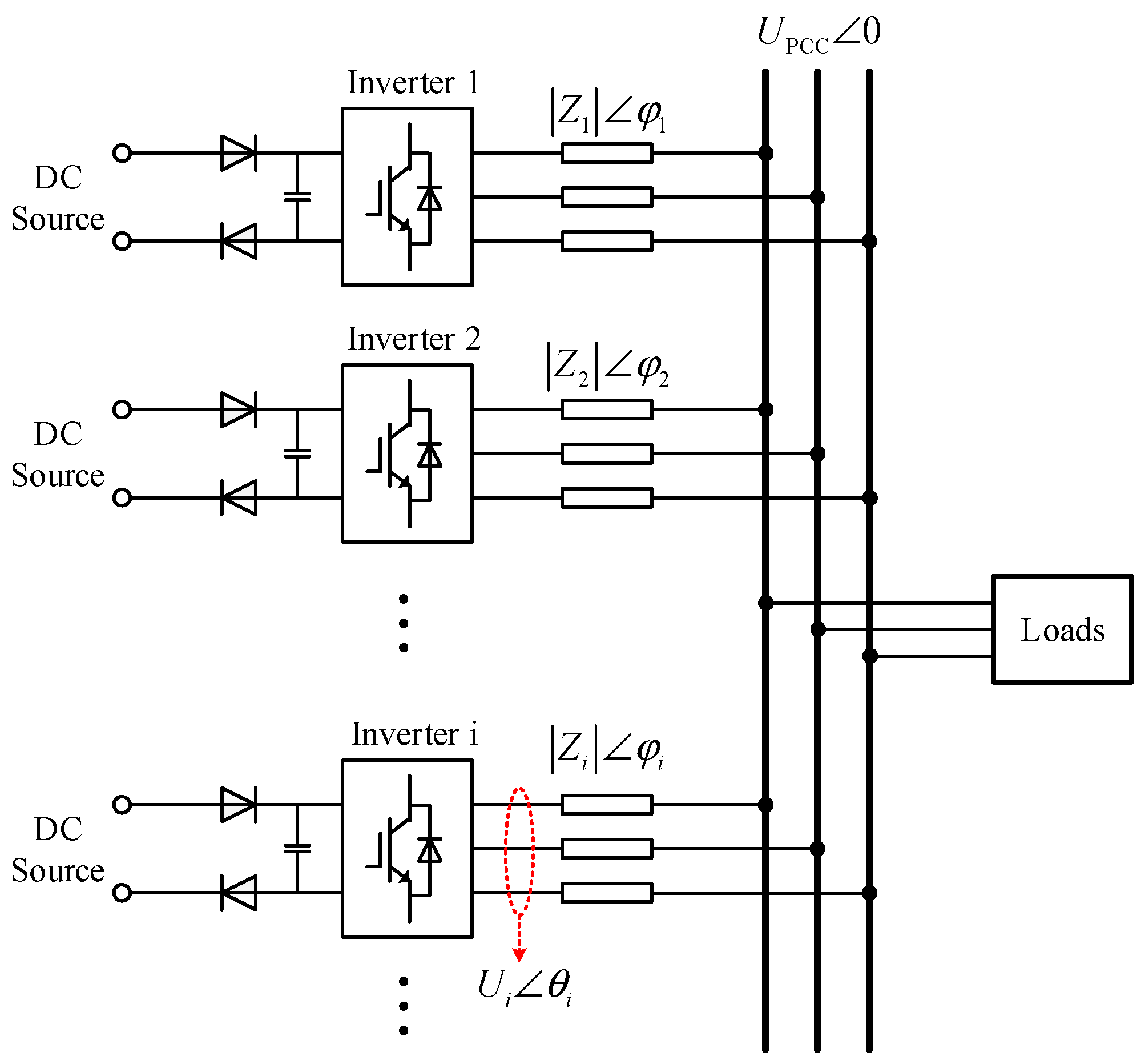
2.1. Power Circulation Analysis Based on the General Parallel Model

The mechanism underlying power circulation formation must be examined to mitigate the parallel transient circulation of inverters effectively. Figure 1 illustrates an equivalent circuit model depicting multiple inverters operating in parallel according to the characteristics of inverter output ports.
The active power output of inverter i (INV i) is calculated as follows:
P i = U i 2 cos φ i U i U PCC cos θ i + φ i Z i
Equation (1) ensures a non-negative active power of INV i by adjusting the output voltage’s amplitude and phase. A larger amplitude and leading phase maintain a positive active power output, thus preventing DC bus voltage pumping. However, in a scenario where multiple inverters coexist within MGs, substantial adjustments in the output voltage amplitude and phase of one inverter can induce DC bus voltage pumping in other inverters, leading to system instability. Hence, suppression control should focus on controlling the active power output of an inverter while considering its overall effect on the MG.
Although communication-based methods can effectively suppress DC bus voltage pumping and balance between inverters, they may compromise system reliability and thus communication quality. Thus, a non-communication-based control strategy is needed to suppress power circulation and facilitate the seamless transition from parallel transience to inverter stability. This section explains the parallel process by modeling two parallel inverters; their equivalent model is depicted in Figure 2.
Where U 1 θ 1 and U 2 θ 2 are the output voltages of INV 1 and INV 2, respectively; Z 1 φ 1 and Z 2 φ 2 are the line impedances of INV 1 and INV 2, respectively; and Z L φ L is the load impedance.
According to Kirchhoff’s voltage and current laws, the system of equations is as follows:
U 1 θ 1 = I ˙ 1 Z 1 φ 1 + I ˙ 1 + I ˙ 2 Z L φ L U 2 θ 2 = I ˙ 2 Z 2 φ 2 + I ˙ 1 + I ˙ 2 Z L φ L
The active power outputs of the two inverters are calculated as follows:
P 1 = U 1 Z D e n U 1 k 2 + 1 k 2 cos φ 1 + 2 U 1 cos φ 1 cos φ 2 φ L +                     U 1 1 k 1 cos φ 2 + k 2 k 1 c o s φ L U 2 cos Δ θ + φ 1 + φ 2 φ L                     U 2 1 k 2 cos Δ θ + φ 1 + 1 k 1 cos Δ θ + φ 2 P 2 = U 2 Z D e n U 2 k 1 + 1 k 1 cos φ 2 + 2 U 2 cos φ 2 cos φ 1 φ L +                     U 2 1 k 2 cos φ 1 + k 1 k 2 cos φ L U 1 cos Δ θ + φ 1 + φ 2 φ L                     U 1 1 k 1 cos Δ θ + φ 2 + 1 k 2 cos Δ θ + φ 1
where the following applies:
Z D e n = Z 1 Z 2 Z L + Z 1 Z L Z 2 + Z 2 Z L Z 1 +                             2 Z 1 cos φ 2 φ L + Z 2 cos φ 1 φ L + Z L cos φ 1 φ 2 Δ θ = θ 1 θ 2 k 1 = Z 1 Z L k 2 = Z 2 Z L
The voltage ratio and phase angle diagram derived from (3) when both inverters have positive active power outputs are depicted in Figure 3. Here, the line impedance of INV 1 is inductive, that of INV 2 is resistive, and the impedance angle of the load is determined based on the minimum value attained when the active power output of both inverters exceeds zero.
In the left panel of Figure 3, both inverters exhibit positive active power outputs in the region between the two surfaces. Regardless of the phase angle difference and load conditions, the local active power output can be kept positive by adjusting the output voltage amplitude or phase angle of the inverter. However, an extreme output voltage amplitude (too high or too low) can adversely affect the load operation or lead to irreversible damage. Thus, the output voltage is confined within a narrow range. In case of a significant initial phase difference, the inverter’s output voltage phase, not merely its amplitude, should be precisely adjusted to ensure a positive active power output. Additionally, the area between the two surfaces is depicted in Figure 3 (derived from the disparity between the outputs of the two inverters in regions P 1 = 0 and P 2 = 0 ). Furthermore, it illustrates that being light loaded ( Z L = 0 : short circuit; Z L + : unloaded) constrains the permissible range for adjusting the output voltage amplitude and phase, thereby complicating control efforts.

2.2. Analysis of Power Circulation of Parallel Inverters under Unloaded Condition

When the output of the inverter parallel system is unloaded ( Z L + ), Equation (3) is updated as follows:
P 1 Z L + = lim Z L P 1 = U 1 2 Z 1 cos φ 1 + Z 2 cos φ 2 Z 1 2 + Z 2 2 + 2 Z 1 Z 2 cos φ 1 φ 2                                                                                       U 1 U 2 Z 1 cos φ 1 + Δ θ + Z 2 cos φ 2 + Δ θ Z 1 2 + Z 2 2 + 2 Z 1 Z 2 cos φ 1 φ 2 P 2 Z L + = lim Z L P 2 = U 2 2 Z 2 cos φ 2 + Z 1 cos φ 1 Z 1 2 + Z 2 2 + 2 Z 1 Z 2 cos φ 2 φ 1                                                                                       U 1 U 2 Z 1 cos φ 1 Δ θ + Z 2 cos φ 2 Δ θ Z 1 2 + Z 2 2 + 2 Z 1 Z 2 cos φ 2 φ 1
For any given values of Z 1 , Z 2 , φ 1 , φ 2 , and φ L , the amplitude and phase angle of the inverter output voltage can be controlled to achieve P 1 Z L + 0 and P 2 Z L + 0 , which is expressed as follows:
U 1 2 Z 1 cos φ 1 + Z 2 cos φ 2 U 1 U 2 Z 1 cos φ 1 + Δ θ + Z 2 cos φ 2 + Δ θ 0 U 2 2 Z 2 cos φ 2 + Z 1 cos φ 1 U 1 U 2 Z 1 cos φ 1 Δ θ + Z 2 cos φ 2 Δ θ 0
Based on the given information and context, the range of each variable in Equation (6) is obtained as follows:
Δ θ θ max Z 1 > 0 Z 2 > 0 Z L 0 0 φ 1 π / 2 0 φ 2 π / 2 0 φ L π / 2 U min < U 1 < U max U min < U 2 < U max
where θ max is the maximum phase angle deviation of the inverter and U min , U max are the minimum and maximum output voltages of the inverter, respectively.
When Z 1 , Z 2 , φ 1 , φ 2 , φ L , U 1 , U 2 , and Δ θ satisfy the conditions of Equations (6) and (7), calculations using the software Lingo (18.0) demonstrate that the formulas in Equation (3) yield non-negative results. Hence, within the same range of voltage and phase angle deviation, the active power outputs of the two inverters can remain positive under unloaded conditions, so their active power outputs will be positive under other load conditions. An unloaded parallel model is used here instead of a full-load model to simplify the analysis. The line impedance is thus reformulated as follows:
Z L i n e φ L i n e = Z 1 φ 1 + Z 2 φ 2
Through the combination of Equations (8) and (5), the active power outputs of the two inverters are simplified as follows:
P 1 = U 1 Z L i n e U 1 cos φ L i n e U 2 cos φ L i n e + Δ θ P 2 = U 2 Z L i n e U 2 cos φ L i n e U 1 cos φ L i n e Δ θ
Similarly, the reactive power outputs of both inverters can be determined, although the specific calculation process is not elaborated in this paper.
Q 1 = U 1 Z L i n e U 1 sin φ L i n e U 2 sin φ L i n e + Δ θ Q 2 = U 2 Z L i n e U 2 sin φ L i n e U 1 sin φ L i n e Δ θ

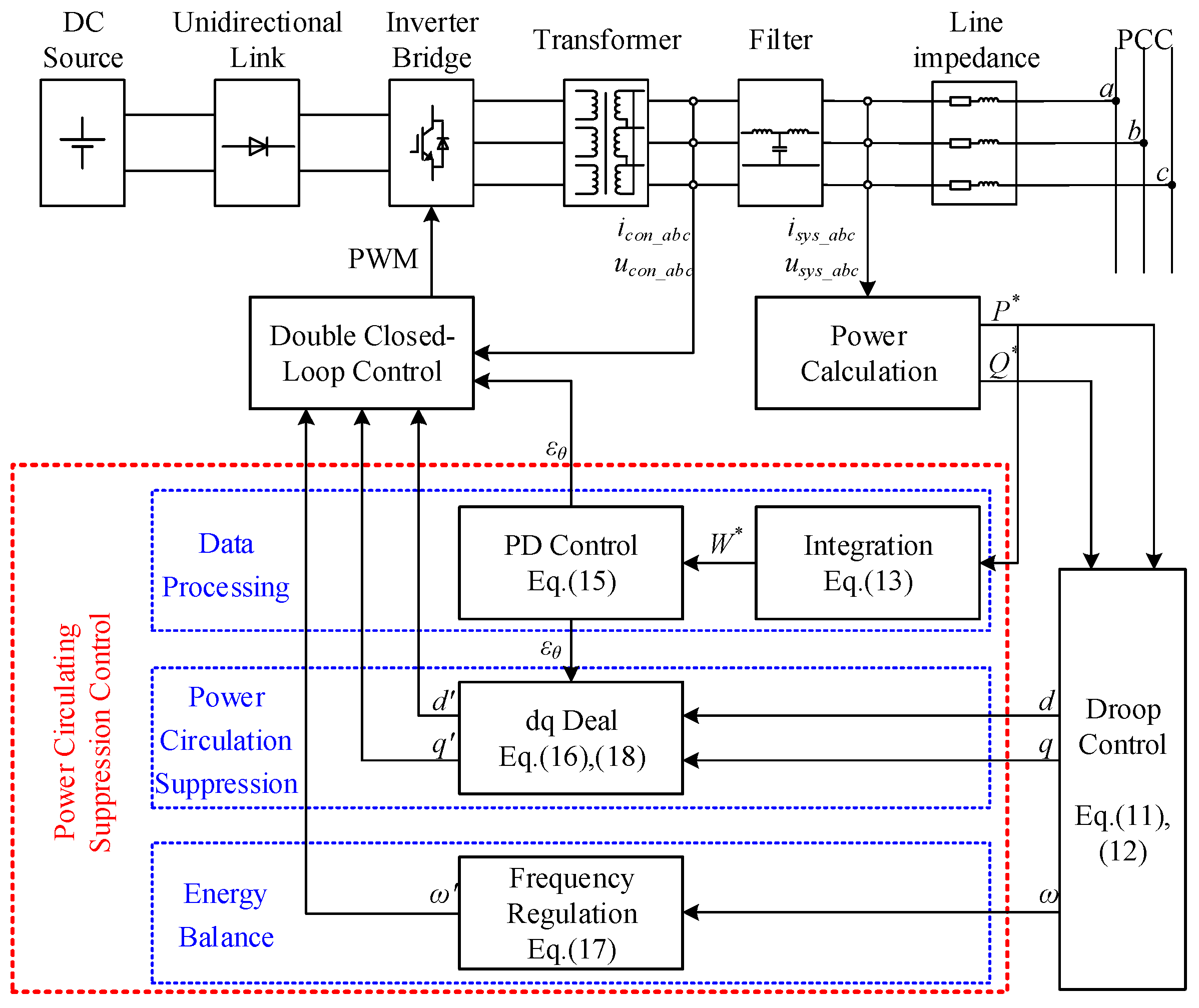
3. Control Strategy for Suppressing Power Circulation in Parallel Transients

The analysis demonstrates that adjusting the amplitude and phase angle of the inverter output voltage can generate a positive active power output. However, the adjustment range of the output voltage amplitude is constrained by the inverter’s performance index and load requirements. Additionally, the phase angle of the inverter’s output voltage is a dynamic parameter. The phase angle differences between inverters primarily impacts the system, with each inverter making incremental adjustments within a specific range, thereby ensuring minimal impact on system safety and stability. Therefore, fine-tuning the phase angles of the inverters helps minimize disruptions to system stability.
This section introduces the proposed control strategy, which suppresses power circulating currents by modifying the output voltage phase angle to address the power circulation issue. This strategy integrates conventional droop control with a power circulation suppression mechanism based on local information. Given the uncertainty of line impedance, the active and reactive power outputs are closely related to the output voltage and phase. The control equation [26] is implemented to optimize droop control as follows:
ω i = ω 0 k P ω P i * + k Q ω Q i *
U i = U 0 k P U P i * k Q U Q i *
where P i * and Q i * are the active and reactive power p.u. values of INV i, respectively; ω 0 is the normalized output radian frequency; U 0 is the normalized output voltage; and k P ω , k Q ω , k P U , and k Q U are the active power–frequency, reactive power–frequency, active power–voltage, and reactive power–voltage coefficients, respectively.
The suppression of power circulation comprises three key components: data processing, power circulation suppression, and energy balance. Each component is thoroughly examined and analyzed in the following sections for a comprehensive understanding of the power circulation suppression mechanism.

3.1. Data Processing

When the DC input has a unidirectional link, permitting active power transmission in only one direction, the active energy stored by INV i in the DC capacitor is influenced not only by the current active power output of the inverter but also by the energy stored in the DC capacitor at the previous time step. Considering the efficiency of the inverter ( η i ), the energy accumulated in the DC capacitor post-moment Δ t ( Δ t 0 ) is calculated as follows:
W i * t 0 + Δ t = max W i * t 0 t 0 t 0 + Δ t P i * v d v 1 η t 0 t 0 + Δ t S i * v d v , 0
where the following applies:
S i * t = P i * t 2 + Q i * t 2
X t is the value of X at moment t , explicitly capturing the value of X at that particular moment only.
Based on the calculated accumulated energy W i * t , the output phase angle of the inverter is adjusted to suppress power circulation.

3.2. Power Circulation Suppression

After the change in the bus voltage is determined, the rotation angle ε θ i is calculated using proportional–derivative (PD) control to suppress DC circulating currents.
ε θ i t = k P W i * t k D P i * t u W i * t
where k P and k D are the proportional and differential coefficients, respectively, subjected to PD control: u x = 1               x 0 0               x < 0 .
And d q is rotated according to the calculated angle.
d i t = d i t cos ε θ i t q i t sin ε θ i t q i t = d i t sin ε θ i t + q i t cos ε θ i t
Furthermore, control decoupling is achieved to mitigate the influence of reactive power on circulation suppression during regulation. In scenarios with negative power, the output voltage amplitude is maintained to ensure that the active power output remains positive. The voltage droop formula (Equation (12)) is integrated with the energy stored on the DC side (Equation (13)), and the output voltage amplitude is calculated as follows:
U i t = U i t s                                                                             ,   W i * t > 0 U 0 k P U P i * t k Q U Q i * t     ,   W i * t 0
where the following applies:
t s = t       ,     P i * t 0 t s   ,     P i * t < 0

3.3. Energy Balance

Conventional droop control can effectively suppress circulation by leveraging the power circulation component, which mitigates the undesirable phenomenon of voltage pumping in the DC bus. Nonetheless, during stable operation of the parallel system, each inverter may exhibit different DC bus voltages. Moreover, discrete control is susceptible to jitter near zero active power, leading to a gradual rise in the DC bus voltage until protection mechanisms are triggered, particularly under light load or unloaded conditions. Hence, upon accomplishing the suppression of the circulating current, it becomes imperative to balance the DC-side energy across each inverter further, thereby maintaining a relatively equitable operational state for all inverters. Therefore, the accumulated energy on the DC side is incorporated into the frequency droop equation, granting the inverter a higher DC bus voltage and a slightly accelerated radian frequency. This intentional phase angle shift expedites the release of functional quantities, ultimately facilitating the equilibrium of energy on the DC side among inverters. And Equation (11) is updated as follows:
ω i t = ω i t + k ω W i * t = ω 0 t k P ω P i * t + k Q ω Q i * t + k ω W i * t
where k ω is the radian frequency correction coefficient.
A control block diagram of the suppression strategy is derived, as shown in Figure 4.

4. Stability Assessment Based on Lyapunov Function Method

It is essential to note that this control strategy is built upon the foundation of conventional droop control when analyzing the system’s stability. The analysis focuses on stability under instantaneous phase angle compensation. An analysis of the control process shows that four distinct control states may manifest when two inverters are interconnected in parallel:
(1)
W 1 * t > 0 and W 2 * t > 0 ;
(2)
W 1 * t > 0 and W 2 * t = 0 ;
(3)
W 1 * t = 0 and W 2 * t > 0 ;
(4)
W 1 * t = 0 and W 2 * t = 0 .
Control state 4 exclusively emerges during the parallel moment (or stabilization), when the inverters are connected in parallel. The proposed suppression control strategy does not intervene in this state, as it aligns with conventional droop control. The proposed strategy is based on the stability of droop control, so the stability analysis for control state 4 is not further explored. The subsequent analysis concentrates on the system’s stability in control states 1 to 3, where the suppression control strategy is actively involved.
The suppression of DC bus voltage pumping in a parallel transient can be effectively modeled and analyzed by combining u x . According to the previous analysis, it is challenging to control the unloaded condition because there is no way to release the energy. Therefore, ideal inverters with η = 1 are used for the following analysis. Combined with Equation (13), the active power absorbed by the two inverters is derived as follows:
The inner phase angle deviation, frequency droop, and rotation angle primarily determine the phase angle difference between the two inverters. Equations (15) and (19) are combined to calculate the output phase angle deviation of the two inverters as follows:
Δ θ t = θ 1 t θ 2 t = Δ θ 1 P L L t 0 Δ θ 2 P L L t 0 +   0 t ω 1 v ω 2 v d v + ε θ 1 t ε θ 2 t
where θ 1 P L L t and θ 2 P L L t are the internal phases of the phase-locked loops (PLLs) of the two inverters.
The system state equation is derived as follows:
x ˙ = κ b κ c κ a κ c 1 0 x
where the following applies:
x = Δ θ ˙ Δ θ T κ a = u W 1 * t + u W 2 * t k ω u 0 2 sin φ L i n e κ b = u 0 2 2 k Q ω cos φ L i n e +                 u W 1 * t + u W 2 * t k P + 2 k P ω sin φ L i n e κ c = 2 k D u 0 2 sin φ L i n e + Z L i n e
The initial value of the state variable is determined using Equation (20).
Δ θ t 0 = k P W 1 * t 0 W 2 * t 0 + Δ θ P L L t 0 Z L i n e 2 k D u 0 2 sin φ L i n e + Z L i n e Δ θ ˙ t 0 = κ b k P W 1 * t 0 W 2 * t 0 + Δ θ P L L t 0 Z L i n e κ c 2 k D u 0 2 sin φ L i n e + Z L i n e
Equation (9) is combined with Equations (13)~(19) to approximate the deviation of the output phase angles of the two inverters as follows ( sin Δ θ t = Δ θ t , cos Δ θ t = 1 for Δ θ t 0 ):
Δ θ t = k P W 1 * t 0 W 2 * t 0 + Δ θ P L L t 0 κ c ϑ                                         ϑ cosh ϑ 2 κ c t κ b sinh ϑ 2 κ c t e κ b κ c t
where ϑ = κ b 2 4 κ a κ c .
The Lyapunov function V x , t is as follows:
V x , t = 1 2 Δ θ P L L t 2 = 1 2 Δ θ t ε θ 1 t ε θ 2 t 2
where Δ θ P L L t is a function of the continuous with respect to time.
The derivative of the Lyapunov function is obtained as follows:
V ˙ x , t = 2 U 0 2 Δ θ P L L t k P W 1 * t W 2 * t + Δ θ P L L t k Q ω cos φ L i n e + k P ω sin φ L i n e 2 k D u 0 2 sin φ + Z L i n e Z L i n e 2
Considering f t = k P W 1 * t W 2 * t + Δ θ P L L t , the sign of f t determines whether V ˙ x , t is positive or negative. Equation (9) is combined with Equations (19) and (20) to compute f t as follows:
f t = Δ θ t + 2 U 0 2 Z L i n e k D sin φ Δ θ t + k Q ω cos φ L i n e + k P ω sin φ L i n e 0 t Δ θ v d v
Considering W 1 * 0 = 0 and W 2 * 0 = 0 at the parallel moment, all variables from the previous moment are gradually adjusted (no sudden changes). Thus, the positive and negative characteristics remain consistent between f t and Δ θ t . The following is therefore deduced:
Δ θ t f t > 0 lim t + f t = 0   ,   t > 0
Hence, all derivatives of the Lyapunov function are negative.
V ˙ x , t t = t 0 < 0     ,     t 0 > 0
In summary, the constructed Lyapunov function demonstrates a decreasing trend, indicating a downward trajectory of the system’s energy and gradual stabilization. Stability is further validated in the subsequent simulations and experiments.

5. Simulation and Experiment

5.1. Simulation

The effectiveness of the proposed suppression control strategy is assessed by creating two parallel inverter models with a DC unidirectional link using Matlab/Simulink (R2022a). This study primarily focuses on mitigating circulating currents in a parallel steady state without a unidirectional link, with little emphasis on addressing the DC voltage pumping caused by DC-side energy accumulation. In this section, conventional droop control is applied for comparison. In a practical control scenario, the initial phase angle deviation is typically −2° to 2° due to filtering delays, PLL accuracy, and phase angle discrepancies in the line. However, a broader range of −6° to 6° is considered in this study. The rest of the simulation parameters are listed in Table 1.
The conditions of DC bus voltage pumping at various initial phase deviations and loads are observed for both the conventional droop control strategy and the proposed suppression control strategy, as illustrated in Figure 5.
Figure 5a shows that the DC bus voltage of the inverter operating under the conventional droop control strategy significantly increases during parallel transience. However, the maximum voltage surge diminishes with an increase in loads and a decrease in absolute phase deviations. Consequently, under conventional droop control, inverters with DC backstops can only be safely interconnected in parallel when the load is substantial and the phase deviation is small. Otherwise, the system’s operation safety and stability may be compromised. In Figure 5b, the impact of the suppression control strategy on parallel transient DC bus voltage pumping is depicted. The DC bus voltage remains controllable within 800 V across various loads and initial phase differences. It has an expanded operational envelope compared with that under conventional droop control. Thus, even in adverse scenarios of parallel connection, the inverter can effectively manage power circulation and the DC bus voltage, facilitating secure, stable parallel operation. An offline simulation is conducted to verify operational conditions 1, 2, and 3 to further validate this dynamic performance.
Stage 1 (parallel, unloaded): The control effect of the proposed suppression control strategy is further analyzed by conducting a simulation at a DC input voltage of 440 V and an initial phase deviation of 6° (the maximum deviation in the steady state and its control parameters are set according to this deviation value). The simulation waveform is shown in Figure 6. An analysis of the waveform in Figure 6 suggests that following the parallel connection of the two inverters for 0.5 s, the DC bus voltage of INV 2 rapidly surges to approximately 780 V, followed by a gradual decline toward stability. Subsequently, the DC bus voltages of both inverters slightly exceed the input DC voltages after stabilization, which is attributed to discrete control mechanisms and inherent control process delays. Furthermore, the Lyapunov function gradually decreases in the post parallel connection, indicating system stability. The two inverters approach stability by 3 s. Hence, under the proposed suppression control strategy, the two inverters can swiftly adjust the port characteristics to suppress power circulation, ensuring system operation stability.
Stage 2 (0.5 p.u. load increasing): As seen in Figure 7, at T 1 of the parallel connection, the two inverters are operating without any load. The initial phase angle deviates significantly, leading to pronounced power circulation and causing the DC bus voltage of INV 1 to surge. Subsequently, measures are implemented to suppress this surge, ensuring that the DC bus voltage remains below 800 V while the active power outputs of both inverters stabilize at approximately 0 p.u. Due to discrete control, the inverter outputs’ phase angle and voltage fluctuate near the equilibrium point, resulting in a frequent reactive power exchange between the two inverters. However, this reactive power exchange has little influence on the DC voltage because the periodic average value of the reactive power is zero. When the load increases to 0.5 p.u. at T 2 , although the DC bus voltage is near the DC input voltage, the substantial phase angle deviation between the two inverters prompts the inverter with the lagging phase angle to alternate between conventional droop control and power circulation suppression control. Consequently, the inverter handles most of the power distribution with a notably advanced phase angle during this period. At T 3 , the active power outputs of both inverters are subsequently adjusted according to the inverter power distribution strategy to achieve stability and power sharing between the two inverters. The Lyapunov function decreases throughout the parallel operation, signaling system stability. This trend becomes more pronounced post-loading, indicating enhanced system stability following the load increase. This finding is consistent with earlier analysis results indicating that control is more challenging under unloaded conditions.
Stage 3 (0.5 p.u. load shedding): As shown in Figure 8, two inverters are operating in parallel under a 0.5 p.u. load at T 4 . Initially, during the parallel transience, the active power of INV 1 becomes negative, causing DC bus voltage pumping. Thus, significant phase angle discrepancies can trigger power circulation, even under heavy loads, consistent with the findings in Figure 5. However, compared with the results for the unloaded parallel connection in Figure 6, the peak bus voltage here is lower, indicating a higher likelihood of power circulation under light or unloaded conditions. Throughout the adjustment process, INV 2 maintains a non-negative active power output. In this phase, the load power is mainly supplied by INV 1; this behavior aligns with observations during sudden load additions. As the system transitions from the 0.5 p.u. load to the unloaded condition at T 5 , INV 1 feeds active energy into INV 2, leading to a rise in the DC bus voltage. The system then maintains dynamic stability within a narrow range without load, with both inverters sustaining non-negative active power outputs. The decrease in the Lyapunov function throughout the parallel process indicates system stability. Hence, the system effectively manages the power exchange and maintains equilibrium between the inverters, leading to a stable operation despite the dynamic changes in load and power circulation.

5.2. Experiment

A prototype of two converters in parallel is built for experiments to verify the effectiveness of the proposed strategy, as shown in Figure 9.
The efficacy of the proposed strategy is further validated by constructing an experiment platform and confirming its static performance. The parameters of the platform are detailed in Table 1.
Stage 1 (parallel, unloaded, Figure 10): During the moment of parallel connection, both inverters exhibit significant power circulation. Initially, the DC bus voltage of INV 2 rapidly increases to 583 V before gradually decreasing as the energy is dissipated. Current monitoring reveals that after the parallel connection, the inverters stabilize after approximately 1 s of regulation. Although stability is achieved, variations in parameters between the inverters and the use of discrete control lead to an ongoing power exchange, causing slight fluctuations in the bus voltages of both inverters. The current in the unloaded parallel connection exceeds zero, and INV 2 exhibits a negative active power balance, but the DC bus voltage remains constant. This phenomenon arises from the challenge of consuming energy under unloaded conditions, necessitating energy dissipation through system losses via reactive power.
Stage 2 (0.5 p.u. load increasing, Figure 11): When a 0.5 p.u. load is added, the DC bus voltage changes slightly, which aligns with expectations for a parallel connection under unloaded conditions. Output current monitoring shows that most of the output power is supplied by INV 1 following the sudden load increase, gradually stabilizing over time. These observations are consistent with the simulation results.
Stage 3 (0.5 p.u. load shedding, Figure 12): The two inverters exhibit high-power AC operation under 0.5 p.u. load shedding, with the instantaneous port current reaching approximately 1.1 p.u. In this scenario, the DC bus voltage of INV 2 rises as it absorbs active power, followed by a subsequent increase in the DC bus voltage of INV 1 due to the closed-loop control. System stability is achieved through two adjustments within 1 s, aligning with the offline simulation results.

6. Conclusions

Power circulation may manifest during the transient operation of parallel inverters. The unidirectional energy flow characteristics of a DC unidirectional link can induce DC bus voltage pumping in the presence of power circulation. It may trigger system protection shutdown and significantly affect the overall stability of the power supply system. This study presents a control strategy based on local information to address this issue. This study proposed a novel approach leveraging locally absorbed energy as a feedback metric to adjust the inverter’s output voltage phase, mitigating circulating currents, which diverges from conventional parallel control methodologies. Concurrently, the DC side voltage equilibrium among inverters is methodically achieved through modulation of the output frequency. Moreover, the system’s stability under the proposed strategy is analyzed using the Lyapunov function method, demonstrating the asymptotical stability of the system. Simulations and experiments confirm that the proposed suppression strategy can effectively suppress power circulation. The proposed strategy can regulate and stabilize the DC bus voltage below 700 V within a 1 s adjusting process when the inverters parallel with unloaded, demonstrating commendable dynamic and static capabilities. While the strategy predicated on the instantaneous rectification of the phase angle is convenient to realize, the inverter’s efficiency must be procured through empirical measurement, which is necessary to calculate the absorption energy. Future research will consider the DC bus voltage to refine and assess the inverter’s absorbed energy via data fusion techniques.

Author Contributions

Conceptualization, S.J. and G.J.; Methodology, S.J. and J.Y.; Software, S.J.; Validation, G.J.; Formal analysis, F.X.; Investigation, S.J.; Resources, F.X.; Data curation, G.J.; Writing—original draft, S.J.; Writing—review & editing, S.G. and J.Y.; Visualization, S.G.; Supervision, G.J. and S.G.; Project administration, F.X. All authors have read and agreed to the published version of the manuscript.

Funding

This research was supported by National KeyLaboratory of Electromagnetic Energy.

Data Availability Statement

The data presented in this study are available on request from the corresponding authors.

Conflicts of Interest

The authors declare no conflict of interest.

References

  1. Hatziargyriou, N.; Asano, H.; Iravani, R.; Marnay, C. Microgrids. IEEE Power Energy Mag. 2007, 5, 78–94. [Google Scholar] [CrossRef]
  2. Parhizi, S.; Lotfi, H.; Khodaei, A.; Bahramirad, S. State of the art in research on microgrids: A review. IEEE Access 2015, 3, 890–925. [Google Scholar] [CrossRef]
  3. Rosero, C.X.; Velasco, M.; Marti, P.; Camacho, A.; Miret, J.; Castilla, M. Active power sharing and frequency regulation in droop-free control for islanded microgrids under electrical and communication failures. IEEE Trans. Ind. Electron. 2020, 67, 6461–6472. [Google Scholar] [CrossRef]
  4. Chandorkar, M.C.; Divan, D.M. Decentralized operation of distributed UPS systems. In Proceedings of the International Conference on Power Electronics, Drives and Energy Systems for Industrial Growth, New Delhi, India, 8–11 January 1996; pp. 565–571. [Google Scholar]
  5. Katiraei, F.; Iravani, M.R. Power management strategies for a microgrid with multiple distributed generation units. IEEE Trans. Power Syst. 2006, 21, 1821–1831. [Google Scholar] [CrossRef]
  6. Olivares, D.E.; Ali, M.S.; Etemadi, A.H.; Canizares, C.A.; Iravani, R.; Kazerani, M.; Hajimiragha, A.H.; Gomis-Bellmunt, O.; Saeedifard, M.; Palma-Behnke, R.; et al. Trends in microgrid control. IEEE Trans. Smart Grid 2014, 5, 1905–1919. [Google Scholar] [CrossRef]
  7. Fan, B.S.; Li, Q.K.; Wang, W.; Yao, G.Z.; Ma, H.H.; Zeng, X.J.; Guerrero, J.M. A novel droop control strategy of reactive power sharing based on adaptive virtual impedance in microgrids. IEEE Trans. Ind. Electron. 2022, 69, 11335–11347. [Google Scholar] [CrossRef]
  8. Zhang, H.; Li, Z.; Xue, Y.; Chang, X.; Su, J.; Wang, P.; Guo, Q.; Sun, H. A Stochastic Bi-level Optimal Allocation Approach of Intelligent Buildings Considering Energy Storage Sharing Services. IEEE Trans. Consum. Electron. 2024, 1–13. [Google Scholar] [CrossRef]
  9. Pan, Y.W.; Sangwongwanich, A.; Yang, Y.H.; Blaabjerg, F. Distributed control of islanded series PV-battery-hybrid systems with low communication burden. IEEE Trans. Power Electron. 2021, 36, 10199–10213. [Google Scholar] [CrossRef]
  10. Mathew, R.; Rueda-Escobedo, J.G.; Schiffer, J. Robust design of phase-locked loops in grid-connected power converters. Eur. J. Control 2024, 101055. [Google Scholar] [CrossRef]
  11. Tang, A.; Shao, Y.; Huang, Y.; Xu, Q. A new topology of the distributed power flow controller and its electromagnetic transient characteristics. Electr. Power Syst. Res. 2018, 163, 280–287. [Google Scholar] [CrossRef]
  12. Mukhtar, N.M.; Lu, D.D.-C. A Bidirectional Two-Switch Flyback Converter With Cross-Coupled LCD Snubbers for Minimizing Circulating Current. IEEE Trans. Ind. Electron. 2019, 66, 5948–5957. [Google Scholar] [CrossRef]
  13. Wei, B.; Guerrero, J.M.; Vasquez, J.C.; Guo, X. A Circulating-Current Suppression Method for Parallel-Connected Voltage-Source Inverters With Common DC and AC Buses. IEEE Trans. Ind. Appl. 2017, 53, 3758–3769. [Google Scholar] [CrossRef]
  14. Ghanbari, N.; Bhattacharya, S. Adaptive Droop Control Method for Suppressing Circulating Currents in DC Microgrids. IEEE Open Access J. Power Energy 2020, 7, 100–110. [Google Scholar] [CrossRef]
  15. Rosero, C.X.; Gavilánez, M.; Mejía-Echeverría, C. Droop-Free Sliding-Mode Control for Active-Power Sharing and Frequency Regulation in Inverter-Based Islanded Microgrids. Energies 2023, 16, 6442. [Google Scholar] [CrossRef]
  16. Yang, T.; Liu, Y.; Li, H.; Chen, Y.; Pen, H. Cooperative voltage control in distribution networks considering multiple uncertainties in communication. Sustain. Energy Grids Netw. 2024, 39, 101459. [Google Scholar] [CrossRef]
  17. Saleh, M.; Esa, Y.; Hariri, M.E.; Mohamed, A. Impact of information and communication technology limitations on microgrid operation. Energies 2019, 12, 2926. [Google Scholar] [CrossRef]
  18. Cai, X.; Zhong, H.; Li, Y.; Liao, J.; Chen, X.; Nan, X.; Gao, B. An event-triggered quantization communication strategy for distributed optimal resource allocation. Syst. Control Lett. 2023, 180, 105619. [Google Scholar] [CrossRef]
  19. Kasis, A.; Monshizadeh, N.; Lestas, I. A distributed scheme for secondary frequency control with stability guarantees and optimal power allocation. Syst. Control Lett. 2020, 144, 104755. [Google Scholar] [CrossRef]
  20. Wang, X.; Zhong, Z.; Jiang, W.; Zhao, X. Consensus-based secondary frequency control for parallel virtual synchronous generators. Sustain. Energy Grids Netw. 2024, 38, 101341. [Google Scholar] [CrossRef]
  21. Nguyen, T.-T.; Yoo, H.-J.; Kim, H.-M.; Nguyen-Duc, H. Direct Phase Angle and Voltage Amplitude Model Predictive Control of a Power Converter for Microgrid Applications. Energies 2018, 11, 2254. [Google Scholar] [CrossRef]
  22. John, B.; Ghosh, A.; Zare, F. Load Sharing in Medium Voltage Islanded Microgrids With Advanced Angle Droop Control. IEEE Trans. Smart Grid 2018, 9, 6461–6469. [Google Scholar] [CrossRef]
  23. Chen, J.; Hou, S.; Li, X. Decentralized Circulating Currents Suppression for Paralleled Inverters in Microgrids Using Adaptive Virtual Inductances. Energies 2018, 11, 1725. [Google Scholar] [CrossRef]
  24. Nie, C.; Wang, Y.; Lei, W.; Li, T.; Yin, S. Modeling and Enhanced Error-Free Current Control Strategy for Inverter with Virtual Resistor Damping. Energies 2018, 11, 2499. [Google Scholar] [CrossRef]
  25. Li, Z.; Chan, K.W.; Hu, J.; Guerrero, J.M. Adaptive Droop Control Using Adaptive Virtual Impedance for Microgrids With Variable PV Outputs and Load Demands. IEEE Trans. Ind. Electron. 2021, 68, 9630–9640. [Google Scholar] [CrossRef]
  26. Han, Y.; Li, H.; Shen, P.; Coelho, E.A.A.; Guerrero, J.M. Review of active and reactive power sharing strategies in hierarchical controlled microgrids. IEEE Trans. Power Electron. 2017, 32, 2427–2451. [Google Scholar] [CrossRef]
Figure 1. Multiple inverters in parallel.
Energies 17 04368 g001
Figure 2. Two inverters in parallel.
Energies 17 04368 g002
Figure 3. Positive range of the output active power of two parallel inverters.
Energies 17 04368 g003
Figure 4. Control block diagram of power circulation suppression.
Energies 17 04368 g004
Figure 5. Maximum DC bus voltage pumping in parallel transients: (a) conventional droop control, (b) proposed suppression control.
Energies 17 04368 g005
Figure 6. Parallel waveform (unloaded) under suppression control strategy: (a) DC bus voltage and V x , t , (b) output power.
Energies 17 04368 g006
Figure 7. Waveform (increasing load) under suppression control strategy: (a) DC bus voltage and V x , t , (b) output power.
Energies 17 04368 g007
Figure 8. Waveform (load shedding) under suppression control strategy: (a) DC bus voltage and V x , t , (b) output power.
Energies 17 04368 g008
Figure 9. Photo of the experiment hardware setup.
Energies 17 04368 g009
Figure 10. Experiment (parallel, unloaded): (a) DC bus voltage, (b) output voltage Uab, (c) output current Ia, (d) output power.
Energies 17 04368 g010
Figure 11. Experiment (0.5 p.u. load increasing): (a) DC bus voltage, (b) output current Ia.
Energies 17 04368 g011
Figure 12. Experiment (0.5 p.u. load shedding): (a) DC bus voltage, (b) output current Ia.
Energies 17 04368 g012
Table 1. Simulation and experiment parameters.
ParameterSymbolValue
System parameter
Input DC Voltage U DC 440   V
DC capacity C DC 0 . 0032   F
Output voltage root mean square U 0 390   V
Output voltage radian frequency ω 0 100 π
Initial phase error Δ θ Simulation: 6 °
Experiment: Actual
1.0 p.u. load Z L 0.76 + j 0.57   Ω
0.8 + j 0.6   p . u .
Line impedance 1 Z 1 0.000779 + j 0.000105   p . u .
Line impedance 2 Z 2 0.00619 + j 0.00081   p . u .
Control parameter
Active power–frequency coefficient k P ω 0.1131   rad / s
Reactive power–frequency coefficient k Q ω 0.0192   rad / s
Active power–voltage coefficient k Q U 0 . 0032   p . u .
Reactive power–voltage coefficient k Q U 0 . 0020   p . u .
Radian frequency correction coefficient k ω 20   rad / s
Proportional coefficient k P 12.6288   rad / s
Differential coefficient k D 0 . 0454   rad
System efficiency η Simulation: 0.99
Experiment: 0.92
Stage
Stage 1 Parallel connection
Stage 2 0.5 p.u. load increasing
Stage 3 0.5 p.u. load shedding
Disclaimer/Publisher’s Note: The statements, opinions and data contained in all publications are solely those of the individual author(s) and contributor(s) and not of MDPI and/or the editor(s). MDPI and/or the editor(s) disclaim responsibility for any injury to people or property resulting from any ideas, methods, instructions or products referred to in the content.

