Article

Variable Delayed Time Control for Dual Three-Phase Permanent Magnet Synchronous Motor with Double Central Symmetry Space Vector Pulse Width Modulation

School of Electrical and Information Engineering, Jiangsu University, Zhenjiang 212013, China
*
Author to whom correspondence should be addressed.
Energies 2024, 17(17), 4347; https://doi.org/10.3390/en17174347
Submission received: 30 July 2024 / Revised: 26 August 2024 / Accepted: 28 August 2024 / Published: 30 August 2024

Abstract

To address the harmonic issues associated with the pulse width modulation (PWM) method, this article introduces variable delayed time (VDT) space vector pulse width modulation (SVPWM) with double central symmetry for dual three-phase permanent magnet synchronous machines (DTP-PMSMs). Firstly, the switching sequence of four traditional vectors undergoes double central symmetry, resulting in the doubling of the frequency of the phase voltage. This alteration eliminates harmonics occurring at odd multiples of carrier frequency. Additionally, the adopting of a single null vector minimizes the additional switching times introduced by the double central symmetry. Subsequently, VDT-SVPWM is employed to further suppress the harmonics at the even multiples of carrier frequency. The implementation of the proposed double central symmetry method involves directly utilizing the calculated duty cycle of the traditional four vectors. Moreover, integrating VDT-SVPWM with the double central symmetry method is straightforward. Simulation and experimental results validate the efficacy of the proposed method in suppressing harmonics and mitigating vibrations in the DTP-PMSM.

1. Introduction

The dual three-phase permanent magnet synchronous machine (DTP-PMSM) presents notable advantages in comparison to traditional three-phase PMSMs. These advantages include higher power density, diminished torque ripples, improved reliability, and expanded degrees of control freedom [1,2,3]. Due to these merits, the DTP-PMSM has received substantial research attention.
The space vector pulse width modulation (SVPWM) strategy is widely employed in both industrial and commercial applications owing to its numerous advantages. These include simple computation, a broad linear modulation range, and superior steady-state performance. Nevertheless, the use of the SVPWM method generates substantial amounts of high-frequency PWM harmonics at the carrier frequency and its multiples [4,5]. These concentrated harmonics contribute to the generation of stator magneto-motive force harmonics, which serve as the primary sources of radial magnetic forces. The significant amplitude of radial magnetic forces can lead to severe high-frequency vibrations [6,7,8].
The random PWM method mitigates high-frequency harmonics by introducing randomness into the carrier period or the width and position of the pulse sequence. This approach is extensively employed to alleviate high-frequency harmonics and vibration owing to its excellent performance [9,10,11]. Random PWMs can be categorized into random pulse positions and random carrier frequencies. Random pulse position methods reduce the amplitude of high-frequency harmonics by altering the executing time of zero vectors. So, the impact of random pulse positions largely depends on the zero-vector application time, which is greatly affected by the operating conditions of the motor [12]. Wang et al. [13] proposed an innovative random pulse position method that achieves pulse position randomization by employing N distinct carrier modes. This approach effectively eliminates high-frequency PWM harmonics, except for the N-order. However, this method involves more switching times when compared to the traditional SVPWM method.
The random carrier frequency method proves effective in significantly reducing the peak value of high-frequency harmonics, subsequently leading to a reduction in vibration and noise. Nonetheless, in the traditional random carrier frequency method, the random alteration of the sampling frequency poses challenges in calculating controller parameters and may lead to a degradation in steady-state performance [14,15]. Bu et al. [16] proposed a variable delayed time (VDT) SVPWM method, achieving carrier frequency randomization by altering the delayed time of the carrier period. Moreover, the sampling cycle was kept fixed to minimize the degradation of control performance. While increasing the spread spectrum range enhances the suppression of high-frequency harmonics and vibration, an excessively large spread spectrum range may introduce more PWM harmonics into the low-frequency band, potentially leading to resonance issues [17].
In addition to the spread spectrum modulation method, some approaches focus on altering the switching sequence to achieve reduced harmonics and vibrations. Ye et al. [18] proposed an innovative variable sequence PWM strategy to suppress high-frequency harmonics and current ripples. The current ripples were utilized to predict real-time trajectories and root mean square values of current harmonics. Huang et al. [19,20,21] proposed a novel SVPWM, aiming to eliminate the odd-order carrier frequency harmonics and vibrations. However, the rearrangement of the space vector order leads to increased switching losses. Moreover, the asymmetrical PWM generation mode results in the generation of low-frequency even-order fundamental harmonics. Consequently, based on the above analysis, the effectiveness of single sequence reconstruction in suppressing high-frequency harmonics is limited.
In this paper, an innovative dual centralization strategy is proposed, which can eliminate high-frequency harmonics at odd frequency multiples. By combining VDT-SVPWM, the problem that the harmonic peak value of traditional VDT-SVPWMs is still high at double the frequency is solved. In addition, by using a single zero vector to reduce the switching frequency, the distribution of high-frequency harmonics is further improved at a small cost, and the high-frequency vibration caused by high-frequency harmonics is effectively reduced.
The rest of this article is organized as follows. Section 2 introduces traditional SVPWM and variable delayed time method for the DTP-PMSM. Section 3 provides a detailed illustration and discussion of the proposed method. Experimental results are presented in Section 4. Finally, Section 5 concludes the article.

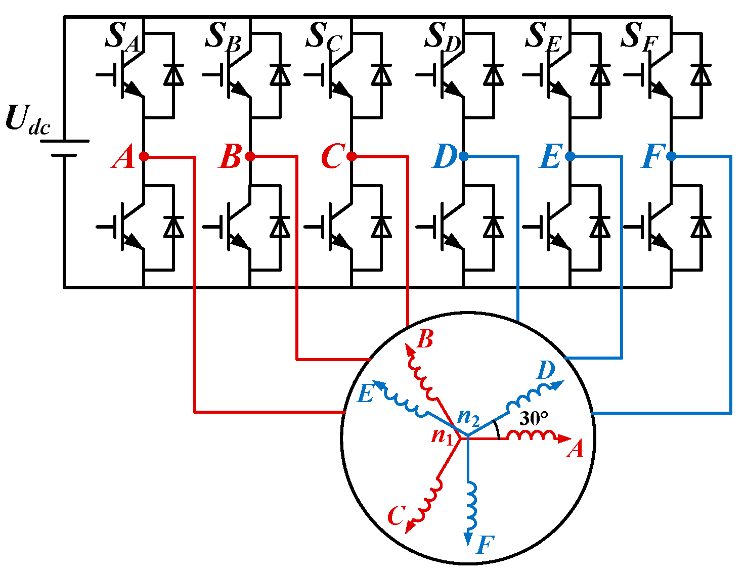
2. SVPWM for Dual-Three Phase Machine

Figure 1 depicts the schematic diagram of the DTP-PMSM drive system. According to the vector space decomposition principle, all variables of the DTP-PMSM can be transformed into three subspaces. These subspaces consist of the αβ subspace, z1z2 subspace, and o1o2 subspace.
In Figure 2, the distribution of 64 space voltage vectors in the αβ and z1z2 subspace is depicted. These two subspaces can be divided into twelve sectors. The sixty-four vectors are categorized into four groups based on their amplitudes, and those positioned at the outermost layer are referred to as big vectors. The PWM strategy utilizing four big vectors is a common approach employed by the DTP-PMSM, often appreciated for its merits of reduced harmonics and enhanced voltage utilization. The schematic diagrams of switching sequences and vector syntheses are given in Figure 3. The switching sequence of the four big vectors method is illustrated in Figure 3a. To facilitate implementation, the switch sequences are often centralized, as depicted in Figure 3b.

3. Proposed Method

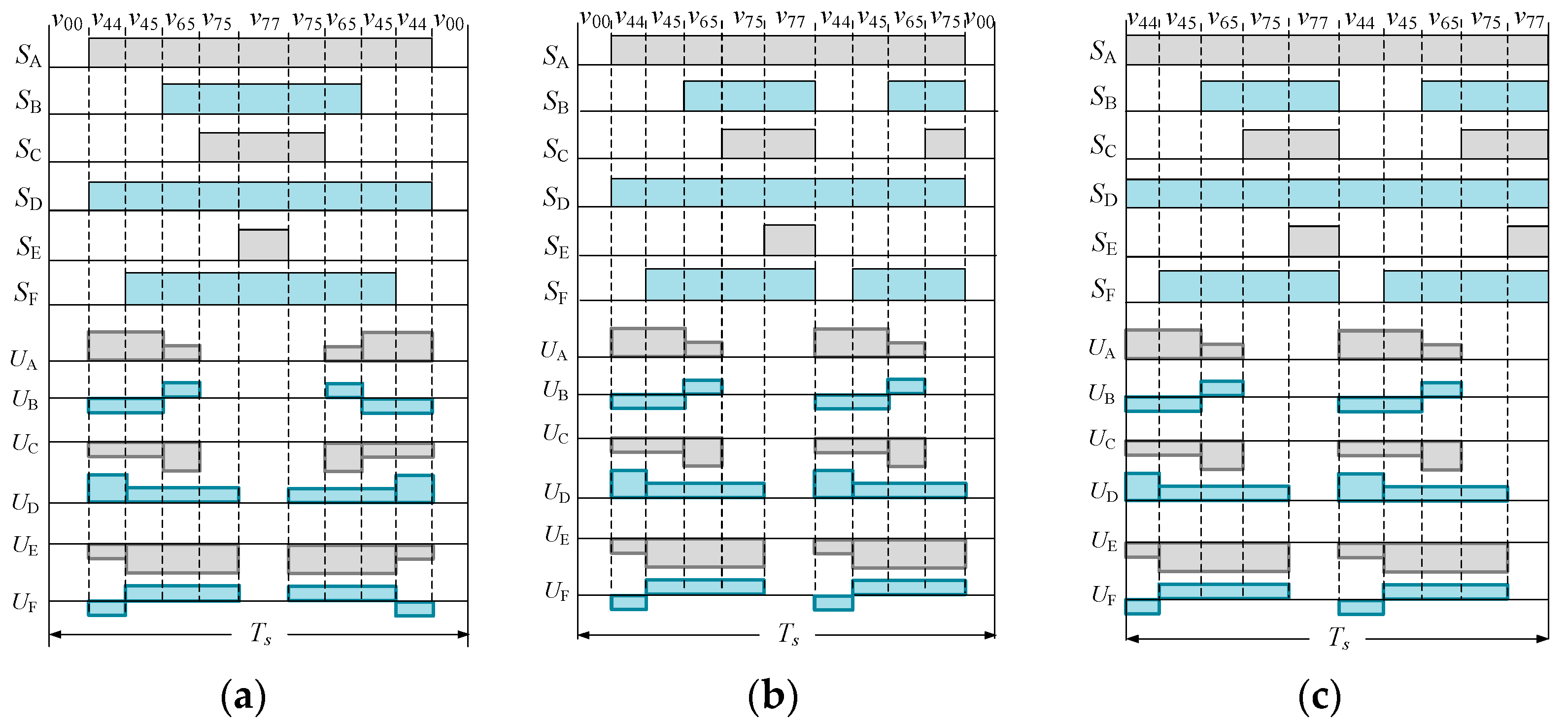
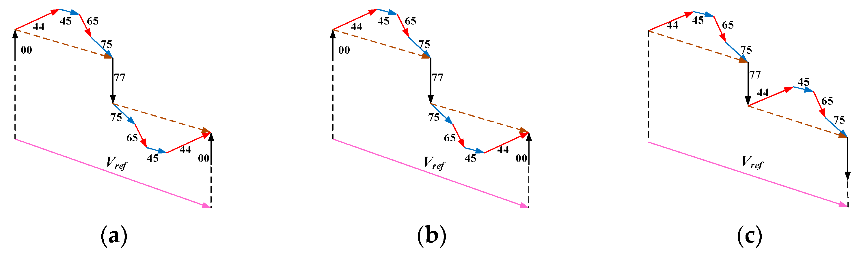
3.1. Sequence Rearrangement for Harmonic Elimination

The traditional SVPWM using four vectors after central symmetry is illustrated in Figure 4a. Throughout the first half cycle, the sequence of the active voltage vectors in the initial half of the carrier period is v44, v45, v65, v75. In the second half of the carrier period, the order is v75, v65, v45, v44. So, the output voltage in the first half and the second half of the carrier wave is mirror symmetric. As shown in Figure 4b, by rearranging the order of the voltage vectors in the second half of the carrier period, the sequence of the voltage vectors becomes v44, v45, v65, v75. So, the phase voltage in the second half period becomes identical to that in the first half. However, as illustrated in Figure 4b, the rearrangement of voltage vectors leads to an increase in switching times within one carrier period. The average switching time in one carrier period of the traditional SVPWM are six. In Figure 4b, the number of switching times increased to nine. In the traditional SVPWM method, there are typically two null vectors, namely v00 and v77. The choice of the null vector depends on the sector of the reference voltage. In Sectors I, II, V, VI, IX, and X, v77 is selected. In Sectors III, IV, VII, VIII, XI, and XII, v00 is selected. As shown in Figure 4c, using a single null vector can reduce the additional switching times in one carrier period to eight. Hence, the frequency of the phase voltage within a single carrier period can be increased without altering the carrier cycle. In this scenario, the formulation of the phase voltage within a single carrier period can be derived as follows:
f ( t + 0.5 T s ) = f ( t ) ,
where Ts is the carrier period. Then, the frequency of PWM harmonics can be obtained as follows:
m ω c = m 2 π 0.5 T s = 2 m ω s
where ωs is the carrier angular frequency. m represents the order of the carrier harmonic, whose value is a positive integer.
As expressed in (2), the high-frequency PWM harmonics are situated at 2s. Consequently, the high-frequency harmonics exclusively manifest at the even multiples of the carrier frequency. The schematic diagrams of vector synthesis for traditional SVPWM and asymmetrical SVPWM are depicted in Figure 5a, Figure 5b, and Figure 5c, respectively.

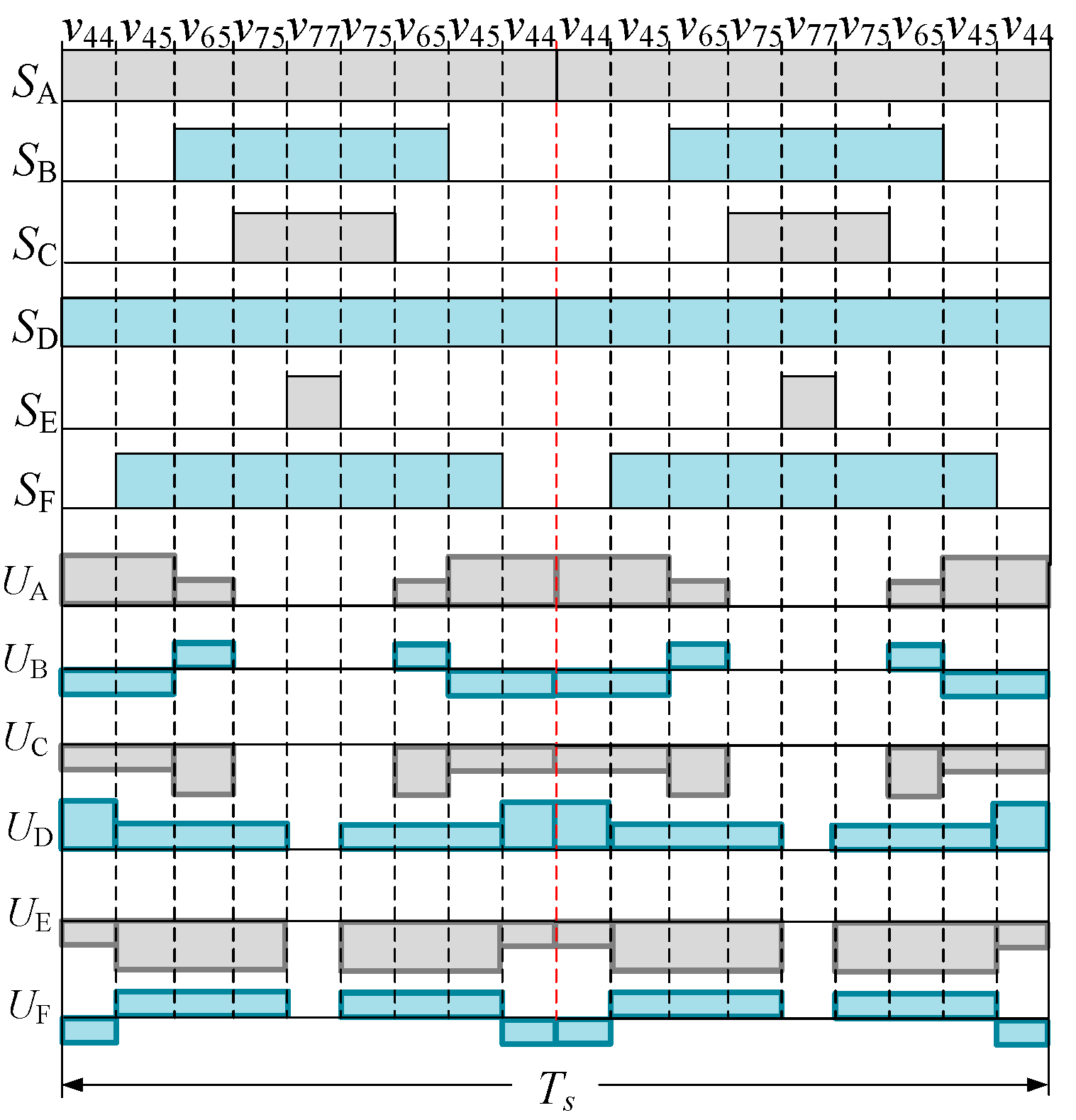
3.2. VDT-SVPWM with Double Central Symmetry

As depicted in Figure 4c, the asymmetrical switching sequence will introduce complexity in implementation. Additionally, the asymmetrical PWM waveform contributes to low-order fundamental frequency harmonics in the phase current [21]. To address the aforementioned challenges, this section introduces a double central symmetry approach.
Utilizing Figure 4c as a reference, the switching sequences can be centralized in the first and second, respectively, resulting in the double central symmetry SVPWM depicted in Figure 6. The vector synthesis of double central symmetry is illustrated in Figure 7. In the first half period, the sequence of applied vectors is v44-v45-v65-v75-v77-v75-v65-v45. This order is identical to that of the traditional SVPWM shown in Figure 3a but is applied twice in one control period. As shown in Figure 5, the switching sequence is symmetrical and the phase voltage in the second half period is the same as the that in the first period. This design can eliminate the high-frequency harmonics at the odd-order carrier frequency. Additionally, after rearranging the voltage vectors and selecting null vectors, the synthesized voltage vectors will not change. This means that the double central symmetry will not affect the control performance of the fundamental wave.
While the high-frequency harmonics can be eliminated by the proposed double central symmetry SVPWM method, the harmonics at even multiples of carrier frequency are preserved. To further mitigate high-frequency harmonics at even multiples of the carrier frequency, the double central symmetry is combined with VDT-SVPWM.
The time delayed for the subsequent carrier period can be computed during the current sampling period. The nth carrier period is expressed as (3), and the delayed time of the nth carrier period can be expressed as (4).
T sw ( n ) = T samp + Δ t n Δ t n 1
Δ t = R VDT T samp
where Tsamp is sampling period. RVDT is the random number whose range is in [0, 1]. Due to the existence of Δt, the actual output voltage is delayed by a period of time.

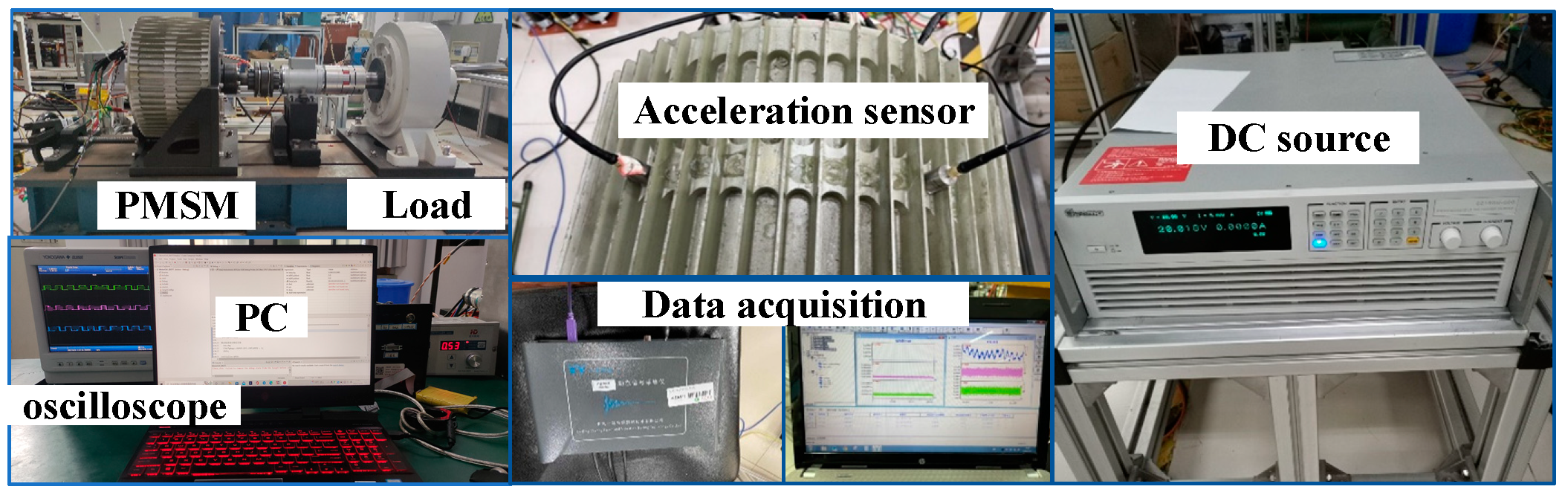
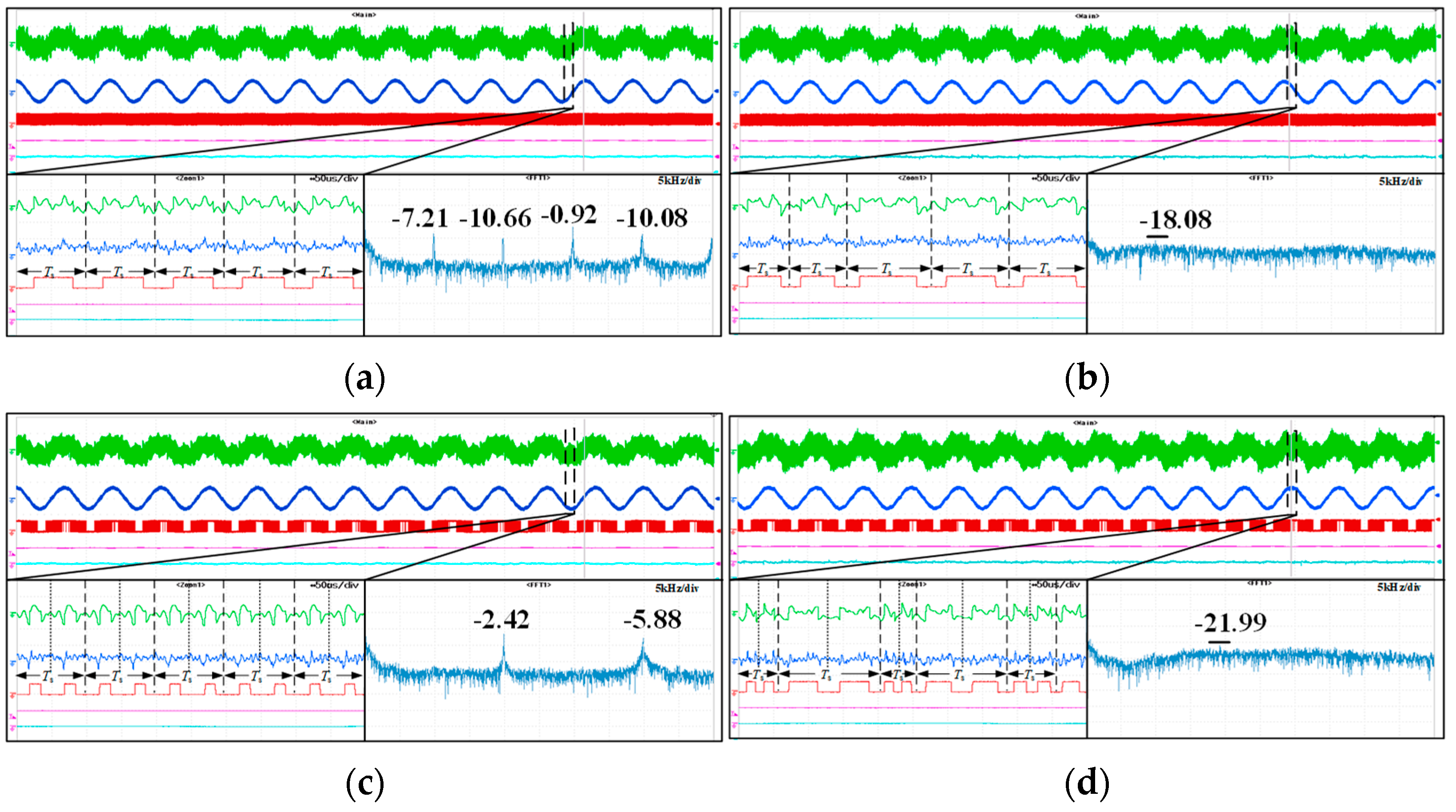
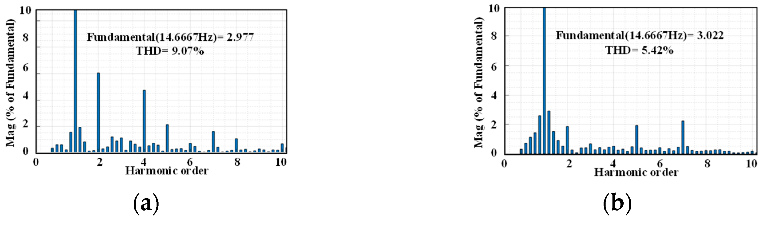
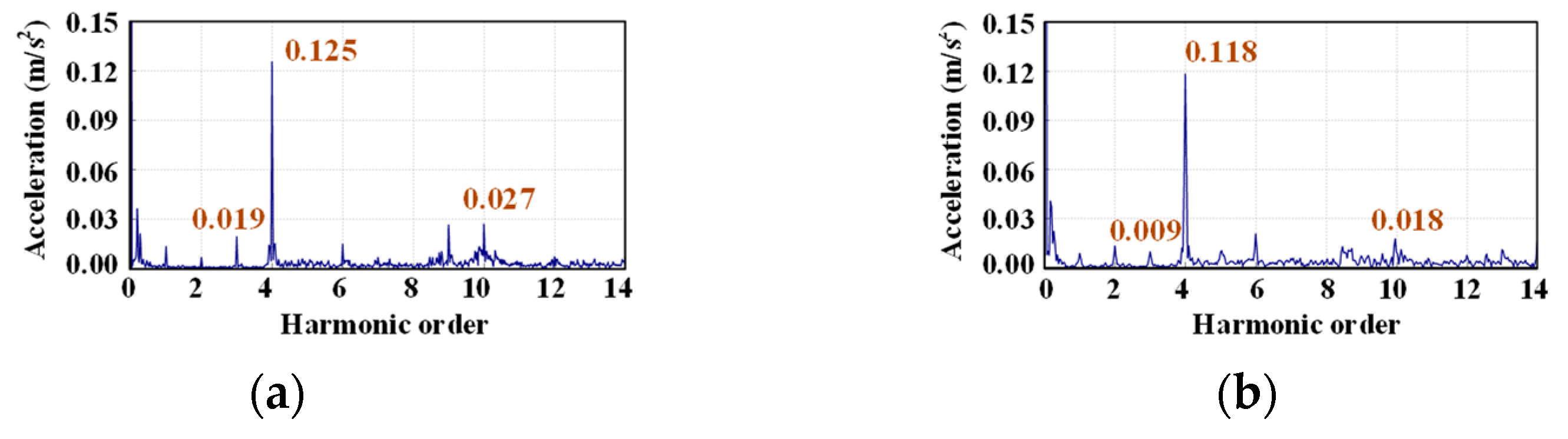
4. Experimental Verifications

To verify the effectiveness of the proposed method, a DTP-PMSM laboratory platform was established, as depicted in Figure 8. The platform comprises a DTP-PMSM, a magnetic power brake load, a DC source, and a six-phase two-level voltage-source inverter. Radial acceleration is measured by a YA1102ICP acceleration sensor (Beijing Yiyang Vibration Testing Technology Co., Ltd., Beijing, China). The experimental parameters of the motor are detailed in Table 1.
Figure 9 presents the results of different control strategies, including the phase voltage, the PWM waveform, the phase current, and its FFT of different control strategies. In Figure 9a, utilizing the traditional SVPWM method, the period of phase voltage and current is Ts. Also, there are fixed high-frequency PWM harmonics located at the carrier frequency and its multiples. In Figure 9b, the experimental results of the traditional VDT-SVPWM show the obvious suppression of PWM harmonic peaks, with a peak amplitude of −18.08 dB, located at 10 kHz. However, some high-frequency harmonic components intrude into the low-frequency band, increasing the risk of resonance. However, there are components of high-frequency harmonics that intrude to the low-frequency band, which increases the possibility of resonance. In Figure 9c, adopting the double central symmetry SVPWM method results in the period of the phase voltage and current being reduced to 0.5Ts. This allows the PWM harmonics frequency to increase to the doubled carrier frequency. Nearly all of the PWM harmonics at odd carrier frequency multiples can be eliminated. However, a slight increase in amplitude is observed at 20 kHz, measuring −2.42 dB. Figure 10d shows the experimental results of VDT-SVPWM with double central symmetry. The peak amplitude of PWM harmonics is −21.99 dB, located at the 20 kHz, which is then further suppressed. Moreover, the harmonics in the [5 kHz, 10 kHz] range are noticeably reduced.
Figure 10 presents the FFT analysis of vibration signals obtained through acceleration sensors. In Figure 10a, with the traditional SVPWM method, high-frequency vibrations are present at the carrier frequency and its multiples. When traditional VDT-SVPWM is applied, the high-frequency vibrations shown in Figure 10b are suppressed to a low level. However, a peak amplitude at the frequency of 10 kHz is observed. Moreover, due to the wide range of carrier frequency variation, numerous harmonics intrude into the [1 kHz, 10 kHz] range. In Figure 10c, with the use of double central symmetry SVPWM, the odd-order carrier frequency vibrations are eliminated. However, the vibrations at the even multiples of the carrier frequency are preserved. In the experimental results of VDT-SVPWM with double central symmetry, the high-frequency vibrations are suppressed to a lower level compared to that of traditional VDT-SVPWM. The peak amplitude of high-frequency harmonics is located at a higher frequency. Furthermore, vibrations in the [1 kHz, 10 kHz] range are not affected by VDT-SVPWM. In conclusion, VDT-SVPWM with the double central symmetry method exhibits superior performance in suppressing high-frequency vibrations.
To further validate the effectiveness of the proposed method, the spread factor is employed in this paper. The spread factor enables a quantitative analysis of the degree to which harmonics and vibrations spread. To precisely analyze the advantages of the proposed method, spread factors for different methods are calculated within the range of [1 kHz, 25 kHz]. The results of spread factors for various methods are presented in Table 2. Upon reviewing the results in Table 2, it is evident that the spread factors of the proposed method are the lowest. This signifies superior performance in effectively diffusing harmonics and vibrations across the middle- and high-frequency bands.
As discussed in Section 3, the utilization of asymmetrical PWM waveforms leads to the generation of low-frequency even-order fundamental harmonics. These harmonics will contribute to additional low-frequency vibrations. Figure 11 illustrates the current FFT results of modified SVPWM under different PWM generation methods. In Figure 11a, when asymmetrical PWM is applied, the amplitudes of second-order and forth-order harmonics are 6.1% and 4.7%, respectively. In contrast, Figure 11b presents the experimental results of the symmetrical PWM generation method, where the amplitudes of second-order and forth-order harmonics are reduced to 1.8% and 0.7%, respectively. In Figure 12, the low-frequency vibration results of modified SVPWM under different PWM generation methods are illustrated. The highest amplitude in the low-frequency band is forth-order, which is determined by the pole slot fit of the motor. Additionally, Figure 12a demonstrates vibrations generated at the other frequency due to the use of the asymmetrical PWM generation method. In Figure 12b, when the symmetrical PWM generation method is employed, these unexpected vibrations are suppressed to a lower amplitude.

5. Conclusions

This paper introduces a combined approach of double central symmetry SVPWM with VDT-SVPWM for DTP-PMSMs. Experimental results on PWM waveforms, line voltage, phase current, and vibrations are presented. The experimental findings demonstrate that the proposed double central symmetry SVPWM method effectively eliminates odd-order high-frequency PWM harmonics and vibrations. When combined with the traditional VDT-SVPWM method, there is a noticeable suppression of high-frequency PWM harmonics and vibrations. Furthermore, through the analysis of spread factors across different methods, the proposed approach demonstrates superior performance in suppressing high-frequency harmonics and vibrations. Additionally, compared with modified asymmetrical SVPWM, the proposed method exhibits superior performance in mitigating low-frequency harmonics and vibration. Moreover, the adoption of a symmetrical PWM generation mode is highlighted for its ease of implementation.

Author Contributions

Conceptualization, T.T. and S.L.; methodology, T.T.; software, S.L.; validation, T.T. and S.L.; formal analysis, T.T.; investigation, T.T.; resources, S.L.; data curation, T.T.; writing—original draft preparation, S.L.; writing—review and editing, T.T.; visualization, T.T.; supervision, T.T.; project administration, T.T.; funding acquisition, T.T. All authors have read and agreed to the published version of the manuscript.

Funding

This research was funded by the National Natural Science Foundation of China under Grants 52107047 and 52025073.

Data Availability Statement

The data are contained within the article.

Acknowledgments

Thanks to the School of Electrical and Information Engineering, Jiangsu University for their support.

Conflicts of Interest

The authors declare no conflict of interest.

References

  1. Ma, X.; Li, B.; Li, G.; Zhu, Q. An SVPWM strategy with extended linear modulation range for dual three-phase machine drives under unbalanced power sharing conditions. IEEE Trans. Power Electron. 2023, 38, 4527–4541. [Google Scholar] [CrossRef]
  2. Jin, L.; Mao, Y.; Wang, X.; Shi, P.; Lu, L.; Wang, Z. Optimization-based maximum-torque fault-tolerant control of dual three-phase PMSM drives under open-phase fault. IEEE Trans. Power Electron. 2023, 38, 4527–4541. [Google Scholar] [CrossRef]
  3. Song, Z.; Jia, Y.; Liu, C. Open-phase fault-tolerant control strategy for dual three-phase permanent magnet synchronous machines without controller reconfiguration and fault detection. IEEE Trans. Power Electron. 2023, 38, 789–802. [Google Scholar] [CrossRef]
  4. Acosta-Cambranis, F.; Zaragoza, J.; Berbel, N.; Capella, G.J.; Romeral, L. Constant common-mode voltage strategies using sigma–delta modulators in five-phase VSI. IEEE Trans. Ind. Electron. 2023, 70, 2189–2198. [Google Scholar] [CrossRef]
  5. Xu, D.; Yang, M.; Chen, Y.; Long, J.; Xu, D. EMI-regulated SiC-based motor drives with markov chain pseudo-random frequency space vector pulse width modulation strategy. IEEE Trans. Energy Convers. 2022, 37, 2348–2358. [Google Scholar] [CrossRef]
  6. Deng, W.; Huang, J.; Qian, Z.; Qian, C.; Zhong, D. A random pulse position-based selective noise cancellation modulation method for SVPWM driven PMSMs. IEEE Trans. Energy Convers. 2022, 37, 2190–2198. [Google Scholar] [CrossRef]
  7. Lee, K.; Shen, G.; Yao, W.; Lu, Z. Performance characterization of random pulse width modulation algorithms in industrial and commercial adjustable-speed drives. IEEE Trans. Ind. Appl. 2017, 53, 1078–1087. [Google Scholar] [CrossRef]
  8. Xie, Y.; Jiang, D.; Hu, F.; Liu, Z. Research on common mode EMI and its reduction for active magnetic bearings. IEEE Trans. Power Electron. 2023, 38, 4246–4250. [Google Scholar] [CrossRef]
  9. Schulz, S.E.; Kowalewski, D.L. Implementation of variable-delay random PWM for automotive applications. IEEE Trans. Veh. Technol. 2007, 56, 1427–1433. [Google Scholar] [CrossRef]
  10. Kirlin, R.L.; Bech, M.M.; Trzynadlowski, A.M. Analysis of power and power spectral density in PWM inverters with randomized switching frequency. IEEE Trans. Ind. Electron. 2002, 49, 486–499. [Google Scholar] [CrossRef]
  11. Trzynadlowski, A.M.; Kirlin, R.L.; Legowski, S.F. Space vector PWM technique with minimum switching losses and a variable pulse rate. IEEE Trans. Ind. Electron. 1997, 44, 173–181. [Google Scholar] [CrossRef]
  12. Dove, A.; Naudé, J.; Hofsajer, I. An argument for the relationship between spectral spreading and probability spreading for EMI-Reduction in DC–DC converter. IEEE Trans. Power Electron. 2022, 35, 1459–1472. [Google Scholar] [CrossRef]
  13. Bu, F.; Liu, Q.; Pu, T.; Zhao, Y.; Ma, B.; Ma, C.; Degano, M.; Gerada, C. Analysis and performance of five-phase piecewise-random-switching-frequency space vector pulse width modulation. IEEE Trans. Energy Convers. 2021, 36, 2339–2347. [Google Scholar] [CrossRef]
  14. Zhang, P.; Wang, S.; Li, Y. Performance and analysis of n-state random pulse position SVPWM with constant sampling frequency. IEEE Trans. Power Electron. 2022, 37, 13606–13625. [Google Scholar] [CrossRef]
  15. Lai, Y.; Chang, Y.; Chen, B. Novel random-switching PWM technique with constant sampling frequency and constant inductor average current for digitally controlled converter. IEEE Trans. Ind. Electron. 2013, 60, 3126–3135. [Google Scholar] [CrossRef]
  16. Bech, M.M.; Blaabjerg, F.; Pedersen, J.K. Random modulation techniques with fixed switching frequency for three-phase power converters. IEEE Trans. Power Electron. 2000, 15, 753–791. [Google Scholar] [CrossRef]
  17. Bu, F.; Pu, T.; Huang, W.; Zhu, L. Performance and evaluation of five-phase dual random SVPWM strategy with optimized probability density function. IEEE Trans. Ind. Electron. 2019, 66, 3323–3332. [Google Scholar] [CrossRef]
  18. Peyghambari, A.; Dastfan, A.; Ahmadyfard, A. Selective voltage noise cancellation in three-phase inverter using random SVPWM. IEEE Trans. Power Electron. 2016, 31, 4604–4610. [Google Scholar] [CrossRef]
  19. Ye, D.; Li, J.; Qu, R.; Jiang, D.; Xiao, L.; Lu, Y.; Cheng, J. Variable switching sequence PWM strategy of dual three-phase machine drive for high-frequency current harmonic suppression. IEEE Trans. Power Electron. 2022, 35, 4984–4995. [Google Scholar] [CrossRef]
  20. Huang, Y.; Xu, Y.; Zhang, W.; Zou, J. Modified single-edge SVPWM technique to reduce the switching losses and increase PWM harmonics frequency for three-phase VSIs. IEEE Trans. Power Electron. 2022, 35, 10643–10653. [Google Scholar] [CrossRef]
  21. Huang, Y.; Xu, Y.; Zhang, W.; Zou, J. Hybrid RPWM technique based on modified SVPWM to reduce the PWM acoustic noise. IEEE Trans. Power Electron. 2019, 34, 5667–5674. [Google Scholar] [CrossRef]
Figure 1. Schematic diagram of DTP-PMSM drive system.
Energies 17 04347 g001
Figure 2. Voltage vector distribution. (a) αβ subspace. (b) z1z2 subspace.
Energies 17 04347 g002
Figure 3. Schematic diagram of switching sequence. (a) Traditional SVPWM. (b) Traditional SVPWM after central symmetry.
Energies 17 04347 g003
Figure 4. PWM waveform and phase voltage. (a) Traditional SVPWM after central symmetry. (b) Modified asymmetrical SVPWM with two null vectors. (c) Modified asymmetrical SVPWM with a single null vector.
Energies 17 04347 g004
Figure 5. Schematic diagram of vector synthesis. (a) Traditional SVPWM after central symmetry. (b) Modified asymmetrical SVPWM with two null vectors. (c) Modified asymmetrical SVPWM with a single null vector.
Energies 17 04347 g005
Figure 6. PWM waveform and phase voltage of double central symmetry SVPWM.
Energies 17 04347 g006
Figure 7. Vector synthesis of double central symmetry SVPWM.
Energies 17 04347 g007
Figure 8. Experimental platform of DTP-PMSM drive system.
Energies 17 04347 g008
Figure 9. Line voltage and FFT analysis. (a) Traditional SVPWM after central symmetry. (b) Traditional VDT-SVPWM. (c) Double central symmetry SVPWM. (d) Proposed method.
Energies 17 04347 g009
Figure 10. Acceleration results. (a) Traditional SVPWM after central symmetry. (b) Traditional VDT-SVPWM. (c) Modified asymmetrical SVPWM with single null vector. (d) Proposed method.
Energies 17 04347 g010
Figure 11. Current FFT analysis. (a) Modified asymmetrical SVPWM with single null vector. (b) Proposed method.
Energies 17 04347 g011
Figure 12. Low-frequency vibrations. (a) Modified asymmetrical SVPWM with single null vector. (b) Proposed method.
Energies 17 04347 g012
Table 1. Parameters of motor and drive system.
SpecificationValueUnit
Fundamental flux0.88Wb
Stator resistance0.92Ω
d-axis inductance15.2mH
q-axis inductance15.7mH
Number of pole pairs11/
Number of slots48/
Control frequency10kHz
Rated voltage200V
Rated current3.2A
Table 2. Spread factor analysis.
Modulation MethodSpread Factor
Current HarmonicVibration
Traditional SVPWM0.1660.561
Double central symmetry SVPWM0.1450.509
VDT-SVPWM0.1150.259
Proposed method0.1030.226
Disclaimer/Publisher’s Note: The statements, opinions and data contained in all publications are solely those of the individual author(s) and contributor(s) and not of MDPI and/or the editor(s). MDPI and/or the editor(s) disclaim responsibility for any injury to people or property resulting from any ideas, methods, instructions or products referred to in the content.

