Article

Genetic Optimization of Twin-Web Turbine Disc Cavities in Aeroengines

College of Energy and Power Engineering, Nanjing University of Aeronautics and Astronautics, Nanjing 210016, China
*
Author to whom correspondence should be addressed.
Energies 2024, 17(17), 4346; https://doi.org/10.3390/en17174346
Submission received: 20 May 2024 / Revised: 7 August 2024 / Accepted: 27 August 2024 / Published: 30 August 2024

Abstract

:
Twin-web turbine discs have been the subject of research recently in an effort to lighten weight and boost aeroengine efficiency. In the past, the cooling design of turbine discs was generally constrained to optimizing a single structural parameter, which hindered the enhancement of the optimization impact. Therefore, this article proposes a twin-web turbine disc system with a high radius pre-swirl. Driven by the database produced through the numerical simulation, a backpropagation network surrogate model is constructed, and the angles of the pre-swirl nozzles and receiver holes are optimized by a genetic algorithm to enhance the cooling efficiency of the turbine disc. Evaluation was based on the highest disc temperature, disc temperature uniformity, and Nusselt number. The results demonstrate that the suggested surrogate model effectively optimizes the structural characteristics of the twin-web turbine disc by aiming for the specified cooling performance indexes. The cooling effect of the turbine disc is significantly improved in different operating environments. Specifically, the optimized model produces the largest temperature drop in the disc rim temperature. Both axial and radial temperature uniformity have led to a notable enhancement. The alteration in coolant flow within the cavity results in a notable decrease in the area with low heat transfer efficiency and a substantial increase in the Nusselt number.

1. Introduction

As the operating temperature and speed of aeroengines continue to increase, the turbine components experience higher levels of thermal and centrifugal stress. Therefore, enhancing the cooling efficiency of the turbine disc and designing a turbine disc structure that promotes effective cooling are crucial for improving aeroengine performance and advancing modern aviation technology.
The structure of the disc cavity plays a significant role in the heat transfer characteristics of the entire rotor-stator system under the same operating conditions. Current research on turbine discs primarily focuses on the structural parameters of single-web turbine discs (SWDs), such as nozzles, receiver holes, and co-rotating disc cavities. Zhang [1,2], Liu [3], and Ciampoli et al. [4] conducted a series of studies on the diameter, shape, and aspect ratio of the pre-swirl nozzle to analyze their impact on the flow and heat transfer characteristics of the rotor-stator system. Lewi [5] and Kakade [6] conducted studies on the influence of the radial position of the pre-swirl nozzle on the flow and cooling performance of the direct pre-swirl system. Kong et al. [7] found that an ideal cooling performance can be achieved when the diameter of the pre-swirl nozzle is within the range of 0.80–0.96 times the diameter of the receiver hole. Previous research has indicated that using small pre-swirl angles and high pre-swirl can enhance heat transfer between the coolant and the turbine disc. Furthermore, Ennacer [8] and Sousek et al. [9] have also optimized the design of the disc cavity, which has demonstrated significant improvements in the overall system flow through the optimization of the outlet structure.
As shown in Figure 1, compared to the SWD, the TWD has a unique inner cavity between the two webs, which effectively reduces the temperature inside the disc in addition to cooling the outer cavity. Recent research has focused on the structure of the TWD, and it has become a high-performance turbine technology under investigation in the Integrated High-Performance Turbine Engine Technology (IHPTET) program in the United States [10].
The relevant research on the TWD is primarily targeted at the design and optimization of its shape. Cairo et al. [11,12] first proposed a patent for a twin-web rotor disc for gas turbine engines, which has a rotating shaft and an axial centerline, including a wheel flange, a front and back hub, and a front and back web, the front web plate extends between the wheel flange and the front hub, the back spoke plate extends between the wheel flange and the back hub, and the front and back hubs are separated. Vasilyev et al. [13] developed a new type of twin-web turbine disc using the size optimization method, and the results proved that the twin-web structure is more effective than the single-web structure to reduce mass and improve fatigue life. Wang et al. [14] designed a lighter preliminary twin-web turbine disc by linear density filtering, Heaviside projection, and B-spline least squares fitting.
The convective heat transfer of the TWD has attracted increasing attention [15,16,17,18,19,20]. While the study findings of SWDs are not directly applicable to the optimization design of TWDs, they share common design concepts and approaches. Li et al. [15] used numerical methods to analyze the convective heat transfer characteristics of both traditional twin-web turbine discs and those with spoiler columns. Zhang [16,17,18] investigated the impact of inlet position on convective heat transfer performance and conducted a comprehensive optimization of the TWD, considering factors such as flow, strength, and their interaction. The goal was to reduce the average temperature, maximum stress, and mass of the TWD while increasing outlet pressure and enhancing heat exchange by incorporating guide ribs. Ma et al. [19,20] studied the influence of geometric parameters, including the pre-swirl angle, radial position, and the inlet flow ratio, on the heat transfer characteristics of the twin-web turbine disc. They found that a higher pre-swirl angle is beneficial for cooling the turbine disc and identified an optimal pre-swirl angle and inlet flow ratio. However, the design of the pre-swirl angle is limited and cannot cover a wide range of angles. These studies highlight the ongoing efforts to optimize the design and performance of the TWD, taking advantage of its lightweight structure and improving its cooling capabilities.
Steven L. Brunton et al. [21,22] state that as HPC architectures keep advancing, machine learning (ML) offers an agile optimization framework, and describe how machine learning can be utilized to establish data-driven models in fluid mechanics. In complex engineering designs, ML is frequently employed to determine the nonlinear relationship between structural parameters and design objectives [23], and is combined with heuristic algorithms to solve various optimization design problems [24], such as aeroengine performance optimization [25,26] and aerospace spacecraft design [27]. Based on the strong learning and decision-making capacity of the artificial nerve, it is the most prevalently used surrogate model selection [28,29]. In the selection of optimization algorithms, the genetic algorithm has been extensively applied in the aviation industry [30,31,32]. This design approach has been extensively employed in SWD optimization designs. Nevertheless, at present, TWD optimization primarily centres on assessing the overall design or enhancing specific components, prohibiting substantial enhancements in cooling efficiency.
In the article, a surrogate model is created to enhance the design of pre-swirl nozzles 1 and 2, and the receiving holes in the TWD pre-swirl system. It aims to analyze their overall impact on the heat transfer properties of the turbine disc cavity system. The article is structured as follows. Section 2 provides the calculating model, test verification, and evaluation indexes. Section 3 introduces the backpropagation (BP) neural network surrogate model and genetic algorithm. Section 4 presents the optimization outcomes for structural features such as the flow field distribution, maximum temperature, and the Nusselt number to guide the design enhancements for better cooling performance. Section 5 delivers the corresponding conclusions.

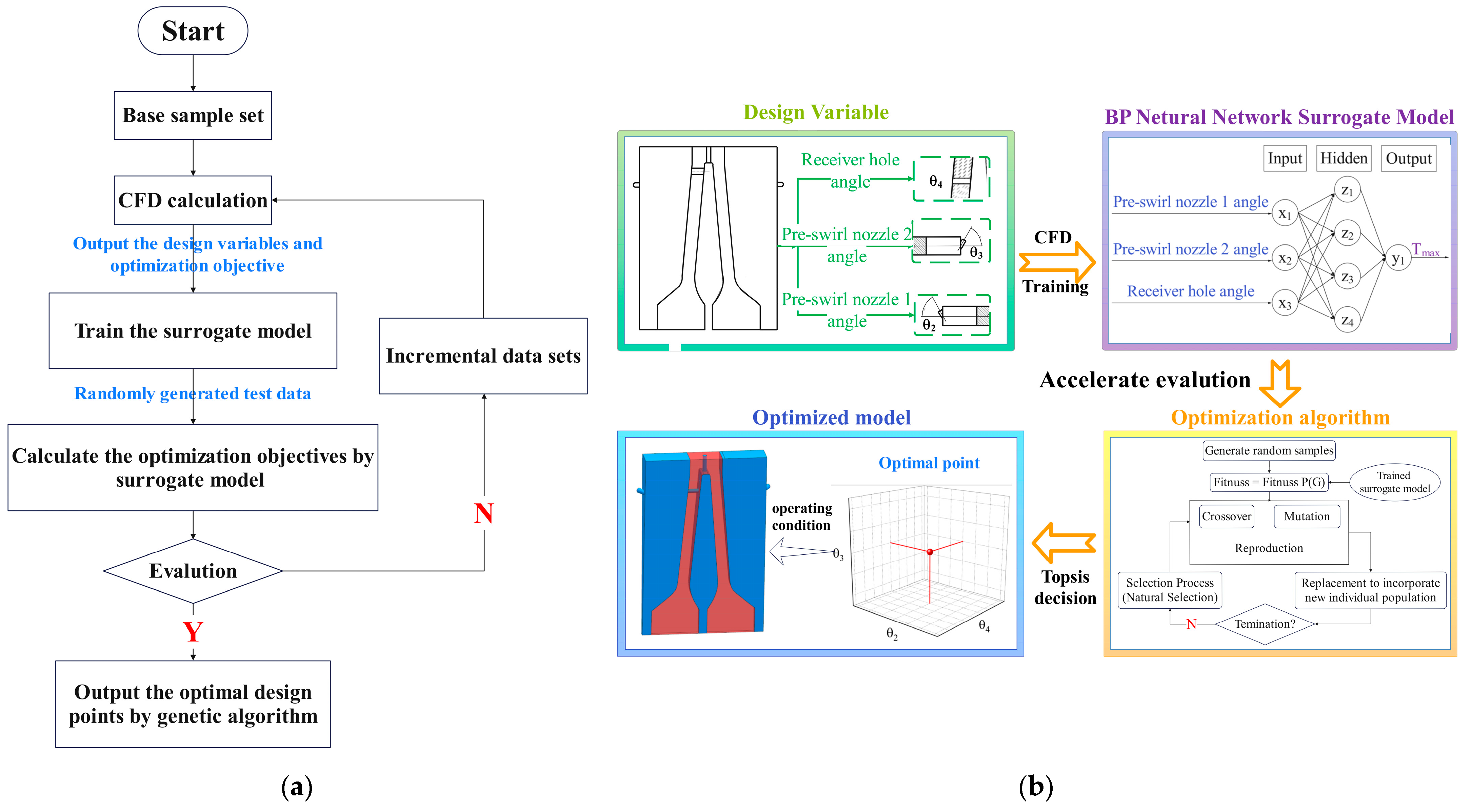
2. Calculation Process

2.1. Model and Boundary Conditions

This paper presents a study on a twin-web turbine disc cavity system based on a design from the literature [20]. The system consists of a twin-web turbine disc with two hubs, two rotor-stator cavities, and an inner cavity formed by these two webs. The disc features 60 pre-swirl nozzles on both sides of the hub, each with a diameter of 6 mm. Additionally, there are 60 cooling fluid outlets with a diameter of 5 mm evenly distributed along the disc edge. On the right side of the disc edge, there is a cooling fluid outlet slit with a fluid width of 3 mm. Three-quarters of the model is depicted in Figure 2a. The dimensions of the system can be found in Figure 2b, and Table 1 provides the main parameter values.
Coolant from pre-swirl nozzle 1 flows into rotor-stator cavity 1 to cool the outer wall of the front web during operation. The fluid enters the inner cavity via the receiver holes on the turbine disc, where it combines with coolant from the central inlet to cool the inner wall of the turbine disc. The mixture exits from the middle of the outlet, contributing to the cooling of the turbine blades. Coolant from nozzle 2 flows into rotor-stator cavity 2 to cool the outer wall of the rear web and exits through the outlet seam.
The 1/60 amount of the TWD system is chosen in this article to save computational resources. In the system, rotor-stator cavity 1 and the inner cavity are combined into fluid domain 1, while rotor-stator cavity 2 is considered as fluid domain 2. The TWD is treated as the solid domain. The calculation domain of the model comprises fluid domain 1, fluid domain 2, and the solid domain. Structured meshes are utilized to mesh both the fluid and solid domains.
The rotating disc is made of a GH4169 superalloy, and the specific parameters are shown in Table 2.
The numerical simulation calculation assumes that the coolant is an ideal gas. In the solid domain, all walls are considered non-slip boundaries. The specific boundary conditions can be found in Table 3.

2.2. Grid and Independence

The rotation test carried out by Xu et al. [33] is cited to validate the accuracy of the turbulence model. There are 30 high-radius pre-swirl nozzles with a diameter of 6mm, and the pre-swirl angle is 30° in the test. The coolant enters the disc cavity through the pre-swirl nozzles, and after completing the cooling task of the disc cavity, it is discharged through the radial outlet hole at the edge of the disc. The edge of the turbine disc is heated through resistance to simulate the convective heat transfer and thermal conduction between the gas and the disc. A simulation model is established based on the geometric conditions of the experiment. The same near-wall mesh treatment as that in this article is utilized. The geometric model and the 1/30 simulation model of the test equipment are presented in Figure 3.
Three turbulence models in CFX were selected for validation: k-ε, k- ω , SST and RNG k-ε.
As stated in the literature:
T = T l T i n
Here, T is the excess temperature on the windward side, T l is the local temperature, and T i n is the inlet temperature. Through the calculation of the excess temperature of the windward side, the influence of the inlet temperature is ignored. The excess temperature of the windward side predicted by numerical simulation is compared with the experimental data, as shown in Figure 4. The results show that the test data of the k-ε turbulence model are more consistent with the trend in the experimental data. Among them, the test data of RNG k-ε is in better agreement with the experimental data of the high radius position. Therefore, in this paper, the RNG k-ε turbulence model is chosen for subsequent calculations.
The computational domain consists of both fluid domains (rotor-stator cavity 1, rotor-stator cavity 2, and the inner cavity) and the solid domain (the twin-web turbine disc). To accurately capture the temperature and velocity gradients near the turbine disc wall, the mesh near the boundary layer is refined. The first layer of the grid near the wall has a thickness of 0.05 mm with a growth rate of 1.1. To obtain superior outcomes, it is optimal to possess a slender grid. The ideal grid demands that the y + of the first layer is less than 1. The y + value computed by the RNG k-ε turbulence model is less than 1.
As illustrated in Figure 5, the grid diagram and the results of grid independence verification indicate that when the number of grids exceeds 5,361,857, the maximum temperature (Tmax) error of the turbine disc is less than 1%. Hence, to ensure convergence and minimize computation time, the mesh size of 5,361,857 is selected.

2.3. Evaluation Indicators

The following were selected as evaluation indicators.
(1) The maximum temperature of the turbine disc: Tmax. Tmax is located at the edge of the turbine disc and is the most direct indicator of the cooling effect.
(2) The coefficient of temperature uniformity of the turbine disc.
Temperature uniformity is an important factor that affects the cooling quality and thermal stress distribution of the turbine disc. The radial temperature change curve in Figure 6a indicates that the temperature gradient in the disc is mostly focused in the high-radial area. The temperature increase is modest while r/b is less than 0.5, but it becomes steep when r/b is greater than 0.5, especially after r/b exceeds 0.85. The radial temperature uniformity coefficient is determined for the wall surface above r/b > 0.5 to emphasize the comparison.
Four sets of ABCD points were chosen on the inner and outer walls, as seen in Figure 6b, with each set comprising five feature points. The study analyzed the temperature uniformity of the front and back webs using the temperature data from a series of sites. The study offers temperature data across the disc, crucial for enhancing cooling techniques and minimizing the thermal strain on the turbine disc.
The radial temperature non-uniformity coefficient of the turbine disc is represented by Tvr:
T v r = S t ¯
where t ¯ is the average temperature of all feature points in the series and S is the temperature change.
The smaller the value of Tvr, the better the radial uniformity.
S = 1 n i = 1 n ( t i t ¯ ) 2
where n is the number of feature points and t i is the temperature of that feature point.
As shown in Equation (4), the axial temperature non-uniformity coefficient T n is studied, taking into account the temperature differential between the inside and outside of the turbine disc. As Figure 6b shows, the temperature difference between the A series point and the B series point, and the temperature difference between the C series and the D series points were selected as the basis for judging the axial temperature uniformity, which was expressed as Tn1 and Tn2, respectively.
T n = T 1 T 2
Similarly, the axial uniformity improves with a reduced T n value.
(3) The Nusselt number. The Nusselt number directly reflects the coolant and the heat transfer intensity of the turbine disc wall.
N u = q r λ ( T T C )
where q is the wall heat flux density, r is the radial position, λ is the thermal conductivity of the air, T is the local temperature, Tc is the reference temperature, and 700 K is selected as the reference temperature in this paper. The Nusselt number is directly related to the temperature gradient.

3. Design Parameters and Methods

Advancements in computer power have elevated the finite element approach to a crucial technology in aeroengine design due to its high computational requirements. However, to optimize intricate systems like gas turbines, it is necessary to investigate multiple design spaces. This might result in expensive computations if all design assessments rely on computationally intensive finite element methods. One common method is to develop a surrogate model to predict the results of a costly solution [34]. The surrogate model elucidates the relationship between the objective function or constraint function and the design variable using a succinct formal equation. This can decrease the reliance on costly finite element analysis, address regions of the design space lacking solutions, and significantly cut down on the computational time required to attain the optimal design. The surrogate model approach is frequently utilized in engineering optimization to decrease computational expenses.

3.1. Design Parameters

The pre-swirl system design impacts coolant flow in the cavity, influencing the cooling of the turbine disc and rotor blades by transferring cooling gas from the compressor stage to the turbine rotor. Gong [35] noted that the technology demonstrates good performance by ensuring the proper operating of turbine blades and efficiently extending their service life. This hypothesis remains relevant in the twin-web turbine disc cavity arrangement. Thus, to enhance cooling efficiency, this study chose the tangential angles of the receiving holes and two pairs of pre-swirl nozzles. Table 4 shows the parameters and ranges to be optimized. Furthermore, the parameters of other twin-web turbine disc cavity systems stay the same.
Figure 7a displays the overall research route. The optimization problem dictates design variables and optimization objectives. Next, for a given range of variables, the number of training samples is ascertained using the orthogonal design approach. Next, all the examples encompassed within the training sample are simulated via CFD using the ANSYS Workbench automatic flow. Values of optimization objectives and design variables are output to build a training sample for training the chosen approximation surrogate model, based on the numerical results of the CFD calculation. The test sample should be generated at random, and its optimization target should be calculated using the CFD calculation and the trained surrogate model. Finally, the genetic algorithm is employed to determine the optimal design point. In case the error is beyond the acceptable range, the number of samples is augmented.
The specific optimization process is shown in Figure 7b. In this study, the BP neural network surrogate model driven by CFD is used to represent the complex relationship between design variables and optimization objectives. The test sample should be randomly generated, the trained surrogate model is used to calculate its optimization target, and the genetic algorithm is used to identify the optimal point. The effectiveness and practicability of the structure optimization technique are verified by numerical simulation.

3.2. BP Neural Network

The design factors chosen in this research to determine Tmax are the tangential angles of pre-swirl nozzle 1, pre-swirl nozzle 2, and the receiving holes. During data preprocessing, 49 sets of design samples were generated using orthogonal decomposition (Supplementary Material: Table S1), and the results were acquired by numerical simulation.
The numerical model findings are utilized to train a three-layer BP neural network. Twelve sets of data are randomly chosen as test sets to validate the accuracy of the neural network’s predictions. The mesh search approach is utilized to optimize the hyperparameters of the neural network for achieving the most accurate prediction outcomes. The determined parameters are a learning rate of 0.1, an acceptable error of 0.03, and a maximum number of iterations set at 200,000. The neural network’s prediction results in the final test set are all within the acceptable error range, as shown in Figure 8. The mean square error (MSE) is 0.02, the mean absolute error (MAE) is 0.04, and the coefficient of determination (R2) is over 98.5. The neural network has attained a high level of accuracy.

3.3. Genetic Algorithm

In this paper, the genetic algorithm was used to optimize the structural parameters. The selection factors pertain to the angles of pre-swirl nozzles 1 and 2, as well as the receiver holes. Tmax is chosen as the fitness function. Elite individuals are chosen based on the fitness function, and their genetic material is mixed and randomly modified to broaden the range of research. By consistently enhancing, the optimal structural characteristics can be achieved. As can be seen from Figure 9, the genetic algorithm can quickly achieve convergence and optimize the structural parameters of the TWD. The optimization results obtained a combination of structural parameters (53, 69, 4) for subsequent analysis.

4. Results and Analysis

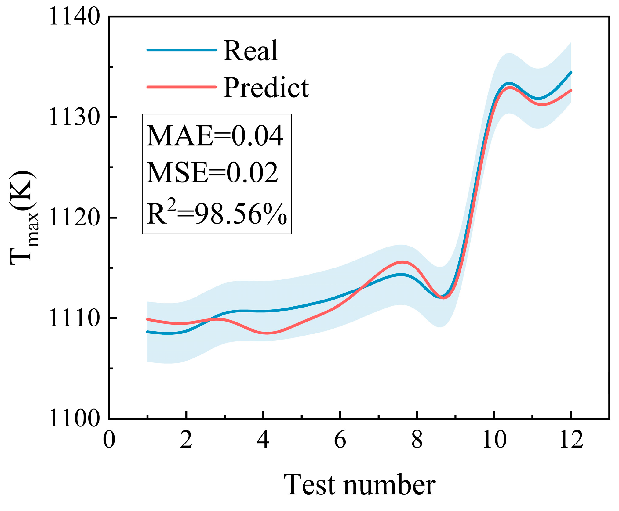
4.1. Comparison of Tmax

As illustrated in Figure 10, the surrogate model developed in this work achieves the prediction of small sample data and, when paired with the genetic algorithm’s optimization outcomes, yields the ideal structural parameters of the TWD and their associated outcomes.
The slicing operation is conducted at consistent 5° intervals in the X-Y plane and fixed 12° intervals in the X-Z and Z-Y planes, as depicted in Figure 10b.
When the angles of the receiver hole rise, combining Figure 10a,b shows a consistent growth of the angular range for temperatures of at least 1120 K. The region with a temperature below 1110 K shrinks as the angles of the receiver hole increase. Furthermore, the Tmax varies at each place with distinct patterns of development and modest variances, indicating that the best angle of the receiver hole should be positioned at a lower value since this angle has little impact on the Tmax. It is clear that the change becomes more noticeable as the angle of pre-swirl nozzle 1 increases, and that the Tmax grows after an initial decrease. Tmax is minimized at an angle of around 50°, leading to the highest level of cooling efficiency. The coolant flowing into pre-swirl nozzle 1 is intended to cool the inner and outer sidewall surfaces of the front web of the turbine disc, leading to a more focused cooling effect at those particular angles. When the angle of pre-swirl nozzle 2 increases, the high-temperature area above 1120 K decreases gradually. Furthermore, in the region where Tmax is lower, there are variable degrees of drop in Tmax, and the general trend of change is not as dramatic as the temperature change resulting from the alteration of pre-swirl nozzle 1. Coolant entering pre-rotating nozzle 2 is believed to solely cool the exterior wall of the back web, partially limiting the overall cooling effect.
Figure 11 displays the Tmax values for the optimized and basic models at different rotating speeds. At speeds ranging from 5000 to 10,000 rpm, the initial velocity is low, leading to a restricted tangential velocity between the coolant and the turbine disc. This results in a poor heat transfer capacity and a high Tmax. Greater velocities lead to enhanced heat transfer and a reduced Tmax. When the rotating speed surpasses 10,000 rpm, the centrifugal force of the air flow in the disc cavities escalates with the turbine disc rotating speed. As a result of the rise in wind resistance temperature, the conversion of thermal work leads to an increase in the turbine disc temperature. The Tmax of the optimized model falls by an average of 23.1 K and a maximum decrease of 32.4 K under varied working conditions, which is better than the basic model in many scenarios. This article explores research results regarding the operational state at 10,000 rpm.
Figure 12 displays the temperature distribution of the disc edge in both the basic and optimized models. The temperature is symmetrical along the axial direction, with the highest temperature at the centre between the outlet and the middle of the disc edge. The temperature decreases gradually towards the edges of the disc. The lower edge of the web disc has a bigger low-temperature area than the front edge due to the outflow slit in rotor-stator cavity 2. There is a notable temperature difference around the middle of the outlet located in the centre of the rim.
In the optimized model, the overall temperature decreases dramatically, especially near the disc edge outflow, where it is around 50 K lower. The enhancement is due to the intricate flow regime within the interior cavity of the improved model. The coolant from the central intake mixes more effectively with the coolant from the receiver hole, improving cooling efficiency. The enhanced mixing and cooling efficiency lead to a reduced overall temperature in the optimized model.

4.2. Comparison of Other Evaluation Indicators

4.2.1. Flow Field Distribution

Figure 13a,b show a comparison between the flow field and temperature distributions of the basic and optimized models. The two models display comparable flows within rotor-stator cavity 1. Coolant flows from pre-swirl nozzle 1, generating two pairs of vortices above and below the nozzle’s exits. The optimized model features a high-radius location with a larger vortex that carries more fluid, resulting in improved cooling due to a higher temperature gradient.
Within the inner cavity, there are two streams of coolant: one originating from the receiver orifice and the other from the middle of the inlet. The flow pattern within the inner cavity is intricate, similar to a co-rotating disc cavity. Hide [36] was the first to analyze the flow properties in the cavity of a co-rotating disc. The flow field can be categorized into four regions: the source region, the core region, the Ekman boundary layer, and the sink region.
The initial model demonstrates the jet developing at the receiver hole, splitting into two sections, leading to the creation of neighbouring vortices in the “core-like region”. In the optimization model, the “source-like region” is fully developed, but the formation of the “Ekman-like boundary layer” is somewhat interrupted, leading to increased convective heat transmission. The optimized model in rotor-stator cavity 2 shows the more efficient impact of the jet from pre-swirl nozzle 2 on the outer wall of the back web.
The optimized model raises the coolant temperature overall, resulting in a bigger high-temperature region at the high radius, particularly in the posterior abdominal wall within the inner cavity, suggesting enhanced cooling efficiency. The optimized model in rotor-stator cavity 2 shows an increased coolant temperature overall and a specific high-temperature area near the edge of the brake disc. The optimized model demonstrates superior flow field distribution and heat transfer properties compared to the basic model.

4.2.2. Temperature Non-Uniformity Coefficient

Figure 14 displays the radial temperature non-uniformity coefficient (Tvr) and axial temperature non-uniformity coefficient (Tn) for both the basic model and the optimized model. The optimized model shows a substantial enhancement in Tvr in comparison to the original model. The Tvr of the B-series and C-series locations in the basic model are nearly equal because of the symmetrical temperature field within the inner cavity. The optimized model shows that intricate flows in high-radius areas improve heat transfer, leading to an uneven temperature distribution. A sudden change in temperature occurred in the posterior abdominal wall, leading to a considerable decrease in temperature, with a 9.96% rise in Tvr at the C-series point compared to the B-series point. The improved model, despite its asymmetry, has a 9.75% lower Tvr than the basic model. Identical alterations were noted at the D-series sites in both models. The optimized model shows a substantial enhancement in radial temperature uniformity, with an average reduction of 11.56% and a maximum reduction of 20.87%.
Figure 14b displays the axial temperature variation between the basic and optimized models. In the basic model, a negative temperature difference between the inner and outer chamber walls suggests that the inner cavity is inadequately cooled and has a high temperature. The optimized model’s inner and outer walls exhibited a reduced temperature difference, suggesting enhanced cooling and improved axial temperature uniformity. The trend of Tn2 in both models is analogous, since the increase in temperature gradient leads to a corresponding increase in radial height and a temperature differential. The average temperature difference in the optimized model has greatly improved, decreasing by 53.62% compared to the basic model. The temperature non-uniformity index decreased by 27.24%.
The optimized model shows enhanced radial and axial temperature variations, which mitigate problems such as the unequal thermal stress concentration, thermal expansion, and thermal fatigue.

4.2.3. Wall Nusselt Number

Figure 15 displays the wall Nusselt numbers for both the basic and optimized models. The Nu number remains consistent before and after optimization, and it grows radially on the wall surface of the rotor-stator cavity. The Nusselt number of rotor-stator cavity 1 experiences a quick change at the receiver hole due to the fluid convergence of the high and low radii, which boosts the heat exchange effect.
The central entrance of the inner cavity exhibits the lowest local Nu number due to the fluid at the hydrostatic inlet having only radial velocity and a slight temperature difference from the reference temperature, leading to inefficient heat exchange. As a result of the improved heat transfer capacity caused by the inlet effect, the Nu number experienced a dramatic increase. As the radial position increases, the boundary layer thickens, leading to a decrease in heat exchange between the cooling fluid and the wall, resulting in a steady decrease in the Nu number. The basic model shows a localized deterioration at the front web wall of the inner cavity, caused by the blockage of cooling fluid entering the receiving hole. This blockage creates a small standing vortex near the wall surface, leading to inefficient heat exchange. The optimized model improves this by adjusting the tangential angle of the receiver hole. Due to the optimized tangential angle of the receiver hole, the flow regime at the high radius position becomes more complex. The “source-like region” fully develops, allowing higher-temperature fluid entering the receiving hole to mix thoroughly with some of the lower-temperature fluid from the central inlet, resulting in improved cooling efficiency.
There is a small local low Nusselt number at the top of the wall surface of rotor-stator cavity 1 due to the formation of a vortex at a high-radius position. This results in standing vortices at the top corner, causing poor heat exchange capacity due to large viscous dissipation and instability. The optimized model has a streamline closer to the wall, resulting in smaller standing vortices compared to the basic model and a better heat transfer efficiency.

5. Conclusions

In the article, a high-fidelity surrogate model is created to enhance the cooling efficiency of the turbine disc by adjusting the angles of the pre-swirl nozzles and the receiver holes. The surrogate model utilizes a BP neural network and a genetic algorithm, driven by a database generated by CFD computation, to optimize the structural parameters of the twin-web turbine disc.
The results of the study showed the following:
  • The surrogate model established by the neural network and the genetic algorithm can effectively solve the objective function and realize the optimal design of the TWD. The results of the GA-BP surrogate model developed in this study closely match those obtained through the finite algorithm.
  • Optimizing the tangential angles of the nozzles and receiver holes significantly impacts the flow of coolant in the cavity, improving heat transfer in high-radius areas, reducing areas with poor heat transfer performance like standing vortices, and enhancing the cooling efficiency of the TWD. The maximum temperature Tmax of the TWD of the optimized model decreases by 23.1 K and 32.4 K on average under different working conditions, which has better performance than the basic model under various working conditions.
  • The temperature at the edge outlet of the optimized model is approximately 50 Kelvin lower than that of the basic model. Furthermore, the axial temperature consistency and radial temperature distribution of the TWD show significant enhancement. The radial temperature non-uniformity coefficient Tvr decreased dramatically, with an average reduction of 11.56% and a maximum reduction of 20.87%. The axial temperature gradient fell, the average temperature gradient decreased by 53.62%, and the axial temperature non-uniformity coefficient also decreased by 27.24%.
  • Compared with the basic model, the Nusselt number of the optimized model has been considerably improved. The trend in the Nusselt number in the rotor-stator cavities remains constant but the value significantly increases. The optimization of the Nusselt number in the inner cavity is particularly noticeable, especially in regions with low heat transfer.
This research demonstrates that optimizing the tangential angles of the pre-swirl nozzles and the receiver holes greatly enhances the cooling efficiency of the TWD. The study of the TWD is multidisciplinary, and further investigation is required to optimize other areas. This paper’s optimization work can be expanded to optimize the design of another high-pressure turbine disc cavity system with a pre-swirl system, offering a research foundation and ideas for future TWD study.

Supplementary Materials

The following supporting information can be downloaded at: https://www.mdpi.com/article/10.3390/en17174346/s1, Table S1: Orthogonal experiment table.

Author Contributions

Conceptualization, Y.G.; methodology, Y.G.; software, Y.G. and W.S.; validation, W.S.; investigation, Y.G.; writing—original draft, Y.G.; writing—review and editing, S.W. and W.S.; visualization, Y.G.; project administration, S.W.; funding acquisition, S.W. All authors have read and agreed to the published version of the manuscript.

Funding

This research was funded by national science and technology major projects of China, grant number Y2022-III-0003-0012.

Data Availability Statement

The original contributions presented in the study are included in the article, further inquiries can be directed to the corresponding author.

Conflicts of Interest

The authors declare no conflicts of interest.

References

  1. Zhang, F.; Wang, X.; Li, J. Numerical investigation of flow and heat transfer characteristics in radial pre-swirl system with different pre-swirl nozzle angles. Int. J. Heat Mass Transf. 2016, 95, 984–995. [Google Scholar] [CrossRef]
  2. Zhang, F.; Wang, X.; Li, J. Numerical investigation on the flow and heat transfer characteristics in radial pre-swirl system with different fillet radius at the junction of inlet cavity and nozzle. Appl. Therm. Eng. 2016, 106, 1165–1175. [Google Scholar] [CrossRef]
  3. Liu, G.-W.; Zhang, L.; Wu, W.-T.; Feng, Q. Numerical simulations on the flow characteristics of the pre-swirl nozzles with different length-to-diameter ratios. J. Propuls. Technol. 2013, 34, 644–650. [Google Scholar]
  4. Ciampoli, F.; Chew, J.W.; Shahpar, S.; Willocq, E. Automatic Optimization of Preswirl Nozzle Design. ASME J. Eng. Gas Turbines Power 2007, 129, 387–393. [Google Scholar] [CrossRef]
  5. Lewis, P.; Wilson, M.; Lock, G.; Owen, J.M. Effect of Radial Location of Nozzles on Performance of Pre-Swirl Systems. In Proceedings of the ASME Turbo Expo 2008: Power for Land, Sea, and Air, Berlin, Germany, 9–13 June 2008; Volume 4: Heat Transfer, Parts A and B. ASME: New York, NY, USA, 2008; pp. 1397–1406. [Google Scholar]
  6. Kakade, V.U.; Lock, G.D.; Wilson, M.; Owen, J.M.; Mayhew, J.E. Effect of radial location of nozzles on heat transfer in pre-swirl cooling systems. In Proceedings of the ASME Turbo Expo 2009, Orlando, FL, USA, 8–12 June 2009; ASME: New York, NY, USA, 2009; Volume 3, pp. 1051–1060. [Google Scholar]
  7. Kong, X.; Huang, T.; Liu, Y.; Chen, H.; Lu, H. Effects of pre-swirl radius on cooling performance of a rotor-stator pre-swirl system in gas turbine engines. Case Stud. Therm. Eng. 2022, 37, 102250. [Google Scholar] [CrossRef]
  8. Ennacer, M.; Guevremont, G.; Djeridane, T.; Sreekanth, S.; Lucas, T. Blade Air Cooling Feed System CFD Analysis and Validation. In Proceedings of the ASME Turbo Expo 2007: Power for Land, Sea, and Air, Montreal, QC, Canada, 14–17 May 2007; Volume 6: Turbo Expo 2007, Parts A and B. ASME: New York, NY, USA, 2007; pp. 1171–1180. [Google Scholar]
  9. Sousek, J.; Pfitzner, M.; Niehuis, R. Experimental Study of Discharge Coefficients for Radial Orifices in High-Speed Rotating Shafts. In Proceedings of the ASME Turbo Expo 2010: Power for Land, Sea, and Air, Glasgow, UK, 14–18 June 2010; Volume 4: Heat Transfer, Parts A and B. ASMEDC: Glasgow, UK, 2010; pp. 1051–1060. [Google Scholar]
  10. Ballal, D.; Zelina, J. Progress in Aero-Engine Technology, 1939–2003 (invited). In Proceedings of the 39th AIAA/ASME/SAE/ASEE Joint Propulsion Conference and Exhibit, Huntsville, AL, USA, 20–23 July 2003; American Institute of Aeronautics and Astronautics: Huntsville, AL, USA, 2003. [Google Scholar]
  11. Cairo, R.R. Twin–Web Rotor Disk. U.S. Patent 5961287[P], 5 October 1999. [Google Scholar]
  12. Cairo, R.R.; Sargent, K.A. Twin web disk: A step beyond convention. J. Eng. Gas Turbines Power 2002, 124, 298–302. [Google Scholar] [CrossRef]
  13. Vasilyev, B.; Salnikov, A.; Semenov, A.; Magerramova, L. Twin-Web Turbine Discs: Part 1—Design and Analysis of Their Efficiency. In Proceedings of the ASME Turbo Expo 2018: Turbomachinery Technical Conference and Exposition, Oslo, Norway, 11–15 June 2018; Volume 7A: Structures and Dynamics, V07AT30A006. ASME: New York, NY, USA, 2018. [Google Scholar]
  14. Wang, B.; Wang, G.; Huang, L.; Xu, S. On the preliminary shape design of axisymmetric twin-web turbine discs considering the burst speed constraint. Eng. Optim. 2022, 54, 2071–2086. [Google Scholar] [CrossRef]
  15. Li, L.; Tang, Z.; Li, H.; Gao, W.; Yue, Z.; Xie, G. Convective heat transfer characteristics of twin-web turbine disk with pin fins in the inner cavity. Int. J. Therm. Sci. 2020, 152, 106303. [Google Scholar] [CrossRef]
  16. Zhang, M.; Gou, W.; Yao, Q.; Li, L.; Yue, Z. Investigation on heat transfer characteristic and optimization of the cooling air inlet for the twin-web turbine disk. J. Phys. Conf. Ser. 2017, 885, 012011. [Google Scholar] [CrossRef]
  17. Zhang, M.; Gou, W.; Li, L.; Yang, F.; Yue, Z. Multidisciplinary design and multi-objective optimization on guide fins of twin-web disk using Kriging surrogate model. Struct. Multidiscip. Optim. 2017, 55, 361–373. [Google Scholar] [CrossRef]
  18. Zhang, M.; Gou, W.; Li, L.; Wang, X.; Yue, Z. Multidisciplinary design and optimization of the twin-web turbine disk. Struct. Multidiscip. Optim. 2016, 53, 1129–1141. [Google Scholar] [CrossRef]
  19. Ma, A.; Liu, F.; Zhou, T.; Hu, R. Numerical investigation on heat transfer characteristics of twin-web turbine disk-cavity system. Appl. Therm. Eng. 2020, 184, 116268. [Google Scholar] [CrossRef]
  20. Ma, A.; Wu, Q.; Zhou, T.; Hu, R. Effect of Inlet Flow Ratio on Heat Transfer Characteristics of a Novel Twin-Web Turbine Disk with Receiving Holes. SSRN Electron. J. 2022, 34, 101990. [Google Scholar]
  21. Brunton, S.; Noack, B.; Koumoutsakos, P. Machine Learning for Fluid Mechanics. Annu. Rev. Fluid Mech. 2020, 52, 477–508. [Google Scholar] [CrossRef]
  22. Brunton, S.L. Applying machine learning to study fluid mechanics. Acta Mech. Sin. 2021, 37, 1718–1726. [Google Scholar] [CrossRef]
  23. Cai, S.; Mao, Z.; Wang, Z.; Yin, M.; Karniadakis, G.E. Physics-informed neural networks (PINNs) for fluid mechanics: A review. Acta Mech. Sin. 2021, 37, 1727–1738. [Google Scholar] [CrossRef]
  24. Zuhal, L.R.; Palar, P.S.; Shimoyama, K. A comparative study of multi-objective expected improvement for aerodynamic design. Aerosp. Sci. Technol. 2019, 91, 548–560. [Google Scholar] [CrossRef]
  25. Jilin, L.; Shunwen, X.; Yi, L.; Xiwen, D.; Ao, T.; Lin, D. Multi-objective optimisation of heat transfer and structural strength of aero-piston air-cooled engine cylinder based on orthogonal test. Therm. Sci. Eng. Prog. 2024, 50, 102500. [Google Scholar] [CrossRef]
  26. Zhang, M.; Liu, D.; Liu, Y. Recent progress in precision measurement and assembly optimization methods of the aero-engine multistage rotor: A comprehensive review. Measurement 2024, 235, 114990. [Google Scholar] [CrossRef]
  27. Jia, X.; Zhou, D.; Hao, J.; Ma, Y.; Peng, Z. Dynamic simulation based on feature transfer learning with source domain adaptive optimization: Application of data-driven model for aero-engines. Measurement 2023, 223, 113786. [Google Scholar] [CrossRef]
  28. Li, B.; Gu, C.; Li, X.; Liu, T. Numerical optimization for stator vane settings of multi-stage compressors based on neural networks and genetic algorithms. Aerosp. Sci. Technol. 2016, 52, 81–94. [Google Scholar] [CrossRef]
  29. Xiang, S.; Qin, Y.; Luo, J.; Pu, H.; Tang, B. Multicellular LSTM-based deep learning model for aero-engine remaining useful life prediction. Reliab. Eng. Syst. Saf. 2021, 216, 107927. [Google Scholar] [CrossRef]
  30. Aygun, H.; Turan, O. Application of genetic algorithm in exergy and sustainability: A case of aero-gas turbine engine at cruise phase. Energy 2022, 238, 121644. [Google Scholar] [CrossRef]
  31. Liu, P.; Han, H.C.; Bao, Z. Multi-objective optimization of fuel–air tube-in-tube helical coil heat exchangers for cooled cooling air system applied in aeroengines. Aerosp. Sci. Technol. 2022, 130, 107933. [Google Scholar] [CrossRef]
  32. Zhang, C.; Gümmer, V. Multi-objective optimization and system evaluation of recuperated helicopter turboshaft engines. Energy 2020, 191, 116477. [Google Scholar] [CrossRef]
  33. Xu, G.Q.; Zhang, S.; Luo, X.; Ding, S.T.; Tao, Z.; Lei, B. Experimental investigation on heat transfer in shrouded rotating disk with high-positioned air inflow. J. Aerosp. Power 2006, 21, 820–823. (In Chinese) [Google Scholar]
  34. Forrester, A.; Sobester, A.; Keane, A. Engineering Design via Surrogate Modelling: A Practical Guide; John Wiley & Sons: Hoboken, NJ, USA, 2008. [Google Scholar]
  35. Gong, W.; Liu, G.; Wang, J.; Wang, F.; Lin, A.; Wang, Z. Aerodynamic and thermodynamic analysis of an aero-engine pre-swirl system based on structure design and performance improvement. Aerosp. Sci. Technol. 2022, 123, 107466. [Google Scholar] [CrossRef]
  36. Hide, R. On source-sink flows in a rotating fluid. J. Fluid Mech. 1968, 32, 737–764. [Google Scholar] [CrossRef]
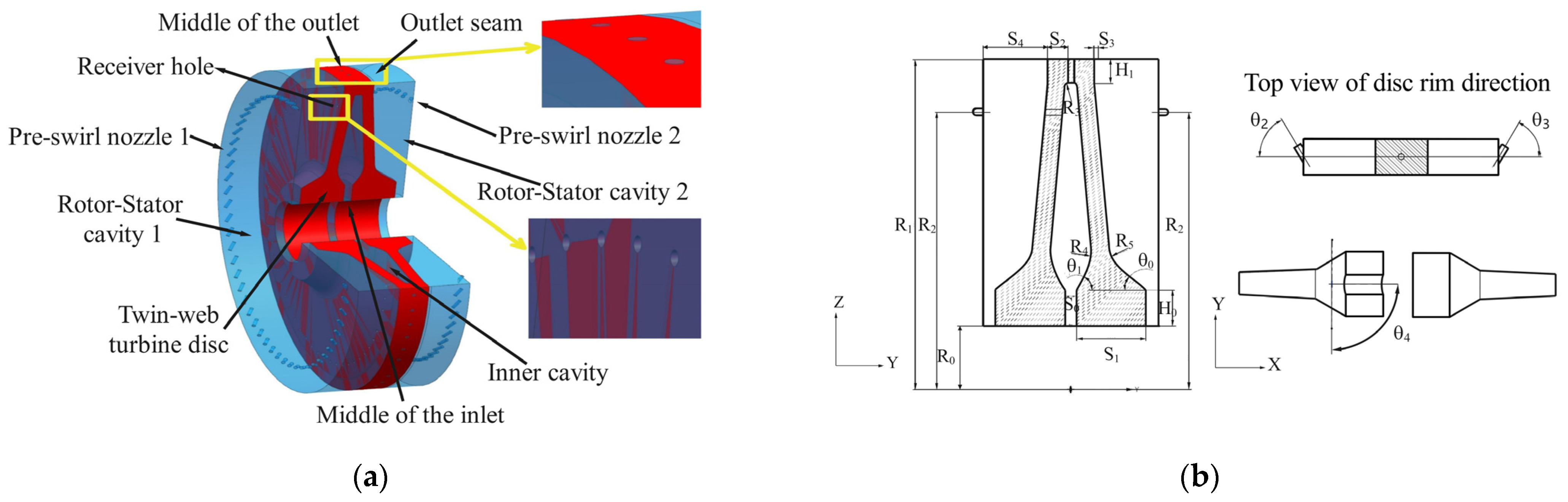
Figure 1. Schematic diagram of (a) SWD and (b) TWD.
Energies 17 04346 g001
Figure 2. Three-dimensional geometry (3/4 model) (a) and structural parameters (b) of the TWD with receiver holes.
Energies 17 04346 g002
Figure 3. (a) Test equipment and (b) simmulation model of for validation.
Energies 17 04346 g003
Figure 4. Experimental validation.
Energies 17 04346 g004
Figure 5. (a) Grids diagram and (b) grids independence verification.
Energies 17 04346 g005
Figure 6. (a) Radial temperature distribution of the TWD at different speeds; (b) feature points.
Energies 17 04346 g006
Figure 7. (a) Overall research route and (b) specific optimization process.
Energies 17 04346 g007
Figure 8. Neural network test results.
Energies 17 04346 g008
Figure 9. Genetic Algorithm Convergence.
Energies 17 04346 g009
Figure 10. Predicted result (a) of the surrogate model, and (b) of each angle.
Energies 17 04346 g010
Figure 11. Tmax under different working conditions.
Energies 17 04346 g011
Figure 12. Temperature distribution of the disc edge (a) of the basic model, and (b) of the optimized model.
Energies 17 04346 g012
Figure 13. Airflow structure and flow field temperature distribution (a) of the basic model, (b) of the optimized model.
Energies 17 04346 g013
Figure 14. Temperature uniformity comparison (a) of radial Tvr, and (b) of axial Tn.
Energies 17 04346 g014
Figure 15. Nusselt distribution (a) of the basic model, and (b) of the optimized model.
Energies 17 04346 g015
Table 1. Geometric parameters of the TWD cavity system.
Geometric ParameterSymbolUnitDesign Value
Height of disc hubH0mm31
Height of disc rimH1mm20
Inner radius of discR0mm53.5
Outer radius of discR1mm281
Center radius of nozzle inletR2mm236
Radius of outlet arcR3mm2.5
Radius of inlet arc (inside)R4mm50
Radius of inlet arc (outside)R5mm25
Width of the middle of the inletS0mm10
Width of disc bottomS1mm58.8
Width of single disc edgeS2mm40
Width of outlet seamS3mm3
Disc spacingS4mm54.8
Outer inclination angle of webӨ0°40
Inner inclination angle of webӨ1°60
Pre-swirl nozzle’s 1 angleӨ2°24–72
Pre-swirl nozzle’s 2 angleӨ3°24–72
Receiver hole’s angleӨ4°0–30
Table 2. GH4169’s physical property parameters.
T/K673773873973107311731173
Parameters
Thermal conductivity/(W/(m·K))18.319.621.222.823.627.630.4
Specific heat capacity/(J/(kg·K))493.9514.8539.0573.4615.3657.2707.4
Density/(g/cm3)8.248.248.248.248.248.248.24
Table 3. Boundary conditions.
LocationSymbolUnitValues
Pre-swirl nozzle 1Inlet/Mass flowkg/s0.0083
Pre-swirl nozzle 1Inlet/Total temperatureK700
Middle of the inletInlet/Mass flowkg/s0.0083
Middle of the inletInlet/Total temperatureK700
Pre-swirl nozzle 2Inlet/Mass flowkg/s0.0083
Pre-swirl nozzle 2Inlet/Total temperatureK700
Middle of the outletOutlet/Average static pressureMPa1
Outlet seamOutlet/Average static pressureMPa1
Twin-web turbine discSolid/Rotating speedrev/min10,000
Rim surfaceWall/Heat fluxW/m2420,000
Table 4. Design parameter range.
Geometric ParameterSymbolUnitDesign Value
Pre-swirl nozzle’s 1 angleӨ2°24–72
Pre-swirl nozzle’s 2 angleӨ3°24–72
Receiver hole’s angleӨ4°0–30
Disclaimer/Publisher’s Note: The statements, opinions and data contained in all publications are solely those of the individual author(s) and contributor(s) and not of MDPI and/or the editor(s). MDPI and/or the editor(s) disclaim responsibility for any injury to people or property resulting from any ideas, methods, instructions or products referred to in the content.

