
Calculation and Adjustment of the Activation Temperature of Switchable Heat Pipes Based on Adsorption

 , , , , ,
Abstract

1. Introduction
- Develop, for the first time, a method for calculating the heat transfer properties of switchpipes depending on the configuration and operating conditions. In this context, heat pipes with a wick structure for operation in against-gravity orientation shall also be considered.
- Introduce basic parameters to describe the thermal activation behavior of switchpipes and investigate the influence of adsorbent type and boundary conditions on these parameters.
- Provide methods for designing and optimizing switchpipes for specific applications. In this context consider simple methods as well as more sophisticated methods for a detailed optimization process.
2. Materials and Methods
2.1. Adsorption Equilibria
2.1.1. Description of Adsorption Equilibria
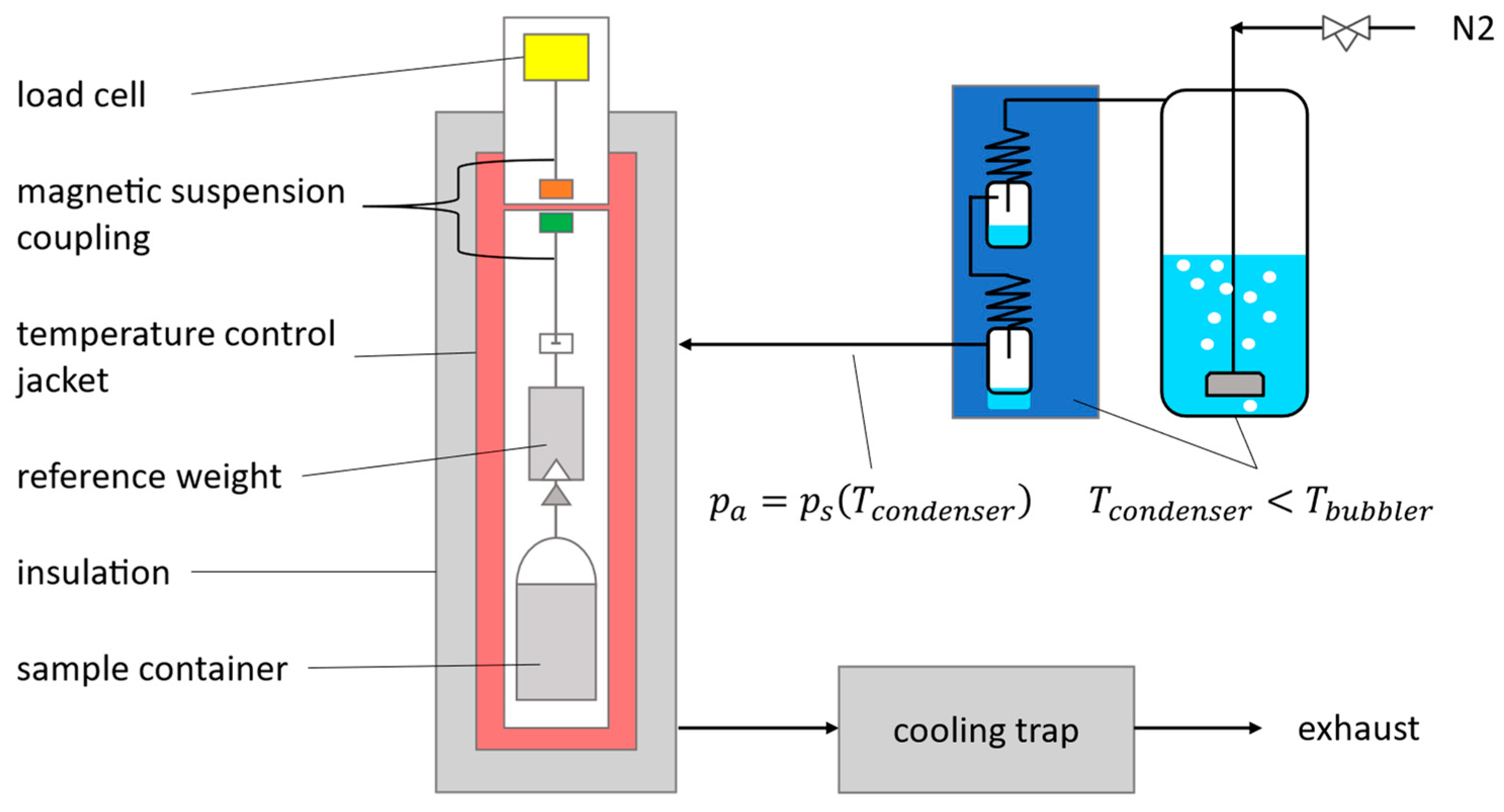
2.1.2. Experimental Investigation of Adsorption Equilibria
2.2. Thermal Resistance of Commercial Heat Pipe (without Adsorbent)
2.3. The Mass Balance-Based Switchpipe Model
- configuration of the heat pipe:
- ○
- Type of adsorbent and its adsorption equilibrium
- ○
- Amount of adsorbent
- ○
- Total amount of working fluid
- ○
- Design-related activation function of the adiabatic mass transfer zone (II)
- boundary conditions:
- ○
- Evaporation zone (III) temperature
- ○
- Condensation zone (I) temperature
3. Results and Discussion
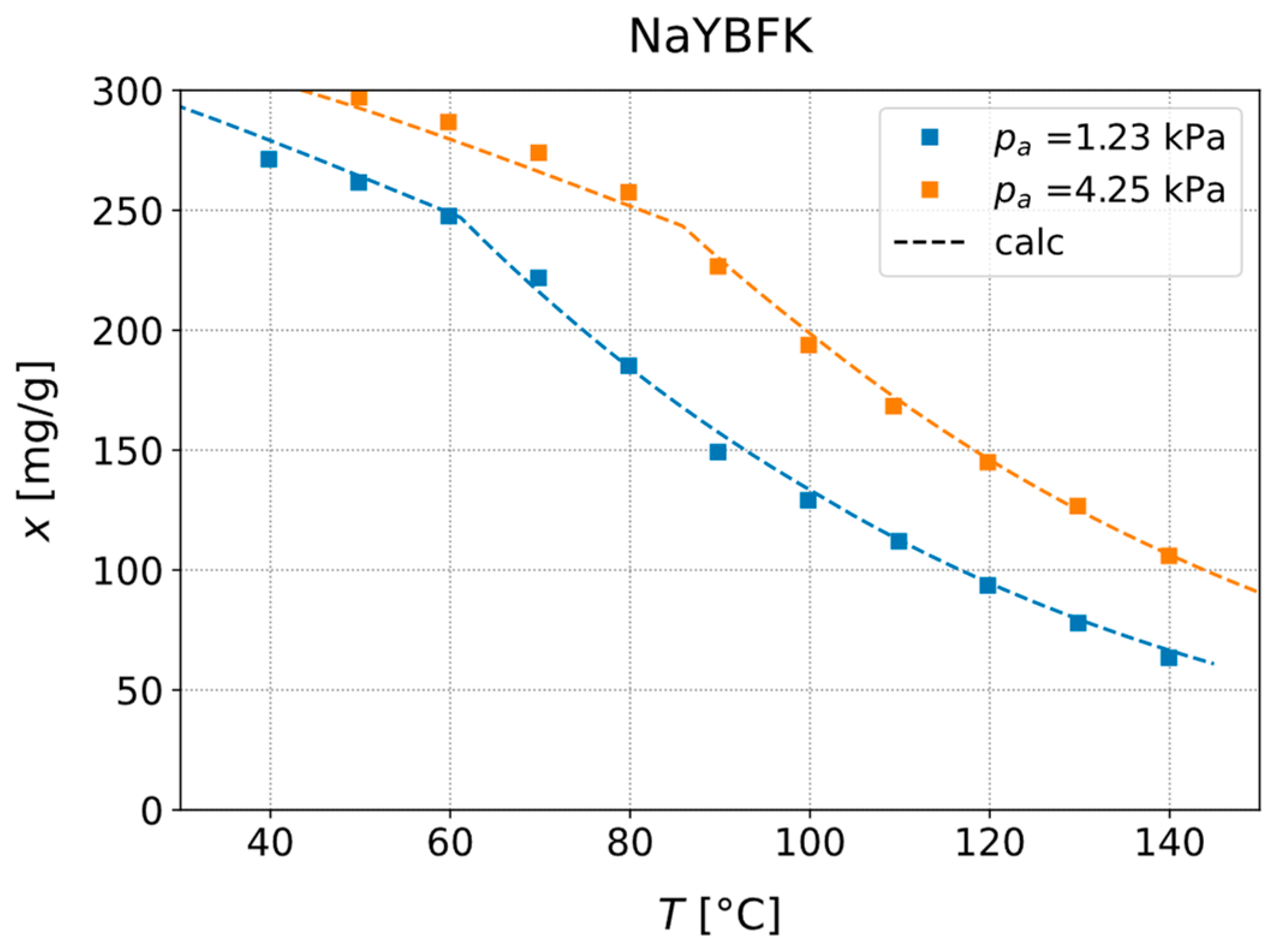
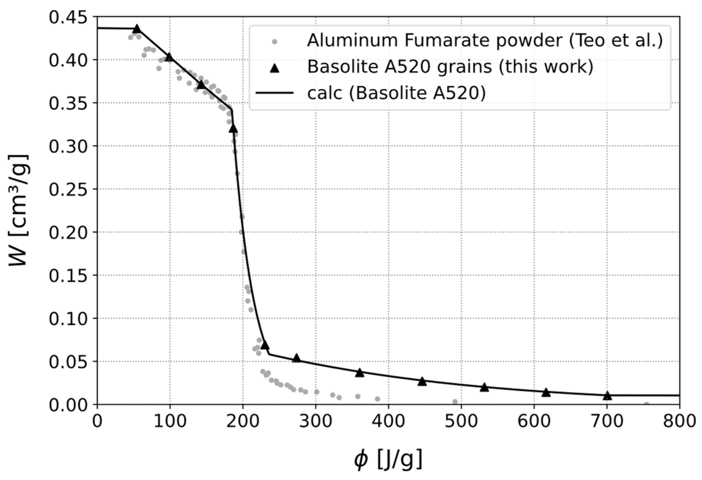
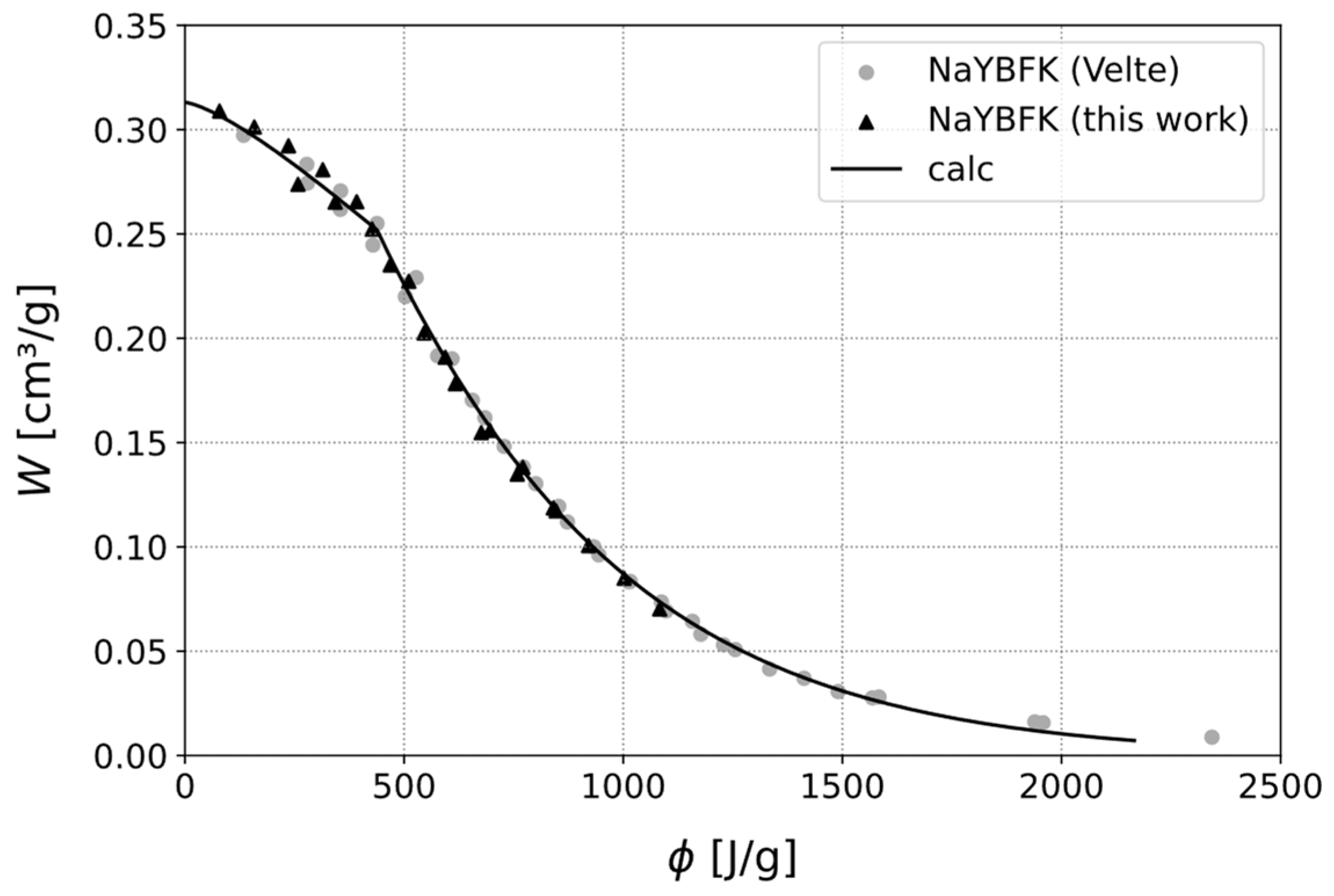
3.1. Experimental Investigation of Adsorption Equilibria
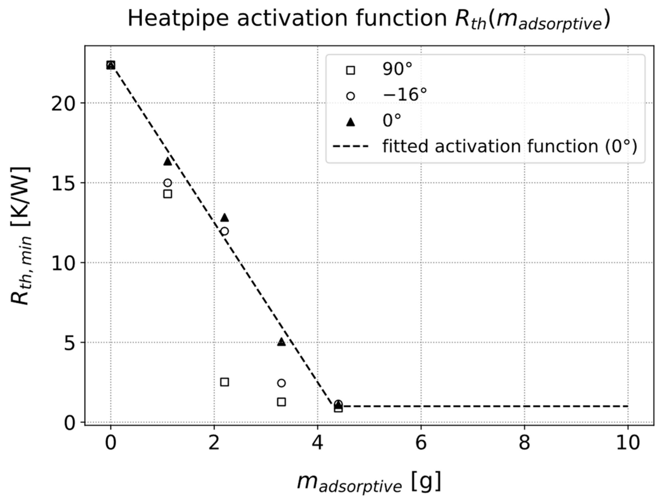
3.2. Thermal Resistance of the Heat Pipe
3.3. The Switchpipe Model
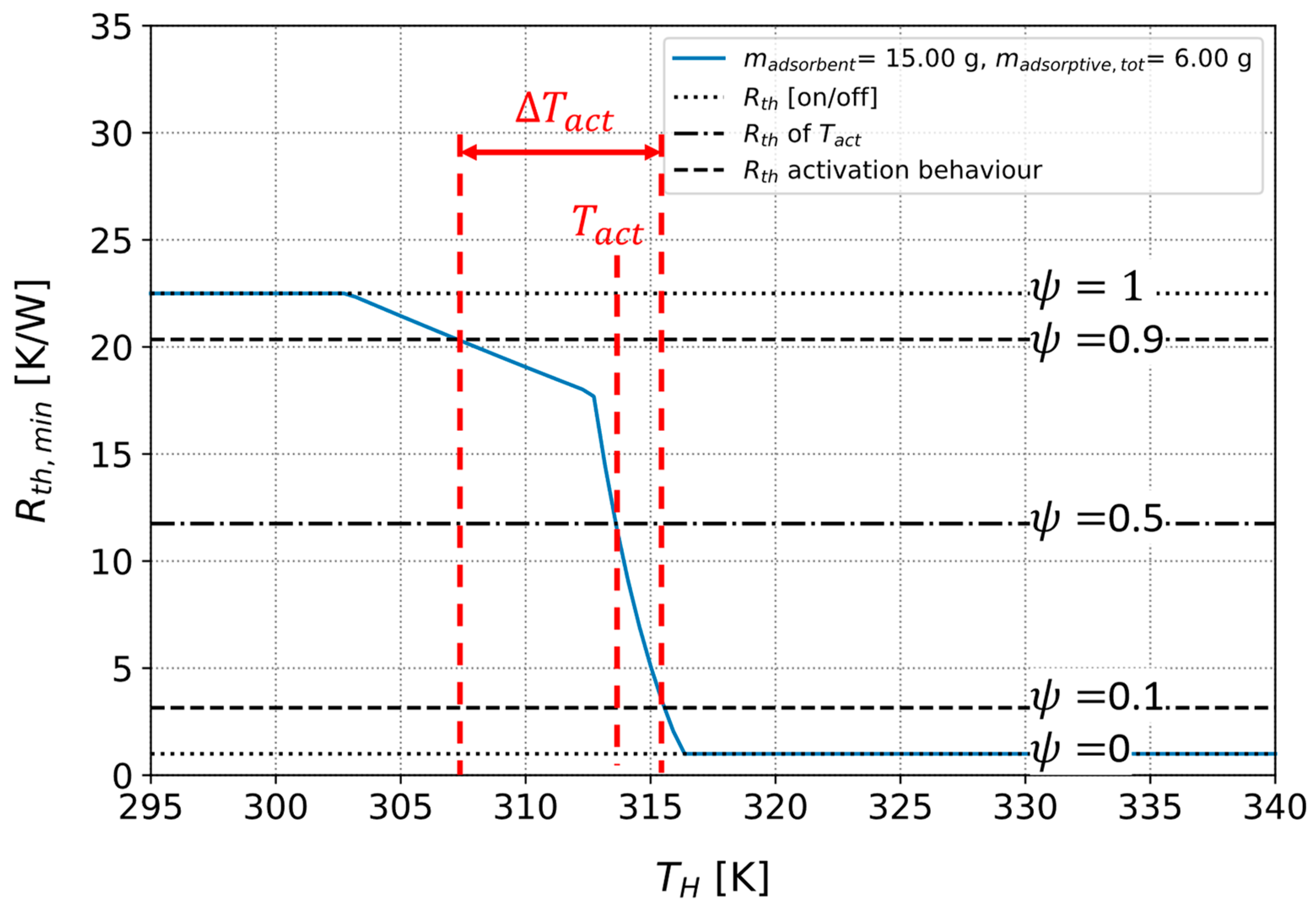
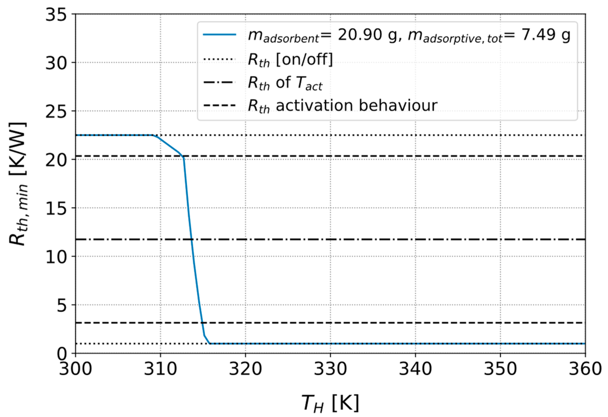
3.3.1. Parameters for Describing the Activation Behavior of the Heat Pipe
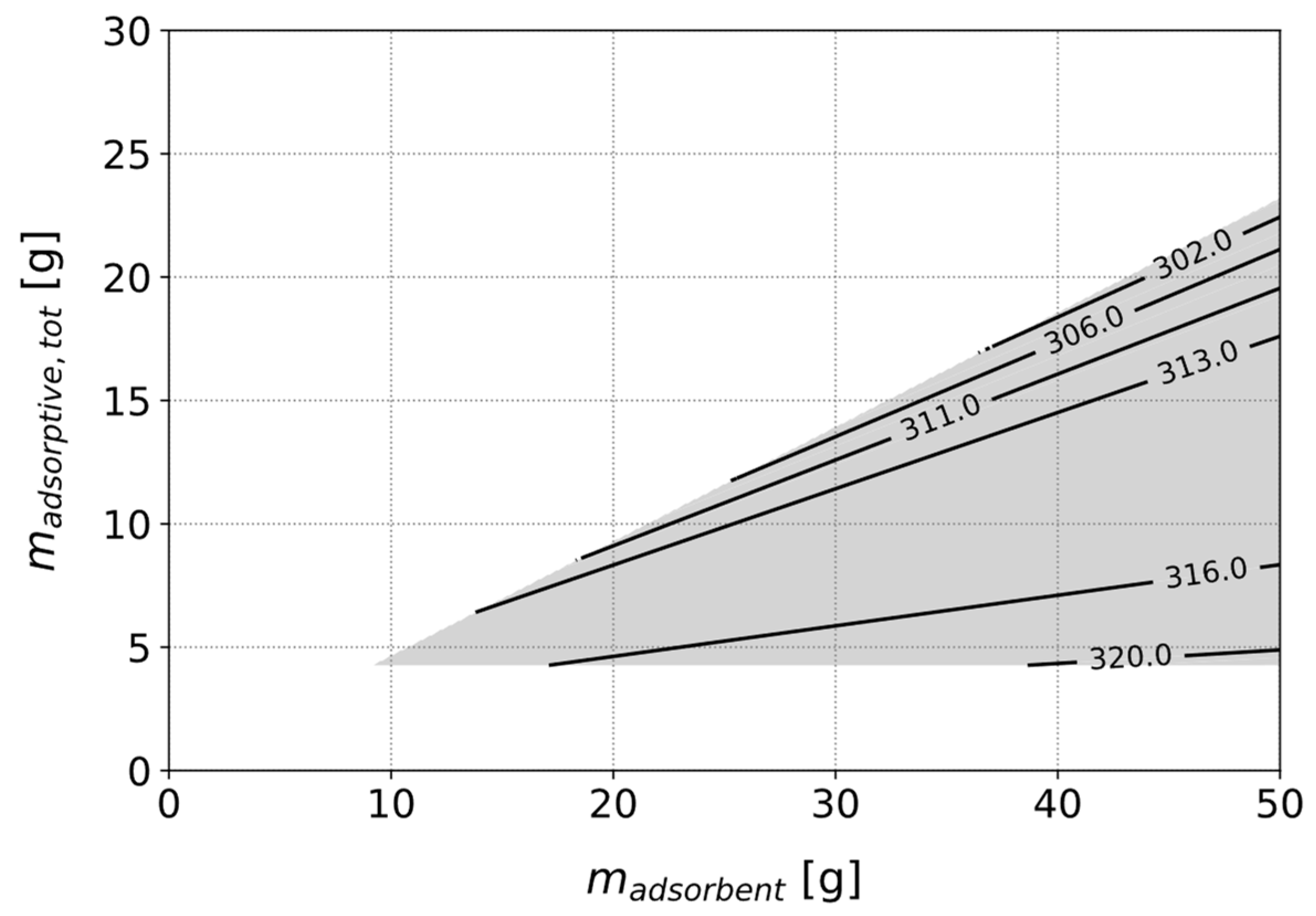
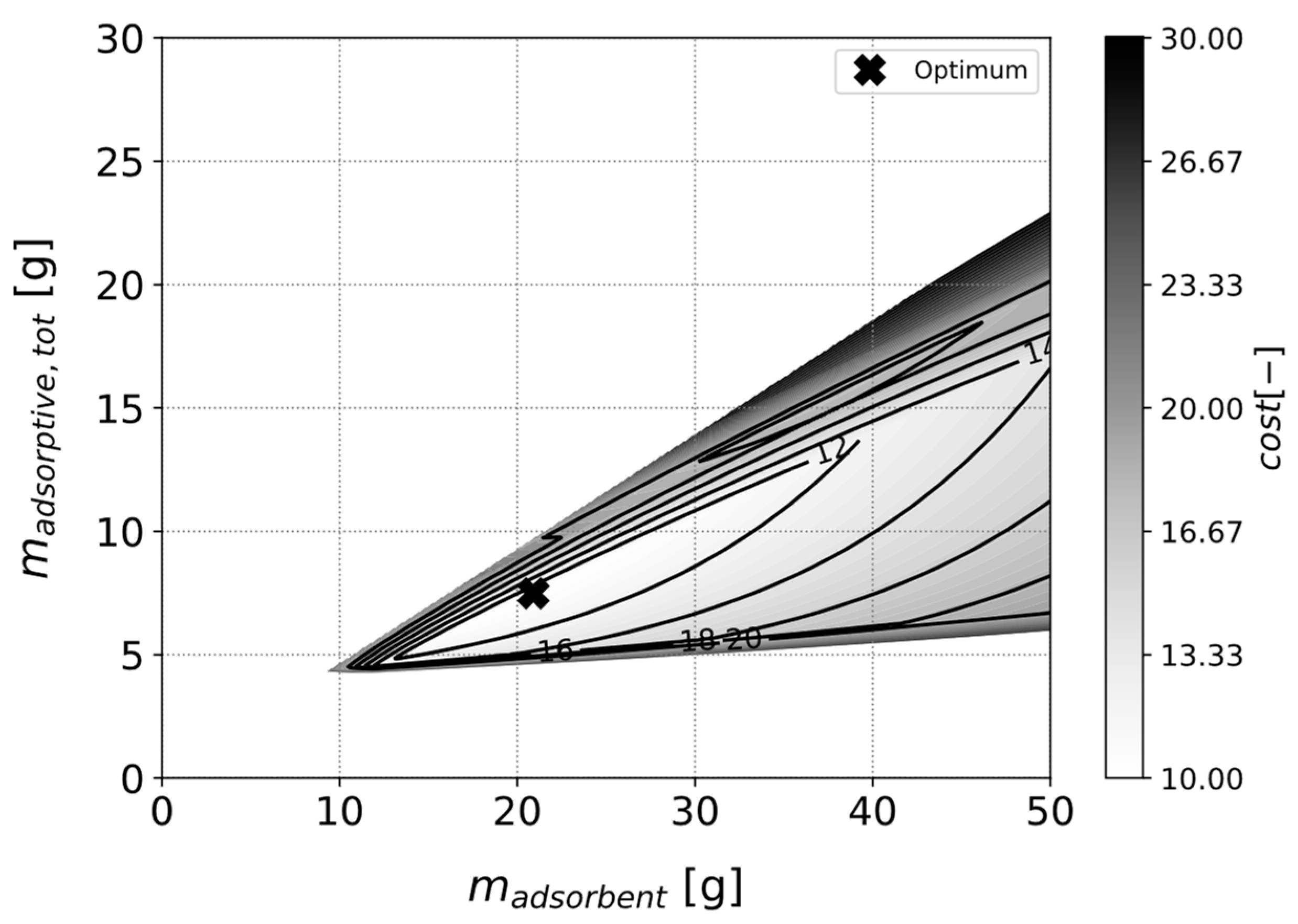
3.3.2. Optimizing a Heat Pipe with Fixed Adsorbent Type
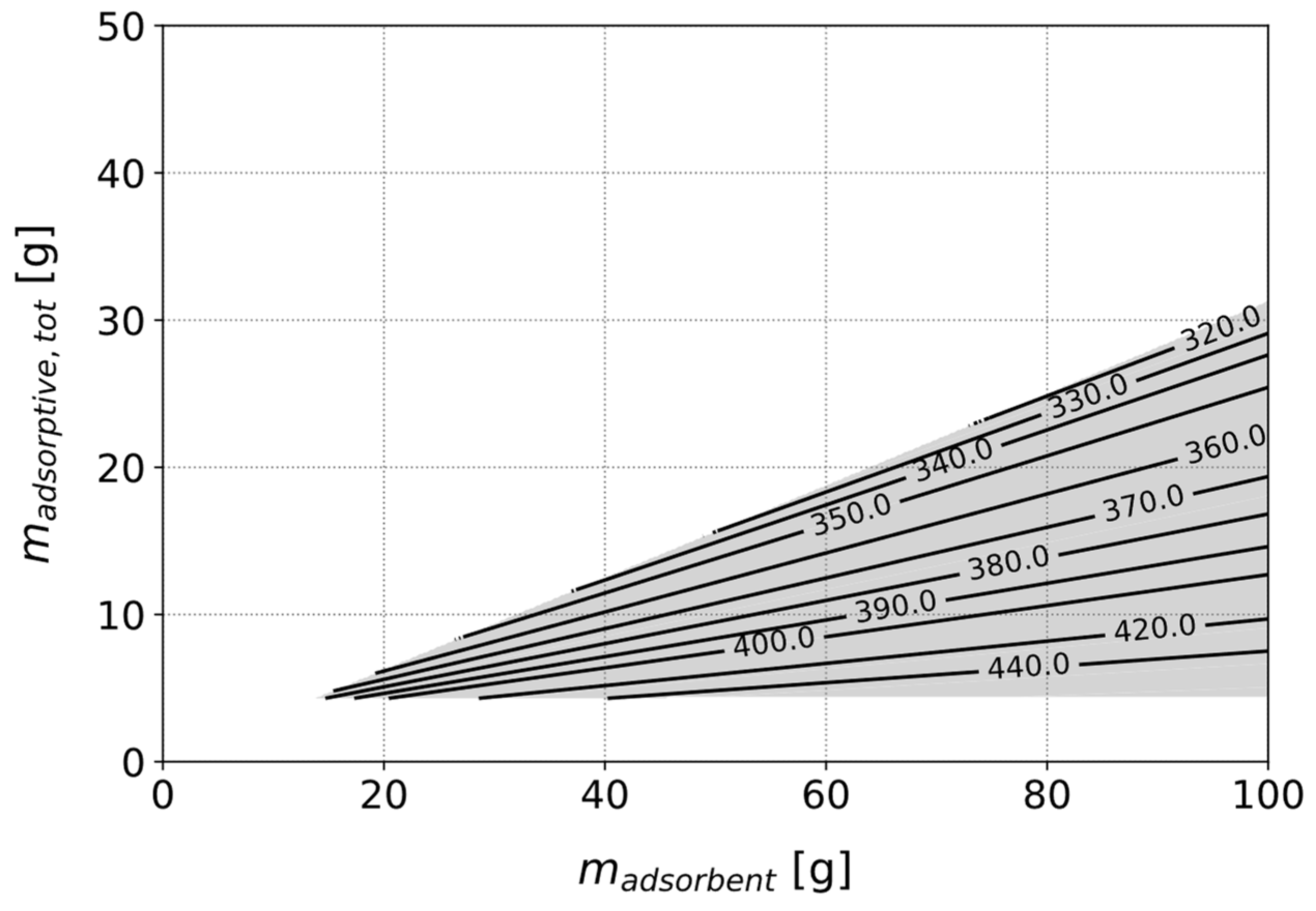
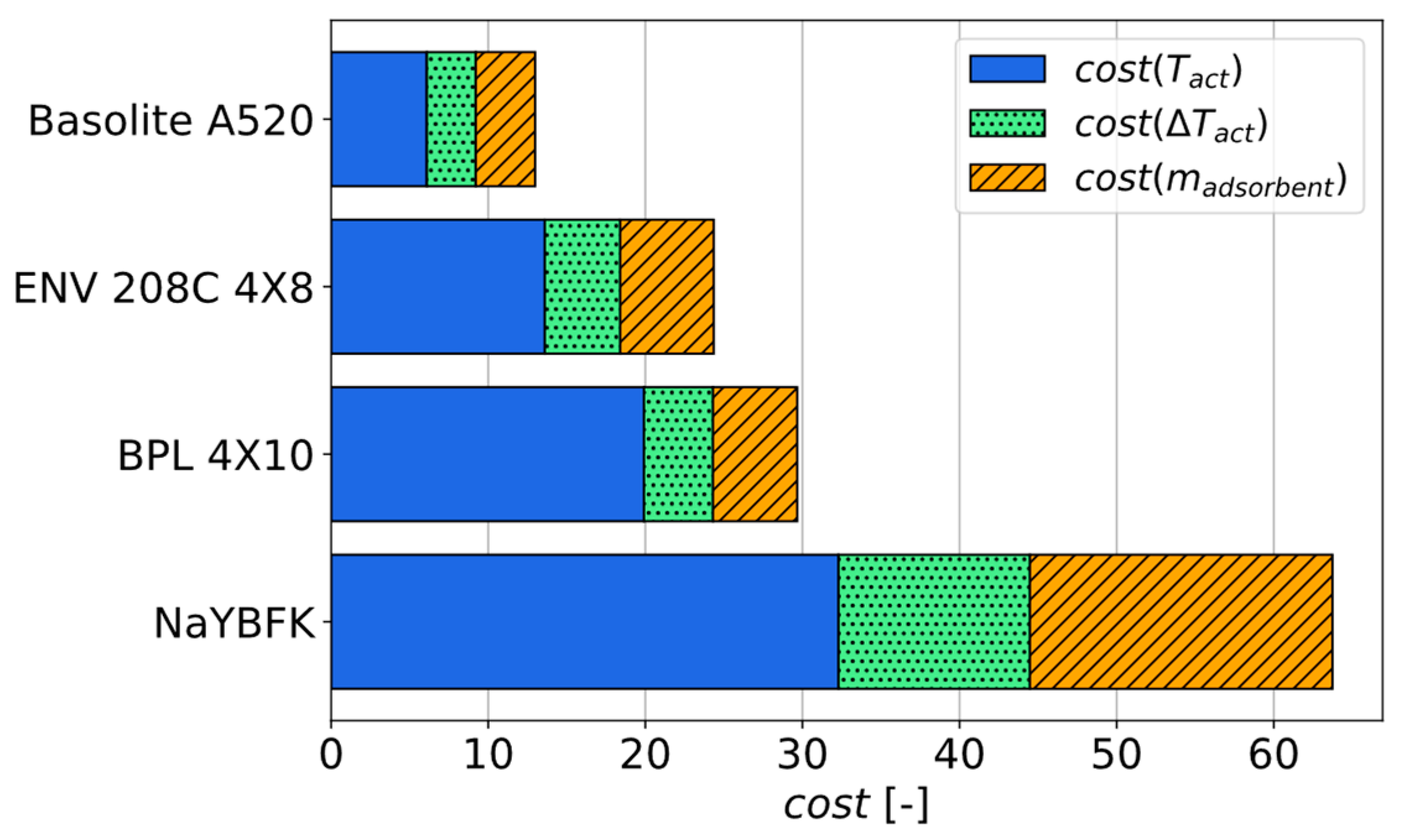
3.3.3. Identification of the Best Adsorbent for a Given Use Case
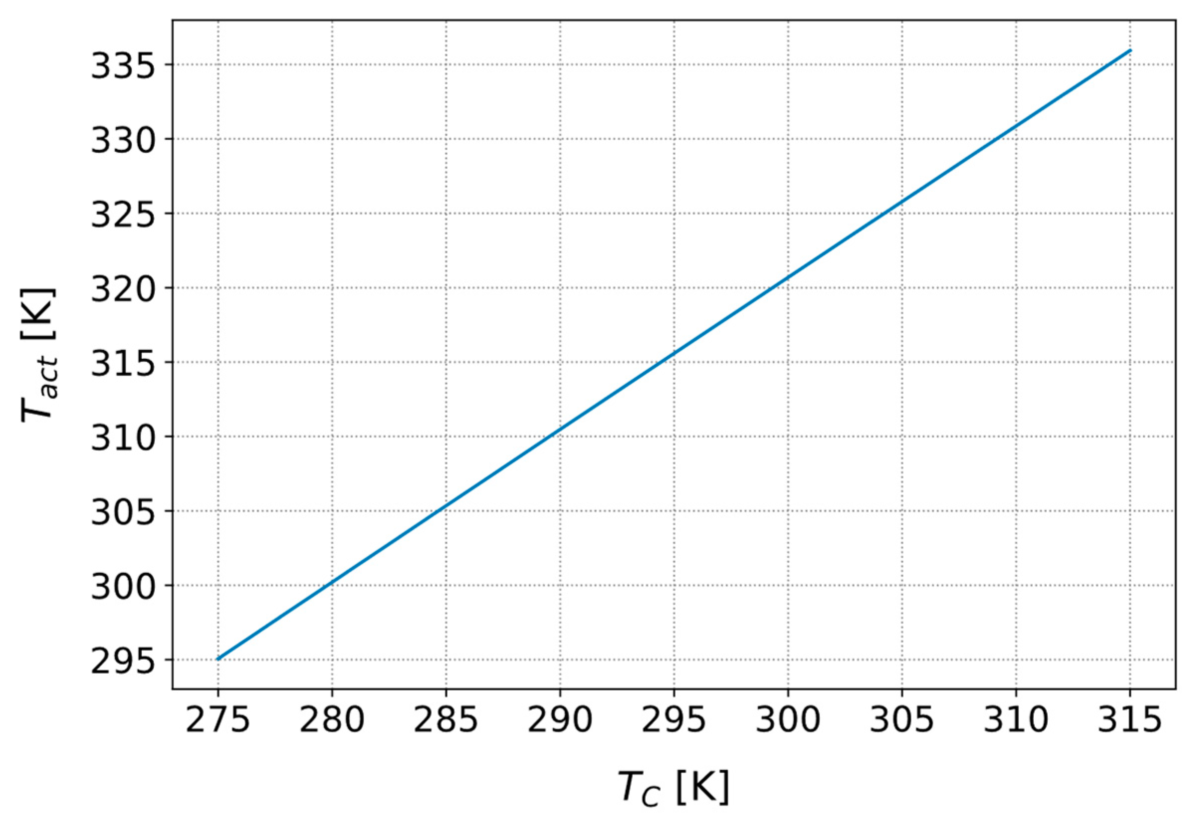
3.3.4. Influence of the Cold Side Temperature on the Activation Temperature
4. Conclusions
5. Patents
Author Contributions
Funding
Data Availability Statement
Conflicts of Interest
References
- Faghri, A. Heat Pipe Science and Technology, 2nd ed.; Global Digital Press: Columbia, MO, USA, 2016; ISBN 978-0984276011. [Google Scholar]
- Wehmeyer, G.; Yabuki, T.; Monachon, C.; Wu, J.; Dames, C. Thermal diodes, regulators, and switches: Physical mechanisms and potential applications. Appl. Phys. Rev. 2017, 4, 41304. [Google Scholar] [CrossRef]
- Winkler, M.; Teicht, C.; Corhan, P.; Polyzoidis, A.; Bartholomé, K.; Schäfer-Welsen, O.; Pappert, S. Thermal Switch Based on an Adsorption Material in a Heat Pipe. Energies 2021, 14, 5130. [Google Scholar] [CrossRef]
- Winkler, M.; Schipper, J.; Teicht, C.; Corhan, P.; Polyzoidis, A.; Bartholomé, K.; Schäfer-Welsen, O.; Pappert, S. Improved Thermal Switch Based on an Adsorption Material in a Heat Pipe. Energies 2022, 15, 3271. [Google Scholar] [CrossRef]
- Winkler, M.; Teicht, C. Heatpipe-basierte Wärmeschalter für Energiesysteme: Neue Konzepte zum regelbaren Wärmetransport. BWK 2023, 75, 47–49. [Google Scholar]
- Illner, M.; Thüsing, K.; Salles, A.; Trettenhann, A.; Albrecht, S.; Winkler, M. Switchable Heat Pipes for Eco-Friendly Battery Cooling in Electric Vehicles: A Life Cycle Assessment. Energies 2024, 17, 938. [Google Scholar] [CrossRef]
- Boda, S.; Winkler, M.; Schießl, R.; Teicht, C.; Schwarz, D.; Schipper, J.; Bartholomé, K.; Schäfer-Welsen, O.; Pappert, S. Improved Switchable Heat Pipe Based on Adsorption: Against-Gravity Operation and Enhanced Dynamics. Energies 2024, 17, 2088. [Google Scholar] [CrossRef]
- Reay, D. Heat Pipes: Theory, Design and Applications, 6th ed.; Elsevier Science: Burlington, VT, USA, 2013; ISBN 978-0-08-098266-3. [Google Scholar]
- Teicht, C. An easy-to-use modification of the potential theory of adsorption and creation of an adsorbent data base. Energy 2023, 263, 125968. [Google Scholar] [CrossRef]
- Dubinin, M.M. Theory of the physical adsorption of gases and vapors and adsorption properties of adsorbents of various natures and porous structures. translated version. Russ. Chem. Bull. 1960, 9, 1072–1078. [Google Scholar] [CrossRef]
- Thommes, M.; Kaneko, K.; Neimark, A.V.; Olivier, J.P.; Rodriguez-Reinoso, F.; Rouquerol, J.; Sing, K.S. Physisorption of gases, with special reference to the evaluation of surface area and pore size distribution (IUPAC Technical Report). Pure Appl. Chem. 2015, 87, 1051–1069. [Google Scholar] [CrossRef]
- Henninger, S. Unified Water Adsortpion Measurement Procedure for Sorption Materials. In Sources/Sinks Alternative to the Outside Air for Heat Pump and Air-Conditioning Techniques, International Sorption Heat Pump Conference 2011, Padua, Italy, 6–8 April 2011; Lazzarin, R.M., Ed.; International Institute of Refrigeration: Paris, France, 2011; pp. 513–522. ISBN 9782913149847. [Google Scholar]
- Teo, H.W.B.; Chakraborty, A.; Kitagawa, Y.; Kayal, S. Experimental study of isotherms and kinetics for adsorption of water on Aluminium Fumarate. Int. J. Heat Mass Transf. 2017, 114, 621–627. [Google Scholar] [CrossRef]
- Velte, A. Experimentelle Arbeiten und Entwicklung von Numerischen Modellen zur Analyse und Optimierung von Erweiterten Adsorptionskreisläufen für die Wärmeversorgung von Gebäuden. Ph.D. Thesis, Albert-Ludwigs-Universität Freiburg, Freiburg im Breisgau, Germany, 2019. [Google Scholar]


| Material | (°C) | (kPa) | (°C) | (°C) |
|---|---|---|---|---|
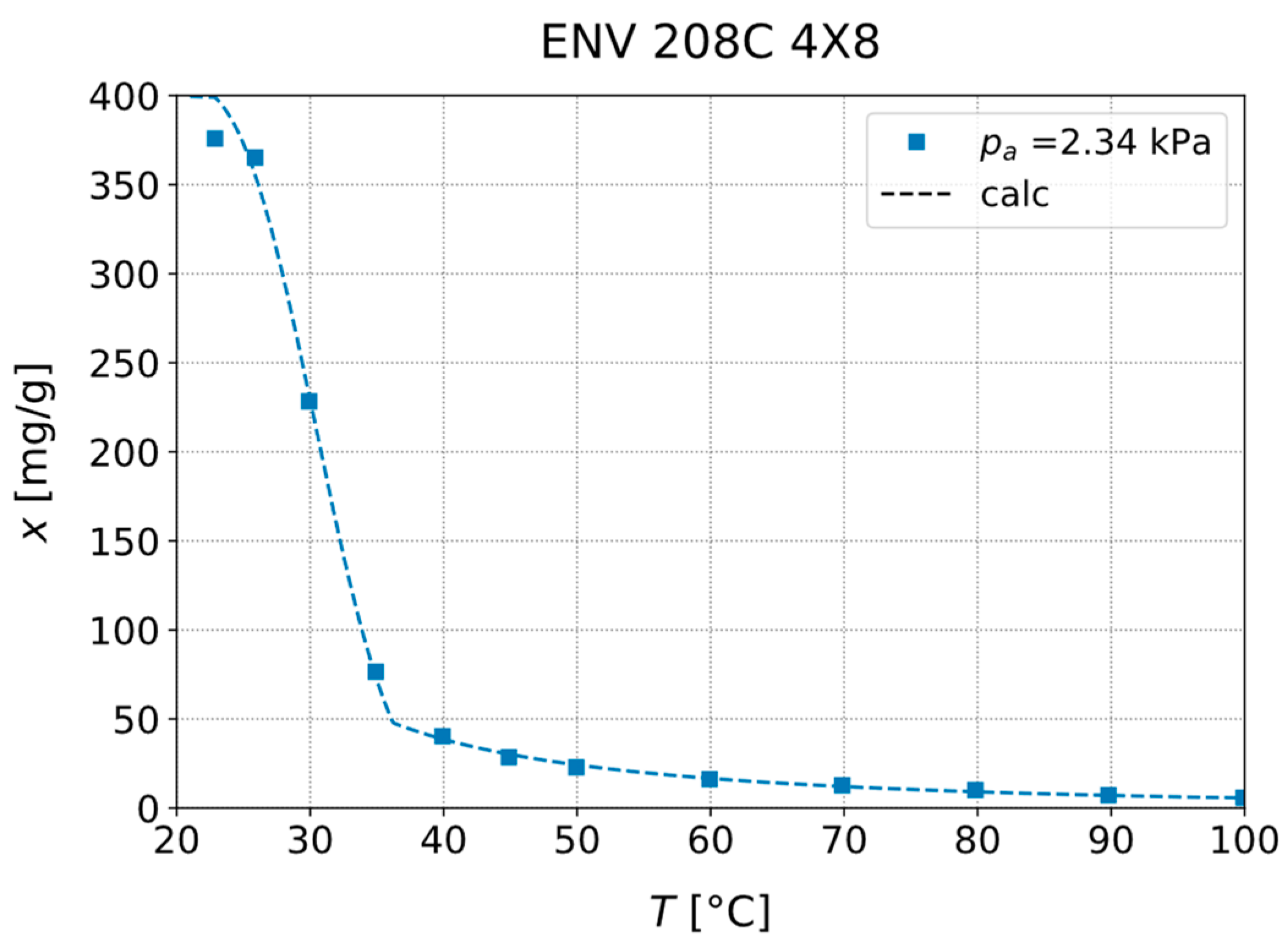
| ENV 208C 4X8 | 150 | 2.339 | 20 | 23–100 |
| BPL 4X10 | 150 | 2.339 | 20 | 23–100 |
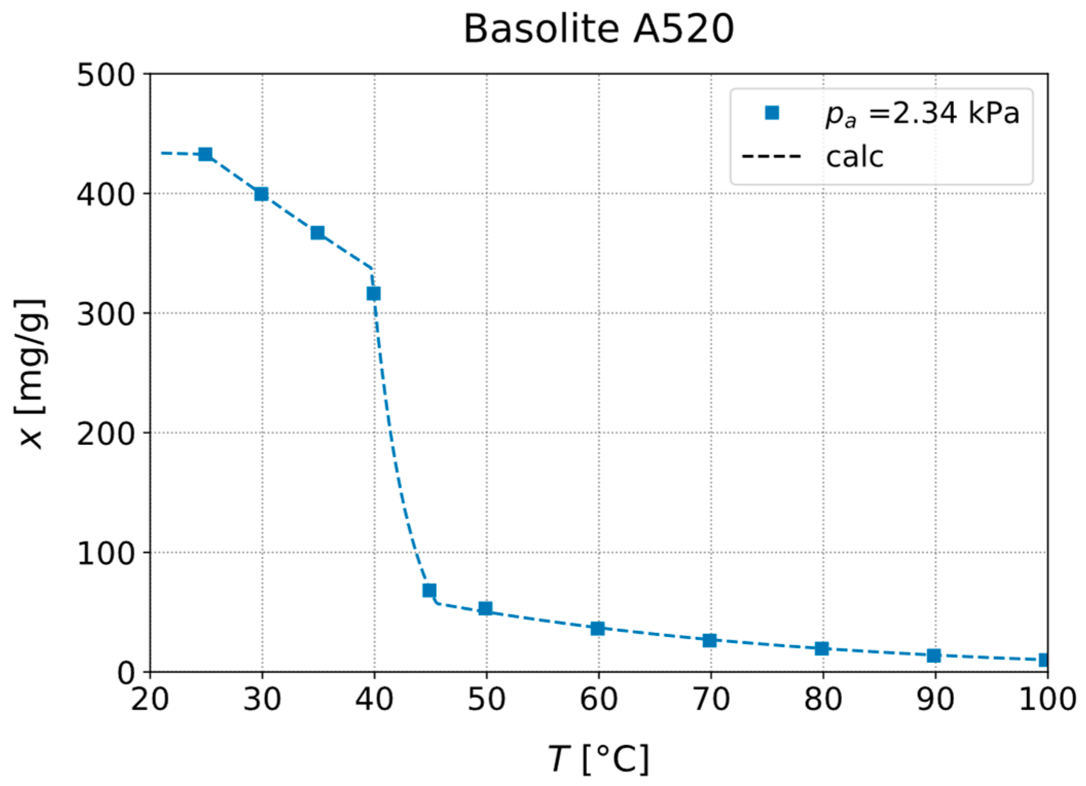
| Basolite A520 | 150 | 2.339 | 20 | 25–100 |
| NaYBFK | 200 | 1.228 | 10 | 40–140 |
| 200 | 4.247 | 30 | 40–140 |
| Material | Isotherm | (g) | (g) | (K) | (K) |
|---|---|---|---|---|---|
| ENV 208C 4X8 | Type V | 24.7 | 7.8 | 10.5 | 4.6 |
| BPL 4X10 | Type V | 23.1 | 7.6 | 5.0 | 4.1 |
| Basolite A520 | Type V | 20.8 | 7.5 | 20.8 | 2.8 |
| NaYBFK | Type I | 81.0 | 20.4 | 60.8 | 15.2 |
| TAPSO-34 | Type V | 49.4 | 8.3 | 36.2 | 4.7 |
Disclaimer/Publisher’s Note: The statements, opinions and data contained in all publications are solely those of the individual author(s) and contributor(s) and not of MDPI and/or the editor(s). MDPI and/or the editor(s) disclaim responsibility for any injury to people or property resulting from any ideas, methods, instructions or products referred to in the content. |
© 2024 by the authors. Licensee MDPI, Basel, Switzerland. This article is an open access article distributed under the terms and conditions of the Creative Commons Attribution (CC BY) license (https://creativecommons.org/licenses/by/4.0/).
Share and Cite
Teicht, C.; Winkler, M.; Boda, S.; Schwarz, D.; Schipper, J.; Polyzoidis, A.; Pappert, S.; Bartholomé, K. Calculation and Adjustment of the Activation Temperature of Switchable Heat Pipes Based on Adsorption. Energies 2024, 17, 4314. https://doi.org/10.3390/en17174314
Teicht C, Winkler M, Boda S, Schwarz D, Schipper J, Polyzoidis A, Pappert S, Bartholomé K. Calculation and Adjustment of the Activation Temperature of Switchable Heat Pipes Based on Adsorption. Energies. 2024; 17(17):4314. https://doi.org/10.3390/en17174314
Chicago/Turabian StyleTeicht, Christian, Markus Winkler, Simon Boda, Daniel Schwarz, Jan Schipper, Angelos Polyzoidis, Sandra Pappert, and Kilian Bartholomé. 2024. "Calculation and Adjustment of the Activation Temperature of Switchable Heat Pipes Based on Adsorption" Energies 17, no. 17: 4314. https://doi.org/10.3390/en17174314
APA StyleTeicht, C., Winkler, M., Boda, S., Schwarz, D., Schipper, J., Polyzoidis, A., Pappert, S., & Bartholomé, K. (2024). Calculation and Adjustment of the Activation Temperature of Switchable Heat Pipes Based on Adsorption. Energies, 17(17), 4314. https://doi.org/10.3390/en17174314