Article

Performance of a Methanol-Fueled Direct-Injection Compression-Ignition Heavy-Duty Engine under Low-Temperature Combustion Conditions

1
Division of Fluid Mechanics, Department of Energy Sciences, Lund University, 22100 Lund, Sweden
2
Department of Mechanical Engineering, School of Engineering, Aalto University, Otakaari 4, 02150 Espoo, Finland
*
Author to whom correspondence should be addressed.
Energies 2024, 17(17), 4307; https://doi.org/10.3390/en17174307
Submission received: 9 July 2024 / Revised: 15 August 2024 / Accepted: 19 August 2024 / Published: 28 August 2024
(This article belongs to the Special Issue Towards Climate Neutral Thermochemical Energy Conversion)

Abstract

:
Low-temperature combustion (LTC) concepts, such as homogeneous charge compression ignition (HCCI) and partially premixed combustion (PPC), aim to reduce in-cylinder temperatures in internal combustion engines, thereby lowering emissions of nitrogen oxides (NOx) and soot. These LTC concepts are particularly attractive for decarbonizing conventional diesel engines using renewable fuels such as methanol. This paper uses numerical simulations and a finite-rate chemistry model to investigate the combustion and emission processes in LTC engines operating with pure methanol. The aim is to gain a deeper understanding of the physical and chemical processes in the engine and to identify optimal engine operation in terms of efficiency and emissions. The simulations replicated the experimentally observed trends for CO, unburned hydrocarbons (UHCs), and NOx emissions, the required intake temperature to achieve consistent combustion phasing at different injection timings, and the distinctively different combustion heat release processes at various injection timings. It was found that the HCCI mode of engine operation required a higher intake temperature than PPC operation due to methanol’s low ignition temperature in fuel-richer mixtures. In the HCCI mode, the engine exhibited ultra-low NOx emissions but higher emissions of UHC and CO, along with lower combustion efficiency compared to the PPC mode. This was attributed to poor combustion efficiency in the near-wall regions and engine crevices. Low emissions and high combustion efficiency are achievable in PPC modes with a start of injection around a crank angle of 30° before the top dead center. The fundamental mechanism behind the engine performance is analyzed.

1. Introduction

Internal combustion engines (ICEs) have been a reliable energy source for decades. Compression-ignition (CI) engines have developed into highly efficient and durable energy sources. However, recent concerns regarding climate change have put the future of ICEs at risk. The use of fossil fuels in ICEs is a significant contributor to greenhouse gas (such as CO2) in the global atmosphere and to the local air pollutants, such as nitrogen oxides (NOx), soot, carbon monoxide (CO), and unburned hydrocarbons (UHCs) [1,2]. As a result, renewable and green fuels, such as hydrogen, methanol, ammonia, butanol, and pine oil, are highly researched [3,4,5,6,7,8]. Historically, alcohols like methanol were used in multi-fuel diesel engines for military vehicles to ensure operational flexibility under varying fuel supply conditions and to prevent fuel freezing in adverse climates. In recent years, with the mounting pressures of the energy crisis and decarbonization, low-carbon fuels are increasingly under the spotlight, particularly alcohol-based fuels such as methanol and ethanol. These fuels have already been commercialized in various regions, including Europe and China. In particular, methanol is a fuel of high interest as it can be produced carbon-neutrally using recycled CO2 and green H2 [4]. Methanol can thus be a hydrogen carrier, is less toxic, is safe to store, and has excellent potential in heavy-duty [9] and marine engines [4,10].
Government bodies have been implementing emission regulations to minimize local air pollution from ICEs, forcing manufacturers to produce engines that meet these low-emission standards. These regulations have successfully been met using techniques such as after-treatment systems, exhaust gas recirculation (EGR), and novel combustion concepts such as low-temperature combustion (LTC). LTC concepts [11] have been recommended, as they aim to lower emissions at the source. LTC concepts aim to reduce emissions at the source by injecting fuel much earlier than conventional diesel combustion (CDC). Early injection allows for significantly more mixing than CDC, and the resulting lean mixtures result in low combustion temperatures, leading to a lower formation of NOx and soot. However, such strategies can impact the engine performance and emissions depending on the fuel and injection strategy/timing used [12].
LTC concepts struggle with stability issues and under low load where overly fuel-lean mixtures cause high CO and UHC emissions due to the early injection [13]. LTC can be split into various sub-categories: homogeneous charge compression ignition (HCCI) [14,15], partially premixed combustion (PPC) [16,17,18], and reactivity-controlled compression ignition (RCCI) [19]. These sub-categories represent various stages of homogeneity, achieved by injecting fuel at a specific time during the compression stroke. HCCI involves very early injection during the compression stroke and achieves a homogeneous fuel/air mixture when combustion is initiated. PPC injects fuel between the HCCI range and CDC, achieving more stratified mixtures than HCCI. While diesel is typically used in CI engines, it is unsuitable for LTC strategies as its low research octane number (RON) makes it prone to premature ignition or knocking with early injection. Instead, high RON fuels are preferred as they can be injected earlier, with a much lower possibility of engine knocking. Due to its high RON, gasoline has been widely investigated in PPC methods [20,21]. However, using high RON fuels in CI engines provides challenges in igniting the fuel without an ignition aid such as a spark plug or higher compression ratio. Li et al. [22] showed that a gasoline LTC engine with a compression ratio of 17.3:1, operating in the HCCI mode at a low load (3–4 bar IMEPg), required a preheated intake air of 140–150 °C. The same engine operating in the PPC mode required less intake air preheating by 40–50 °C, i.e., required a preheating intake air temperature of around 100 °C.
Methanol has a RON of 109 [4]; thus, it faces a similar ignition challenge as gasoline in LTC engines. Methanol has a more simple chemical composition compared to other hydrocarbon fuels, meaning it naturally reduces emissions of NOx and particulate matter (PM). Additionally, methanol has a high heat of vaporization value, three times higher than fossil fuels, which absorbs a much higher temperature during injection, resulting in charge cooling effects. Svensson et al. [23] achieved stable methanol combustion in a heavy-duty CI engine using increased intake temperatures and pilot injections. At a low load of IMEPg of 6 bar and compression ratio of 17.3:1, stable combustion of methanol was not achieved with the highest intake temperature possible; however, by using a methanol pilot in combination with increased intake temperature, stable combustion was achieved. Zincir et al. [24] demonstrated that the intake temperature can affect the combustion stability, engine performance, and emissions and found that high temperatures over 373K were required for the ignition of methanol at a load of 3 bar IMEP with a compression ratio of 20:1. Additionally, it was found that combustion efficiency increases with a higher intake temperature but thermodynamic efficiency experiences no impact. Svensson and Verhelst [25] determined that increasing the intake temperature was more effective than the intake pressure to achieve methanol auto-ignition under PPC conditions.
Methanol has a low stoichiometric air–fuel ratio, implying that a fuel-lean mixture can be achieved faster, i.e., the injection timing can be delayed to achieve LTC. Several studies have been conducted to study the impact of injection timing on methanol LTC engines, showing the potential of reducing emissions to meet current emission regulations [26,27]. Pucilowski et al. [28] studied the injection timing effect on methanol’s combustion characteristics in a heavy-duty CI engine, investigating single and double injection strategies and sweeping the start of injection (SOI). It was found that retarding SOI resulted in an increasing maximum pressure rise rate (MPRR), and hence, multiple injection strategies should be considered. Optical experiments [29] showed that the cooling effect of methanol due to the high heat of vaporization led to the onset of ignition in fuel-lean regions. Our previous work [30] compared methanol with gasoline combustion in the same LTC engine. Methanol required a higher intake temperature due to the high heat of vaporization. Methanol HCCI combustion resulted in higher UHC emissions than gasoline HCCI combustion. Experiments on the same engine [31] showed that methanol can achieve higher combustion efficiency in the HCCI range than gasoline. A recent experimental study of a methanol PPC engine with double injection showed that the dwell time between the end of the first injection and the start of the second injection can affect the performance and emissions of the engine [32]. As discussed above, various parameters can affect methanol combustion and emission processes in LTC engines. More fundamental research is needed to scrutinize the mechanisms behind the combustion and emission processes in methanol LTC engines to develop optimal designs and operation strategies for these engines.
This work explores the performance and emissions of a compression-ignition engine fueled with methanol, examining transitions from HCCI to PPC conditions. To achieve this, we manipulated the SOI timings to vary the fuel–air mixture quality, thereby facilitating a detailed analysis of how these changes influence engine behavior. Numerical simulations employing a detailed chemical kinetic model were carried out to simulate the combustion and emissions in a methanol engine under HCCI and PPC conditions. These numerical simulations were compared with experimental data. The HCCI and PPC strategies were realized by sweeping the SOI from −100 °CA aTDC (after the top dead center) to −15 °CA aTDC while maintaining consistent combustion phasing. The experimental and numerical data were used to identify the mechanisms of mixture stratification, ignition, combustion modes, wall heat loss, and sources of emissions as the SOI was swept from HCCI to PPC strategies.

2. Experimental and Numerical Setup

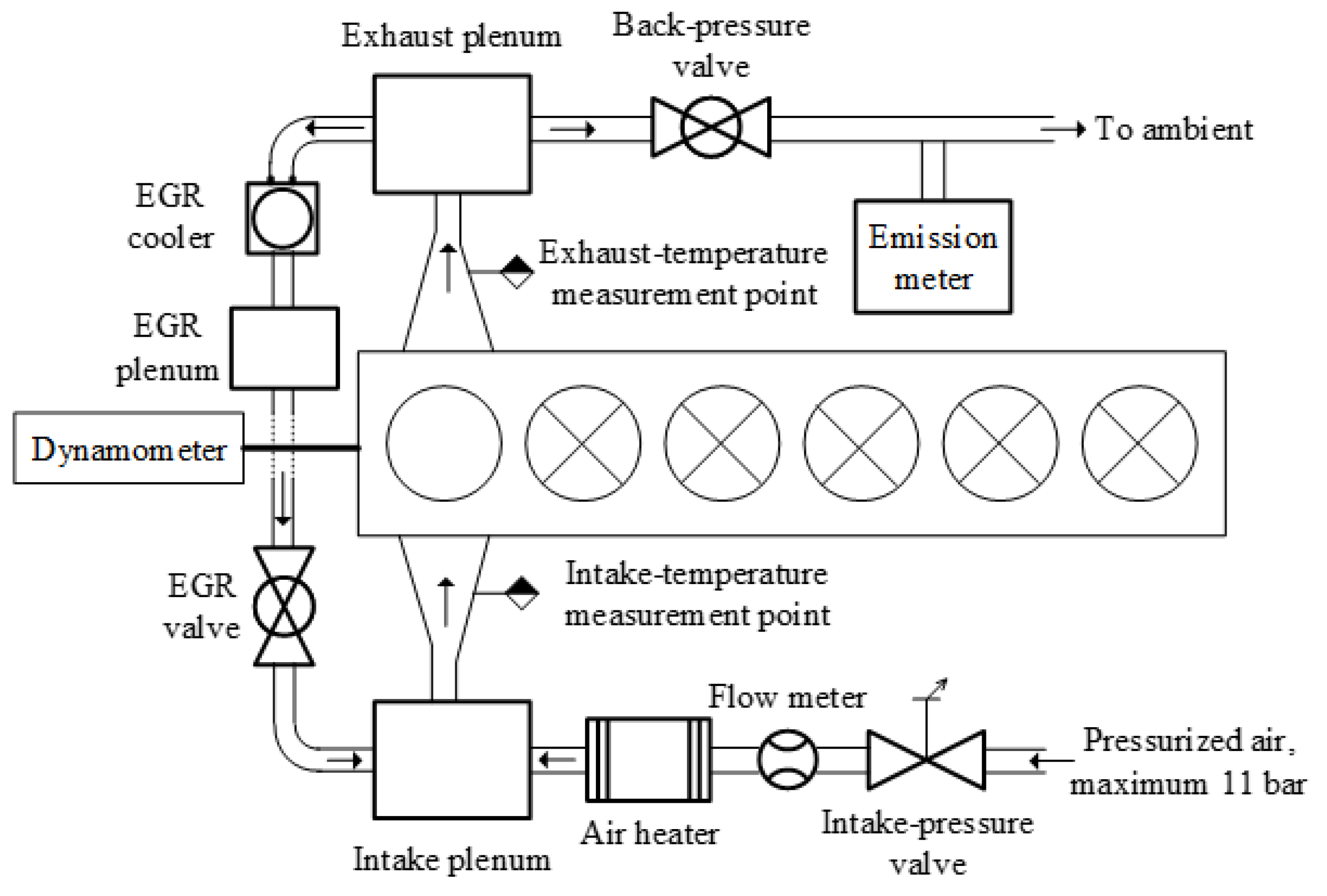
2.1. Test Cell Setup

The experiments were conducted on a four-stroke, six-cylinder Scania D13 heavy-duty direct-injection engine. For our experiments, the engine was modified to activate only one cylinder, with independently controlled intake, exhaust, and injection systems. The schematics can be seen in Figure 1. The engine speed was constant at 1200 rpm. This speed is often used in industrial settings because it balances mechanical stress and thermal efficiency, providing a stable platform for evaluating the impact of alternative fuels like methanol on engine performance and emissions. A stepped lip piston, seen in Figure 2b, was used with a compression ratio (CR) of 17.3:1. The four-stroke engine had a bore of 160 mm and a stroke of 130 mm. The exhaust valve opened (EVO) at 137 °CA aTDC, and the intake valve closed (IVC) at −141 °CA aTDC. A Scania XPI common rail injection system supplied a solenoid-type 12-hole injector with methanol. The equally spaced twelve holes had a diameter of 230 μ m and an included spray angle of 120°. Considering methanol’s low viscosity, high injection pressures can lead to instability in the common rail system’s pressure. This instability may cause issues within the injector nozzles, such as cavitation or premature wear, potentially impacting the accuracy of fuel delivery and affecting engine performance and longevity. Therefore, the injection pressure was set at 800 bar, and the injection duration was 840 μ s (approximately 6 crank-angle degrees, CADs), achieving a load of 4 bar IMEPg. Due to the changing SOI, the intake temperature was tuned to achieve combustion phasing of CA50 (CAD of 50% heat released) at 3 °CA aTDC, and no EGR was used. The intake air was 1 bar. Methanol, characterized by its high latent heat, absorbs considerable heat upon injection into the cylinder, reducing the in-cylinder temperature. To stabilize auto-ignition, the intake air was heated using an externally powered air heater to ensure that the CA50 reached 3 °CA aTDC in all cases. This process was regulated by a proportional-integral-derivative (PID) controller, achieving a temperature control accuracy of ±0.5 °C. Emission measurements, including NO, CO, unburned hydrocarbons (UHCs), and O2 concentrations, were carried out using a Horiba MEXA-7000 motor exhaust gas analyzer.
The in-cylinder pressure was measured using a water-cooled piezoelectric pressure transducer connected to the charge amplifier with sampling every 0.2 crank angle degree (CAD). The mean heat release rate (HRR) was calculated from the in-cylinder pressure across 300 cycles. To realize HCCI and PPC strategies, the SOI was swept from −100 °A aTDC to −15 °CA aTDC. In this study, the HCCI strategy ranged from −100 °A aTDC to −60 °CA aTDC, whereas the PPC strategy ranged from −60 °CA aTDC to −15 °CA aTDC.

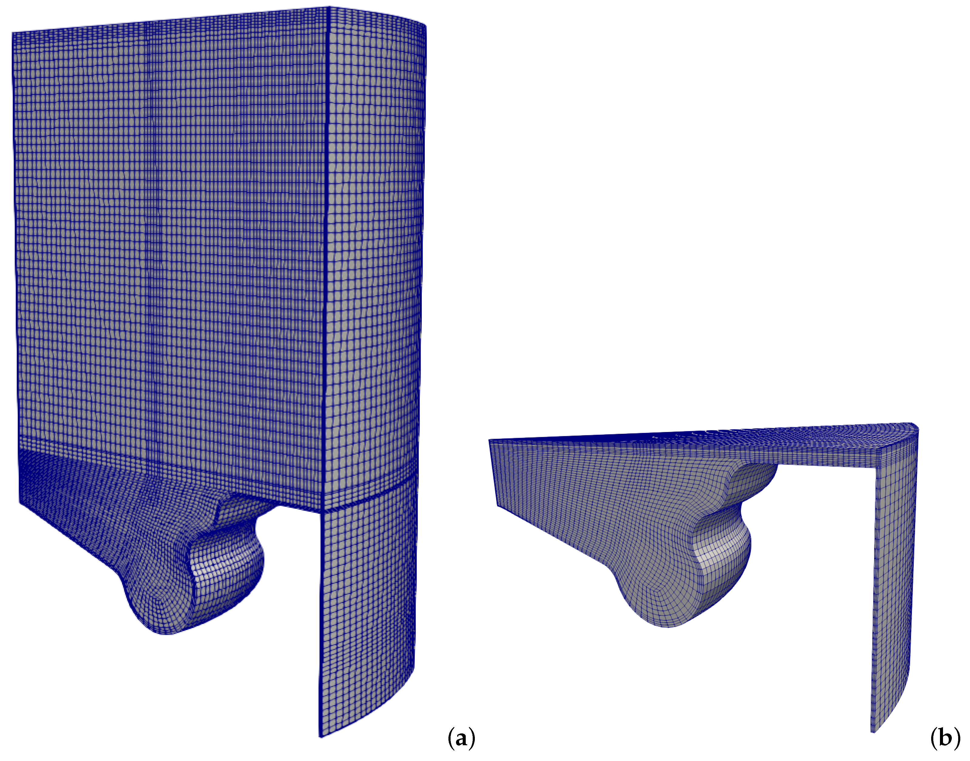
2.2. Simulation Setup

The numerical simulations were carried out using OpenFOAM 7. A 30° sector of the full cylinder was used as the computational domain, which was decided by the number of holes in the injector. The simulation was run from IVC (−141 °CA aTDC) to EVO (137 °CA aTDC). Figure 2a and Figure 2b show the mesh at −50 °CA aTDC and TDC, respectively. The mesh is shown at two crank angles to demonstrate the dynamic meshing algorithm [33], which adds and removes cells/layers above a specified region. As can be seen, when comparing the figures, the cells in the squish region do not become compressed as the piston approaches TDC.
This algorithm was implemented to prevent significantly compressed cells as the piston moves upward during the compression stroke, causing high cell aspect ratios and limitations from the Courant–Freidrich–Lewy (CFL) constraints. Similarly, the highly compressed cells in these regions can have problems with early injection timings as there is likely to be more fuel in these regions due to early injection. As a result of this algorithm, the cell count at IVC is 253,704, whereas, at TDC, the cell count is reduced to 64,944. It should be emphasized that none of the cells in the bowl or squish region are affected by the algorithm. For the wall treatment, the standard wall functions “kqRWallFunction” and “epsilonWallFunction” from OpenFOAM- V7 were utilized, which helped mitigate potential grid-induced anomalies in the turbulence near the wall. A mesh independence study was carried out using 121,000, 65,000, and 41,000 cells corresponding to a fine, medium, and coarse grid, respectively. The coarse grid overpredicted the maximum in-cylinder pressure and under-predicted the ignition delay time. The pressure trace and AHRR of the medium and fine grids showed very good agreement. Considering the computational benefits and comparable results, the medium grid was considered to be the most suitable. A summary of the models used for simulations is presented in Table 1. The simulations used the Reynolds-Averaged Navier–Stokes (RANS) framework. A modified generalized renormalization group (gRNG) k ϵ  [34] was used for the simulations where the model coefficients have also been modified to account for the variable density and to improve the capability of more accurately predicting the turbulent kinetic energy and length scale in compression/expansion flows. The injection profiles were modeled using the model of Xu et al. [35], and the spray was modeled using the Lagrangian–Eulerian approach. The KH-RT breakup model was implemented with specific parameters: B0 = 0.61, B1 = 20, Ctau = 1, and CRT = 0.1. The liquid droplets after injection were simulated using parcels with different initial diameters (2 million parcels per second), and the droplet size distribution was modeled using the Rosin–Rammler function. The maximum and minimum droplet diameters were set to 230 μ m and 2 μ m, respectively, 1 and 1/100 of the nozzle diameter, and the SMD of the initial droplets was 115 μ m.
The actual fuel injection in the simulations was shifted by 3 CAD to account for the delay between the engine’s electronic control unit (ECU) and the needle lift. During injection, the spray droplets undergo a primary breakup process where the Kelvin–Helmholtz (KH) model is responsible, and the Rayleigh–Taylor (RT) instability is responsible for the secondary breakup. To capture the full breakup process, the KH-RT model [36] was implemented. The evaporation was modeled using the Spalding [37] formula, and the fluid–particle heat transfer model of a single particle in hot gas flow was described by the Ranz–Marshall [38] correlation. The spray/wall interaction was simplified to stick/rebound. The skeletal reaction mechanism from Liu et al. [39] and the extended Zeldovich mechanism [40] (extended version taken from Ref. [41]) were used to calculate the instantaneous reaction rate as well as the formation and oxidation processes of emission species. The reaction mechanism of Liu et al. [39] includes 136 species and 617 reactions. The partially stirred reactor (PaSR) model is used for the turbulence chemistry interaction. Based on the experiment results of Andruskiewicz et al. [42], the cylinder wall and flat cylinder head had a temperature of 430 K, while the piston had a temperature of 450 K.

3. Results and Discussion

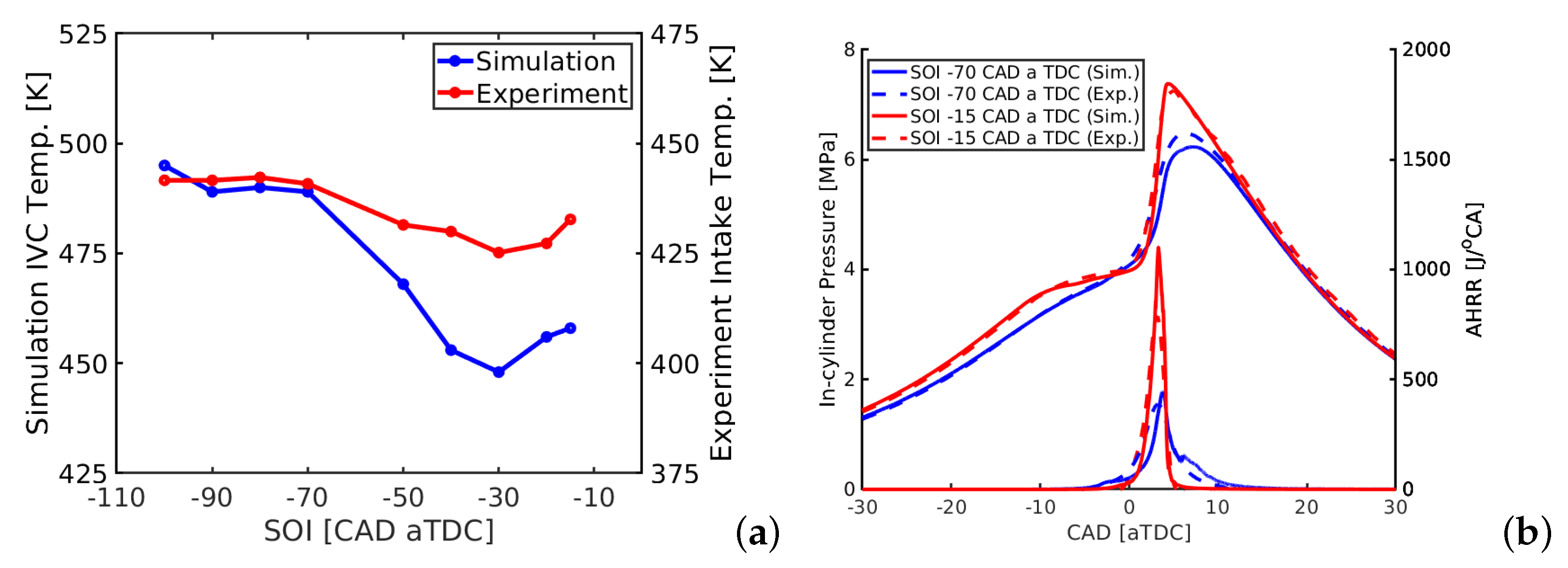
3.1. In-Cylinder Pressure and Heat Release Process

As previously mentioned, the intake temperature was adjusted to achieve CA50 at 3 °CA aTDC for all injection timings. The intake temperatures from the experiments did not directly translate to the simulations. As the simulations began at IVC (−141 °CA aTDC), the in-cylinder temperature is specified in the simulations rather than the intake temperature, which explains the discrepancies seen between the temperatures in Figure 3a. The experiments and the simulations predict the well-known intake temperature’s ’spoon shape’ profile. The ’spoon shape’ profile shows the highest intake temperatures during the HCCI phase (−100 °CA aTDC to −60 °CA aTDC. During this phase, the intake temperature does not significantly vary as the SOI changes, forming the spoon’s handle. As the SOI transitions into the PPC range, the intake temperature drops and rises as the SOI approaches TDC, forming the curved part of the spoon. The variation in intake temperature is due to the levels of composition and temperature stratification associated with the respective strategies. The HCCI achieves mostly homogeneous fuel-lean mixtures due to the long mixing time after injection, requiring high in-cylinder temperatures to ignite the mixture. PPC strategies, however, achieve more stratified mixtures where fuel-richer pockets are found in the combustion chamber, which can be ignited with less energy. However, with further retarded SOI, the fuel has less available time to be heated, evaporated, and mixed with the air. Thus, a high intake temperature is required to ignite a more stratified mixture.
Figure 3b shows the pressure trace and apparent heat release rate (AHRR) for SOI of −70 °CA aTDC (blue) and SOI of −15 °CA aTDC (red), where the simulation data is shown by the solid line and the experiment by the dashed line. These cases were compared against the experimental data as they represent the HCCI and PPC strategies. In both cases, the simulation can accurately predict the in-cylinder pressure trace and the AHRR. The in-cylinder pressure and AHRR are shown to be sensitive to the injection timing. The fundamental reason behind this was explored using the numerical data and is discussed below.

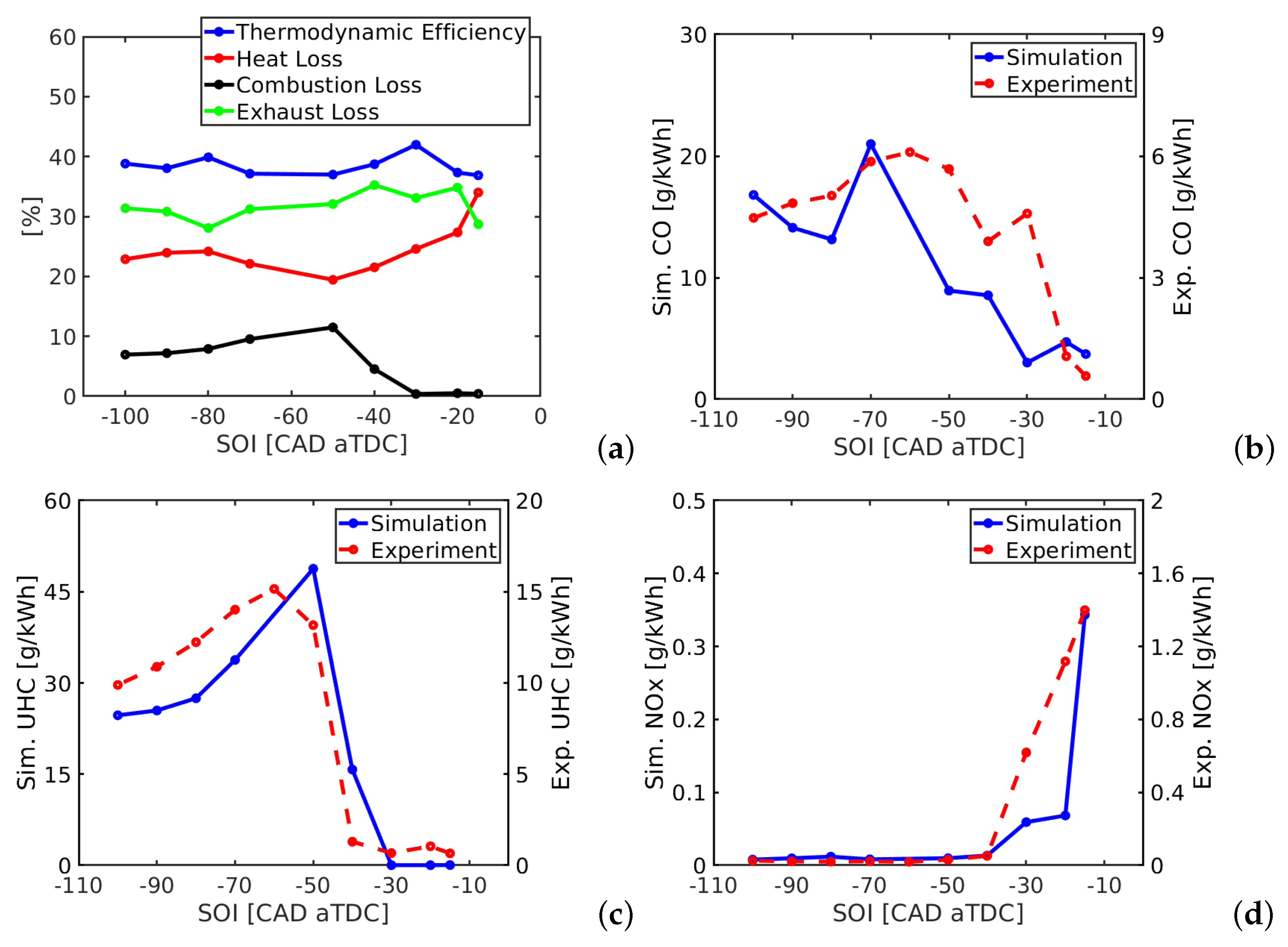
3.2. Engine Performance under HCCI and PPC Operation Conditions

The pressure trace and AHRR shown in Figure 3b represent the changing combustion duration as the SOI was retarded from the HCCI range into the PPC range. At SOI −70 °CA aTDC, the combustion duration was 8.29 CAD, the longest duration of all cases investigated. As a result of the long combustion duration, the MPRR and AHRR are lower. At SOI −15 °CA aTDC, the combustion duration is significantly reduced to 2.32 CAD, almost three times shorter than the earliest SOI case. To investigate why the combustion duration is significantly different, the fuel and temperature distribution at various CAD will be shown. Figure 4a and Figure 4b show the mass fraction of methanol at 10 CAD after the start of injection for the SOI −70 °CA aTDC and SOI −15 °CA aTDC cases, respectively. The impingement location for the HCCI case is on the chamber wall, just above the piston topland, allowing fuel to enter the crevice region easily. The late injection of the PPC case injects all the fuel into the bowl, where it cannot enter the crevice. This will affect the combustion efficiency and emissions of UHC and CO, since the fuel/air mixture in the crevice is difficult to combust due to the low temperature and wall quenching. This will be discussed further below.
Figure 5a and Figure 5c show, respectively, the distribution of fuel mass fraction immediately after the start of ignition for the HCCI case (SOI of −70 °CA aTDC) and the PPC case (SOI of −15 °CA aTDC), which shows a much fuel-leaner mixture in the HCCI case compared to the PPC case. The temperature distribution of the HCCI case, at the same crank angle, shows the ignition kernel in the mixture towards the center of the piston bowl and in the squish region, cf. Figure 5b. Following the spread of the high-temperature region at TDC in Figure 5f and at 3 CAD aTDC, a third ignition site can be found in the piston bowl, cf. Figure 5j. At 6 CAD aTDC, the HCCI case exhibits a fairly complete combustion and uniform temperature throughout the cylinder, except in regions close to the wall, cf. Figure 5m,n. The maximum temperature in the cylinder is about 1900 K. Fuel consumption is closely correlated with high-temperature regions, cf. Figure 5e,f and Figure 5i,j. One can estimate the propagation velocity of the reaction front, knowing the engine bore (160 mm). With two ignition fronts, each propagates through half of the bore, taking 9 CAD (1.25 ms). The propagating speed is about 30 m/s, which indicates that reaction fronts are propagating in ignition front mode rather than a premixed flame mode since the flame speed would be much lower.
The PPC case shows a high spatial stratification in the fuel mass fraction and temperature fields. Ignition starts in the fuel-lean high-temperature region, and the reaction front successively propagates into the fuel-richer mixtures. The fuel-richer mixtures have higher flame temperatures, and ignition front propagation is faster. As seen in Figure 5g,k, fuel-richer mixtures in a large region are combusted from 3 CAD to 6 CAD. This explains the higher AHRR in the PPC case, as shown in Figure 3b. The maximum flame temperature in the PPC case is higher than the HCCI case, cf. Figure 5j,l, which will result in higher NOx emissions in the PPC case, as discussed below.
Figure 6a shows the net work/thermodynamic efficiency, heat losses, and combustion losses across all of the cases in this investigation. The interaction between the spray and the wall/piston bowl is an important factor when investigating engine performance [43,44]. As discussed previously, during the HCCI cases, the spray interacts with the chamber wall rather than the piston. The stepped lip piston used in this investigation is designed to enhance mixing when the spray interacts with or close to the stepped lip. As discussed earlier, the HCCI methods inject fuel early during the compression stroke, such that the spray interacts with the wall of the combustion chamber, as seen in Figure 4a. In this figure, the spray is directly targeted towards the crevice, and, as a result, the fuel becomes trapped and remains untouched. The combustion losses are attributed to the trapped fuel that cannot be burned during the combustion process, cf. Figure 5m,o. As seen in Figure 6a, the combustion losses increase as the spray impingement occurs closer to the piston topland with retarding SOI. When the spray is targeted in the piston bowl, the combustion efficiency increases (low combustion losses), which occurs after SOI −50 °CA aTDC. The late PPC cases have the highest combustion efficiency, as the spray interacts deep in the bowl, as previously discussed and shown in Figure 5.
The heat losses are relatively higher in the HCCI cases with earlier SOI due to the uniform temperature in the cylinder and, thus, near-wall combustion, cf. Figure 5n. The heat losses are the highest for the late SOI PPC cases due to the higher combustion temperature in the cylinder, cf. Figure 5p. As the fuel pocket fully ignites near the piston surface, a significant amount of heat is lost to the piston surface close to the stepped lip. The HCCI case with SOI −70 °CA aTDC also shows the combustion occurring near the walls; however, the combustion temperature is significantly lower than that of the PPC case, and, as a result, the heat losses are significantly lower than the PPC case.
The thermodynamic efficiency, or the net work, is the percentage of energy from the fuel that has been converted to energy acting on the piston, which can be calculated as:
η = I V C E V O P d V m f Q L H V
where m f is the injected fuel mass for one cycle and Q L H V is the lower heating value of methanol. As observed by the thermodynamic efficiency trend, there is a significant trade-off between the combustion, heat, and exhaust losses. A peak in thermodynamic efficiency is seen at SOI −80 °CA aTDC, and a more significant peak at SOI −30 °CA aTDC, where the exhaust losses, or unused thermal energy, is low compared to the surrounding SOIs. The increase in exhaust losses is due to the increasing combustion temperatures as a result of the fuel-richer mixtures; however, at SOI −30 °CA aTDC, the exhaust losses see a drop as a result of the low intake temperature in Figure 3a. The combination of lower exhaust loss and extremely low combustion loss overcome the slightly higher heat losses.

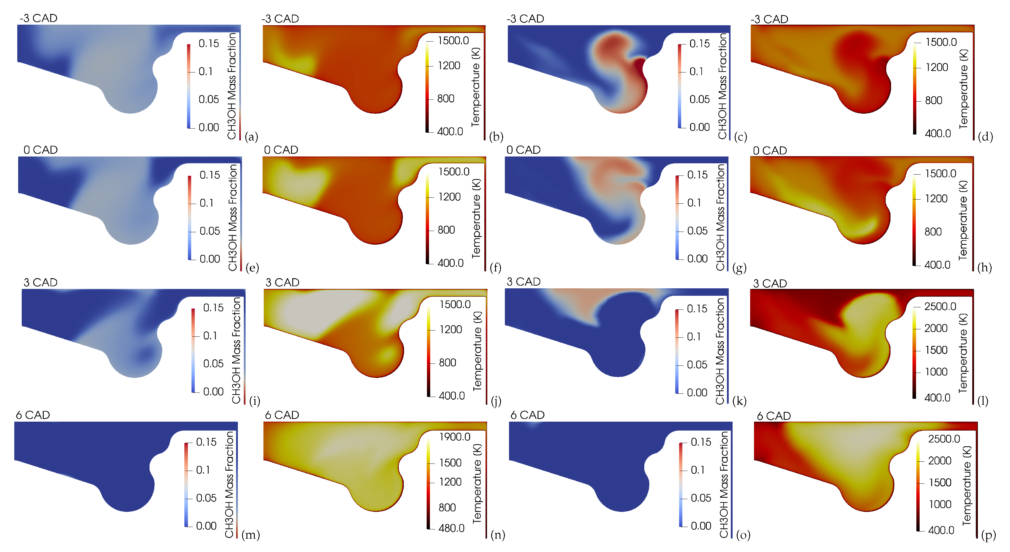
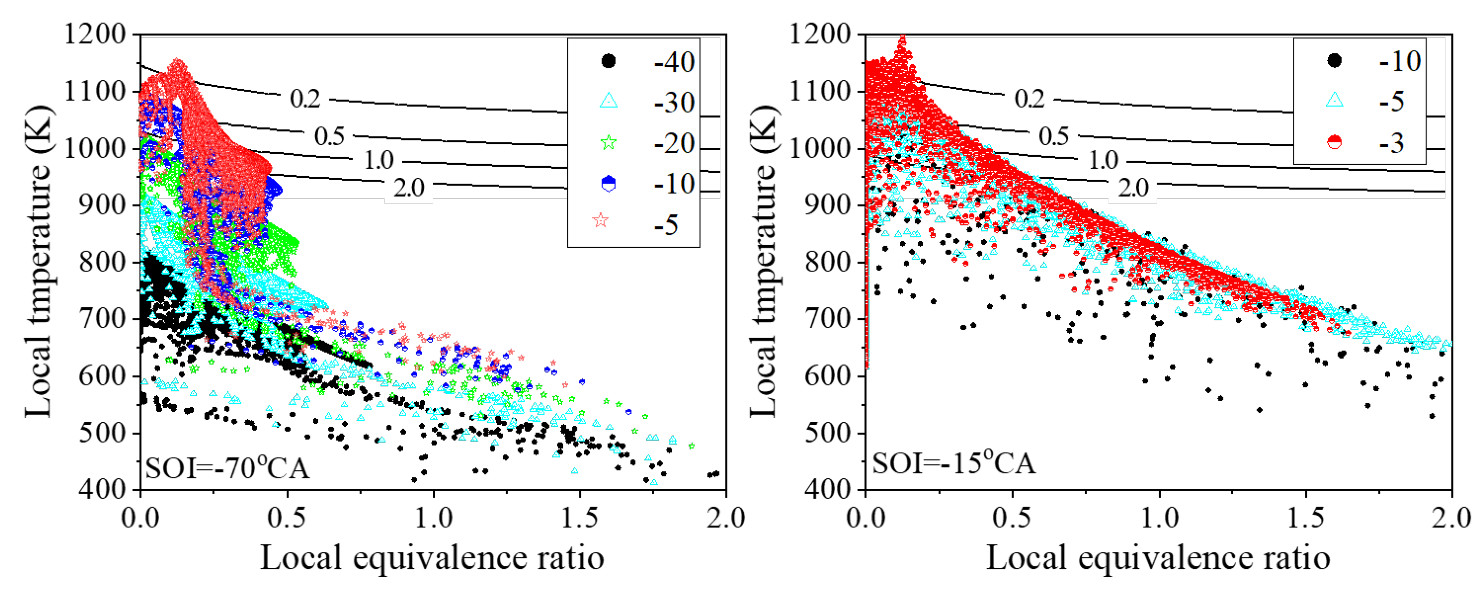
3.3. Combustion Characteristics

Figure 7 shows the local equivalence ratio ( ϕ ) and temperature (T) of the mixture in the cylinder at different CADs for the HCCI and the PPC cases. The results are presented in the T ϕ space. Also shown in the figure are the iso-lines of ignition delay time at a range of initial temperature of equivalence ratio. In general, for the same initial temperature, a fuel-richer mixture has a shorter ignition delay time. For the same equivalence ratio, a higher initial temperature has a shorter ignition dealt time. The onset of ignition in the engine depends on both temperature and local equivalence ratio. Before the onset of ignition, the mixture in the cylinder shows a monotonic decrease of ϕ with T. For the HCCI case, at −5 CAD, this monotonic profile of T ϕ is a violated indication of the onset of ignition at this time. The peak temperature location shows that the ignition is at ϕ 0.2 . Methanol has a heat of vaporization approximately four times higher than gasoline or diesel. Therefore, during the injection phase, the liquid spray absorbs a significant amount of heat, which is then absorbed in the evaporation phase. As a result, ignition does not occur in the fuel-rich regions as the fuel regions are cooled during evaporation.
A similar trend can be seen in the PPC case, where the ignition kernel appears to occur in the fuel-leaner region with ϕ 0.2 , at −3 CAD. This fuel-lean ignition region is in the mixing layer between the entraining air and the spray, cf. Figure 5d. The high-temperature reaction front follows the direction of the spray, following the fuel pocket into the bowl and up towards the stepped lip portion of the piston, cf. Figure 5h. As the high-temperature reaction front is following the fuel pocket, a sudden ignition of the fuel pocket is seen in Figure 5h, which can be attributed to the rapid heat release rate and higher MPRR seen in Figure 3b. The high-temperature reaction front continues towards the remainder of the fuel, completing combustion. The momentum of the flame towards the fuel pocket causes the fuel to combust rapidly, whereas, in the HCCI phase, the fuel-richer region is the last to burn as there is no such momentum. The estimated reaction front propagation speed in the PPC case is about 60 m/s for the combustion of the fuel-richer pocket from TDC to 3 CAD aTDC (cf. Figure 5d,h). At 6 CAD aTDC, the PPC case has also been completed, with a maximum temperature of about 2500 K in the cylinder. The temperature near the wall of the piston bowl is, however, significantly lower. In the HCCI and PPC cases, a small amount of fuel remains in the chamber after combustion. The HCCI case has fuel in the crevice (Figure 5m) and the PPC case a small amount of fuel close to the cylinder head at the center of the chamber (Figure 5o).

3.4. Engine-Out Emissions

The engine-out emissions of CO obtained from the experiments can be seen in Figure 6b. Large amounts of CO are formed during the combustion process; however, typically, it is oxidized to CO2 during the combustion process. To oxidize the CO, sufficient level of oxygen and OH radicals in temperatures above 1500 K [45] are required. Typically, CO is not oxidized in the later stages of the combustion process, as, during this phase, fuel-lean regions struggle to meet the requirements for high temperatures. The simulation data show good agreement with the experimental trend of CO formation. Higher levels of CO are observed in the HCCI range of mixture formation before a steep drop occurs during the PPC range. The formation of the mixture is critical for oxidizing CO. As was mentioned earlier, each of the cases exhibited the start of ignition in regions of approximately ϕ = 0.2 . For the PPC range, this is beneficial as, typically, the fuel-lean regions are harder to ignite; therefore, when the fuel-lean regions ignite first, the high-temperature reaction front is more easily spread to the fuel-richer regions, which are easier to ignite. This leads to more complete oxidation of the CO. For the HCCI case, the equivalence ratio is much more globally lean, meaning that the reaction front is more difficult to propagate after ignition, especially considering that a portion of the fuel is trapped in the crevice region. Another aspect that contributes to the oxidation of CO is the combustion duration. The heat release rate of a HCCI case and PPC case in Figure 3b shows that the combustion duration is significantly shorter for the PPC case, and, as such, is a more complete combustion of the fuel and CO.
UHC emissions are caused by incomplete combustion where the entirety of the fuel is not burned; therefore, the combustion losses in Figure 6a follow a similar trend to the UHC emissions, as shown in Figure 6c. As explained earlier, the early injection of HCCI increases the possibility of fuel being trapped in the crevice region, which is observed in the trend for both combustion efficiency and UHC emissions. Naturally, this fuel is separated from the high-temperature regions in the main piston bowl. The peak UHC emissions are observed in the SOI case at −40 °CA aTDC, where the spray is targeted towards the crevice and a large amount of fuel is trapped. As the SOI is retarded, the fuel spray is gradually targeted toward the piston topland. At SOIs −50 °CA aTDC, the spray directly interacts with the piston topland, meaning that the highest mass of fuel of all cases becomes trapped in the crevice region, leading to the peak of UHC emissions and combustion losses. After this SOI, the UHC emissions drop drastically as the spray is directed in the piston bowl, so the fuel can no longer enter the crevice.
The formation of NOx is controlled by the Zeldovich mechanism in which NOx forms in temperatures over 1800 K. LTC concepts intend on keeping combusting temperatures low to prevent high levels of NOx emissions, which is clear in Figure 6d. Low combustion temperatures are achieved by fuel-lean mixture formation, and methanol can particularly be suitable for LTC, since the onset of methanol ignition is typically in fuel-lean regions. The numerical simulations can predict the experimental data well; however, the increase in NOx emissions at SOI −15 °CA aTDC is under-predicted by the simulation. The dramatic increase in NOx emissions occurs in the late PPC range, where greater levels of stratification are found with larger fuel-rich regions. The fuel-rich regions burn at temperatures as high as 2500 K and, hence, form NOx, cf. Figure 5p.

4. Conclusions

Numerical simulations of methanol in a heavy-duty compression-ignition low-temperature combustion engine were carried out across various SOIs, realizing HCCI and PPC concepts. The purpose of this study was to investigate the engine performance and emissions of a compression-ignition engine fueled with methanol in HCCI to PPC conditions. The intake temperature was adjusted to maintain the same combusting phasing for all cases. The simulation agreed with the pressure trace and apparent heat release rate measured in the experiments.
The simulation predicted the ’spoon shape’ profile for methanol intake temperatures. The early PPC SOIs required the lowest intake temperatures due to the good mixture stratification. The combustion duration was shorter in the PPC range due to the increased mixture stratification and fuel-rich regions, which led to an increased pressure rise rate compared to HCCI cases. The case with the highest thermodynamic efficiency was at SOI −30 °CA aTDC with 41.96%. SOI −80 °CA aTDC achieved the highest thermodynamic efficiency during the HCCI phase with 39.87%. The heat losses increased as the SOI was retarded due to the onset of ignition occurring near the piston floor and spreading deeper into the piston bowl, losing heat to the surface. Combustion losses were highest during the HCCI phase as fuel became trapped in the crevice region due to early injection. Combustion efficiency was lowest at SOI −50 °CA aTDC when the spray was directed toward the topland and crevice. The onset of ignition was consistently seen in fuel-lean regions due to fuel-rich regions having lower temperatures due to the high vaporization of the heat value of methanol. The simulation was able to predict the trend of emission from the experimental measurements, however, overall, under-predicted the values. CO decreased with retarded SOI due to the greater level of oxidation from the more stratified mixtures found in PPC. The UHC emissions were proportional to the fuel trapped in the crevice region and the combustion efficiency with the same trend observed. The NOx emissions remained extremely low during the HCCI phase until SOI −40 °CA aTDC, where the fuel-rich regions burned at higher temperatures, causing NOx formation.

Author Contributions

Conceptualization, X.-S.B.; Methodology, M.T., L.X., H.F. and X.-S.B.; Software, M.T. and L.X.; Validation, M.T. and L.X.; Formal analysis, M.T., L.X., H.F., O.K. and X.-S.B.; Investigation, M.T., L.X. and O.K.; Writing – original draft, M.T.; Writing – review & editing, L.X., H.F., O.K. and X.-S.B.; Funding acquisition, X.-S.B. All authors have read and agreed to the published version of the manuscript.

Funding

This work was supported by the Swedish Research Council (VR) and Swedish Energy Agency (STEM) through the Competence Centre for the Combustion Processes (KCFP) at Lund University. The computations were enabled by resources provided by the National Academic Infrastructure for Supercomputing in Sweden (NAISS), partially funded by the Swedish Research Council through grant agreement no. 2022-06725.

Data Availability Statement

The data presented in this study are available on request from the corresponding author.

Conflicts of Interest

The authors declare no conflicts of interest.

Abbreviations

The following abbreviations are used in this manuscript:
AHRRApparent heat release rate
CADCrank angle degree
HCCIHomogeneous charge compression ignition
HRRHeat release rate
LTCLow-temperature combustion
PPCPartially premixed combustion
SOIStart of injection
TDCTop dead center
UHCsUnburned hydrocarbons
°CA aTDCCrank-angle degree after TDC

References

  1. Reitz, R.D.; Ogawa, H.; Payri, R.; Fansler, T.; Kokjohn, S.; Moriyoshi, Y.; Zhao, H.; Arcoumanis, D.; Assanis, D.; Bae, C.; et al. IJER editorial: The future of the internal combustion engine. Int. J. Engine Res. 2020, 21, 3–10. [Google Scholar] [CrossRef]
  2. Milojević, S.; Glišović, J.; Savić, S.; Bošković, G.; Bukvić, M.; Stojanović, B. Particulate Matter Emission and Air Pollution Reduction by Applying Variable Systems in Tribologically Optimized Diesel Engines for Vehicles in Road Traffic. Atmosphere 2024, 15, 184. [Google Scholar] [CrossRef]
  3. Yip, H.L.; Srna, A.; Yuen, A.C.Y.; Kook, S.; Taylor, R.A.; Yeoh, G.H.; Medwell, P.R.; Chan, Q.N. A review of hydrogen direct injection for internal combustion engines: Towards carbon-free combustion. Appl. Sci. 2019, 9, 4842. [Google Scholar] [CrossRef]
  4. Verhelst, S.; Turner, J.W.; Sileghem, L.; Vancoillie, J. Methanol as a fuel for internal combustion engines. Prog. Energy Combust. Sci. 2019, 70, 43–88. [Google Scholar] [CrossRef]
  5. Xu, L.; Xu, S.; Bai, X.S.; Repo, J.A.; Hautala, S.; Hyvönen, J. Performance and emission characteristics of an ammonia/diesel dual-fuel marine engine. Renew. Sustain. Energy Rev. 2023, 185, 113631. [Google Scholar] [CrossRef]
  6. Kaario, O.T.; Karimkashi, S.; Bhattacharya, A.; Vuorinen, V.; Larmi, M.; Bai, X.S. A comparative study on methanol and n-dodecane spray flames using Large-Eddy Simulation. Combust. Flame 2024, 260, 113277. [Google Scholar] [CrossRef]
  7. Bao, J.; Wang, H.; Wang, R.; Wang, Q.; Di, L.; Shi, C. Comparative experimental study on macroscopic spray characteristics of various oxygenated diesel fuels. Energy Sci. Eng. 2023, 11, 1579–1588. [Google Scholar] [CrossRef]
  8. Shi, C.; Chai, S.; Wang, H.; Ji, C.; Ge, Y.; Di, L. An insight into direct water injection applied on the hydrogen-enriched rotary engine. Fuel 2023, 339, 127352. [Google Scholar] [CrossRef]
  9. Milojević, S.; Savić, S.; Marić, D.; Stopka, O.; Krstić, B.; Stojanović, B. Correlation between emission and combustion characteristics with the compression ratio and fuel injection timing in tribologically optimized diesel engine. Teh. Vjesn. 2022, 29, 1210–1219. [Google Scholar]
  10. Tian, Z.; Wang, Y.; Zhen, X.; Liu, Z. The effect of methanol production and application in internal combustion engines on emissions in the context of carbon neutrality: A review. Fuel 2022, 320, 123902. [Google Scholar] [CrossRef]
  11. Agarwal, A.K.; Singh, A.P.; Maurya, R.K. Evolution, challenges and path forward for low temperature combustion engines. Prog. Energy Combust. Sci. 2017, 61, 1–56. [Google Scholar] [CrossRef]
  12. Pachiannan, T.; Zhong, W.; Rajkumar, S.; He, Z.; Leng, X.; Wang, Q. A literature review of fuel effects on performance and emission characteristics of low-temperature combustion strategies. Appl. Energy 2019, 251, 113380. [Google Scholar] [CrossRef]
  13. Lachaux, T.; Musculus, M.P. In-cylinder unburned hydrocarbon visualization during low-temperature compression-ignition engine combustion using formaldehyde PLIF. Proc. Combust. Inst. 2007, 31, 2921–2929. [Google Scholar] [CrossRef]
  14. Yao, M.; Zheng, Z.; Liu, H. Progress and recent trends in homogeneous charge compression ignition (HCCI) engines. Prog. Energy Combust. Sci. 2009, 35, 398–437. [Google Scholar] [CrossRef]
  15. Sharma, T.K.; Rao, G.A.P.; Murthy, K.M. Homogeneous Charge Compression Ignition (HCCI) Engines: A Review. Arch. Comput. Methods Eng. 2016, 23, 623–657. [Google Scholar] [CrossRef]
  16. Noehre, C.; Andersson, M.; Johansson, B.; Hultqvist, A. Characterization of Partially Premixed Combustion. SAE Technical Paper 2006-01-3412. 2006. Available online: https://www.sae.org/publications/technical-papers/content/2006-01-3412/ (accessed on 14 August 2024).
  17. Kalghatgi, G.T.; Risberg, P.; Ångström, H.E. Partially Pre-Mixed Auto-Ignition of Gasoline to Attain Low Smoke and Low NOx at High Load in a Compression Ignition Engine and Comparison with a Diesel Fuel. SAE Technical Paper 2007-01-0006. 2007. Available online: https://www.sae.org/publications/technical-papers/content/2007-01-0006/ (accessed on 14 August 2024).
  18. Manente, V.; Johansson, B.; Tunestal, P. Partially Premixed Combustion at High Load using Gasoline and Ethanol, a Comparison with Diesel. SAE Technical Paper 2009-01-0944. 2009. Available online: https://www.sae.org/publications/technical-papers/content/2009-01-0944/ (accessed on 14 August 2024).
  19. Reitz, R.D.; Duraisamy, G. Review of high efficiency and clean reactivity controlled compression ignition (RCCI) combustion in internal combustion engines. Prog. Energy Combust. Sci. 2015, 46, 12–71. [Google Scholar] [CrossRef]
  20. Shen, M.; Tuner, M.; Johansson, B.; Cannella, W. Effects of EGR and Intake Pressure on PPC of Conventional Diesel, Gasoline and Ethanol in a Heavy Duty Diesel Engine. SAE Technical Paper 2013-01-2702. 2013. Available online: https://www.sae.org/publications/technical-papers/content/2013-01-2702/ (accessed on 14 August 2024).
  21. Ravaglioli, V.; Ponti, F.; Silvagni, G.; Moro, D.; Stola, F.; De Cesare, M. Performance Assessment of Gasoline PPC in a Light-Duty CI Engine. SAE Technical Paper 2022-01-0456. 2022. Available online: https://www.sae.org/publications/technical-papers/content/2022-01-0456/ (accessed on 14 August 2024).
  22. Li, C.; Yin, L.; Shamun, S.; Tuner, M.; Johansson, B.; Solsjo, R.; Bai, X.-S. Transition from HCCI to PPC: The Sensitivity of Combustion Phasing to the Intake Temperature and the Injection Timing with and without EGR. SAE Technical Paper 2016-01-0767. 2016. Available online: https://www.sae.org/publications/technical-papers/content/2016-01-0767/ (accessed on 14 August 2024).
  23. Svensson, M.; Tuner, M.; Verhelst, S. Low Load Ignitability of Methanol in a Heavy-Duty Compression Ignition Engine. SAE Technical Paper 2022-01-1093. 2022. Available online: https://www.sae.org/publications/technical-papers/content/2022-01-1093/ (accessed on 14 August 2024).
  24. Zincir, B.; Shukla, P.; Shamun, S.; Tuner, M.; Deniz, C.; Johansson, B. Investigation of Effects of Intake Temperature on Low Load Limitations of Methanol Partially Premixed Combustion. Energy Fuels 2019, 33, 5695–5709. [Google Scholar] [CrossRef]
  25. Svensson, E.; Verhelst, S. Numerical Optimization of Compression Ratio for a PPC Engine Running on Methanol. SAE Technical Paper 2019-01-2168. 2019. Available online: https://www.sae.org/publications/technical-papers/content/2019-01-2168/ (accessed on 14 August 2024).
  26. Johansson, B.; Shamun, S.; Shen, M.; Tuner, M.; Pagels, J.; Gudmundsson, A.; Tunestal, P. Exhaust PM Emissions Analysis of Alcohol Fueled Heavy-Duty Engine Utilizing PPC. SAE Int. J. Engines 2016, 9, 2142–2152. [Google Scholar]
  27. Svensson, E.; Li, C.; Shamun, S.; Johansson, B.; Tuner, M.; Perlman, C.; Lehtiniemi, H.; Mauss, F. Potential Levels of Soot, NOx, HC and CO for Methanol Combustion. SAE Technical Paper 2016-01-0887. 2016. Available online: https://www.sae.org/publications/technical-papers/content/2016-01-0887/ (accessed on 14 August 2024).
  28. Pucilowski, M.; Jangi, M.; Shamun, S.; Li, C.; Tuner, M.; Bai, X.S. Effect of Start of Injection on the Combustion Characteristics in a Heavy-Duty DICI Engine Running on Methanol. SAE Technical Paper 2017-01-0560. 2017. Available online: https://www.sae.org/publications/technical-papers/content/2017-01-0560/ (accessed on 14 August 2024).
  29. Matamis, A.; Lonn, S.; Luise, L.; Vaglieco, B.M.; Tuner, M.; Andersson, O.; Alden, M.; Richter, M. Optical characterization of methanol compression-ignition combustion in a heavy-duty engine. Proc. Combust. Inst. 2021, 38, 5509–5517. [Google Scholar] [CrossRef]
  30. Xu, L.; Treacy, M.; Zhang, Y.; Aziz, A.; Tuner, M.; Bai, X.S. Comparison of efficiency and emission characteristics in a direct-injection compression ignition engine fuelled with iso-octane and methanol under low temperature combustion conditions. Appl. Energy 2022, 312, 118714. [Google Scholar] [CrossRef]
  31. Aziz, A.; Xu, L.; Garcia, A.; Tuner, M. Influence of Injection Timing on Equivalence Ratio Stratification of Methanol and Isooctane in a Heavy-Duty Compression Ignition Engine. SAE Technical Paper 2020-01-2069. 2020. Available online: https://www.sae.org/publications/technical-papers/content/2020-01-2069/ (accessed on 14 August 2024).
  32. Svensson, M.; Tuner, M.; Verhelst, S. Experimental Investigation of Pilot Injection Strategies to Aid Low Load Compression Ignition of Neat Methanol. SAE Technical Paper 2024-01-2119. 2024. Available online: https://www.sae.org/publications/technical-papers/content/2024-01-2119/ (accessed on 14 August 2024).
  33. Lucchini, T.; D’Errico, G.; Jasak, H.; Tukovic, Z. Automatic Mesh Motion with Topological Changes for Engine Simulation. SAE Technical Paper 2007-01-0170. 2007. Available online: https://www.sae.org/publications/technical-papers/content/2007-01-0170/ (accessed on 14 August 2024).
  34. Wang, B.L.; Lee, C.W.; Reitz, R.D.; Miles, P.C.; Han, Z. A generalized renormalization group turbulence model and its application to a light-duty diesel engine operating in a low-temperature combustion regime. Int. J. Engine Res. 2013, 14, 279–292. [Google Scholar] [CrossRef]
  35. Xu, L.; Bai, X.S.; Jia, M.; Qian, Y.; Qiao, X.; Lu, X. Experimental and modeling study of liquid fuel injection and combustion in diesel engines with a common rail injection system. Appl. Energy 2018, 230, 287–304. [Google Scholar] [CrossRef]
  36. Beale, J.C.; Reitz, R.D. Modeling spray atomization with the Kelvin-Helmholtz/Rayleigh-Taylor hybrid model. At. Spray 1999, 9, 623–650. [Google Scholar]
  37. Spalding, D.B. The combustion of liquid fuels. Symp. (Int.) Combust. 1953, 4, 847–864. [Google Scholar] [CrossRef]
  38. Ranz, W.; Marshall, W.R. Evaporation from drops: Part 2. Chem. Eng. Prog. 1952, 48, 173–180. [Google Scholar]
  39. Liu, X.; Wang, H.; Wei, L.; Liu, J.; Reitz, R.D.; Yao, M. Development of a reduced toluene reference fuel (TRF)-2, 5-dimethylfuran-polycyclic aromatic hydrocarbon (PAH) mechanism for engine applications. Combust. Flame 2016, 165, 453–465. [Google Scholar] [CrossRef]
  40. Zeldovich, Y.B. The oxidation of nitrogen in combustion and explosions. J. Acta Physicochimica 1946, 21, 577. [Google Scholar]
  41. Glarborg, P.; Miller, J.A.; Ruscic, B.; Klippenstein, S.J. Modeling nitrogen chemistry in combustion. Prog. Energy Combust. Sci 2018, 67, 31–68. [Google Scholar] [CrossRef]
  42. Andruskiewicz, P.; Najt, P.; Durrett, R.; Biesboer, S.; Schaedler, T.; Payri, R. Analysis of the effects of wall temperature swing on reciprocating internal combustion engine processes. Int. J. Engine Res. 2018, 19, 461–473. [Google Scholar] [CrossRef]
  43. Li, C.; Xu, L.; Bai, X.S.; Tunestal, P.; Tuner, M. Effect of Piston Geometry on Stratification Formation in the Transition from HCCI to PPC. SAE Technical Paper 2018-01-1800. 2018. Available online: https://www.sae.org/publications/technical-papers/content/2018-01-1800/ (accessed on 14 August 2024).
  44. Xu, L.; Bai, X.S.; Li, Y.; Treacy, M.; Li, C.; Tunestål, P.; Tunér, M.; Lu, X. Effect of piston bowl geometry and compression ratio on in-cylinder combustion and engine performance in a gasoline direct-injection compression ignition engine under different injection conditions. Appl. Energy 2020, 280, 115920. [Google Scholar] [CrossRef]
  45. Kim, D.; Ekoto, I.; Colban, W.F.; Miles, P.C. In-cylinder CO and UHC Imaging in a Light-Duty Diesel Engine during PPCI Low-Temperature Combustion. SAE Int. J. Fuels Lubr. 2008, 1, 933–956. [Google Scholar] [CrossRef]
Figure 1. Schematic of the engine used in the experiments.
Energies 17 04307 g001
Figure 2. (a) The mesh at −50 °CA aTDC. (b) The mesh at TDC.
Energies 17 04307 g002
Figure 3. (a) The initial temperature at IVC and the experimental intake temperature required to achieve a constant CA50 of 3 °CA aTDC. (b) The numerical and experimental in-cylinder pressure trace and apparent heat release rate (AHRR) for SOI of −70 °CA aTDC (blue) and −15 °CA aTDC (red) where the dashed line is the experimental data.
Energies 17 04307 g003
Figure 4. Distribution of methanol mass fraction on a plane through the spray axis in the cylinder, 10 CAD after the start of injection (aSOI). (a) HCCI case with SOI of −70 °CA aTDC, (b) PPC case with SOI of −15 °CA aTDC.
Energies 17 04307 g004
Figure 5. Distribution of methanol mass fraction and temperature on a plane through the spray axis in the cylinder during the earlier combustion phase. First and second panels from left: HCCI case with SOI of −70 °CA aTDC; third and fourth panels from the left: PPC case with SOI of −15 °CA aTDC.
Energies 17 04307 g005
Figure 6. (a) The net work/thermodynamic efficiency, heat, exhaust, and combustion losses for all cases investigated. (b) The numerical and experimental measurements of carbon monoxide (CO) emissions across the range of SOIs. (c) The numerical and experimental measurements of unburned hydrocarbon (UHC) emissions across the range of SOIs. (d) The numerical and experimental measurements of nitrogen oxides (NOx) emissions across the range of SOIs.
Energies 17 04307 g006
Figure 7. Local equivalence ratio and temperature distribution at the different crank angles. The iso-lines show the ignition delay times for homogeneous mixtures of methanol/air in a range of temperatures (900∼1200 K) and equivalence ratios (0.2∼2) simulated by the software Chemkin 18.0 with the same chemical kinetic mechanism as the 3D simulation used. The unit of IDT is ms.
Energies 17 04307 g007
Table 1. Numerical models used in the simulations.
PropertyModel Name
Turbulence ModelgRNG k ϵ
Injection ProfilesXu et al.
Spray BreakupKH-RT model
Reaction MechanismLiu et al. and extended Zeldovich
Evaporation ModelSpalding
Spray/Wall InteractionStick/rebound
Heat TransferRanz–Marshall correlations
Turbulence Chemistry InteractionPartially stirred reactor (PaSR)
Disclaimer/Publisher’s Note: The statements, opinions and data contained in all publications are solely those of the individual author(s) and contributor(s) and not of MDPI and/or the editor(s). MDPI and/or the editor(s) disclaim responsibility for any injury to people or property resulting from any ideas, methods, instructions or products referred to in the content.

