Article

Convection Heat Transfer and Performance Analysis of a Triply Periodic Minimal Surface (TPMS) for a Novel Heat Exchanger

by
Mohamad Ziad Saghir
* and
Mohammad Yahya
Department of Mechanical and Industrial Engineering, Toronto Metropolitan University, Toronto, ON M5B 2K3, Canada
*
Author to whom correspondence should be addressed.
Energies 2024, 17(17), 4275; https://doi.org/10.3390/en17174275
Submission received: 20 July 2024 / Revised: 20 August 2024 / Accepted: 24 August 2024 / Published: 27 August 2024
(This article belongs to the Section J1: Heat and Mass Transfer)

Abstract

Heat exchangers are necessary in most engineering systems that move thermal energy from a hot source to a colder location. The development of additive manufacturing technology facilitates the design and optimization of heat exchangers by introducing triply periodic minimal surface (TPMS) structures. TPMSs have shown excellent mechanical and thermal performance, which can improve heat energy transfer efficiency in heat exchangers. This current study intends to design and develop efficient, lightweight heat exchangers for aerospace and space applications. Using the TPMS structure, a porous construction encloses a horizontal tube that circulates heated fluid. Low-temperature water circulates inside a rectangular box that houses the complete system to remove heat from the horizontal pipe. Three porous structures, the gyroid, diamond, and FKS structures, were employed and examined. Porous models with various porosities and surface areas (15 cm2 and 24 cm2) were investigated. The results revealed that the gyroid structure exhibits the highest Nusselt number for heat removal (Nu max = 2250), confirming the highest heat transfer and lowest pressure drop among the three structures under investigation. The maximum Nusselt number obtained for the FKS structure is less than 1000, whereas, for the diamond structure, it is near 1250. A linear variation in the average Nusselt number as a function of the structure surface area was found for the FKS and diamond structures. In contrast, nonlinearity was observed in the gyroid structures.

1. Introduction

A heat exchanger is an essential device in most engineering systems that transfers thermal energy from a hot source to another location at a different temperature. Most heat exchanger designs are discrete, allowing heat transfer between the two fluids while preventing them from mixing. Heat exchangers are usually made of metals with high thermal conductivity, including copper, aluminum, or thin steel sheets, to facilitate energy transmission between the fluids. Various designs of heat exchangers have been developed in the literature [1,2,3,4] to improve the heat transfer between the hot inlet and cold outlet fluids, with studies conducted on numerical and experimental simulations for heat transfer and laminar or turbulent flow [5,6,7,8].
Triply periodic minimum surfaces (TPMSs) are porous, cellular-like structures with a substantially higher surface area/volume ratio and are very light in weight compared to traditional foam materials. They can be precisely described by a collection of trigonometric functions that, by definition, share the characteristics of a zero-mean curvature. Excellent structural strength with low material consumption can be seen in TPMSs, which can increase heat transmission in microchannel heat exchangers by a factor of 10–100, which is one of the key characteristics of TPMS structures. Research demonstrates that more complex TPMS structures—like the diamond and gyroid models—provide significant heat transfer as Reynolds numbers rise. However, they also result in a substantial pressure drop when employed with the same porosity. This is due to their tortuosity topologies and larger surface areas significantly altering flow characteristics. The graded TPMS structures may provide better thermal performance for heat sink applications than uniform ones because they maintain substantial heat transfer in the channel while drastically lowering pressure loss along the flow direction [9].
Applications for TPMSs are numerous and include heatsinks [10], porous media [11], scaffolds for tissue engineering [12], and, most importantly, the design of advanced heat exchangers [13,14]. TPMS heat exchangers increase fluids’ convective heat transfer ability due to increased surface area, thereby raising the heat exchanger’s efficiency. TPMSs can be constructed with 3D printers into various structures, including diamond, gyroid, I-WP, Neovius, and primitive [15]. Gyroid models constructed from porous aluminum with 0.7, 0.8, and 0.9 porosities have been used for cooling electronics and tested experimentally and numerically with different inlet velocities from 0.05 m/s to 0.25 m/s. Good agreement was found between the experiment and the numerical methods, concluding that the ideal conditions for cooling small surfaces were found for the gyroid models [16]. A comparison of a porous metal form and a gyroid structure under the same conditions reveals that the gyroid structure had a higher Nusselt number, which contributed to a better cooling process and improved heat removal from small surfaces [17].
Several TPMS structure types, including the lattice adjustment of gyroid (G-type), diamond (D-type), and primitive (P-type) structures, as well as their hybrids, the gyroid/diamond (GD-type), the gyroid/primitive (GP-type), and the diamond/primitive (DP-type), have been employed in forced convection heat transfer by other researchers. Results show that compared to G-type, D-type, and P-type TPMSs, there is a decline in temperature and, more importantly, in pressure, which causes substantial heat transfer in GD-type, GP-type, and DP-type TPMSs and in a new design of Schwartz D [18,19,20,21]. Many researchers have reported other approaches using numerical models. Yan K. et al. developed a steady-state, three-dimensional, conjugate heat transfer numerical model with OpenFOAM to evaluate four TPMS-structured heat exchangers against traditional compact heat exchangers in terms of heat transfer, flow resistance, volume, and weight while investigating the flow characteristics in heat exchangers with TPMS structures [22]. The results reveal that compared to printed-circuit heat exchangers operating in the 200–500 Reynolds range, the total performance evaluation coefficient of three TPMS structures (gyroid, diamond, and IWP) increased by 90–110%. A 3D I-WP, Neovius, Fischer-Koch S, primitive surface-based heat transfer channel with multiple cell volume fractions was constructed to study the thermal–hydraulic properties of TPMS topologies. They also developed empirical correlations for heat transfer and helium flow in the turbulent regime. The study highlights the heat transfer enhancement mechanisms of various TPMS topologies.
According to the study, the Neovius and I-WP channels improve heat transfer, whereas the primitive channels exhibit convective solid heat transfer at surface contractions due to their relatively high velocities. However, the performance of the branches is diminished because of the fluid flow’s low velocity [23]. Cheng Z. et al. focused their study on the morphology of porous structures, which significantly impact fluid flow, heat/mass transport, and mechanical strength [24]. Due to the limitations of the topology generation algorithm’s capability for customizing porous structures, a TPMS-based method was developed to tailor porous structures with specific parameters, such as pore density, volume-equivalent pore diameter, and porosity. The results reveal that morphological analysis of the TPMS porous structures exhibited better performance for flow resistance, heat transfer coefficient, and structural strength, providing unique opportunities for customizing porous media to enhance the performance of thermal management systems. The flow and thermal transport characteristics of gyroid and Schwarz P TPMS surfaces were investigated numerically using water as the working fluid over a wide range of inlet flow velocities. The results showed that, at the highest flow velocity, the average heat transfer coefficients provided by gyroid are higher than those offered by a network of polyhedron-shaped unit cells, also known as “tetrakaidecahedron (TKD)” [25].
Additive manufacturing, a modern manufacturing process using 3D printing, allows the generation of complex geometries from a variety of materials such as high-density polyethylene and flat-plate oscillating heat pipe (FP-OHP) including Ti–6Al–4V material using selective laser melting (SLM) for designing heat exchangers [26,27]. A review of additive manufacturing of heat exchangers can be found in [28]. Recent studies have successfully introduced artificial intelligence/machine learning to develop alternate models for predicting several thermal transport mechanism factors of composite materials and porous media. Studies have indicated that varying pore morphological properties, such as porosity, pore size, distribution, and shape, can substantially impact effective heat conductivity [29,30].

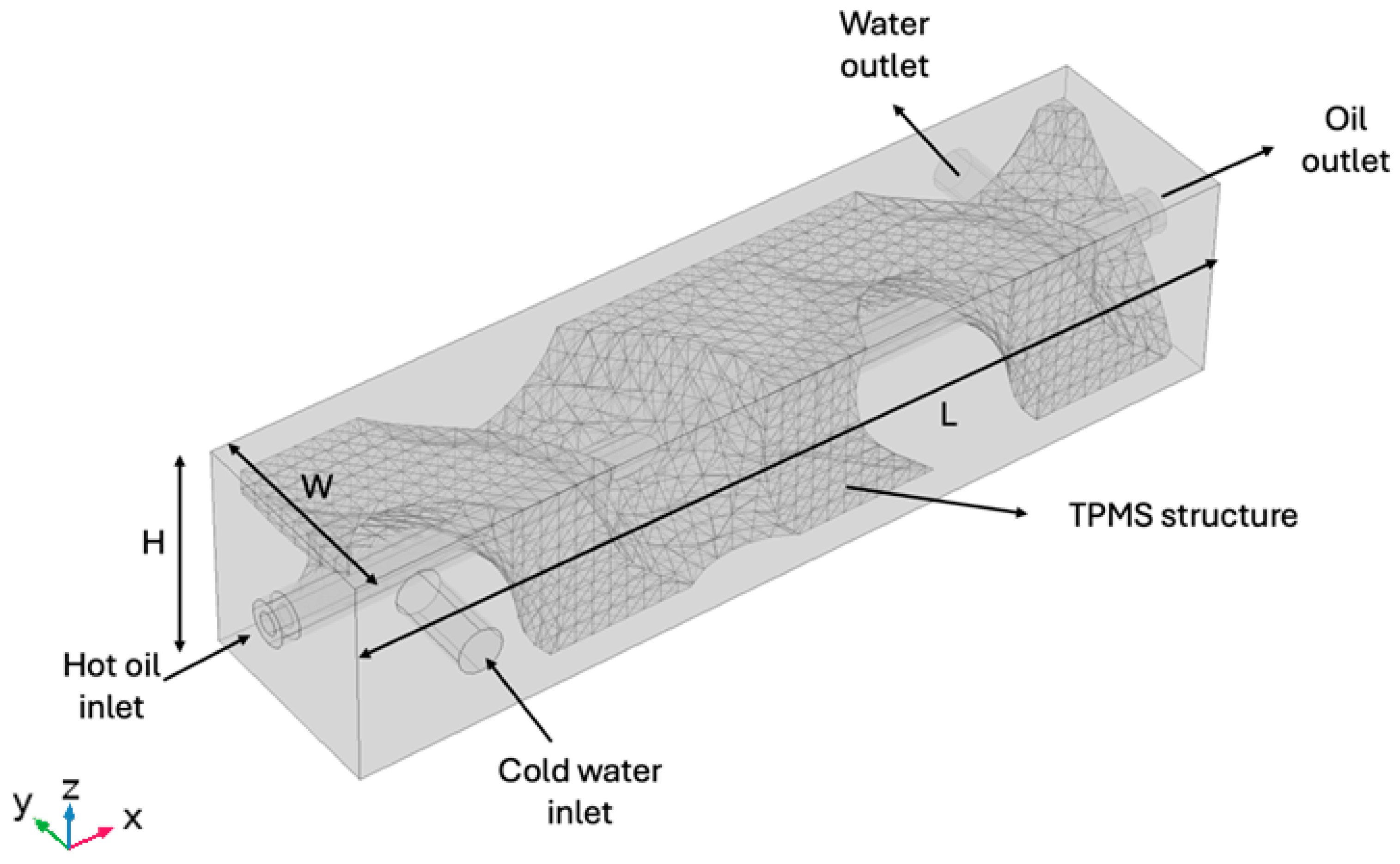
2. Problem Description

This manuscript aims to investigate the heat transfer performance and the fluid flow analysis of a heat exchanger with a triply periodic minimal surface’s porous structure. A heat exchanger (HX) is an engineering unit that transfers heat between two fluids to heat or cool a particular fluid. Different mass rates are used depending on the engineering applications. The heat exchanger is constructed from steel, copper, or aluminum. Factors affecting the design are the material cost, pressure drop, structural integrity, corrosion, wall thickness, and heat transfer coefficient. Different standard heat exchanger designs can be easily found in the paper by Kuppan [31]. The shell and tube design is the most widely used and studied form of heat exchanger. In the current model, the two fluids enter at different temperatures.
The first fluid circulates in small pipes of a tube bundle, and the second fluid fills the shell surrounding the tubes. In the present case, one fluid enters a straight pipe connected to the TPMS structure, whereas the second fluid floods the outer shell, cooling this TPMS structure. Two cases were investigated: the first was a parallel flow, and the second was a counterflow. Figure 1 shows the model under investigation. Flow configuration and internal configuration are crucial configurations that must be addressed for the flow configuration when the two fluids travel in the same direction, which is called parallel flow. In the current model, when parallel flow is applied, fluids in each inlet enter the heat exchanger near each other, thus creating a significant temperature differential around the inlet. Figure 1 presents the two inlet fluids. The two fluids enter and move in opposite directions in the second counterflow case. One may find that each of the fluid inlets is, therefore, exposed to an outlet that has undergone the total heat transfer of the heat exchanger. Thus, the temperature differential between the two streams is more consistent across the entire heat exchanger length.
As shown in Figure 1, the outer rectangular shell has a length of L equal to 5.2 cm, a width of W equal to 1.2 cm and a height H equal to 1.2 cm. The hot oil enters through a double wall pipe having an internal diameter of 0.63 mm, an outer diameter of 1.25 mm, and a length of 5.4 cm. Thus, the pipe protrudes 5 mm from each side of the outer shell. On the other hand, the water enters from a pipe with a diameter of 2.5 mm and a length of 5 mm, as shown in Figure 1. The exit pipe at the opposite side of the outer shell has dimensions identical to those of the inlet pipe.
As shown in Figure 1, the identified TPMS structure is the triply periodic minimum surface structure, mainly being a porous structure connected to the internal horizontal pipe. Saghir et al. [16] studied the TPMS structure and experimented to investigate the usefulness of this porous structure in cooling heat sinks. They demonstrated that such a structure provides a uniform heat distribution and can remove heat. The gyroid structure is used in the experimental setup, and the model is treated as a solid structure in the finite element analysis. These structure shapes have a repeating pattern in three dimensions and are local minima for surface area to volume ratio. A gap is created between the TPMS and the wall of the rectangular structure to minimize the pressure drop. Here, we are investigating heat removal performance without investigating the pressure drop. In engineering, this property of minimum area can provide a low-pressure decline while allowing the fluid to circulate in different directions toward a better cooling system. This theory of TPMS is not new to the scientific community, but what makes it evident to use right now is the availability of 3D printing of different metals. This manuscript will investigate three different TPMS structures in this context. These are the gyroid sheet structure, diamond sheet structure, and Fischer-Koch S sheet structure (FKS). In the TPMS structure, four different porosities φ equal to 40%, 50%, 60%, and 70% will be investigated. The most crucial variable to be taken into consideration is the surface area of the structure. Table 1 presents the surface area measured in our cases.
As shown in Table 1, the higher the surface area, the less porosity there is. Also, it is interesting to notice that the FKS structure exhibits a higher surface area.

3. Finite Element Formulation and Boundary Conditions

As indicated earlier, three different TPMS structures will be studied. On the modelling side, the finite element methods are used via the commercial software COMSOL version 6. The fluid in the analysis is water, which is used as a cooling fluid, and oil, which is the circulating hot fluid. Both fluids are assumed Newtonian and incompressible, and the flow is laminar.
Table 2 presents the physical properties of the fluid under consideration. For that case, the following formulations are used. The formulation used in the analysis is the Navier–Stokes equation, which is in three dimensions, and the energy equation.
Navier–Stokes formulation in the x direction
ρ f u u x + v u y + w u z = p x + μ f 2 u x 2 + 2 u y 2 + 2 u z 2
Navier–Stokes formulation in the y direction
ρ f u v x + v v y + w v z = p y + μ f 2 v x 2 + 2 v y 2 + 2 v z 2
Navier–Stokes formulation in the z direction
ρ f u w x + v w y + w w z = p z + μ f 2 w x 2 + 2 w y 2 + 2 w z 2
Energy formulation
ρ f C p u T x + v T y + w T z = k f 2 T x 2 + 2 T y 2 + 2 T z 2
As shown, the above equation is solved using COMSOL software. In this equation, u, v, and w are the three-direction velocity, p is the pressure, and the x, y, and z variables are the rectangular coordinate system. The fluid properties, whether water or oil, are identified by the thermal conductivity kf and the specific heat capacity Cp, the dynamic viscosity by  μ f ,  and the density by  ρ f .

3.1. Boundary Conditions of the System

Different boundary conditions are applied, as shown in Figure 1:
(i)
The oil enters at a temperature of Tinoil = 87 degrees Celsius and a mass rate of 1 × 10⁻⁶ kg/s which correspond to a Reynolds number equal to 0.04.
(ii)
The water enters at a temperature Tinwater = 5 degrees Celsius and three inlet mass rates of 1 × 10⁻⁵ kg/s, 1 × 10⁻⁴ kg/s, and 1 × 10⁻³ kg/s which correspond to Reynolds numbers equal to 5, 50, and 500, respectively.
(iii)
All external surfaces are assumed adiabatic,  T S u r f a c e n = 0 ,  and for the flow, no-slip boundary conditions are applied.

3.2. Non-Dimensional Parameters

To assess the performance of the heat exchanger using different TPMS structures, heat removal and the local Nusselt number in the right non-dimensional term will be studied. It is defined as
N u = h D h k f
Here, the heat convection coefficient h is calculated as the conductive heat flux q″ at the interface between the hot oil pipe and the TPMS structure, divided by the difference between the pipe surface temperature Ts and the inlet flow temperature Tin. Thus,
h = q ( T s T i n w a t e r )
On the other hand, the hydraulic diameter is four times the TPMS surface area divided by the perimeter of the inlet heat exchanger cover. The friction coefficient is defined as shown in Equation (7) as
f = 0.5 p · D h ρ f L u i n 2
The inlet velocity is defined as uin p  is the pressure difference between the water inlet and water outlet, and L is the heat exchanger length. The definition of variables can be found in the nomenclature section. Although the pressure drop is essential, one can combine the thermal effect and the hydraulic effect by calculating the performance evaluation criterion defined as
P E C = l o c a l   N u f 1 3
Finally, the rate of heat transfer is Q and expressed in Watts. The equation is
Q = U A s l m
Here,  l m  is the log mean temperature difference which is the suitable form of the average temperature difference for use in the analysis of heat exchangers and U the overall heat transfer coefficient.

3.3. Solution Technique and Convergence Criteria

The finite element method is combined with the segregated method. As mentioned in the reference [32], when the residue of all variables, such as the pressure, temperature, and the three velocities, is less than 10-6, the solution is said to converge. The steady-state problem is solved simultaneously with the fluid and heat transfer equations after applying the boundary condition. More detailed information about the convergence criteria and solution technique can be easily found in the COMSOL manual [33].

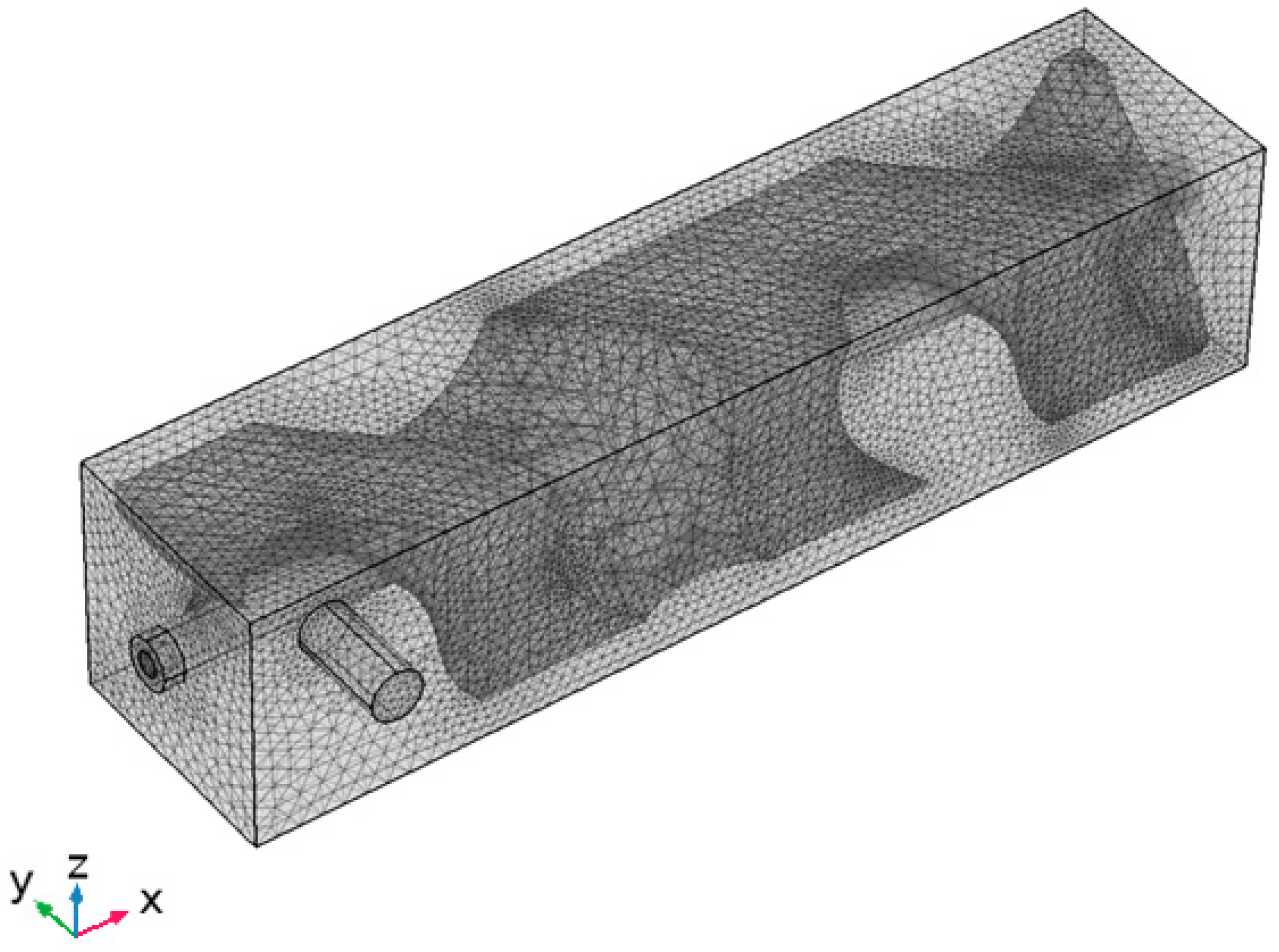
3.4. Mesh Sensitivity Analysis

Mesh analysis is detrimental to ensuring one uses the optimum mesh for all numerical analysis. For that reason, mesh sensitivity analysis is conducted, considering the average Nusselt number.
Water is used as the cooling fluid, and oil is used to cool the hot fluid. The mass rate of the water is 1 × 10⁻⁶ kg/s, and the oil mass rate is set constant at 1 × 10⁻⁶ kg/s. The inlet temperature of the oil is set at 87 degrees Celsius, whereas the water-cooling temperature at the inlet is set at five degrees Celsius. The porosity is set at 70%, and the structure is designed using sheet gyroid cells. The results revealed that the optimum mesh comprises 1,988,916 domain elements, 147,818 boundary elements, and 31,439 edge elements. This is obtained after the variation in the Nusselt number between two different meshes did not exceed 1% in value. Figure 2 presents the final mesh adopted in the current analysis.

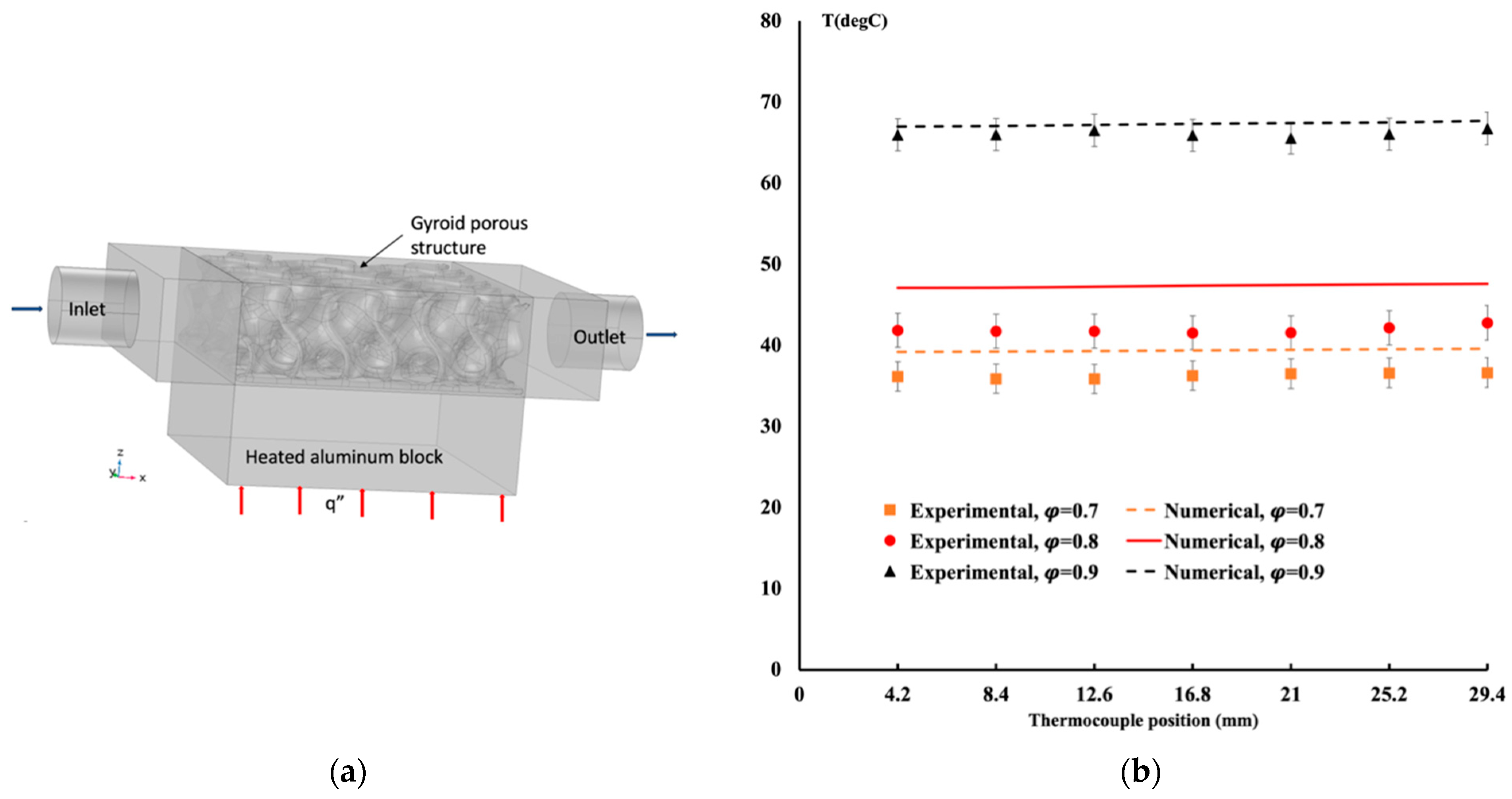
3.5. Comparison with Experimental Data

Saghir et al. [16] studied heat removal using a TPMS porous structure to demonstrate the accuracy of the mesh used in the current model. The heat sink dimension has a square base of 37.5 mm in length and 12.7 mm in height. The TPMS is made of aluminum, and the heated block is below the heat sink. The experiment is conducted for different flow rates with a constant heat flux of 30,800 W/m2. Temperature is measured 1 mm below the TPMS and the heated block interface. COMSOL software is used to compare this with the gyroid TPMS structure. As shown in Figure 3, good agreement is achieved between the two data sets. Figure 3a measures the temperature distribution 1 mm below the TPMS structure inside the aluminum block. The comparison with the numerical data is shown in Figure 3a. Depending on the flow rate, the difference between the experimental measurement and the numerical results is less than 7% for the maximum.

4. Results and Discussion

Three different TPMS structures for porosity ranging from 40% to 70% are under investigation. The first is a gyroid with a unit cell of 3 cm. The second is an FKS structure with a similar cell size, and the third is a diamond TPMS. All three cases have similar porosity but different surface area. Table 1 presents the surface areas for different porosities.
As shown in Table 1, as the porosity increases, the surface area decreases for all cases. Also, the FKS structure has the highest surface area. TPMS can act as a fin to extract heat from the pipe by circulating hot fluid.

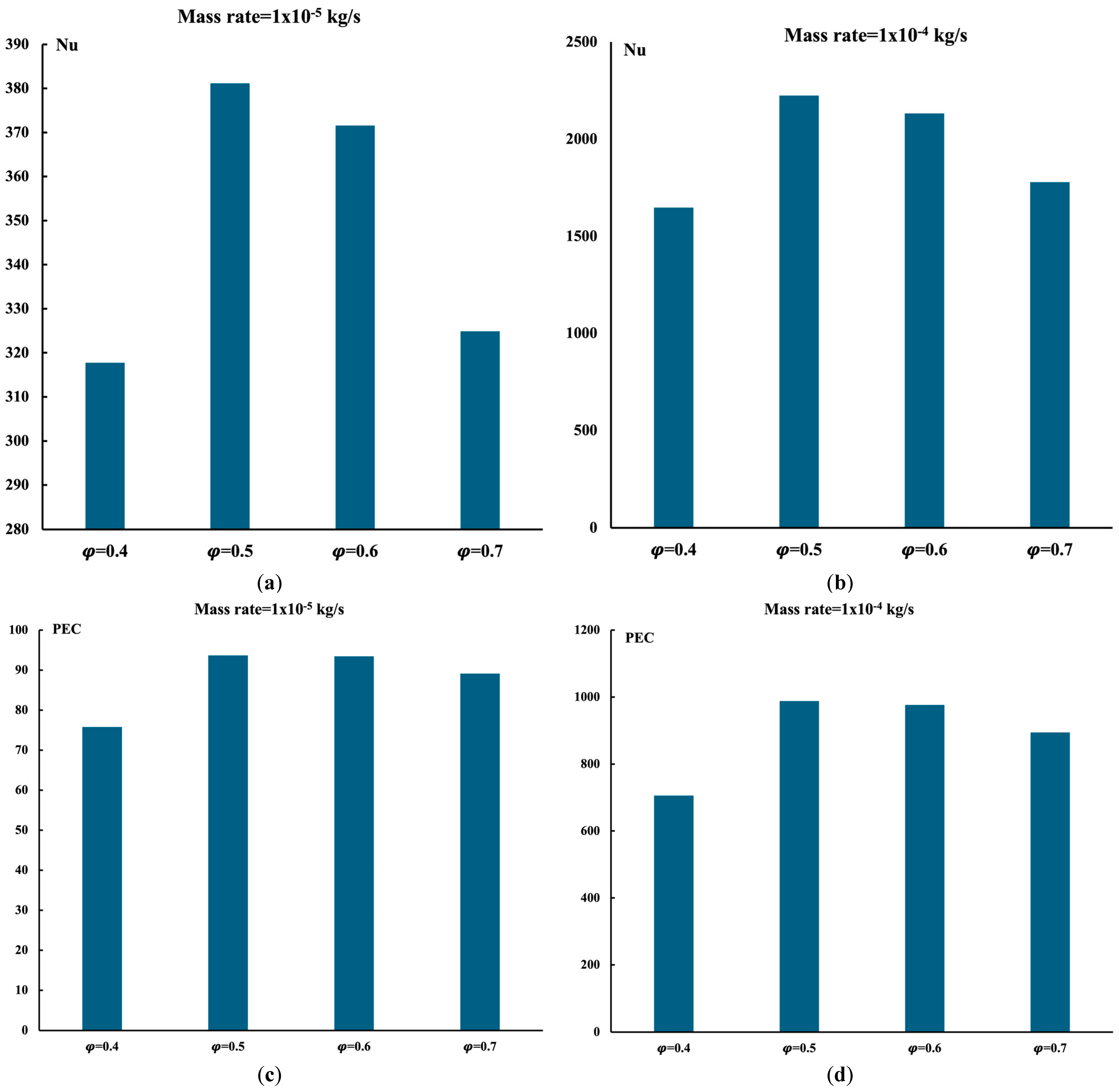
4.1. Heat Exchanger in the Presence of Gyroid TPMS

Figure 4 presents different parameters that will influence the performance of the heat exchanger when the gyroid structure is used.
In this analysis, the oil circulates at a constant mass rate of 1 × 10⁻⁶ kg/s, whereas the cooling water circulates at two different mass rates of 1 × 10⁻⁵ kg/s and 1 × 10⁻⁴ kg/s. As shown in Figure 4a, the Nusselt number varies nonlinearly with the porosity. The optimum heat extraction is at a porosity of 0.5. This observation is valid for the two different water flow rates under study. The flow appears to circulate with less resistance as the porosity increases, leading, at 0.7, to less heat extraction. More extended circulation inside the structure leads to more heat extraction. As shown in Table 1, at a porosity of 0.7, the gyroid occupies the lowest surface area. However, in the same table, the surface area is at its maximum when the porosity is 0.4, but heat extraction exhibits higher heat removal at 0.5. This is due to the complex structure of the gyroid creating more channels for cooling at the porosity of 0.5. To follow up on the type of structure, the pressure drop was calculated, and the performance evaluation criterion was determined. This parameter PEC combines thermal performance with a hydraulic or pressure drop effect.
As shown in Figure 4c,d, regardless of the mass flow rate, the gyroid with a porosity of 0.5 exhibits the best configuration for heat removal. Continuing the investigation, Figure 4e,f present the total amount of heat extracted and the overall heat transfer coefficient. It is evident from Figure 4f that, at a porosity of 0.5, the overall heat transfer is at its maximum value. Thus, this confirms that for parallel flow configuration in the presence of the gyroid, the system performs best at a porosity of 0.5.
Figure 5 presents the gyroid’s complex flow structure and the heat exchanger’s temperature distribution when the porosity equals 0.5. It is evident from 5b that the cooling is at its best, and the heat inside the oil pipe is slowly cooled down as the flow circulates in the structure. A large temperature gradient is observed.

4.2. Heat Exchanger in the Presence of Diamond and FKS Structures

In the previous model using a gyroid structure, the Nusselt number exhibits a non-linear variation as the porosity increases. Also, it was found that at a porosity of 0.5, the gyroid leads to a higher Nusselt number, and its performance evaluation criterion is the highest amongst those for the gyroid structure. The calculation is repeated for a diamond and an FKS configuration, as shown in Figure 6. The mass rate displayed in this case is identical to the previous case. As shown in Figure 6a,b, a linear increase in the Nusselt number as the porosity increases is observed. The diamond structure exhibits higher heat removal than the FKS structure.
As shown in Table 1, the higher the surface area, the lower the heat removal, thus lowering the Nusselt number. Based on Table 1, for a specific structure like FKS, for instance, when the porosity increases, the surface area decreases, which is a trivial behavior. With a decrease in surface area, the structure acts like fin sheet surfaces and delivers a higher Nusselt number. A similar observation is made for the FKS structure, which contradicts the gyroid structure case. The performance evaluation criterion is displayed in Figure 6c,d. The pressure drop in the FKS structure is more significant in magnitude, leading to a lower PEC. Similarly, as shown in Figure 6e,f, diamond structures deliver a higher overall heat transfer coefficient. Linear variation in the overall heat transfer coefficient is shown as the porosity increases for both cases, contrary to the gyroid structure, which exhibits higher magnitude and constant variation.

4.3. Comparison between Gyroid, Diamond, and FKS Structures

It is beneficial to compare the performance of the three structures, aiming to find the best case for heat removal. On the other hand, designing a heat exchanger that exhibits lighter weight is helpful, especially for marine or aerospace applications. Material types play a role in heat enhancement but at a higher cost.
Figure 7 presents the variation in the Nusselt number as the surface area of the structure varies and as the porosity differs as well. Table 1 shows that more void space is available as the porosity increases, leading to a lower surface area. Figure 7a shows that the gyroid structure provides a higher Nusselt number when compared to the other two structures under investigation. In addition, at a porosity of 0.5, as shown in Figure 7b, the gyroid is the best structure for a heat exchanger application. This observation is similar if the mass rate of the cooling water is lower in magnitude.
The friction factor is an essential parameter to investigate since a lower pressure drop is the ideal design condition. Figure 8 presents the average Nusselt number as a function of the friction coefficient. The diamond and FKS structures show a linear variation in the average Nusselt number with the friction coefficient. The non-linearity of the Nusselt number for the gyroid is observed. The gyroid structure shows the lowest friction coefficient, thus lowering the pressure drop. Therefore, in Figure 4d, the performance evaluation criterion is the highest.
Different flow circulations within the porous structure can affect the performance of the heat exchanger. Thus, any alteration that changes the flow profile passing through the structure can affect the heat transfer rate. This also will lead to different exit temperatures. We have demonstrated that the most apparent factor impacting the performance of any TPMS structure is the specific TPMS used. Gyroid demonstrated the highest Nusselt number when the porosity was equal to 0.5. In the gyroid design, one may notice different channels changing shape; the most common is the wavy channel. In addition, it was noticed that some channels are blocked at the end of the structure, forcing the fluid to re-circulate. This allows the fluid to take a longer path before exiting the heat sink. Thus, higher heat extraction is observed. Tortuosity can be identified as a non-dimensional quantity dependent on a particular structure and independent of the flow rate. According to different researchers [34,35], tortuosity is the ratio of the mean curved path distance travelled by an element in the fluid to the equivalent linear distance in the flow direction. In the current paper the tortuosity is defined as shown in Equation (10).
Tortuosity = A v e r a g e   m a g n i t u d e   o f   t h e   i n t r i n s i c   v e l o c i t y   o v e r   t h e   e n t i r e   v o l u m e t h e   v o l u m e t r i c   a v e r a g e   o f   i t s   c o m p o n e n t   a l o n g   t h e   m a c r o s c o p i c   f l o w   d i r e c t i o n
Based on the definition, the flow rate does not affect the calculation of this non-dimensional term.
Based on Figure 9, the diamond and the FKS structures show a slight variation in tortuosity with the porosity, contrary to the gyroid structure, where a linear variation is observed. The average tortuosity variation is between 1.32 for a gyroid structure with a porosity of 0.7 and 1.49 for an FKS structure with a porosity of 0.7. This is mainly due to the porous structure under investigation. Also, we can demonstrate here that tortuosity alone is an insufficient non-dimensional term to predict the performance of a heat exchanger system. Tortuosity may be dependent on the pressure drop. Thus, the higher the tortuosity, the higher the pressure drop.

5. Conclusions

Cooling engineering equipment is one of the top priorities in engineering design. Heat exchangers have been used for a long time as systems capable of cooling large equipment. Amongst the issues facing heat exchangers are corrosion and pressure drop. Different types of heat exchangers are available on the market, and the most used ones are shells and tubes. This present study aims to develop lightweight and efficient heat exchangers with applications in space and aerospace applications. A horizontal tube where hot fluid circulates is encapsulated by a porous structure created using the triply periodic minimum surface approach. The entire system is enclosed inside a rectangular box where low-temperature water circulates to remove heat from the horizontal pipe. Three porous structures were used and studied, mainly a gyroid, diamond, and FKS structure. The porous model has porosity varying from 40% to 70%. The surface area of this structure, which acts as fins, has a different surface area. The gyroid structure’s surface areas vary between 15.5 cm2 and 21.25 cm2. The diamond structure’s surface areas vary between 23.13 cm2 and 27.289 cm2. Finally, the FKS structure varies between 20.08 cm2 and 24 cm2. Two different water mass rates are applied toward cooling the system when the inlet temperature is set to five degrees Celsius. The results revealed the following:
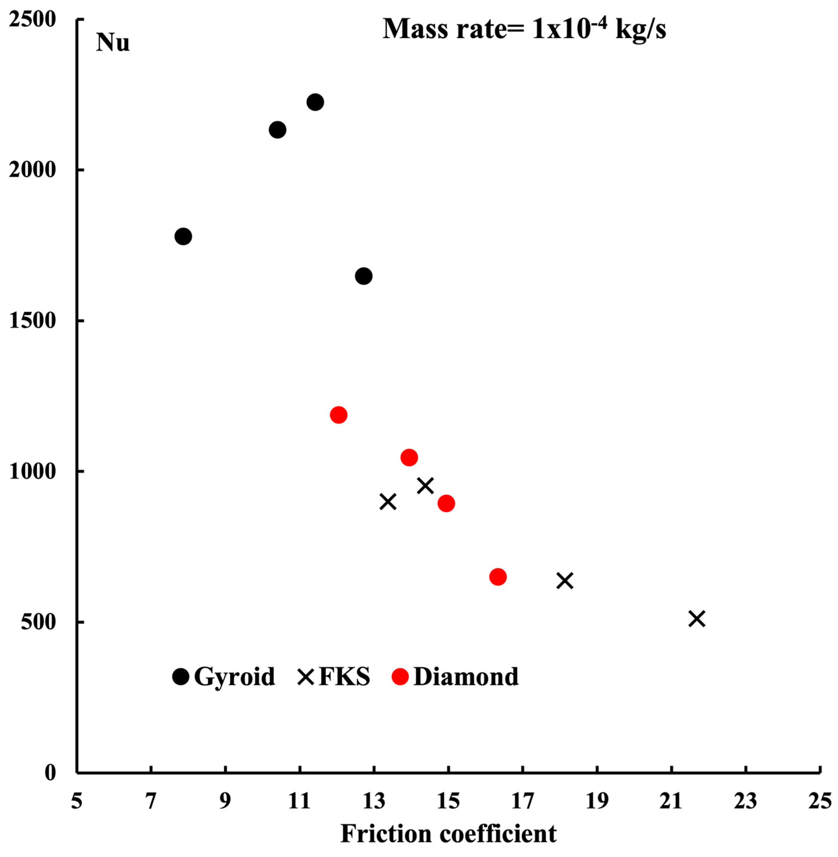
  • The gyroid exhibits the highest Nusselt number toward heat removal among the three structures under investigation. The reason for this finding is the development of wavy channels inside the structure, thus allowing the fluid to circulate longer before exiting the heat sink.
  • The highest Nusselt number is found at a porosity of 0.5 within the gyroid structures with different porosities. The maximum average Nusselt number is found to be near 2250.
  • Pressure drop varies between structures, and the gyroids exhibit the lowest pressure drops. This lower pressure drop is the formation of a wavy and straight channel.
  • A uniform overall heat transfer is observed for the gyroid case and has the highest value among the three structures.
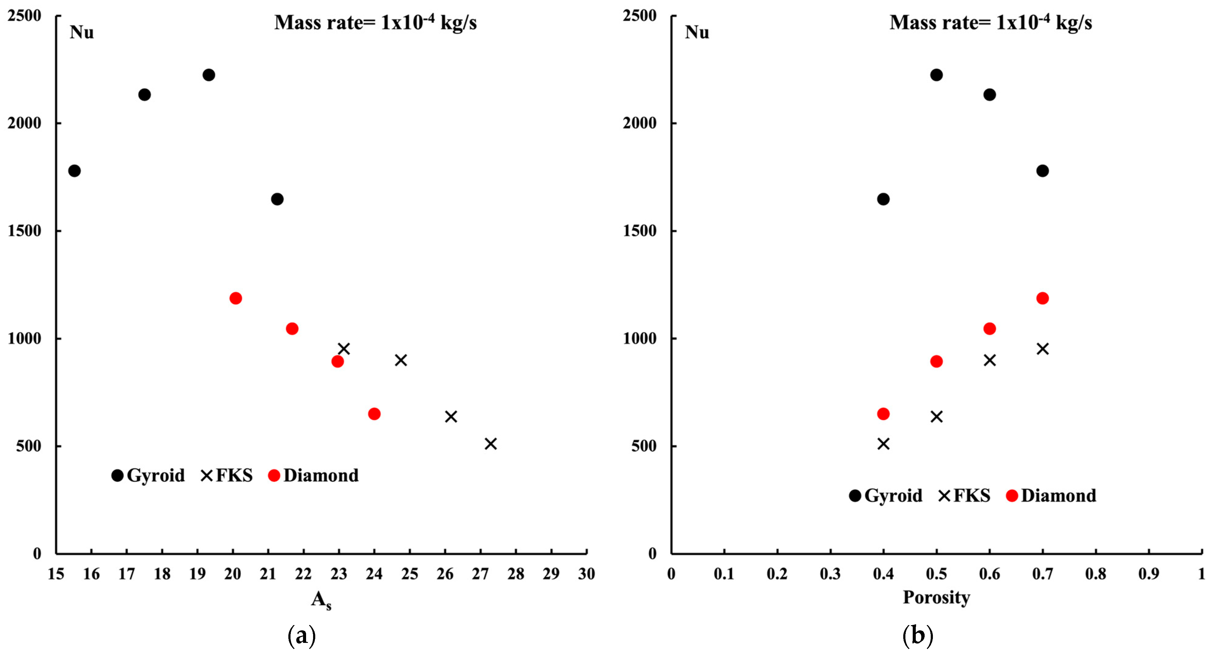
  • A linear variation in the average Nusselt number as a function of the structure surface area is detected for the FKS and diamond structures, contrary to the gyroid structures where nonlinearity is observed.
  • A similar observation about the Nusselt number versus the surface area is detected when the Nusselt number varies with porosity.
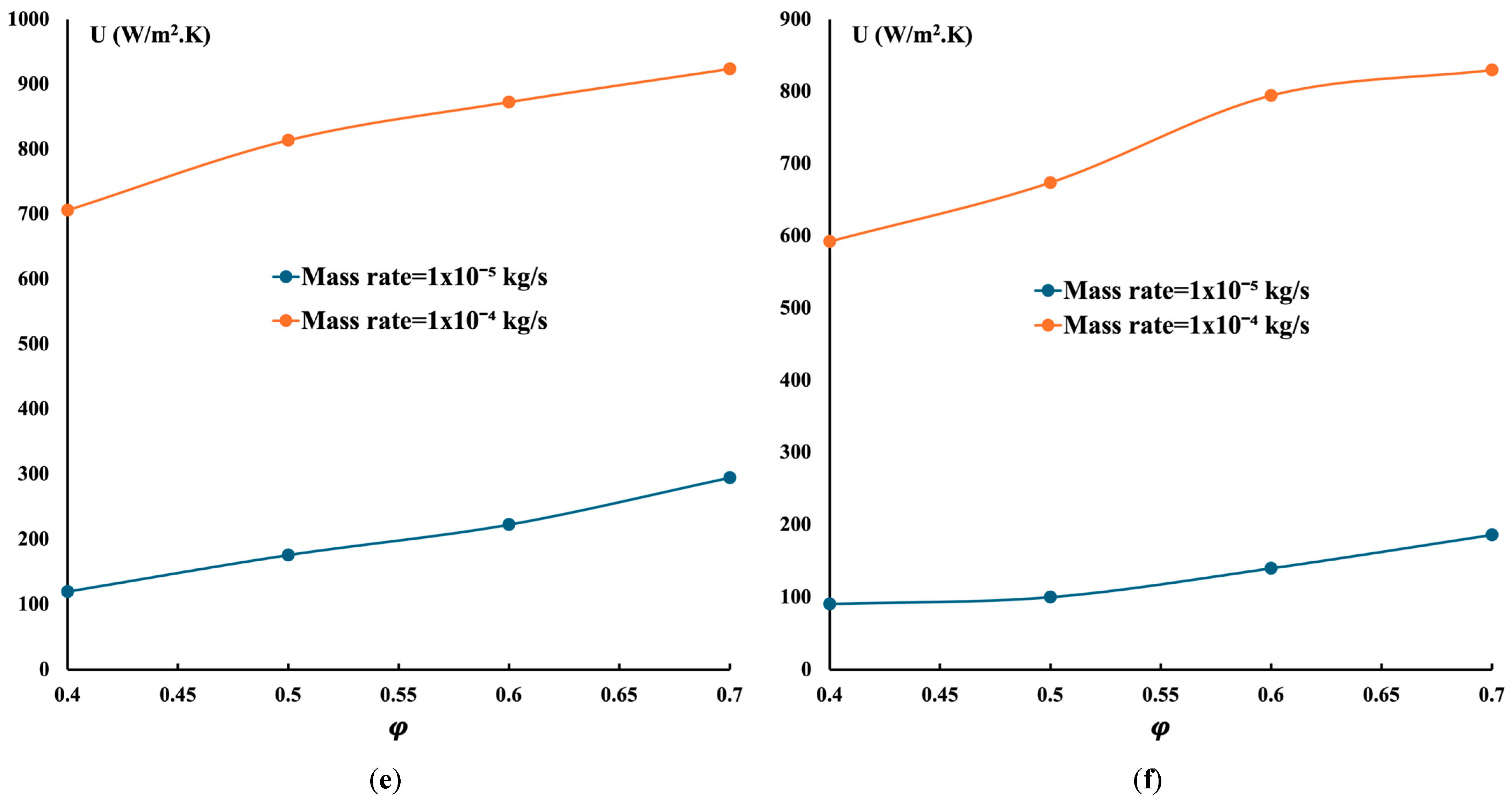
  • The overall heat transfer coefficients of the heat exchangers for the three structures have been studied. They reveal that the gyroid structure achieved the highest overall heat transfer, around 1000 W/m2·K, compared to the FKS and diamond structures. Thus, the gyroid is more suitable for heat exchangers.
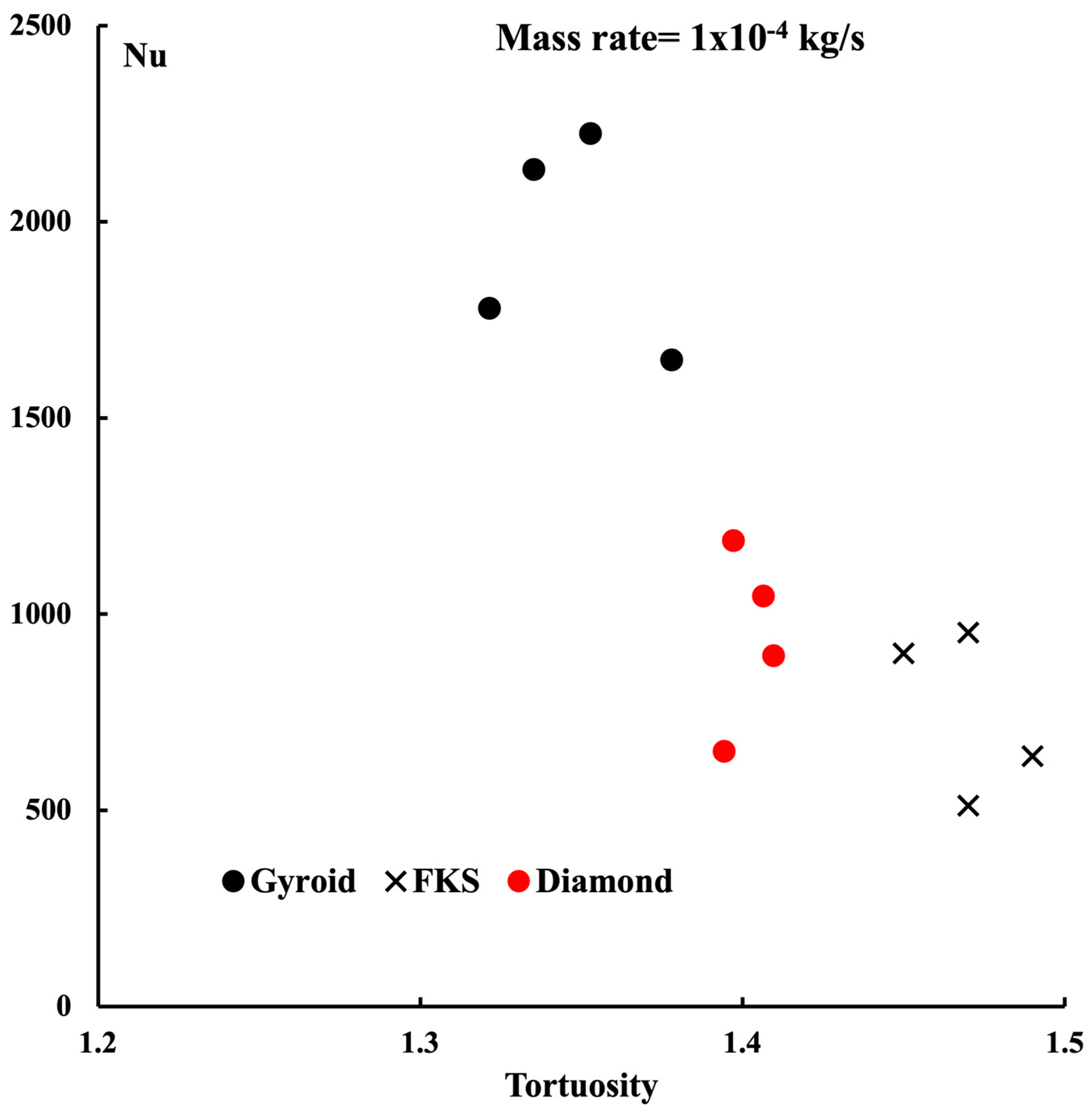
  • Tortuosity, unrelated to the flow, is constant for the diamond and FKS structures but nonlinear for the gyroid structure.
One may conclude that a heat exchanger with a gyroid structure is the best cooling system.

Author Contributions

Conceptualization, M.Z.S. and M.Y.; methodology, M.Z.S.; software, M.Z.S. and M.Y.; validation, M.Z.S. and M.Y.; formal analysis, M.Z.S.; investigation, M.Z.S. and M.Y.; resources, M.Z.S.; funding acquisition, M.Z.S. All authors have read and agreed to the published version of the manuscript.

Funding

The authors acknowledge the financial support of NSERC grant number RGPIN-2020-07021.

Data Availability Statement

The original contributions presented in the study are included in the article.

Conflicts of Interest

The authors declare no conflict of interest.

Nomenclature

Variables Greek Letter
pFluid pressure in Pa ρ f Fluid density in kg/m3
u,v,wFluid velocity in m/s μ f Fluid dynamic viscosity in kg/m.s
x,y,zCoordinate system in m κ Permeability in m2
q″Heat flux in W/m2 φ Porosity [17]
TTemperature in degrees CSubscript
kThermal conductivity in W/m.KinInlet
CpSpecific heat capacity in J/kg.KoutOutlet
AsTPMS surface areafFluid
Non-dimensional sSolid
ReReynolds numberTPMSTriply periodic minimum surfaces
NuNusselt number
fFriction coefficientPECPerformance evaluation criterion

References

  1. Sekulic, D.P.; Shah, R.K. Fundamentals of Heat Exchanger Design; John Wiley & Sons: Hoboken, NJ, USA, 2003. [Google Scholar]
  2. ScheithauerKordaß, R.; Noack, K.; Eichenauer, M.F.; Hartmann, M.; Abel, J.; Ganzer, G.; Lordick, D. Potentials and chal-lenges of additive manufacturing technologies for heat exchanger. In Advances in Heat Exchangers; IntechOpen: London, UK, 2018; Volume 4. [Google Scholar]
  3. Arie, M.A.; Shooshtari, A.H.; Tiwari, R.; Dessiatoun, S.V.; Ohadi, M.M.; Pearce, J.M. Experimental characterization of heat transfer in an additively manufactured polymer heat exchanger. Appl. Therm. Eng. 2017, 113, 575–584. [Google Scholar] [CrossRef]
  4. Kaur, I.; Singh, P. State-of-the-art in heat exchanger additive manufacturing. Int. J. Heat Mass Transf. 2021, 178, 121600. [Google Scholar] [CrossRef]
  5. Kelkar, K.M.; Patankar, S.V. Numerical prediction of flow and heat transfer in a parallel plate channel with staggered fins. J. Heat Transf. 1987, 109, 25–30. [Google Scholar] [CrossRef]
  6. Lopez, J.; Anand, N.K.; Fletcher, L.S. Heat transfer in a three-dimensional channel with baffles. Numer. Heat Transf. Part A Appl. 1996, 30, 189–205. [Google Scholar] [CrossRef]
  7. Sahin, B.; Demir, A. Performance analysis of a heat exchanger having perforated square fins. Appl. Therm. Eng. 2008, 28, 621–632. [Google Scholar] [CrossRef]
  8. Unger, S.; Beyer, M.; Gruber, S.; Willner, R.; Hampel, U. Experimental study on the air-side thermal-flow performance of additively manufactured heat exchangers with novel fin designs. Int. J. Therm. Sci. 2019, 146, 106074. [Google Scholar] [CrossRef]
  9. Yeranee, K.; Rao, Y. A review of recent investigations on flow and heat transfer enhancement in cooling channels em-bedded with triply periodic minimal surfaces (TPMS). Energies 2022, 15, 8994. [Google Scholar] [CrossRef]
  10. Al-Ketan, O.; Ali, M.; Khalil, M.; Rowshan, R.; Khan, K.A.; Abu Al-Rub, R.K. Forced convection computational fluid dynamics analysis of architected and three-dimensional printable heat sinks based on triply periodic minimal surfaces. J. Therm. Sci. Eng. Appl. 2021, 13, 021010. [Google Scholar] [CrossRef]
  11. Jung, Y.; Torquato, S. Fluid permeabilities of triply periodic minimal surfaces. Phys. Rev. E 2005, 72, 056319. [Google Scholar] [CrossRef]
  12. Dong, Z.; Zhao, X. Application of TPMS structure in bone regeneration. Eng. Regen. 2021, 2, 154–162. [Google Scholar] [CrossRef]
  13. Li, W.; Li, W.; Yu, Z. Heat transfer enhancement of water-cooled triply periodic minimal surface heat exchangers. Appl. Therm. Eng. 2022, 217, 119198. [Google Scholar] [CrossRef]
  14. Wang, J.; Chen, K.; Zeng, M.; Ma, T.; Wang, Q.; Cheng, Z. Assessment of flow and heat transfer of triply periodic minimal surface based heat exchangers. Energy 2023, 282, 128806. [Google Scholar] [CrossRef]
  15. Al-Ketan, O.; Abu Al-Rub, R.K. MSLattice: A free software for generating uniform and graded lattices based on triply periodic minimal surfaces. Mater. Des. Process Commun. 2021, 3, 205. [Google Scholar] [CrossRef]
  16. Saghir, M.Z.; So, J.; Rasheed, H.; Ilesaliev, D. Forced Convection in Porous Medium Using Triply Periodical Minimum Surfaces. Fluids 2023, 8, 311. [Google Scholar] [CrossRef]
  17. Saghir, M.Z.; Kerme, E.D.; Hajialibabei, M.; Rasheed, H.; Welsford, C.; Al-Ketan, O. Study of the Thermal and Hydraulic Performance of Porous Block versus Gyroid Structure: Experimental and Numerical Approaches. Energies 2024, 17, 861. [Google Scholar] [CrossRef]
  18. Yan, G.; Sun, M.; Zhang, Z.; Liang, Y.; Jiang, N.; Pang, X.; Song, Y.; Liu, Y.; Zhao, J. Experimental study on flow and heat transfer performance of triply periodic minimal surface structures and their hybrid form as disturbance structure. Int. Commun. Heat Mass Transf. 2023, 147, 106942. [Google Scholar] [CrossRef]
  19. Iyer, J.; Moore, T.; Nguyen, D.; Roy, P.; Stolaroff, J. Heat transfer and pressure drop characteristics of heat exchangers based on triply periodic minimal and periodic nodal surfaces. Appl. Therm. Eng. 2022, 209, 118192. [Google Scholar] [CrossRef]
  20. Tang, W.; Zhou, H.; Zhang, L.; Zeng, Y.; Sun, L.; Zhao, Y.; Yan, M.; Jiang, C.; Yang, P.; Li, Q.; et al. A New Method to Adjust the Lattice Structure of Gyroid-Type Triply Periodic Minimal Surfaces (TPMS) and Its Effect on Convective Heat Transfer Process. Available at SSRN, p. 4263557. Available online: https://papers.ssrn.com/sol3/papers.cfm?abstract_id=4263557 (accessed on 24 June 2024).
  21. Attarzadeh, R.; Rovira, M.; Duwig, C. Design analysis of the “Schwartz D” based heat exchanger: A numerical study. Int. J. Heat Mass Transf. 2021, 177, 121415. [Google Scholar] [CrossRef]
  22. Yan, K.; Wang, J.; Li, L.; Deng, H. Numerical investigation into thermo-hydraulic characteristics and mixing performance of triply periodic minimal surface-structured heat exchangers. Appl. Therm. Eng. 2023, 230, 120748. [Google Scholar] [CrossRef]
  23. Wang, J.; Chen, K.; Zeng, M.; Ma, T.; Wang, Q.; Cheng, Z. Investigation on flow and heat transfer in various channels based on triply periodic minimal surfaces (TPMS). Energy Convers. Manag. 2023, 283, 116955. [Google Scholar] [CrossRef]
  24. Cheng, Z.; Xu, R.; Jiang, P.-X. Morphology, flow and heat transfer in triply periodic minimal surface based porous structures. Int. J. Heat Mass Transf. 2012, 170, 120902. [Google Scholar] [CrossRef]
  25. Kaur, I.; Singh, P. Flow and thermal transport characteristics of Triply-Periodic Minimal Surface (TPMS)-based gyroid and Schwarz-P cellular materials. Numer. Heat Transf. Part A Appl. 2021, 79, 553–569. [Google Scholar] [CrossRef]
  26. Careri, F.; Khan, R.H.; Todd, C.; Attallah, M.M. Additive manufacturing of heat exchangers in aerospace applications: A review. Appl. Therm. Eng. 2023, 235, 121387. [Google Scholar] [CrossRef]
  27. Thompson, S.M.; Aspin, Z.S.; Shamsaei, N.; Elwany, A.; Bian, L. Additive manufacturing of heat exchangers: A case study on a multi-layered Ti–6Al–4V oscillating heat pipe. Addit. Manuf. 2015, 8, 163–174. [Google Scholar] [CrossRef]
  28. Niknam, S.A.; Mortazavi, M.; Li, D. Additively manufactured heat exchangers: A review on opportunities and challenges. Int. J. Adv. Manuf. Technol. 2021, 112, 601–618. [Google Scholar] [CrossRef]
  29. Wei, H.; Bao, H.; Ruan, X. Machine learning prediction of thermal transport in porous media with physics-based de-scriptors. Int. J. Heat Mass Transf. 2020, 160, 120176. [Google Scholar] [CrossRef]
  30. Wei, H.; Zhao, S.; Rong, Q.; Bao, H. Predicting the effective thermal conductivities of composite materials and porous media by machine learning methods. Int. J. Heat Mass Transf. 2018, 127, 908–916. [Google Scholar] [CrossRef]
  31. Thulukkanam, K. Heat Exchanger Design Handbook; CRC Press: Boca Raton, FL, USA, 2000. [Google Scholar]
  32. da Silva, M.T.Q.S.; Cardoso, M.D.R.; Veronese, C.M.P.; Mazer, W. Tortuosity: A brief review. Mater. Today Proc. 2022, 58, 1344–1349. [Google Scholar] [CrossRef]
  33. COMSOL Manual; COMSOL Inc.: Burlington, MA, USA, 2022.
  34. Ghanbarian, B.; Hunt, A.G.; Ewing, R.P.; Sahimi, M. Tortuosity in porous media: A critical review. Soil Sci. Soc. Am. J. 2013, 77, 1461–1477. [Google Scholar] [CrossRef]
  35. Matyka, M.; Koza, Z. How to calculate tortuosity easily? In Proceedings of the Porous Media and Its Applications in Science, Engineering, and Industry: Fourth International Conference, Potsdam, Germany, 17–22 June 2012; American Institute of Physics: College Park, MS, USA, 2012; Volume 1453, pp. 17–22. [Google Scholar]
Figure 1. Model under study.
Energies 17 04275 g001
Figure 2. Finite element model.
Energies 17 04275 g002
Figure 3. Comparison between experimental measurements and numerical analysis [17]. (a) Experimental model, (b) temperature variation (Flow rate = 3.74 cm3/s).
Energies 17 04275 g003
Figure 4. Performance of the heat exchanger using gyroid structure. (a) Average Nusselt number for different porosities ( m ˙  = 1 × 10⁻⁵ kg/s). (b) Average Nusselt number for different porosities ( m ˙  = 1 × 10⁻⁴ kg/s). (c) Average PEC for different porosities ( m ˙  = 1 × 10⁻⁵ kg/s). (d) Average PEC for different porosities ( m ˙  = 1 × 10⁻⁴ kg/s). (e) Heat removed at different porosities (f). Overall heat transfer coefficient for different porosities.
Energies 17 04275 g004aEnergies 17 04275 g004b
Figure 5. Flow characteristics and temperature variation in the heat exchanger with gyroid structure ( φ  = 0.5). (a) Flow streamline. (b) Temperature variation.
Energies 17 04275 g005
Figure 6. Heat exchanger performance for diamond and FKS structures. (a) Average Nusselt for diamond structure ( m ˙  = 1 × 10⁻⁴ kg/s). (b) Average Nusselt for FKS structure ( m ˙  = 1 × 10⁻⁴ kg/s). (c) Average PEC for diamond structure ( m ˙  = 1 × 10⁻⁴ kg/s). (d) Average PEC for FKS structure ( m ˙  = 1 × 10⁻⁴ kg/s). (e) Overall heat transfer coefficient for diamond structure. (f) Overall heat transfer coefficient for FKS structure.
Energies 17 04275 g006aEnergies 17 04275 g006b
Figure 7. Variation in the Nusselt number with the structure surface area and porosity.
Energies 17 04275 g007
Figure 8. Variation in the Nusselt number with the friction factor.
Energies 17 04275 g008
Figure 9. Variation in the average Nusselt number with tortuosity.
Energies 17 04275 g009
Table 1. TPMS structure type and surface area.
GyroidSurface Area (cm2)
Porosity φ = 70%15.524
Porosity φ = 60%17.5073
Porosity φ = 50%19.3235
Porosity φ = 40%21.2585
FKS
Porosity φ = 70%23.1358
Porosity φ = 60%24.748
Porosity φ = 50%26.167
Porosity φ = 40%27.289
Diamond
Porosity φ = 70%20.087
Porosity φ = 60%21.679
Porosity φ = 50%22.965
Porosity φ = 40%24
Table 2. Physical properties of the fluid.
Fluid ρ f
(kg/m3)
μ f
(kg/m·s)
Cp
(J/kg·K)
k f
(W/m2·K)
Water998.20.00100141280.6
Engine Oil8480.02521600.137
Disclaimer/Publisher’s Note: The statements, opinions and data contained in all publications are solely those of the individual author(s) and contributor(s) and not of MDPI and/or the editor(s). MDPI and/or the editor(s) disclaim responsibility for any injury to people or property resulting from any ideas, methods, instructions or products referred to in the content.

