1. Introduction
The dynamic stability of power systems has long been recognized as an important factor for the safe operation of these systems; therefore, many solutions have been found over time to preserve it. However, the increasing integration of devices based on power electronics into power systems has caused major changes in their dynamic behavior, which is becoming increasingly dependent on the fast response of said devices [
1]. For this reason, new solutions are needed that will contribute to preserving the dynamic stability of such systems, with an emphasis on transient stability, which mostly depends on the fast response of system elements. Transient stability, also called large-disturbance rotor angle stability, deals with the ability of a power system to maintain synchronism when subjected to a large disturbance, such as a short circuit on a transmission line. The time frame of interest for transient stability studies is typically from 3 to 5 s after the disturbance [
2].
Flexible AC transmission system (FACTS) devices are considered to be effective solutions for reactive power control and transient stability [
3]. Although their application is mostly based on solving steady-state stability issues such as voltage and power flow control, or increasing transmission capacities, FACTSs can significantly dampen electromechanical oscillations and improve a power system’s dynamic response during large disturbances [
4,
5,
6]. FACTS devices are based on power electronics, which enables them to react quickly to system changes, thus participating in maintaining transient stability. Different types of FACTSs have different contributions to transient stability improvement [
7], and can generally be divided into serial, shunt, and combined devices.
The primary role of FACTS shunt devices is voltage control by injecting or absorbing the reactive power at the connection bus. Reactive power compensation increases the flow of synchronizing power between synchronous generators in the system, thus raising the power system’s transient stability limit. By adding auxiliary control circuits, power oscillations that occur during large disturbances can be dampened more effectively, further improving the transient stability of the system. The SVC oscillation damping controller is often tuned using different optimization algorithms, some of which are described in [
8,
9,
10,
11,
12].
Various SVC control strategies for transient stability improvement are described in [
13,
14,
15,
16]. In [
13], a PI controller is added to the control loop of the SVC to improve oscillation damping and voltage control. The input signal is the rotor speed deviation
. In [
14], an increase in transient stability is obtained by enhancing the steady-state power-transfer limit provided by the SVC voltage controller. In [
15], the author proposes a control strategy for FACTS shunt devices to improve the first swing stability limit by maximizing the decelerating area. This is achieved using a locally available voltage control signal. In [
16], the authors consider different locally available control signals to enhance the SVC interarea oscillation damping using observability indices.
For a long time, most research focused on SVC control strategies was based on local measurements and decentralized control. Due to changes in power systems’ dynamic behavior and the development of measurement technologies in the last few years, control strategies based on wide area monitoring systems (WAMSs) have become an increasingly active area of research in the field of power system stability [
17,
18]. An essential part of WAMSs are phasor measurement units (PMUs), which collect synchronized and precise voltage or current measurements that enable real-time system monitoring. Measurements collected by PMUs can be used to develop new control strategies that extend the operation areas of devices such as SVCs to dampen large-disturbance power oscillations and improve the transient stability of power systems [
19].
Various SVC control strategies for transient stability improvement using WAMSs are described in [
20,
21,
22,
23]. Ref. [
20] proposes a control strategy that minimizes the current magnitude along the SVC-compensated transmission line and dampens inter-area power oscillations using the voltage measurement and voltage oscillation frequencies. In [
21], SVC controllers use the estimated area angles and angular velocities to improve the system’s first swing stability and oscillation damping following a large disturbance. The control algorithm is based on the maximum reduction in the total kinetic energy of the system. Ref. [
22] presents the design of a nonlinear external damping controller using the speed deviations of generators estimated through wide-area measurements. In [
23], the authors chose the speed deviations and angular differences of generators as input signals for the SVC supplementary controller based on the residue ratio method to dampen inter-area oscillations.
In this paper, an SVC control strategy using a WAMS to improve the transient stability of a power system is presented. The proposed strategy is based on collecting voltage phasor measurements which serve as SVC controller inputs to dampen generator power and rotor angle oscillations. This is achieved by minimizing the generator’s electrical and mechanical power differences that occur during large disturbances using the particle swarm optimization (PSO) algorithm to calculate the SVC optimal reactive power injection. The novelty of the proposed strategy lies in the sensitivity coefficients used to express the generators’ active power dependence on the SVC reactive power in disturbance conditions. Thus, the SVC directly affects the damping of target generator oscillations, unlike the traditional approach, where the SVC dampens local oscillations. Although it is designed and tested for SVCs, the same strategy could be applied to static synchronous compensators (STATCOMs). The proposed strategy can be used to simultaneously dampen multiple generator oscillations, and it is tested on the IEEE 14-bus system. It is also efficient in terms of computation time and system requirements, which makes it suitable for real-time control.
The paper is divided into nine sections, the first of which is the introduction. The power system simulation model is described in
Section 2.
Section 3 compares the transient stabilities of a system with installed renewable energy sources (RESs) and a conventional system with synchronous generators. In
Section 4, the SVC working scheme is described, and in
Section 5, the control strategy for the SVC to improve the transient stability of the system is proposed.
Section 6 and
Section 7 describe the simulation procedure and the obtained results. The discussion with a conclusion is given in
Section 8.
3. RESs’ Impact on Transient Stability
Transient stability analysis is a basic dynamic calculation, based on which a system’s behavior under large disturbances can be determined. The term generator stability refers to its ability to maintain synchronism with other generators in the system during large disturbances. In the case of an unstable response, the generator rotor angle continuously increases until the synchronism is lost, which usually happens in the generator’s first swing. This loss of synchronism is associated with the critical clearing time (CCT), defined as the longest fault duration for which the synchronous operation is still maintained. The higher the CCT, the more stable the system.
Due to the increasing integration of renewable energy sources (RESs) into power systems, their impact on the transient stability of these systems should be analyzed. The analysis is carried out for two scenarios using the simulation model from
Figure 1 with the SVC switched off. In the first scenario (Scenario I), the entire production consists of synchronous generators and amounts to 270 MW. In the second scenario (Scenario II), the synchronous generators G4 and G5 connected to the 110 kV voltage level are replaced with wind turbines of the same production connected to the grid via a full-size converter. In this case, the production of these wind turbines amounts to slightly more than 20% of the total system’s production. For the mentioned two scenarios, a three-phase short circuit on the 220 kV transmission line 2-3 with different durations is simulated to determine the CCT of the generator G3, which is most affected by the fault. Due to the test network’s high inertia, the short circuit’s duration must be quite long for the generator to lose its stability. As a criterion for maintaining this stability, the first swing stability criterion is used; therefore, the duration of the simulations is 3 s.
Figure 2 shows the generator G3’s rotor oscillations for the two scenarios. For the same fault duration, the generator remains stable in Scenario I, while in Scenario II, it falls out of synchronism and loses its stability. Further simulations determine that the CCT of the generator G3 in Scenario I is 590 ms, while in Scenario II, it is 500 ms, which is 90 ms less. This makes Scenario I, with only synchronous generators, more stable compared to the system with RESs installed. The impact of RESs on transient stability can be improved by adding a control system to the converter to provide active and reactive power support to the system during faults, or by installing other devices such as SVCs. With the SVC switched on in the simulation model, the CCT of the generator G3 is extended by 40 ms in both scenarios.
5. Proposed Control Strategy
The proposed SVC control strategy is shown in
Figure 4. The first step of the proposed strategy consists of collecting synchronized voltage phasor measurements on the synchronous generator buses and their adjacent buses. The collected measurements then serve as inputs for the optimization algorithm, which determines the amount of SVC reactive power required to dampen the active power and rotor angle oscillations of the synchronous generators. The new reference voltage is calculated from the reactive power and adjusted on the SVC by a simple previously tuned PI controller. Particle swarm optimization (PSO) was chosen as the optimization algorithm due to its reliability and precision in obtaining results. It also has a short calculation time. If there are no active power oscillations in the system, the SVC reference point remains as initially set. The same applies after the transient condition passes, and if the mechanical power of the generator remains unchanged, the SVC returns to the initial setting.
Before applying the proposed strategy, it is necessary to determine the line admittances that enter the calculation of the synchronous generators’ active power oscillations, as well as the sensitivity coefficients of the voltages that enter the same calculation to the amount of injected reactive power of the SVC.
5.1. Particle Swarm Optimization
PSO is a stochastic algorithm based on a population of solutions, inspired by the behavior of flocks of birds and schools of fish. A swarm consists of a series of particles that search for a possible solution within a defined space. In each iteration, the velocity and position of these particles are adjusted to find the optimal solution of the given objective function [
26]. The swarm behavior in PSO is described by two equations, which make this algorithm simple and accessible for use. The velocity vector
and the position vector
of the particles in every iteration are calculated using the following expressions [
27]:
where
,
and
are constants,
and
random numbers between 0 and 1, and
and
are the best local and global particle positions in the previous iteration.
Another important feature of the PSO algorithm is that it is largely unaffected by the size and non-linearity of a problem and can converge to the optimal solution in most cases. For this reason, it is applied to various optimization problems in power systems [
26].
In this paper, PSO is used to determine the optimal amount of the SVC reactive power required for damping the oscillations of the synchronous generators’ active power at certain moments. The optimization algorithm calculates the minimum of the following objective function:
where
is the active power of the synchronous generator
i in the system and
is its mechanical power. In the event of a disturbance, an imbalance between these two powers will occur on swinging generators. According to the swing Equation (4), which describes the dynamic behavior of a synchronous generator during a disturbance by reducing power oscillations, the swinging generators’ rotor angle oscillations will also be reduced. The swing equation is given by the following expression [
28]:
where
is an inertia constant,
is the synchronous speed,
is the rotor angle, and
and
are the active and mechanical power of the synchronous generator
i. The active power of an individual generator is calculated according to the expression [
28]:
where
is the voltage of the generator bus,
is the voltage of its adjacent buses,
is the admittance matrix of the observed system, and
,
and
are the voltage and admittance angles. For calculating Equation (5), only the admittances of the synchronous generator buses and the admittances of the lines by which they are connected to adjacent buses are needed. All equations are expressed in the per-unit system.
5.2. Sensitivity Analysis
A sensitivity analysis is performed to determine the influence of the SVC reactive power injection on the bus voltages that enter the PSO algorithm. To determine the optimal amount of SVC reactive power injection for damping the synchronous generators’ active power oscillations, it is necessary to consider the sensitivity coefficients of the voltage amplitude
and angle
in Equation (5), according to the expressions:
where
and
are measured values of the voltage amplitude and angle at a certain moment,
is the change in the SVC reactive power injection, and
and
are the sensitivity coefficients of the voltage amplitude and angle to
. Thus, Equation (5) becomes:
When Equation (8) is combined with the objective function in Equation (3), the PSO algorithm can calculate the optimal for damping the synchronous generators’ power and rotor angle oscillations at any given moment, which is then used to adjust the SVC setting.
The conditions during a fault are different from those in a steady state, therefore, the sensitivity coefficients during the transient condition are different from those during normal system operation. During a disturbance, such as a short circuit, a voltage drop occurs on nearby buses, and generators must meet the high reactive power demand. For this reason, it is not possible to calculate the sensitivity coefficients for generator buses using classical methods based on power flows. In this paper, the coefficients are determined through a certain number of simulations and are calculated for different power injections, according to the expressions:
6. Simulation Procedure
Simulations are carried out in the DIgSILENT PowerFactory 2022 software package to test the proposed SVC control strategy during transient conditions. A loss of transient stability mainly occurs due to a continuous increase in the rotor angle due to insufficient synchronizing torque. In this case, the generator often falls out of synchronism in the first swing of the rotor angle. This loss of synchronism can also occur after a stable first swing due to insufficient damping of the rotor angle oscillations [
28]. The proposed control strategy reduces the amplitude and slope of the rotor angle oscillation curve of the synchronous generators in the system. This reduced angle curve slope means reduced speed deviations of the generators. The time frame of interest in transient stability analysis ranges between 3 and 5 s from the onset of the disturbance.
As already stated in the introduction, an SVC without auxiliary controls does not contribute to oscillation damping. For this reason, the performance of the SVC without a damping function was compared with that of the SVC with the proposed control strategy. The simulation procedure will be explained on the generator G3 from the simulation model shown in
Figure 1. The three-phase short circuit in this scenario is on the 220 kV transmission line 2–3 and lasts 100 ms. The start of the short circuit is at 0.1 s and the line is disconnected at 0.2 s.
Before the simulation, it is necessary to carry out a sensitivity analysis for the observed short circuit. The sensitivity coefficients are calculated for the voltage amplitude and angle according to Equation (9) and Equation (10) during the transient condition in 80 ms intervals, with
ranging from −120 Mvar to 125 Mvar. Their average value is then used in Equation (8).
Figure 5 and
Figure 6 show some of the calculated voltage amplitude and angle sensitivity coefficients during the transient condition for 220 kV buses 1–5 of the simulation model. Coefficient values are shown for the first 500 ms of the calculation. In all simulations, the observed generators are those connected to the 220 kV voltage level, to which the SVC is also connected, due to their much higher sensitivity to the SVC reactive power injection compared to the generators connected to the 110 kV voltage level. This was concluded from the performed voltage sensitivity analysis.
The first step of the simulation procedure is to collect the voltage amplitude and angle values required for the calculation of
according to Equation (5). In a real power system, this step would be conducted by collecting synchronized voltage phasor measurements from PMUs. The collected data enter the PSO algorithm written in the Python programming language, which determines the amount of
needed to obtain the minimum of the objective function in Equation (3). The swarm consists of 20 particles, the usual number for problems of small dimensions [
29], and the global optimum is determined after 100 iterations. The PSO algorithm calculation time is around 10 ms. From the
determined by the optimization, a new reference voltage setting
is calculated and adjusted on the SVC according to the expression:
where
is the voltage amplitude of the SVC connection bus measured at certain moments and
is its voltage amplitude sensitivity coefficient to
. The process is repeated every 80 ms to collect the necessary data, execute the optimization algorithm, and send the setting command to the SVC. The specified interval can be shorter, depending on the speed of the used technology.
Table 1 shows the obtained
values that are adjusted on the SVC at the indicated times. During a short circuit due to a voltage drop on the SVC, it is determined that it is optimal to keep
at the initial setting, the same as before the short circuit occurrence.
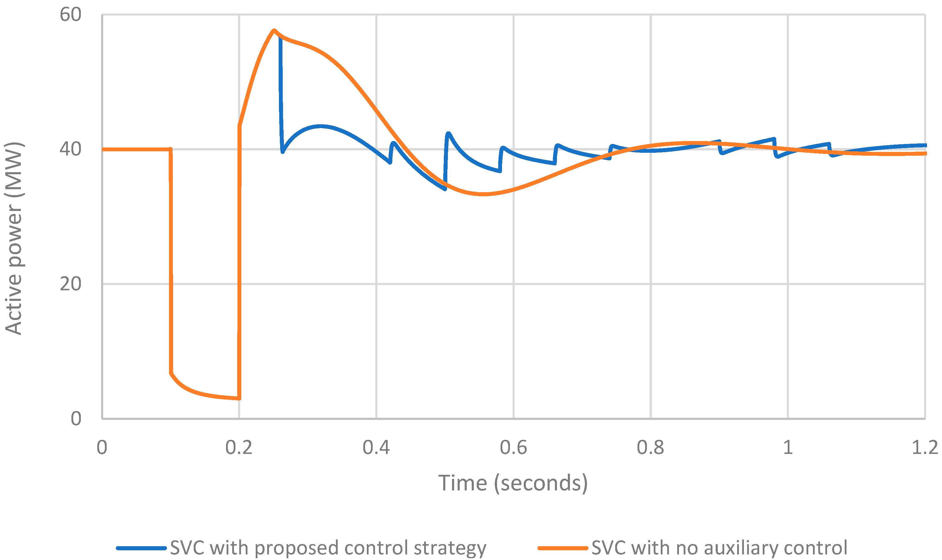
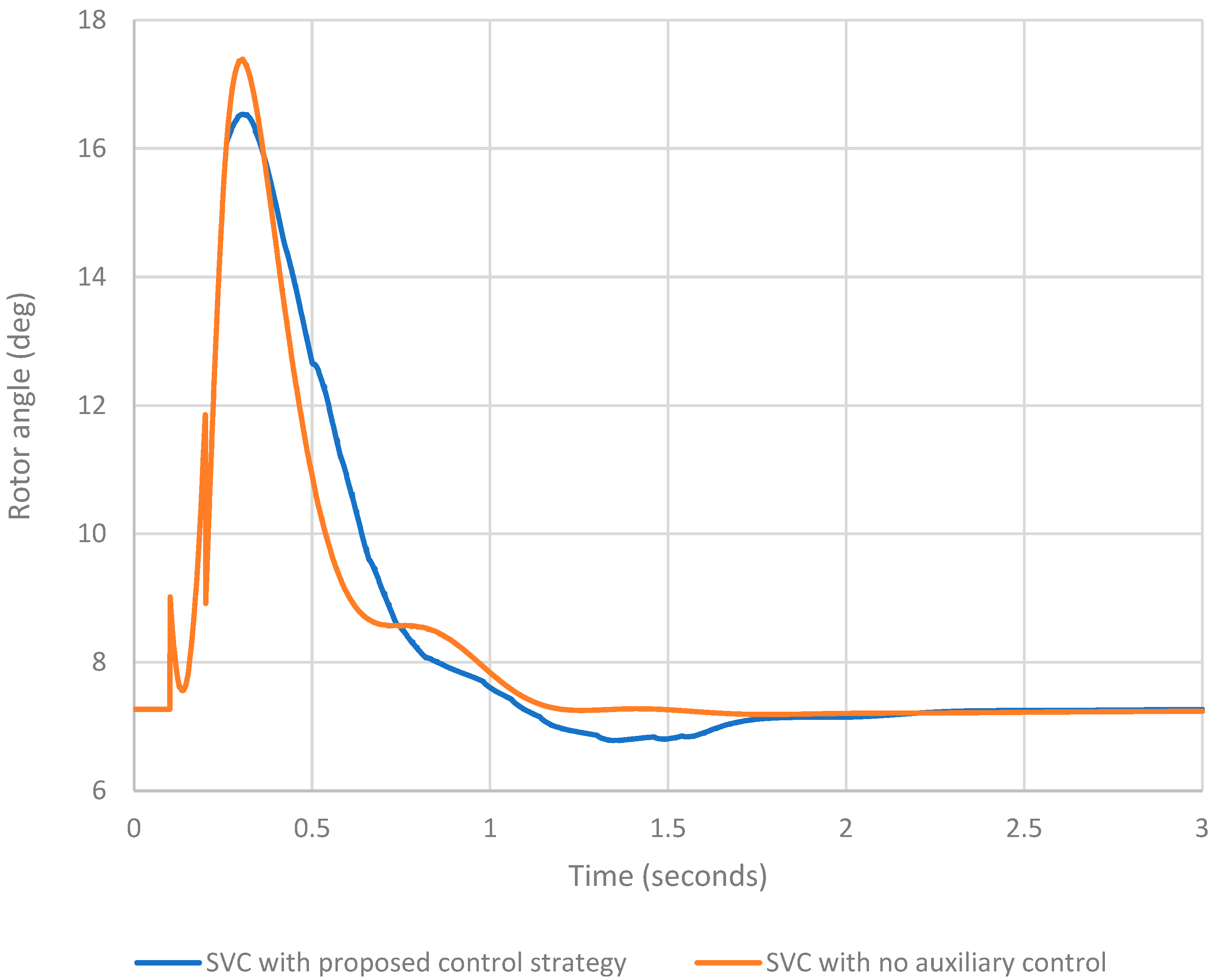
Figure 7 and
Figure 8 show how the SVC affects the active power and rotor angle oscillations of the observed generator. Each figure shows two curves. The blue curve represents the case of the SVC with the proposed control strategy, and the red curve represents the case of the SVC with no auxiliary control.
From
Figure 7, it is evident that the SVC with
adjusted according to
Table 1 reduces the difference between the generator’s mechanical and active power at given moments, and it can be seen from
Figure 8 that it successfully reduces the amplitude and slope of the generator rotor angle oscillation curve.
8. Discussion
This paper presents an SVC control strategy based on collecting voltage phasor measurements through PMUs and calculating the device’s optimal reactive power injection using particle swarm optimization. The PSO algorithm is based on the sensitivity coefficients used to determine the SVC reactive power required for damping the active power oscillations of synchronous generators in fault conditions. This kind of use of sensitivity coefficients was not found in the researched literature.
The main advantage of the proposed strategy is the use of a relatively simple and fast PSO algorithm suitable for real-time SVC control. Another advantage is that the control strategy can be used to simultaneously dampen the rotor angle oscillations of multiple generators in the system by utilizing already installed SVCs and PMUs. The main limitations of the proposed strategy are the sensitivity coefficients that need to be calculated in advance, depending on the network topology in the area of the SVC’s operation. Also, potential delays in PMU measurements can have a negative impact on the accuracy of the PSO output data.
The proposed strategy was tested through simulations in the DIgSILENT PowerFactory 2022 software package on the IEEE 14-bus system. The simulation results showed that an SVC with the proposed control strategy effectively minimized the amplitude of power oscillations during large disturbances, resulting in reduced speed deviations and rotor angle oscillations of generators. Although demonstrated for SVC control, the given strategy can also be used for STATCOM control. To determine the true extent of an SVC’s influence on transient stability, the strategy should be tested on a larger, more realistic system, which will be the focus of future works.


