Review

Application of Low-Resolution Hall Position Sensor in Control and Position Estimation of PMSM—A Review

by
Milad Akrami
1,
Ehsan Jamshidpour
2,
Lotfi Baghli
2,* and
Vincent Frick
1
1
ICube Laboratory, University of Strasbourg/CNRS, 67037 Strasbourg, France
2
Groupe de Recherche en Electrotechnique et Electronique de Nancy (GREEN), Université de Lorraine, 54506 Vandoeuvre-lès-Nancy, France
*
Author to whom correspondence should be addressed.
Energies 2024, 17(17), 4216; https://doi.org/10.3390/en17174216
Submission received: 17 July 2024 / Revised: 10 August 2024 / Accepted: 20 August 2024 / Published: 23 August 2024

Abstract

:
This paper reviews the application of Hall position sensors in control and position estimation of permanent magnet synchronous motors (PMSMs). Accurate rotor position and motor speed data are essential for the high-efficiency control of PMSMs in modern industry. Rotor position and motor speed can be measured by mechanical position sensors, which are costly and less reliable, or by rotor position observers, which are sensitive to system models and changes in motor parameters. This paper examines the benefits, limitations, challenges, and uses of low-resolution Hall position sensors in PMSM drives, presenting them as a cost-effective solution for achieving a balance between performance and expense. In addition, the paper discusses recent solutions to issues related to misplaced Hall position sensors and fault-tolerant control algorithms, and gives an outlook to future developments in this area.

1. Introduction

Permanent magnet (PM) motors have gained popularity in many industrial applications such as electric vehicles, robotics, and high-power applications due to their advantages over brush-type motors. Brushless DC (BLDC) motors and PMSMs are the two main types of PM motors, characterized by trapezoidal and sinusoidal back-EMF voltages, respectively. BLDC motors are traditionally driven using low-resolution Hall-effect position sensors [1,2,3,4].
In many applications, acquiring accurate rotor position and speed information is essential for high-performance drive of PMSMs. Position-acquisition methods for PMSM control systems fall into two main categories. The first category employs high-precision mechanical sensors, such as resolvers and photoelectric encoders, to measure motor speed and rotor position [5]. While these methods offer precise motor control, they increase system volume and cost, are sensitive to environmental conditions, and have reduced reliability due to the possibility of failure during motor operation [5].
The second category determines the rotor position and motor speed data without sensors using methods such as rotor position observers [6], high-frequency signal injection (HFSI) [7], or Kalman filter (KF) approaches [8]. These sensorless methods, however, are sensitive to motor parameter variations, temperature changes, and the nonlinear characteristics of inverters, making accurate speed and position estimation challenging over a wide speed range [2].
Due to their low cost and ability to provide the required speed and rotor position information, the low-resolution Hall position sensors have become a popular alternative to balance performance and cost [9,10,11,12]. Lots of extensive research has been performed on PMSM drives using low-resolution Hall position sensors [13,14,15]. In [14], different techniques for estimating rotor position and motor speed using Hall position sensors were reviewed. Furthermore, ref. [16] evaluates various torque measurement and estimation methods for PMSMs, focusing on Hall-sensor-based approaches in relation to cost, sensitivity to parameter variations, computational time, accuracy, and robustness. The implementation challenges of PMSM control methods utilizing Hall position sensors are explored in [17]. However, these works often lack a comprehensive integration of various perspectives and emerging trends.
This paper extends the review conducted in [1], focusing on the application of Hall position sensors in PMSM drive systems. The organization of the paper is as follows:
  • Section 2 discusses the working principle of Hall-based position sensing and the potential consequences of misplacing Hall sensors.
  • Section 3 presents various estimation methods for rotor position and speed using very low-resolution Hall position sensors.
  • Section 4 explores the application of linear Hall signals in PMSM drives.
  • Section 5 reviews fault-tolerant and fault diagnosis methods based on Hall position signals.
  • Section 6 discusses future trends and recent studies, including fault-tolerant control of PMSMs using Hall position sensors.
  • Finally, Section 7 provides concluding remarks for this review.

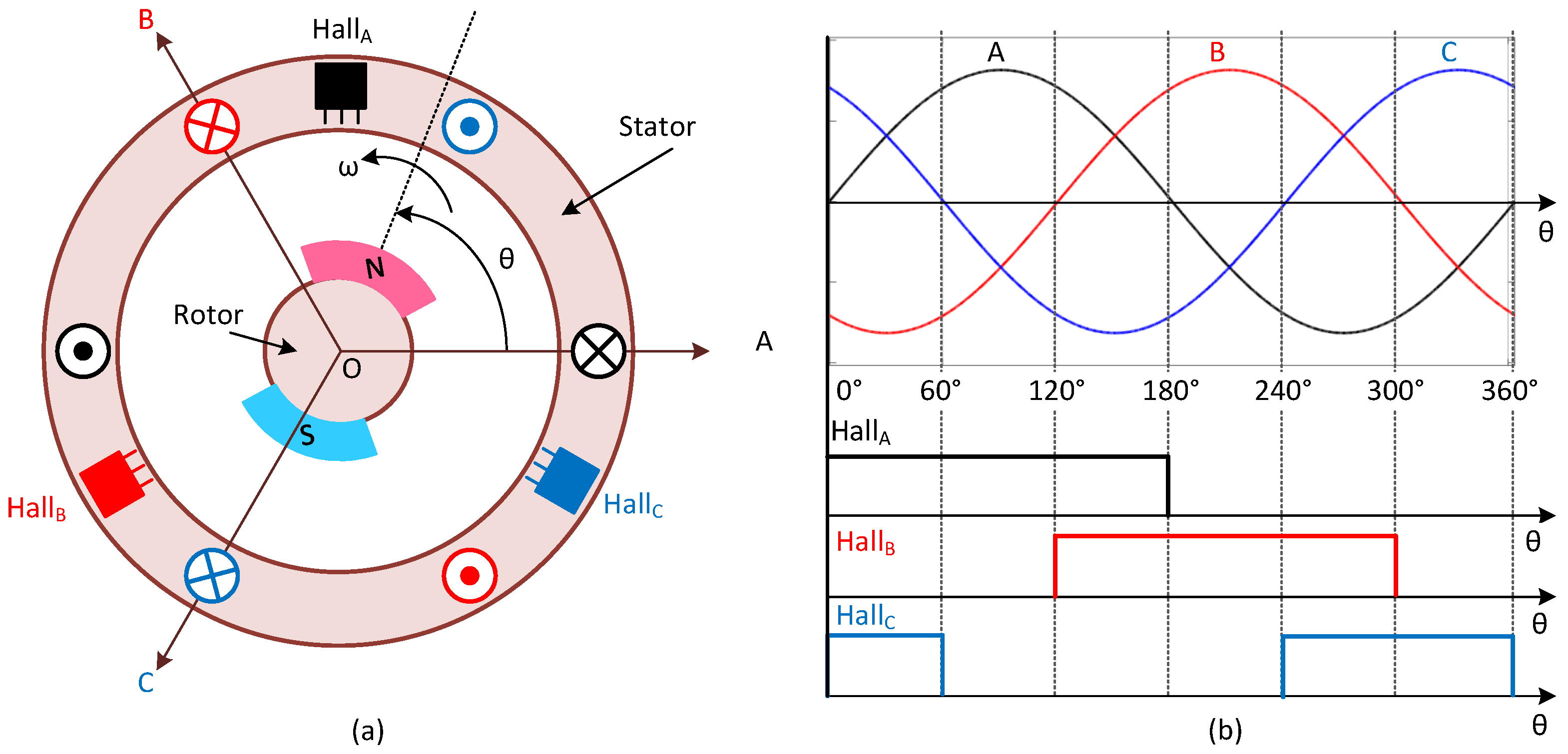
2. Analysis of Hall Position Sensor Signals

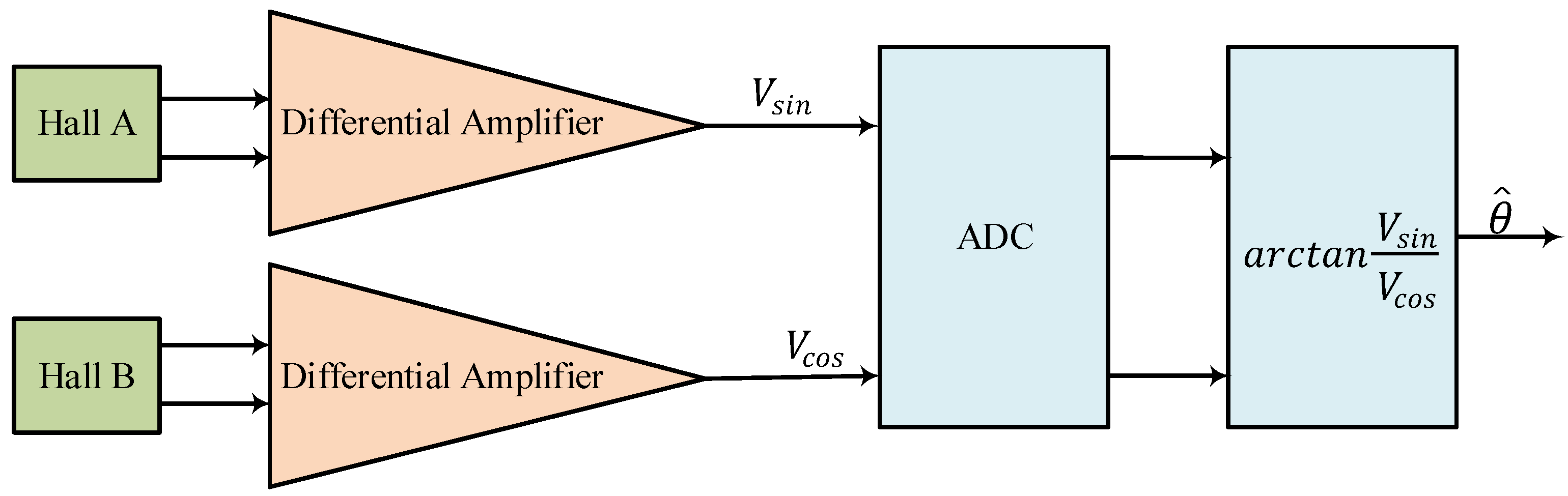
2.1. Working Principle of Hall-Based Position Sensing

Figure 1a depicts the installation positions of three-phase, low-resolution Hall sensors for a single-pole PMSM, labeled as H a l l A , H a l l B , and H a l l C . As the rotor rotates, these Hall sensors generate rectangular waves with frequencies that vary with the rotor’s speed. During one full rotation, three rectangular waves are produced each with a 120° electrical phase difference and a pulse width of 180°. Each 360° electrical cycle is divided into six sections of 60° each, corresponding to different states of the three-phase Hall signal. Figure 1b shows the relationship between these Hall signals and the back-EMF voltages [15]. Continuous rotor position information, derived from these Hall signals, is essential for precise control of the PMSM.

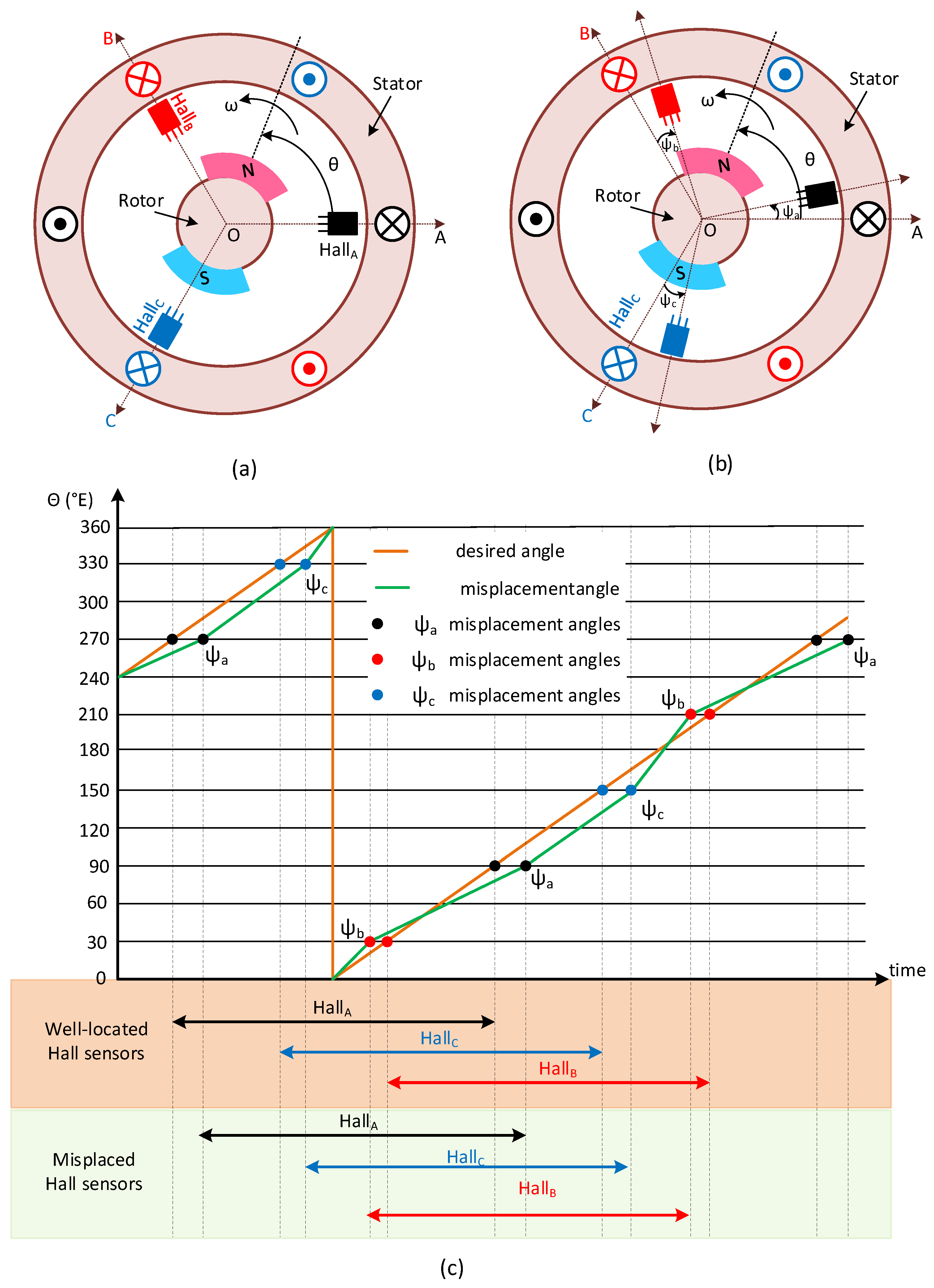
2.2. Consequences of Misplacement of Hall Sensors

Figure 2 illustrates a misplaced installation of the Hall position sensors. This misplacement results in three unequal misplacement angles, denoted as ψ a , ψ b , and ψ c , corresponding to the three phases of the PMSM. Consequently, the inaccurate positioning of the Hall sensors leads to distorted rotor position estimation (see Figure 2c). To prevent harmonic currents, an algorithm is required to correct this distortion. Without such correction, the PMSM will experience low-frequency torque ripples, noise, and vibrations, which affect the performance of the motor [18].
Numerous studies have addressed the problems caused by the misplacement of Hall position sensors in PMSMs. For instance, in [19], a phase-locked loop (PLL) was employed to improve the transient response of a PMSM controlled based on Hall position sensors. However, the design of such observers is intricate and heavily reliant on precise motor parameters.

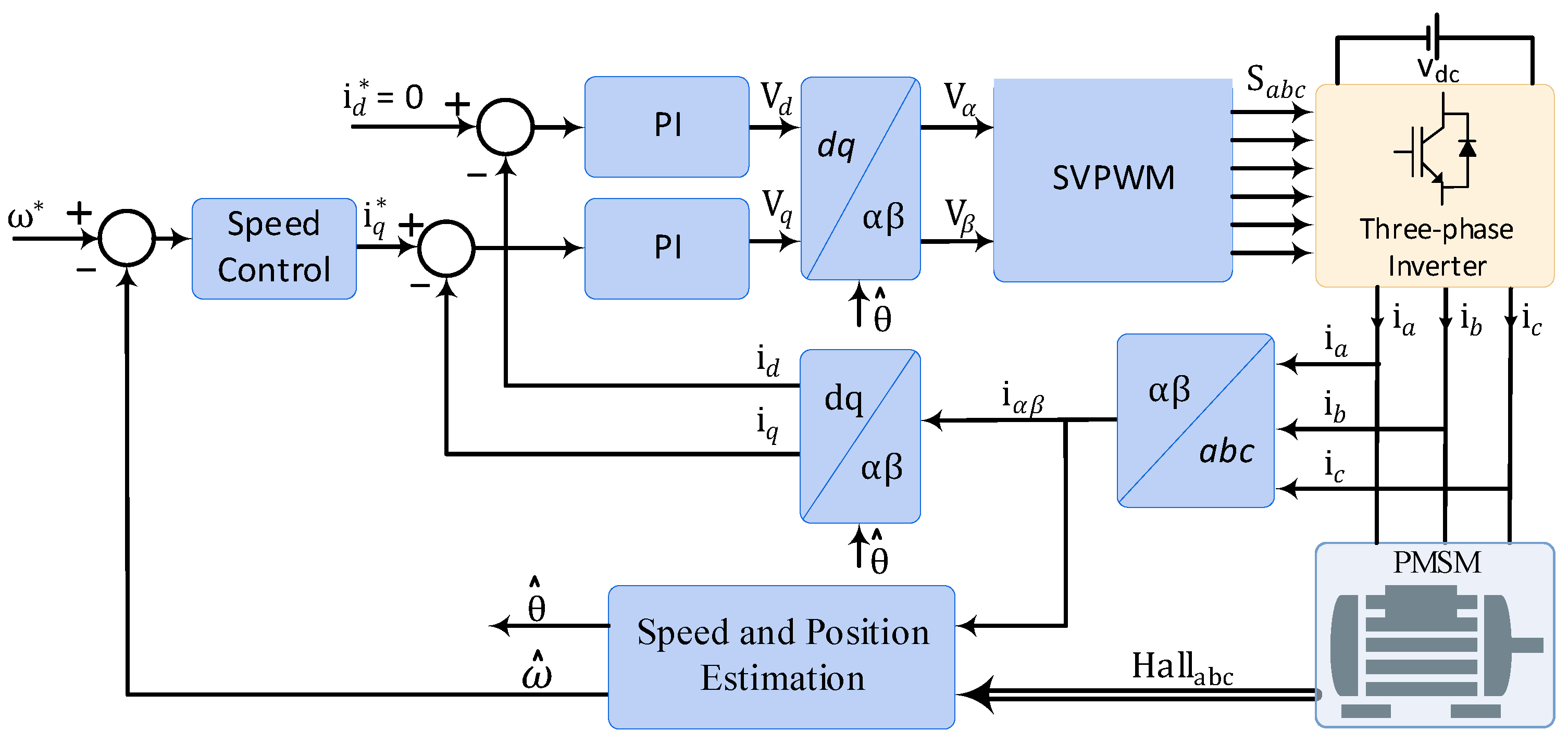
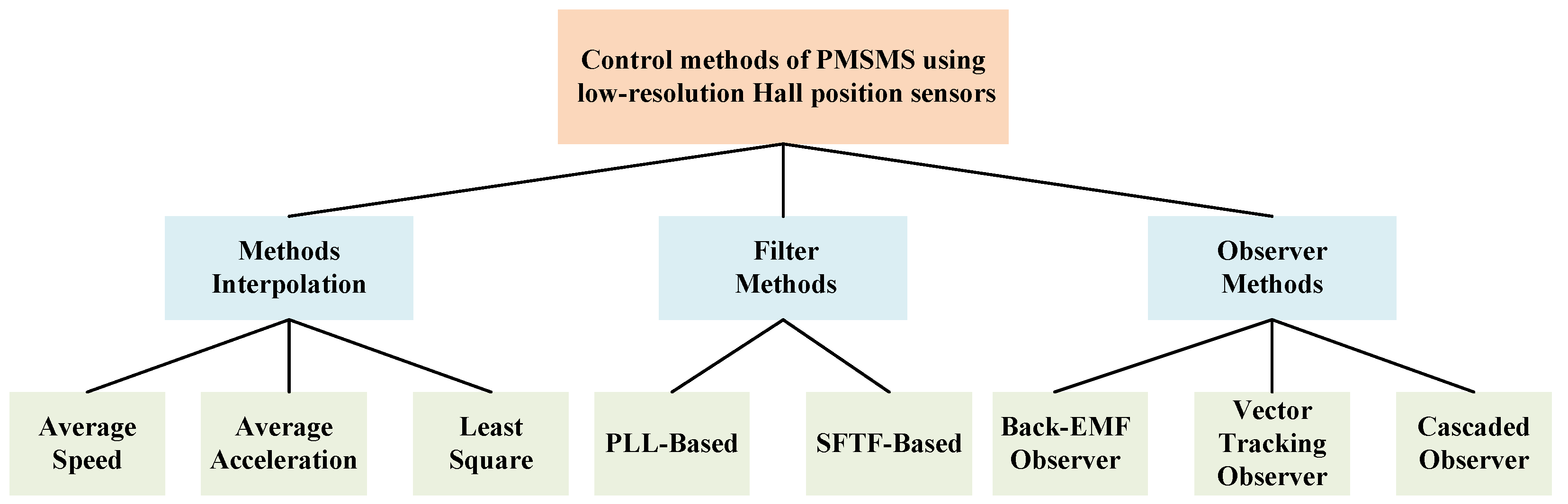
3. Estimation Methods of Motor Speed and Rotor Position

Figure 3 presents the schematic of a PMSM drive system utilizing the field-oriented control (FOC) method with low-resolution Hall position sensors [20]. According to [14], there are three primary methods for estimating speed and position using these sensors: the interpolation method [21], the observer method [22], and the filter method [23].
Although the interpolation and filter methods are straightforward to implement, they can introduce phase lag and noise in a closed-loop speed control system, limiting performance in many PMSM applications. The observer method, on the other hand, allows for more precise estimation of rotor position and speed based on the motor parameters. However, it is also sensitive to variations in these parameters [14]. In addition, several nonlinear position control algorithms have been developed to enhance standstill stability [24,25].

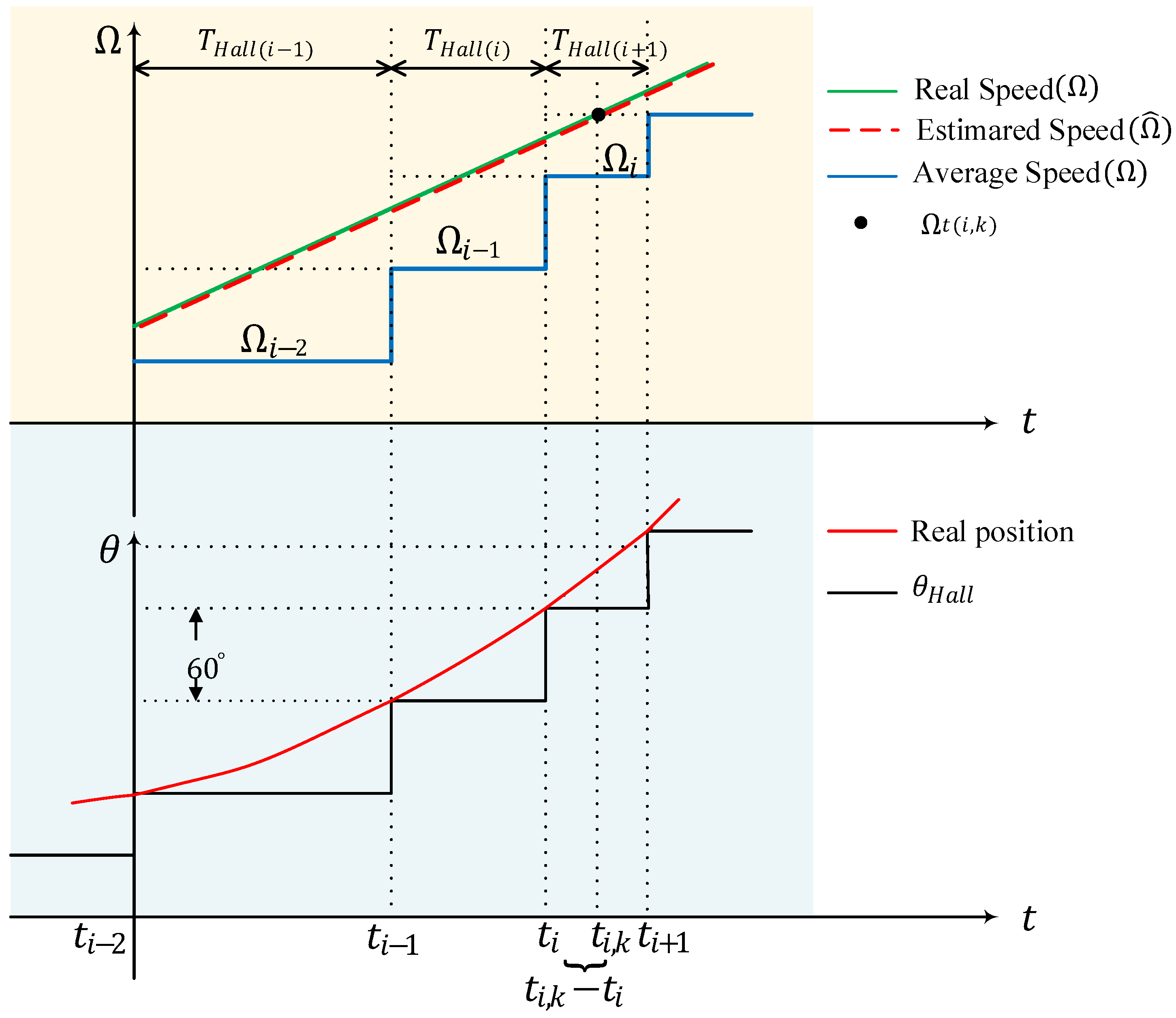
3.1. Interpolation Method
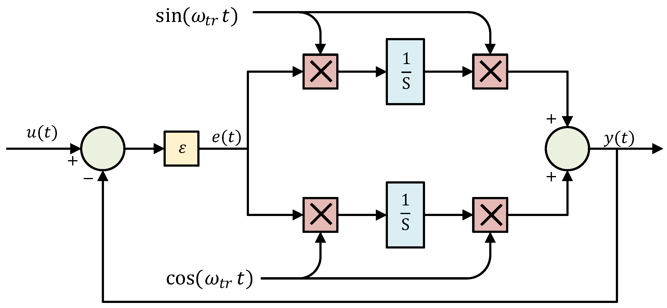
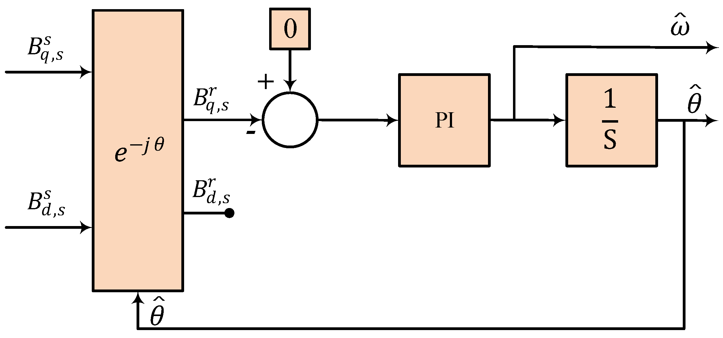
The interpolation method is based on using a discrete function approximation to estimate rotor speed and position by dividing the entire rotational space into six sectors based on the Hall signal states. Within each sector, the rotor speed is assumed to be constant, and continuous rotor position information is derived through interpolation technique [21,26].
According to [14], common Hall signal interpolation methods include the average speed method, the average acceleration method, and the least squares method. The average speed method predicts the rotor position in the subsequent Hall sector using the average velocity determined from the previous Hall sector. Therefore, the method can be expressed based on (1) [20]:
Ω k 1 = π / 3 Δ T θ ^ = θ ( s ) + n T s Ω k 1 ,
here, Δ T is the period of the previous Hall state, θ ( s ) is the measured absolute position in the current Hall sector, n is the number of past sampling points since the start of the current Hall sector, and T s is the sampling period. It should be mentioned that θ ( s ) < θ ^ < θ ( s ) + π / 3 .
Considering the fact that the electrical time constant of the motor is much lower than its mechanical time constant, the speed within each sector is assumed to be constant, despite variations between sectors. However, this method is limited by the deviation in the Hall sensor installation location. Consequently, the motor speed derived from this method can fluctuate significantly, and consequently impacting the accuracy of the rotor position estimation.
To address this issue, average acceleration and moving average interpolation methods have been introduced. The average acceleration method assumes that angular acceleration within each Hall sector remains constant and does not change abruptly when transitioning between sectors [27,28,29]. Also, the process of estimating speed and position from Hall sensor signals using the moving average method is illustrated in Figure 4 and can be calculated by:
a ¯ ( t i ) = Ω ^ ( t i ) Ω ^ ( t i 1 ) T H a l l ( t i ) Ω ^ ( t i , k ) = Ω ^ ( t i ) + a ¯ ( t i ) · ( t i , k t i ) θ 0 ^ ( t i , k ) = θ 0 ^ ( t i ) + Ω ^ ( t i ) · ( t i , k t i ) + 1 2 a ¯ ( t i ) · ( t i , k t i ) 2 ,
where a ¯ ( t i ) denotes the average acceleration at time t i , and θ 0 ^ ( t i , k ) indicates the estimated position at the Hall commutation moment t i .
When speed fluctuations are significant, the average acceleration method can cause rotor pulsation, which negatively impacts system performance. Consequently, this method is unsuitable for applications requiring high dynamic performance. Even though using a higher order of Taylor series expansion can reduce estimation errors, it also complicates software implementation, leading to considerable delays in the estimation results [30].
The least squares method addresses the mechanical installation errors of Hall position sensors [31]. In [32], second-order Taylor linear interpolation is employed to correct the effects of misplaced Hall sensors using the least squares method. Additionally, ref. [33] proposes combining a non-model-based least squares algorithm with a model-based sliding mode observer (SMO) to estimate position and speed, as illustrated in Figure 5.
In this case, six consecutive Hall states are chosen as fitting points, as illustrated in Figure 6. By calculating the continuous position before generating the next Hall state, and adjusting the fitting window as the state changes, the algorithm effectively calculates the continuous position before generation of the next Hall state. Moreover, a continuous position value is constrained to fall between two adjacent Hall states. In [33], a quadratic degree of fitting was selected to strike a balance between efficiency and accuracy. Therefore, the position can be estimated using the polynomial expressed in (3).
θ ^ ( t ) = a 2 t 2 + a 1 t + a 0
where, a 0 , a 1 , and a 2 are the polynomial coefficients that can be calculated based on (4).
6 k = 1 6 t k k = 1 6 t k 2 k = 1 6 t k k = 1 6 t k 2 k = 1 6 t k 3 k = 1 6 t k 2 k = 1 6 t k 3 k = 1 6 t k 4 · a 0 a 1 a 2 = k = 1 6 θ k k = 1 6 t k θ k k = 1 6 t k 2 θ k
One of the challenges of the least-squares method is the lack of sufficient information at start-up.

3.2. Filter Method

The filter method is introduced as an alternative to interpolation, as it does not rely on a function derived from the motion equation of the PMSM. This method utilizes coordinate transformations to convert Hall signals into a Hall rotation vector, containing essential information about the rotor position. Through Fourier decomposition, discrete signals can be analyzed as a combination of sine wave signals. Filtering is subsequently applied to extract fundamental signals from the Hall vectors acquired through coordinate transformations [34].
In [23], improved orthogonal PLLs are proposed that reduce speed ripple, as shown in Figure 7. However, varying electrical frequency in this method can lead to notable drawbacks, such as fluctuations in the low-pass filter (LPF) cutoff frequency and the necessity to adjust adaptive controller parameters. In [35], authors introduce a method that utilizes the harmonic-decomposition complex-coefficient filter-based PLL method. Their approach aims to extract the fundamental Hall vector, facilitating the estimation of the rotor position using a PLL. This method involves adjusting a single parameter, which incorporates an online self-adjustment technique for enhanced performance.
The impact of Hall sensor installation errors on the filter method control of PMSMs is examined in [36]. It utilizes a synchronous frequency tracking filter (SFTF) to extract fundamental signals, as illustrated in Figure 8. The SFTF transfer function can be calculated as follows:
u o u t ( t ) = s i n ( ω t r t ) c o s ( ω t r t ) · s i n ( ω t r t ) e ( t ) d t c o s ( ω t r t ) e ( t ) d t .
where ω t r is the frequency tracked by SFTF.
Using the second derivative of (5), the transfer function of the STFT can be expressed as:
G S F T F = y ( s ) u ( s ) = ε y ( s ) e ( s ) 1 + ε y ( s ) e ( s ) = ε s s 2 + ε s + ω t r 2 .
Therefore, the amplitude-frequency characteristic can be expressed as:
A S F T F ( ω ) = 1 1 + ( ω 2 ω t r 2 ε ω ) 2
Consequently, the SFTF preserves the amplitude of the ω t r frequency while attenuating the amplitudes of other frequencies. In this scenario, ω t r is selected as the fundamental frequency of the input signal [36].
A deadbeat predictive current control method was developed in [37] to enhance the accuracy of rotor speed and position estimation using Hall position sensors. In this method, Hall sensor output signals are converted into Hall vectors containing high-order harmonics through Clarke transformation. An adaptive vectorial filter (AVF) is then used to extract the fundamental waves of the Hall vector. An improved PLL structure is employed to estimate rotor speed and position from these fundamental waves.

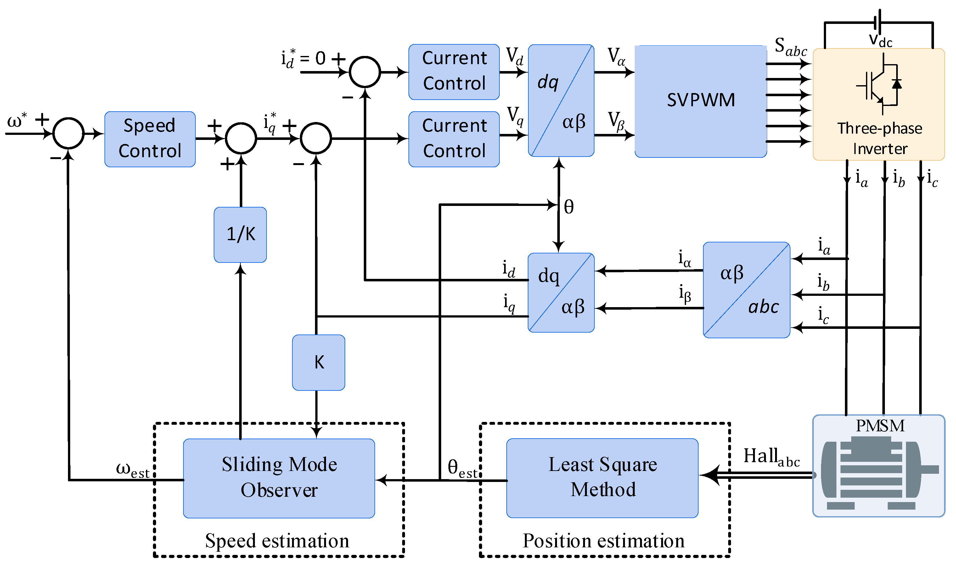
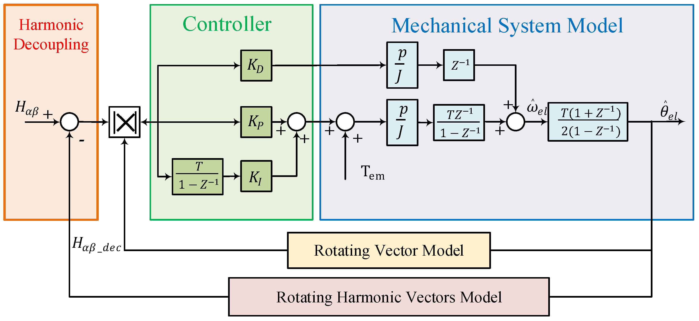
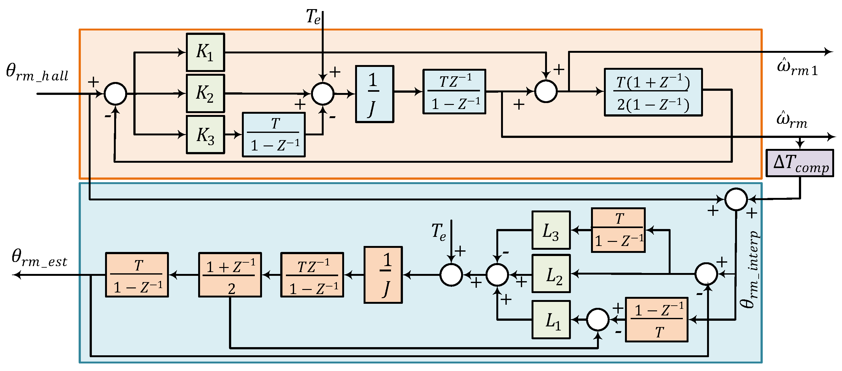
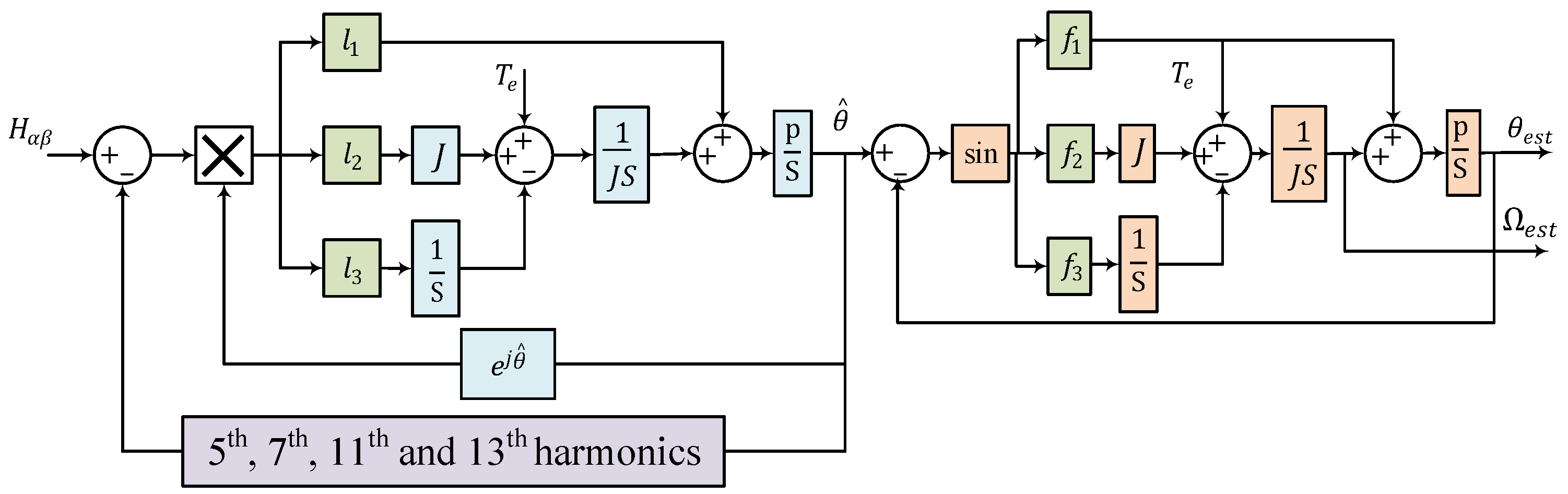
3.3. Observer Method

Implementing previous signal processing methods is relatively straightforward, but they come with challenges such as time delays and increased speed estimation errors. Alternative solutions include state observers [22,38,39] and Kalman filters [40], which are model-based techniques requiring detailed motor information. For example, Luenberger state observers, discussed in [34], use the mechanical parameters of the motor to enhance performance.
One approach, proposed in [41], estimates rotor position using a back-EMF observer combined with low-resolution Hall position signals. Unlike conventional speed observers, this method does not rely on external parameters such as the moment of inertia, avoiding inaccuracies due to inertia errors. It offers robustness to mechanical parameters and is less sensitive to inertia and torque variations. However, accurately determining rotor position at low speeds is difficult because of the low amplitude and frequency of back-EMF voltages. Additionally, the observer’s effectiveness is significantly influenced by the accuracy of current sampling and the signal-to-noise ratio, especially under light load conditions [42].
Another solution is the position vector tracking observer (VTO) for PMSM control with Hall sensors, as proposed in [27,43]. This method facilitates smooth motor startup at low speeds and is less affected by Hall sensor installation errors. However, setting the parameters of the observer system is complex. High controller bandwidth may lead to considerable fluctuations in the observed instantaneous speed and estimated position, while low bandwidth can undermine observer stability [44]. A variation of this method, which includes Fourier decoupling feedback of Hall signals, separates the position vector into fundamental and high-order harmonic components, as detailed in [45]. It has been shown in [45] that the spatial harmonic model for Hall vector in α β -frame ( H α β ) can be expressed as:
H α β = e j ( θ e π 6 ) + k = 1 [ 1 6 k 1 ] e j ( ( 6 k 1 ) θ e + π 6 ) [ + 1 6 k + 1 ] e j ( ( 6 k + 1 ) θ e + π 6 ) ,
where θ e represents the angle between the fundamental vector of H α β and α -axis. Therefore, employing harmonic decoupling (specifically targeting the 5th, 7th, 11th, and 13th harmonics) enables the extraction of the essential fundamental signal necessary for position estimation [45].
The block diagram of the observer incorporating Hall signal feedback decoupling is depicted in Figure 9. A key challenge of this method is selecting the appropriate expansion terms for the discrete Fourier series. Although this approach enables the motor to operate across its full speed range, extending the speed loop bandwidth at low speeds remains problematic in practical applications [45,46].
To enhance the accuracy of rotor speed and position estimation in PMSMs and minimize estimation lag, cascaded observers have been proposed in several studies [47]. One approach is the dual observer method described in [48]. This technique utilizes two cascaded observers, as depicted in Figure 10. The first observer estimates the rotation speed, while the second observer estimates the rotor position. This method proposed two estimation of motor speed, represented by ω ^ r m and ω ^ r m 1 , which their transfer functions are as follows:
ω ^ r m = K 2 s 2 K 3 s J s 3 + J K 1 s 2 + K 2 s K 3 θ r m _ h a l l + s 2 + K 1 s J s 3 + J K 1 s 2 + K 2 s K 3 T e ω ^ r m 1 = J K 1 s 3 + K 2 s 2 K 3 s J s 3 + J K 1 s 2 + K 2 s K 3 θ r m _ h a l l + s 2 J s 3 + J K 1 s 2 + K 2 s K 3 T e ,
where K 1 , K 2 , and K 3 are the controller coefficients. Parameter J is the estimated inertia of the motor. Also, Hall position signal is described by θ r m _ h a l l .
Therefore, based on the transfer function of ω ^ r m , both signals from Hall sensors and torque command signals are filtered by band-pass filters. On the other hand, Hall sensor signals are high-pass filtered, which makes the estimated speed have high-frequency components [48]. The signal θ r m _ i n t e r p , which is output of first observer, is used as the input of the second observer in the cascade structure, is calculated based on (10).
θ r m _ i n t e r p ( k ) = θ r m _ H a l l ( k 1 ) + ω ^ r m ( k ) Δ T c o m p
where, Δ T c o m p represents the time interval between the previously triggered position sensor pulse and the initiation of the estimation algorithm [48].
Compared to the filter method, this approach leverages torque feedforward and provides enhanced frequency characteristics. Unlike feedback decoupling methods, cascaded observers can estimate instantaneous rotor speed and position. However, their industrial application is restricted due to the complex coordination required among observer parameters, motor specifications, and control system settings [49,50]. To overcome these challenges, a cascaded Luenberger observer combined with a feedback decoupling block was proposed in [51]. This approach is designed to reduce low-order noise caused by deviations in Hall position signals, as depicted in Figure 11.
The presented methods for driving PMSMs using very low-resolution Hall position sensors are summarized and compared in Table 1 and Figure 12.

4. Drive of PMSMs Using Linear Hall-Effect Sensors

In the past decades, linear Hall-effect sensors have been proposed as an alternative for driving PMSMs. These sensors offer more precision in determining motor position compared to the low-resolution square-wave Hall sensors [52,53]. As they provide continuous signals, they have been proposed for PMSM drive application.
Two main configurations of linear Hall-effect sensors have been explored in the current literature: some utilize two sensors positioned 90 electrical degrees apart [54,55,56], while others employ three sensors spaced 120 electrical degrees apart [17,57]. In three-sensor configuration, the Hall signals divide the 360 electrical degrees into six intervals. Then, the rotor position can be determined by a PLL [58] or by solving the arcsine function within each interval [59]. However, this method demands more computational resources and cost compared to two-sensor configuration. Within this method, the complex vector B d q , s can be computed using three leakage flux density vectors, B a , B b , and B c , each spaced 120 degrees apart. Subsequently, a PLL can be employed to determine the rotor speed and position data, as depicted in Figure 13 [58].
The linear hall-effect sensor with 90-degree configuration provides two orthogonal signals ( V s i n and V c o s ), which can be used to estimate the rotor speed and position information as expressed in (11) [60], and is illustrated in Figure 14.
θ = a r c t a n V s i n V c o s , V s i n > 0 , V c o s 0 θ = a r c t a n V s i n V c o s + π , V c o s < 0 θ = a r c t a n V s i n V c o s , V s i n 0 , V c o s 0
An approach utilizing the Extended Kalman Filter (EKF) is proposed in [59] to address the errors of position estimation in PMSM drives using linear Hall sensors. However, this analysis does not consider the influence of magnetic field harmonics. Consequently, enhancing the accuracy of rotor position detection and decoding relies on using a high-precision filter to mitigate harmonic components. Furthermore, ref. [60] presents another high-precision rotor position detection method based on the synchronous frequency extractor (SFE), employing two SFEs to extract the fundamental component from linear Hall-effect sensor signals. In [61], a control method based on adaptive notch filter (ANF)-PLL filter is introduced to eliminate third-order harmonics. Another method is proposed in [62] which uses a polynomial of harmonics function utilizing Fast Fourier transform (FFT). Then, a fixed point iteration method is proposed for rotor position estimation. Since this method doesn’t use an LPF, it doesn’t face the delay that LPFs introduce.
The method based on two sensor linear Hall sensors configuration may have amplitude or orthogonal errors due to the air-gap magnetic field generated by the permanent magnetic (PM) ring. Several factors contribute to these errors, including [59,60]:
  • fluctuations in the magnetization of the PMs
  • uneven widths of the PMs
  • variations in air gap temperature
  • eccentricity of the PM ring
  • harmonics within the air-gap magnetic field.
The effects of these factors have been explored in [59], and potential solutions have been proposed for each of them. While using magnets with the same characteristics improves the errors resulting from factors 1 and 2, it also increases production costs. A method proposed in [63] involves optimizing the magnet shape to improve the sinusoidal air-gap magnetic field, and consequently the accuracy of the estimation method based on linear Hall sensors. Temperature is one of the main hindering factors in the application of linear Hall sensors for PMSM applications. Utilizing sensors with temperature compensation or PMs with high temperature stability can mitigate this issue. The effect of temperature on Hall sensors is investigated in [64]. Thermal demagnetization and sensor gain variations are introduced as the two main effects of temperature on the accuracy of Hall-sensor-based position estimation methods. A measurement model is established that accounts for temperature variations. The model is identified using an algorithm that combines particle swarm optimization (PSO) with a successive solving algorithm (SSA). Also, another SSA algorithm with temperature compensation is proposed for real-time position estimation. Another improvement has been proposed by solving the arctan function using the Newton-Raphson method, and finally, at the expense of higher costs, it is possible to increase the number of Hall sensor pairs to address the errors arising from factors 4 and 5 [59].

5. Fault-Tolerant Control of PMSMs Using Hall Sensors

Hall sensors can be damaged by various factors such as temperature fluctuations, vibrations, and exposure to strong magnetic fields [65]. A malfunctioning Hall sensor can lead to speed fluctuations, positional inaccuracies, and mechanical failures. To enhance the reliability of position estimation, fault-tolerant control (FTC) methods have been developed using low-resolution Hall position sensors [66,67].
FTC methods for PMSMs using low-resolution Hall-position sensors have been proposed in previous works [68,69]. The method introduced in [68] combines Hall-sensor based techniques with a sensorless approach, while [69] presents a method based on Fourier transform analysis. However, these methods involve high computational complexity, necessitating additional voltage sensors and the implementation of intricate circuits. This significantly increases the cost and restricts their practicality. As a result, it underscores the primary reason for adopting low-resolution sensor-based control for PMSMs.
An FTC method using only Hall position sensors is suggested in [38]. In [70], a comparison is made between FTC approaches based on the zeroth-order algorithm (ZOA) [9], hybrid observer [71], and VTO methods. The study demonstrates that the VTO method outperforms both ZOA and hybrid observer methods in dynamic performance. This superiority is attributed to the VTO method’s inclusion of an accelerating torque feedforward input and its lower sensitivity to faults compared to the other two methods, which rely on average speed for position estimation. In [72], a hybrid position observer is introduced for online fault detection and fault-tolerant control of PMSMs. A FTC method, incorporating a fault detection technique based on the encoded signals of Hall jump edges, is described in [73]. Additionally, ref. [65] proposes several fault detection methods that rely on Hall signals, including:

5.1. State-Sensitive Fault Diagnosis Method

In this method, the Hall signals ( H A , H B , and H C ) are used to create the variable “S” as described in (12).
S = 4 H A + 2 H B + H C
During normal motor operation, the variable “S” assumes six distinct values in a predetermined sequence, depending on whether the motor turns clockwise (CW) or counterclockwise (CCW). If a Hall sensor malfunctions, “S” takes only four values. Consequently, the system stores and utilizes the last three consecutive “S” values as a lookup table for fault type detection, as depicted in [65]. This state-sensitive fault diagnosis method, also utilized in [72], employs the sum of S n , S n 1 , and S n 2 to detect the type of fault.

5.2. Transition-Sensitive Fault Diagnosis Method

This method is based on the transition of Hall signals. During regular motor operation, six different transition occurs in a predetermined sequence, depending on whether the motor turns CW or CCW. In the event of a Hall sensor malfunction, the number and the sequence of Hall signal transition changes. Consequently, the system retains and utilizes the last two transitions as a lookup table for fault type detection, as illustrated in [65].

5.3. Direction-Sensitive Fault Diagnosis Method

This method relies on observing the state of each sensor at the transition moments of the other two sensors. The principle is that during normal operation, if the signal H x is high (or low) at the rising edge of H y , then H x should be low (or high) at the falling edge of H y ( x , y A , B , C ). The method employs twelve auxiliary variables, denoted as h A , r B , h A , r C , h B , r A , h B , r C , h C , r A , and h C , r B (for each sensor during the rising edge), h A , f B , h A , f C , h B , f A , h B , f C , h C , f A , and h C , f B (for each sensor during the falling edge). These variables can be represented as h x , r y and h x , f y , respectively, as described in [65]:
h x , r y = h x at the rising edge of h y h x , f y = h x at the falling edge of h y .
During normal operation, six variables are in a high state, and the remaining six are in a low state. A new set of twelve variables d x , r y and d x , f y is considered as the estimated direction of h x , r y and h x , f y , respectively. During the normal operation of the system, d x , r y = d x , f y . Therefore, by subtracting the mentioned values, it is possible to reduce the number of variables to six, which can be described as:
| d x , r y d x , f y |
During a fault, it is possible to detect the fault based on the values of (14) using a look-up table [74]. In [75], the method is improved by incorporating an additional parameter ( ε ) determined by the minimum sector duration. This parameter helps to identify fault cases that align closely with the sensor’s edge change turn at the moment of failure. Nevertheless, the threshold coefficient ( ε ) depends on average velocity and acceleration which may result in false alarms under extreme conditions or steep loads [67].

5.4. Binary Fault Diagnosis Method

Since the preceding methods require a specific time lapse between detecting a failure and identifying it, there is a possibility of yielding inaccurate alarms. To address this concern, a method utilizing a binary function is proposed in [67]. This approach considers eight different cases based on the state of the two other Hall signals during the falling and rising edges of the third Hall signal. For instance, the binary fault diagnosis functions for CCW rotation of the motor are detailed in Equation (15).
F A , C C W = ( H A ) · H B + ( H A ) · H ¯ B + H A · H B · H C · ( H C ) + H ¯ A · H ¯ B · H ¯ C · ( H C ) . F B , C C W = ( H B ) · H C + ( H B ) · H ¯ C + H A · H B · H C · ( H A ) + H ¯ A · H ¯ B · H ¯ C · ( H A ) . F C , C C W = ( H C ) · H A + ( H C ) · H ¯ A + H A · H B · H C · ( H B ) + H ¯ A · H ¯ B · H ¯ C · ( H B ) ,
where H x and H x are respectively the rising and falling edges of Hall signals.

6. Future Trends

The low-resolution Hall position sensors offer a balance between cost and performance for position estimation in PMSMs. Comparing these methods with other technologies can provide us with a better understanding of their application in the current industry. Optical encoders provide high-resolution position feedback with high accuracy, making them suitable for precision applications. However, they are more expensive and might be less robust in harsh environments. Resolvers are known for their robustness and ability to operate in extreme conditions and offer high accuracy but they have higher cost and require more complex signal processing for operation.
To summarize, Hall position sensors have advantages including simplicity, cost-effectiveness, and ease of integration, particularly in applications where ultra-high accuracy is not pivotal. Their key feature is the balance of enough accuracy and robustness at a lower cost which make them a practical choice for certain industrial applications.
Concerning Hall-sensor-based methods, it’s important to note that interpolation and filtering are non-model-based approaches for estimating position and speed, providing stable motor control only within a limited speed range, as discussed in [14]. These methods are ideal for applications with relatively constant speeds, such as fans and water pumps, due to their handling of higher frequency harmonic components. In contrast, observer methods with closed-loop characteristics are unaffected by fixed errors in Hall sensor installation. This blend of accuracy and cost-effectiveness has made observer methods widely used in electric vehicles and home appliances.
When implementing these methods in real microcontrollers for mass-production applications, important factors include cost, memory size, processing time, and accuracy of speed estimation during both steady-state and transient conditions. To achieve robust dynamic performance across all speed ranges, closed-loop observers can be improved with parameter identification modules. Moreover, advanced speed estimation techniques can be utilized to reduce system errors and precisely estimate rotor position, ensuring optimal control of PMSMs in applications with a broad operational speed range.
One of the challenges of very low-resolution Hall sensors is their application at low speeds. It is primarily because the method struggles to effectively filter out quantization harmonics which can affect both the speed and torque control loops. Additionally, temperature emerges as a major challenge for linear hall-effect sensors, potentially disrupting position and speed estimations as well as fault-tolerant control methods reliant on these type of sensors. These issues underscore the need for further research for this topic.

7. Conclusions

This paper reviews the application of Hall position sensors in PMSM drives, examining different methods for estimating rotor position and motor speed including interpolation, filtering, and observer-based approaches. The paper reviews their strengths, limitations, challenges, and real-world applications. To summarize Hall-position sensors can provide us with the following advantages:
  • Cost-Effectiveness: Hall position sensors are significantly cheaper than high-resolution encoders or resolvers which makes them popular for low-cost applications.
  • Simplicity and Ease of Integration: These sensors are simpler to integrate into certain applications due to the straightforward design and operation.
  • Robustness: Hall position sensors are more robust against environmental factors such as dust, vibration to improve the performance in harsh industrial environments.
  • Adequate Performance: Even though these sensors are not as precise as high-resolution sensors, they can provide sufficient accuracy for many industrial applications as a trade-off between cost and performance.
Additionally, recent studies regarding the issues associated with incorrect Hall sensor installations and integrating fault-tolerant control strategies into PMSM drives reliant on Hall position sensors have been explored. Additionally, linear Hall-effect sensors have been discussed as an alternative approach for position estimation, offering continuous signals. Finally, the challenges and future trends for Hall position sensors have been discussed. Extracting fundamental signals and filtering out harmonics pose significant challenges, especially when dealing with very low-resolution Hall signals, particularly in low-speed applications. Furthermore, the impact of temperature on the performance of linear Hall-effect sensors is a topic that requires further attention in this field.

Author Contributions

Methodology, M.A.; validation, M.A., E.J., V.F. and L.B.; writing—original draft preparation, M.A.; writing—review and editing, M.A., E.J., V.F. and L.B.; visualization, M.A. and E.J.; supervision, V.F. and E.J. All authors have read and agreed to the published version of the manuscript.

Funding

This research received no external funding.

Conflicts of Interest

The authors declare no conflicts of interest.

Nomenclature

The following abbreviations are used in this manuscript:
BLDCBrushless DC
EKFExtended Kalman Filter
FFTFast Fourier Transform
FOCField-Oriented Control
FTCFault-Tolerant Control
HFSIHigh-Frequency Signal Injection
LPFLow-Pass Filter
PLLPhase-Locked Loop
PMPermanent magnet
PMSMPermanent Magnet Synchronous Motors
SFESynchronous Frequency Extractor
SFTFSynchronous Frequency Tracking Filter
SVPWMSpace Vector Pulse Width Modulation
VTOVector Tracking Observer
B a b c Three-phase Leakage Flux Density Vectors
CWClockwise
CCWCounterclockwise
H a b c Three-phase Hall signals
H α β Hall vector in α β -frame
JMoment of Inertia
i d q Current in dq-frame (in Amperes)
i α β Current in α β -frame (in Amperes)
TsSampling Period
V d q Voltage in dq-frame (in Volts)
V α β Voltage in α β -frame (in Volts)
θ Rotor position (in degrees or radians)
θ ( s ) Measured Absolute Position in The Current Hall Sector
ω Angular velocity (in rad/s)
ψ a b c Three-phase Unequal Misplacement Angles

References

  1. Akrami, M.; Jamshidpour, E.; Frick, V. Application of Hall Position Sensor in Control and Position Estimation of PMSM—A Review. In Proceedings of the 2023 IEEE International Conference on Environment and Electrical Engineering and 2023 IEEE Industrial and Commercial Power Systems Europe (EEEIC/I&CPS Europe), Madrid, Spain, 6–9 June 2023; pp. 1–6. [Google Scholar] [CrossRef]
  2. Muley, N.; Saxena, A.; Chaudhary, P. Comparative Evaluation of Methods for Continuous Rotor Position Estimation using Low Resolution Hall Sensors. In Proceedings of the 2021 National Power Electronics Conference (NPEC), Bhubaneswar, India, 15 December 2021; pp. 1–6. [Google Scholar] [CrossRef]
  3. Liu, X.; Deng, L.; He, Y.; Zhao, J. Control of Permanent-Magnet Synchronous Motor Based on Linear Hall Device. In Proceedings of the 2022 IEEE 5th International Electrical and Energy Conference (CIEEC), Nangjing, China, 27–29 May 2022; pp. 1252–1257. [Google Scholar] [CrossRef]
  4. Akrami, M.; Jamshidpour, E.; Nahid-Mobarakeh, B.; Pierfederici, S.; Frick, V. Sensorless Control Methods for BLDC Motor Drives: A Review. IEEE Trans. Transp. Electrif. 2024. [Google Scholar] [CrossRef]
  5. EL-Refaie, A.M. Fractional-Slot Concentrated-Windings Synchronous Permanent Magnet Machines: Opportunities and Challenges. IEEE Trans. Ind. Electron. 2010, 57, 107–121. [Google Scholar] [CrossRef]
  6. Filho, C.J.V.; Xiao, D.; Vieira, R.P.; Emadi, A. Observers for High-Speed Sensorless PMSM Drives: Design Methods, Tuning Challenges and Future Trends. IEEE Access 2021, 9, 56397–56415. [Google Scholar] [CrossRef]
  7. Wang, G.; Valla, M.; Solsona, J. Position Sensorless Permanent Magnet Synchronous Machine Drives—A Review. IEEE Trans. Ind. Electron. 2020, 67, 5830–5842. [Google Scholar] [CrossRef]
  8. Bolognani, S.; Tubiana, L.; Zigliotto, M. Extended Kalman filter tuning in sensorless PMSM drives. IEEE Trans. Ind. Appl. 2003, 39, 1741–1747. [Google Scholar] [CrossRef]
  9. Morimoto, S.; Sanada, M.; Takeda, Y. Sinusoidal current drive system of permanent magnet synchronous motor with low resolution position sensor. In Proceedings of the IAS ’96. Conference Record of the 1996 IEEE Industry Applications Conference Thirty-First IAS Annual Meeting, San Diego, CA, USA, 6–10 October 1996; Volume 1, pp. 9–14. [Google Scholar] [CrossRef]
  10. Lidozzi, A.; Solero, L.; Crescimbini, F.; Di Napoli, A. SVM PMSM Drive with Low Resolution Hall-Effect Sensors. IEEE Trans. Power Electron. 2007, 22, 282–290. [Google Scholar] [CrossRef]
  11. Jung, S.; Lee, B.; Nam, K. PMSM control based on edge field measurements by Hall sensors. In Proceedings of the 2010 Twenty-Fifth Annual IEEE Applied Power Electronics Conference and Exposition (APEC), Palm Springs, CA, USA, 21–25 February 2010; pp. 2002–2006. [Google Scholar] [CrossRef]
  12. Zaim, S.; Martin, J.P.; Nahid-Mobarakeh, B.; Meibody-Tabar, F. High performance low cost control of a permanent magnet wheel motor using a hall effect position sensor. In Proceedings of the 2011 IEEE Vehicle Power and Propulsion Conference, Chicago, IL, USA, 6–9 September 2011; pp. 1–6. [Google Scholar] [CrossRef]
  13. Ozturk, S.B.; Kivanc, O.C.; Atila, B.; Rehman, S.U.; Akin, B.; Toliyat, H.A. A simple least squares approach for low speed performance analysis of indirect FOC induction motor drive using low-resolution position sensor. In Proceedings of the 2017 IEEE International Electric Machines and Drives Conference (IEMDC), Miami, FL, USA, 21–24 May 2017; pp. 1–8. [Google Scholar] [CrossRef]
  14. Wang, J.; Jiang, Q.; Xiong, D. Review of Rotor Position and Speed Estimation Method of PMSM with Hall Sensor. In Proceedings of the 2021 IEEE 16th Conference on Industrial Electronics and Applications (ICIEA), Chengdu, China, 1–4 August 2021; pp. 1832–1837. [Google Scholar] [CrossRef]
  15. An, Q.; Chen, C.; Zhao, M.; Ma, T.; Ge, K. Research on Rotor Position Estimation of PMSM Based on Hall Position Sensor. In Proceedings of the 2021 IEEE 16th Conference on Industrial Electronics and Applications (ICIEA), Chengdu, China, 1–4 August 2021; pp. 2088–2094. [Google Scholar] [CrossRef]
  16. Alonso, D.F.; Kang, Y.; Fernandez Laborda, D.; Gomez, M.M.; Reigosa, D.D.; Briz, F. Permanent Magnet Synchronous Machine Torque Estimation Using Low Cost Hall-Effect Sensors. IEEE Trans. Ind. Appl. 2021, 57, 3735–3743. [Google Scholar] [CrossRef]
  17. Reigosa, D.; Fernandez, D.; González, C.; Lee, S.B.; Briz, F. Permanent Magnet Synchronous Machine Drive Control Using Analog Hall-Effect Sensors. IEEE Trans. Ind. Appl. 2018, 54, 2358–2369. [Google Scholar] [CrossRef]
  18. Miguel-Espinar, C.; Heredero-Peris, D.; Igor-Gross, G.; Llonch-Masachs, M.; Montesinos-Miracle, D. Accurate Angle Representation from Misplaced Hall-Effect Switch Sensors for Low-Cost Electric Vehicle Applications. IEEE Trans. Ind. Appl. 2022, 58, 5227–5237. [Google Scholar] [CrossRef]
  19. Cortajarena, J.; García, S.; Cortajarena, J.; Barambones, O.; Alkorta, P. Influence of the rotor angle precision in control of IPMSM drives and improvement method using sensorless estimator with Hall sensors. IET Power Electron. 2019, 12, 383–391. [Google Scholar] [CrossRef]
  20. Xu, X.; Huang, X.; Li, Z. An Improved Rotor Position Estimation Method for PMSM Using Low-Resolution Hall-Effect Sensors. In Proceedings of the 2022 IEEE Transportation Electrification Conference and Expo, Asia-Pacific (ITEC Asia-Pacific), Haining, China, 28–31 October 2022; pp. 1–4. [Google Scholar] [CrossRef]
  21. Bae, B.H.; Sul, S.K.; Kwon, J.H.; Byeon, J.S. Implementation of sensorless vector control for super-high-speed PMSM of turbo-compressor. IEEE Trans. Ind. Appl. 2003, 39, 811–818. [Google Scholar] [CrossRef]
  22. Yoo, A.; Sul, S.K.; Lee, D.C.; Jun, C.S. Novel Speed and Rotor Position Estimation Strategy Using a Dual Observer for Low-Resolution Position Sensors. IEEE Trans. Power Electron. 2009, 24, 2897–2906. [Google Scholar] [CrossRef]
  23. Zhao, Y.; Huang, W.; Yang, J.; Bu, F.; Liu, S. A PMSM rotor position estimation with low-cost Hall-effect sensors using improved PLL. In Proceedings of the 2016 IEEE Transportation Electrification Conference and Expo, Asia-Pacific (ITEC Asia-Pacific), Busan, Republic of Korea, 1–4 June 2016; pp. 804–807. [Google Scholar] [CrossRef]
  24. Zheng, X.; Tiecai, L.; Yongping, L.; Bingyi, G. Position-measuring error analysis and solution of hall sensor in pseudo-sensorless PMSM driving system. In Proceedings of the IECON’03. 29th Annual Conference of the IEEE Industrial Electronics Society (IEEE Cat. No.03CH37468), Roanoke, VA, USA, 2–6 November 2003; Volume 2, pp. 1337–1342. [Google Scholar] [CrossRef]
  25. Ni, Q.; Yang, M.; Odhano, S.A.; Tang, M.; Zanchetta, P.; Liu, X.; Xu, D. A New Position and Speed Estimation Scheme for Position Control of PMSM Drives Using Low-Resolution Position Sensors. IEEE Trans. Ind. Appl. 2019, 55, 3747–3758. [Google Scholar] [CrossRef]
  26. Ko, A.Y.; Kim, D.Y.; Won, I.K.; Kim, Y.R.; Won, C.Y. Interpolation error compensation method for look-up table based IPMSM drive. In Proceedings of the 2014 IEEE Conference and Expo Transportation Electrification Asia-Pacific (ITEC Asia-Pacific), Beijing, China, 31 August–3 September 2014; pp. 1–5. [Google Scholar] [CrossRef]
  27. Giulii Capponi, F.; De Donato, G.; Del Ferraro, L.; Honorati, O.; Harke, M.; Lorenz, R. AC brushless drive with low-resolution Hall-effect sensors for surface-mounted PM Machines. IEEE Trans. Ind. Appl. 2006, 42, 526–535. [Google Scholar] [CrossRef]
  28. Baris Ozturk, S.; Akin, B.; Toliyat, H.; Ashrafzadeh, F. Low-cost direct torque control of permanent magnet synchronous motor using Hall-effect sensors. In Proceedings of the Twenty-First Annual IEEE Applied Power Electronics Conference and Exposition (APEC ’06), Dallas, TX, USA, 19–23 March 2006. [Google Scholar] [CrossRef]
  29. Kreindler, L.; Iacob, I.; Casaru, G.; Sarca, A.; Olteanu, R.; Matianu, D. PMSM drive using digital hall position sensors for light EV applications. In Proceedings of the 2015 9th International Symposium on Advanced Topics in Electrical Engineering (ATEE), Bucharest, Romania, 7–9 May 2015; pp. 199–204. [Google Scholar] [CrossRef]
  30. Kim, H.; Harke, M.; Lorenz, R. Sensorless control of interior permanent magnet machine drives with zero-phase-lag position estimation. In Proceedings of the Conference Record of the 2002 IEEE Industry Applications Conference. 37th IAS Annual Meeting (Cat. No.02CH37344), Pittsburgh, PA, USA, 13–18 October 2002; Volume 3, pp. 1661–1667. [Google Scholar] [CrossRef]
  31. Brown, R.; Schneider, S.; Mulligan, M. Analysis of algorithms for velocity estimation from discrete position versus time data. IEEE Trans. Ind. Electron. 1992, 39, 11–19. [Google Scholar] [CrossRef]
  32. Zhang, X.; Zhang, W. An improved rotor position estimation in PMSM with low-resolution hall-effect sensors. In Proceedings of the 2014 17th International Conference on Electrical Machines and Systems (ICEMS), Hangzhou, China, 22–25 October 2014; pp. 2722–2727. [Google Scholar] [CrossRef]
  33. Dan, H.; Zeng, S.; Liu, Y.; Sun, Y.; Su, M. An Improved Position and Speed Estimation Scheme for Permanent Magnet Synchronous Motor with Low-Cost Hall Sensors. In Proceedings of the 2022 IEEE 5th International Electrical and Energy Conference (CIEEC), Nangjing, China, 27–29 May 2022; pp. 1831–1836. [Google Scholar] [CrossRef]
  34. Kovudhikulrungsri, L.; Koseki, T. Precise Speed Estimation from a Low-Resolution Encoder by Dual-Sampling-Rate Observer. IEEE/ASME Trans. Mechatron. 2006, 11, 661–670. [Google Scholar] [CrossRef]
  35. Xin, Z.Z.; Wang, J.J.; Zhao, H.J. Rotor Position Estimation Using Harmonic-Decomposition Complex-Coefficient Filter-Based PLL for PMSM with Switch Hall-Effect Sensors. IEEE J. Emerg. Sel. Top. Power Electron. 2024, 12, 2249–2259. [Google Scholar] [CrossRef]
  36. Liu, G.; Chen, B.; Song, X. High-Precision Speed and Position Estimation Based on Hall Vector Frequency Tracking for PMSM with Bipolar Hall-Effect Sensors. IEEE Sens. J. 2019, 19, 2347–2355. [Google Scholar] [CrossRef]
  37. Yao, X.; Huang, S.; Wang, J.; Zhang, F.; Wang, Y.; Ma, H. Pseudo Sensorless Deadbeat Predictive Current Control for PMSM Drives with Hall-Effect Sensors. In Proceedings of the 2021 IEEE International Electric Machines & Drives Conference (IEMDC), Hartford, CT, USA, 17–20 May 2021; pp. 1–6. [Google Scholar] [CrossRef]
  38. Scelba, G.; De Donato, G.; Scarcella, G.; Giulii Capponi, F.; Bonaccorso, F. Fault-Tolerant Rotor Position and Velocity Estimation Using Binary Hall-Effect Sensors for Low-Cost Vector Control Drives. IEEE Trans. Ind. Appl. 2014, 50, 3403–3413. [Google Scholar] [CrossRef]
  39. De Donato, G.; Scelba, G.; Pulvirenti, M.; Scarcella, G.; Giulii Capponi, F. Low-Cost, High-Resolution, Fault-Robust Position and Speed Estimation for PMSM Drives Operating in Safety-Critical Systems. IEEE Trans. Power Electron. 2019, 34, 550–564. [Google Scholar] [CrossRef]
  40. Shi, T.; Wang, Z.; Xia, C. Speed Measurement Error Suppression for PMSM Control System Using Self-Adaption Kalman Observer. IEEE Trans. Ind. Electron. 2015, 62, 2753–2763. [Google Scholar] [CrossRef]
  41. Batzel, T.; Lee, K. Commutation torque ripple minimization for permanent magnet synchronous machines with Hall effect position feedback. IEEE Trans. Energy Convers. 1998, 13, 257–262. [Google Scholar] [CrossRef]
  42. Liu, Y.; Zhao, J.; Xia, M.; Luo, H. Model Reference Adaptive Control-Based Speed Control of Brushless DC Motors with Low-Resolution Hall-Effect Sensors. IEEE Trans. Power Electron. 2014, 29, 1514–1522. [Google Scholar] [CrossRef]
  43. Kim, S.Y.; Choi, C.; Lee, K.; Lee, W. An Improved Rotor Position Estimation with Vector-Tracking Observer in PMSM Drives with Low-Resolution Hall-Effect Sensors. IEEE Trans. Ind. Electron. 2011, 58, 4078–4086. [Google Scholar] [CrossRef]
  44. Harke, M.C.; Donato, G.D.; Capponi, F.G.; Tesch, T.; Lorenz, R. Implementation Issues and Performance Evaluation of Surface-Mounted PM Machine Drives with Hall-Effect Position Sensors and a Vector-Tracking Observer. In Proceedings of the Conference Record of the 2006 IEEE Industry Applications Conference Forty-First IAS Annual Meeting, Tampa, FL, USA, 8–12 October 2006; Volume 4, pp. 1621–1628. [Google Scholar] [CrossRef]
  45. Harke, M.C.; De Donato, G.; Giulii Capponi, F.; Tesch, T.R.; Lorenz, R.D. Implementation Issues and Performance Evaluation of Sinusoidal, Surface-Mounted PM Machine Drives with Hall-Effect Position Sensors and a Vector-Tracking Observer. IEEE Trans. Ind. Appl. 2008, 44, 161–173. [Google Scholar] [CrossRef]
  46. Scelba, G.; De Donato, G.; Pulvirenti, M.; Giulii Capponi, F.; Scarcella, G. Hall-Effect Sensor Fault Detection, Identification, and Compensation in Brushless DC Drives. IEEE Trans. Ind. Appl. 2016, 52, 1542–1554. [Google Scholar] [CrossRef]
  47. Comanescu, M. Speed, rotor position and load torque estimation of the PMSM using an extended dynamic model and cascaded sliding mode observers. In Proceedings of the 2016 International Symposium on Power Electronics, Electrical Drives, Automation and Motion (SPEEDAM), Capri, Italy, 22–24 June 2016; pp. 98–103. [Google Scholar] [CrossRef]
  48. Yoo, A.; Sul, S.K.; Lee, D.C.; Seung, C. Novel speed and rotor position estimation strategy using a dual observer for low resolution position sensors. In Proceedings of the 2008 IEEE Power Electronics Specialists Conference, Rhodes, Greece, 15–19 June 2008; pp. 647–653. [Google Scholar] [CrossRef]
  49. Ahmed-Ali, T.; Cherrier, E.; M’Saad, M. Cascade high gain observers for nonlinear systems with delayed output measurement. In Proceedings of the 48h IEEE Conference on Decision and Control (CDC) held jointly with 2009 28th Chinese Control Conference, Shanghai, China, 15–18 December 2009; pp. 8226–8231. [Google Scholar] [CrossRef]
  50. Ni, Q.; Yang, M.; Dong, X.; Liu, X.; Xu, D. State Estimation Error Suppression for PMSM Speed Observer Based on Hall Position Sensor. Diangong Jishu Xuebao/Transactions China Electrotech. Soc. 2017, 32, 189–198. [Google Scholar] [CrossRef]
  51. Zhao, M.; An, Q.; Chen, C.; Cao, F.; Li, S. Observer Based Improved Position Estimation in Field-Oriented Controlled PMSM with Misplaced Hall-Effect Sensors. Energies 2022, 15, 5985. [Google Scholar] [CrossRef]
  52. Kim, J.; Kim, M.H.; Cho, K.; Choi, S. Dual sampling rate observer for motor position estimation using linear hall sensors and iterative algorithm. In Proceedings of the 2016 19th International Conference on Electrical Machines and Systems (ICEMS), Chiba, Japan, 13–16 November 2016; pp. 1–4. [Google Scholar]
  53. Yu, Z.; Qin, M.; Chen, X.; Meng, L.; Huang, Q.; Fu, C. Computationally Efficient Coordinate Transformation for Field-Oriented Control Using Phase Shift of Linear Hall-Effect Sensor Signals. IEEE Trans. Ind. Electron. 2020, 67, 3442–3451. [Google Scholar] [CrossRef]
  54. Yan, L.; Ye, P.; Zhang, C.; Zhang, H. An improved position detection method for permanent magnet linear motor using linear hall sensors. In Proceedings of the 2017 20th International Conference on Electrical Machines and Systems (ICEMS), Sydney, NSW, Australia, 11–14 August 2017; pp. 1–4. [Google Scholar] [CrossRef]
  55. Fernandez, D.; Fernandez, D.; Martinez, M.; Reigosa, D.; Diez, A.B.; Briz, F. Resolver Emulation for PMSMs Using Low Cost Hall-Effect Sensors. IEEE Trans. Ind. Appl. 2020, 56, 4977–4985. [Google Scholar] [CrossRef]
  56. Luu, P.T.; Lee, J.Y.; Kim, J.W.; Chung, S.U.; Kwon, S.M. Magnetic Sensor Design for a Permanent Magnet Linear Motor Considering Edge-Effect. IEEE Trans. Ind. Electron. 2020, 67, 5768–5777. [Google Scholar] [CrossRef]
  57. Caricchi, F.; Capponi, F.; Crescimbini, F.; Solero, L. Sinusoidal brushless drive with low-cost linear Hall effect position sensors. In Proceedings of the 2001 IEEE 32nd Annual Power Electronics Specialists Conference (IEEE Cat. No.01CH37230), Vancouver, BC, Canada, 7–21 June 2001; Volume 2, pp. 799–804. [Google Scholar] [CrossRef]
  58. Fernandez, D.; Reigosa, D.; Park, Y.; Lee, S.; Briz, F. Hall-Effect Sensors as Multipurpose Devices to Control, Monitor and Diagnose AC Permanent Magnet Synchronous Machines. In Proceedings of the 2021 IEEE Energy Conversion Congress and Exposition (ECCE), Vancouver, BC, Canada, 10–14 October 2021; pp. 4967–4972. [Google Scholar] [CrossRef]
  59. Hu, J.; Zou, J.; Xu, F.; Li, Y.; Fu, Y. An Improved PMSM Rotor Position Sensor Based on Linear Hall Sensors. IEEE Trans. Magn. 2012, 48, 3591–3594. [Google Scholar] [CrossRef]
  60. Song, X.; Fang, J.; Han, B. High-Precision Rotor Position Detection for High-Speed Surface PMSM Drive Based on Linear Hall-Effect Sensors. IEEE Trans. Power Electron. 2016, 31, 4720–4731. [Google Scholar] [CrossRef]
  61. Jung, S.Y.; Nam, K. PMSM Control Based on Edge-Field Hall Sensor Signals Through ANF-PLL Processing. IEEE Trans. Ind. Electron. 2011, 58, 5121–5129. [Google Scholar] [CrossRef]
  62. Kim, J.; Choi, S.; Cho, K.; Nam, K. Position Estimation Using Linear Hall Sensors for Permanent Magnet Linear Motor Systems. IEEE Trans. Ind. Electron. 2016, 63, 7644–7652. [Google Scholar] [CrossRef]
  63. Li, Y.; Zou, J.; Lu, Y. Optimum design of magnet shape in permanent-magnet synchronous motors. IEEE Trans. Magn. 2003, 39, 3523–3526. [Google Scholar] [CrossRef]
  64. Zhang, C.; Li, B.; Ye, P.; Zhang, H. Analog-Hall-Sensor-Based Position Detection Method with Temperature Compensation for Permanent-Magnet Linear Motor. IEEE Trans. Instrum. Meas. 2021, 70, 1–11. [Google Scholar] [CrossRef]
  65. Dong, L.; Jatskevich, J.; Huang, Y.; Chapariha, M.; Liu, J. Fault Diagnosis and Signal Reconstruction of Hall Sensors in Brushless Permanent Magnet Motor Drives. IEEE Trans. Energy Convers. 2016, 31, 118–131. [Google Scholar] [CrossRef]
  66. Zhao, Y.; Huang, W.; Yang, J. Fault diagnosis of low-cost hall-effect sensors used in controlling permanent magnet synchronous motor. In Proceedings of the 2016 19th International Conference on Electrical Machines and Systems (ICEMS), Chiba, Japan, 13–16 November 2017; pp. 1–5. [Google Scholar]
  67. Mousmi, A.; Abbou, A.; El Houm, Y. Binary Diagnosis of Hall Effect Sensors in Brushless DC Motor Drives. IEEE Trans. Power Electron. 2020, 35, 3859–3868. [Google Scholar] [CrossRef]
  68. Jeong, Y.S.; Sul, S.K.; Schulz, S.; Patel, N. Fault detection and fault-tolerant control of interior permanent-magnet motor drive system for electric vehicle. IEEE Trans. Ind. Appl. 2005, 41, 46–51. [Google Scholar] [CrossRef]
  69. Tashakori, A.; Ektesabi, M. A simple fault tolerant control system for Hall Effect sensors failure of BLDC motor. In Proceedings of the 2013 IEEE 8th Conference on Industrial Electronics and Applications (ICIEA), Melbourne, VIC, Australia, 19–21 June 2013; pp. 1011–1016. [Google Scholar] [CrossRef]
  70. Scelba, G.; De Donato, G.; Pulvirenti, M.; Capponi, F.G.; Scarcella, G. Hall-effect sensor fault detection, identification an compensation in brushless DC drives. In Proceedings of the 2015 IEEE Energy Conversion Congress and Exposition (ECCE), Montreal, QC, Canada, 20–24 September 2015; pp. 3987–3995. [Google Scholar] [CrossRef]
  71. Corzine, K.; Sudhoff, S. A hybrid observer for high performance brushless DC motor drives. IEEE Trans. Energy Convers. 1996, 11, 318–323. [Google Scholar] [CrossRef]
  72. Guo, C.; Gao, X.; Zhang, Q.; Zhu, Y. Fault Tolerance Method of Low-Resolution Hall Sensor in Permanent Magnet Synchronous Machine. IEEE Access 2022, 10, 119162–119169. [Google Scholar] [CrossRef]
  73. Huang, Y.; Zhao, M.; Zhang, J.; Lu, M. The Hall Sensors Fault-Tolerant for PMSM Based on Switching Sensorless Control with PI Parameters Optimization. IEEE Access 2022, 10, 114048–114059. [Google Scholar] [CrossRef]
  74. Dong, L.; Huang, Y.; Jatskevich, J.; Liu, J. Improved Fault-Tolerant Control for Brushless Permanent Magnet Motor Drives with Defective Hall Sensors. IEEE Trans. Energy Convers. 2016, 31, 789–799. [Google Scholar] [CrossRef]
  75. Zhang, Q.; Feng, M. Fast Fault Diagnosis Method for Hall Sensors in Brushless DC Motor Drives. IEEE Trans. Power Electron. 2019, 34, 2585–2596. [Google Scholar] [CrossRef]
Figure 1. (a) Low-resolution square-wave Hall position sensors for a single-pole PMSM ( θ : rotor position, ω : rotor speed). (b) Diagram showing the correspondence between Hall signals and motor back-EMF voltages.
Energies 17 04216 g001
Figure 2. Impact of Hall sensor installation: (a) Well-placed Hall sensors, (b) Misplaced Hall sensors, (c) Diagram illustrating the signals from misplaced Hall position sensors for a PMSM, leading to three unequal misalignment angles [18].
Energies 17 04216 g002
Figure 3. Schematic of a PMSM drive using low-resolution Hall-position sensors [20].
Energies 17 04216 g003
Figure 4. Estimating speed and position using the moving average method [29].
Energies 17 04216 g004
Figure 5. Block diagram of PMSM drive using Hall position sensors based on incorporating least square algorithm and SMO method [33].
Energies 17 04216 g005
Figure 6. Least square fitting of discrete Hall signals [33].
Energies 17 04216 g006
Figure 7. Block diagram of a filter-based improved PLL based on Hall signals [23].
Energies 17 04216 g007
Figure 8. Block diagram of SFTF [36].
Energies 17 04216 g008
Figure 9. Schematic of VTO control method [45].
Energies 17 04216 g009
Figure 10. Schematic of a cascade observer to estimate speed and rotor position of a PMSM [48].
Energies 17 04216 g010
Figure 11. Cascaded dual Luenberger observer [51].
Energies 17 04216 g011
Figure 12. Control methods of PMSMs using low-resolution Hall position sensors.
Energies 17 04216 g012
Figure 13. Block diagram of a PLL-based position estimation method based on three Hall sensors configuration [58].
Energies 17 04216 g013
Figure 14. Position estimation method based on two linear hall-effect sensors configuration using arctan function [60].
Energies 17 04216 g014
Table 1. Comparison of different control methods of PMSMs using low-resolution Hall position sensors.
MethodTechniqueAdvantagesDrawbacks
Interpolation method
[20,27,28,29,31,32,33]
Average speed method
-
Easy to implement
-
Assuming constant speed in each sector,
-
Affected by Hall sensor misplacement
Average acceleration method
-
Better accuracy than Average speed method
-
Rotor pulsation when speed fluctuates greatly,
-
Not suitable in applications with high dynamic performance requirements
Least Square method
-
Considers Hall sensor misplacement
-
Not enough information at the start-up,
-
Trade-off between accuracy and efficiency
Filter method
[23,34,35,36,37]
PLL-based methods
-
Not requiring a function based on the motion equation of the PMSM,
-
Superior dynamic performance than Interpolation methods
-
Variation of the LPF cutoff frequency
SFTF-based methods
-
Not requiring a function based on the motion equation of the PMSM,
-
Superior dynamic performance than Interpolation methods,
-
Eliminates the high-frequency interference
-
Vulnerability to noise,
-
Sensitivity to parameter changes
Observer method
[22,27,34,38,39,40,41,43,44,45,48]
Back-EMFobserver
-
Good robustness to mechanical parameters
-
Bad performance at low speed applications,
-
Affected by the current sampling accuracy, and the signal-to-noise ratio
Vector Tracking observer
-
Smooth start at low speed,
-
Not affected by Hall sensor misplacement
-
Complicated parameter setting
Cascaded observer
-
High accuracy,
-
Reduces the lag of the rotor speed and position estimation,
-
Superior frequency characteristics
-
Complex parameter design,
-
Sensitive to motor parameters
Disclaimer/Publisher’s Note: The statements, opinions and data contained in all publications are solely those of the individual author(s) and contributor(s) and not of MDPI and/or the editor(s). MDPI and/or the editor(s) disclaim responsibility for any injury to people or property resulting from any ideas, methods, instructions or products referred to in the content.

