Abstract
The need for a cleaner and more efficient transportation sector emphasizes the development of new technologies aimed at the integrated reduction of pollutant emissions and increases in efficiency. Among these, promising technologies such as low-temperature combustion (LTC) systems operate in the field of the combustion physics, combining the attributes of both spark-ignited (SI) and compression-ignited (CI) engines. In particular, in a gasoline compression ignition (GCI) engine, gasoline is injected in closely spaced multiple pulses near the top dead center (TDC), creating a highly stratified charge which locally auto-ignites based on the thermodynamic conditions. In this work, a sectorial mesh of the combustion chamber was built. Initial and boundary conditions were set according to a one-dimensional model of the engine from a GT-suite platform. Then, a dedicated Matlab R2023b code was used to capture the effect of the pressure wave propagation on the shape of the fuel mass rate in closely spaced multiple injection events. Finally, a 3D-CFD code was validated comparing pressure trace, rate of heat release (RoHR) and emissions with experimental data provided by the test bench. The results highlight the robustness of the tabulated combustion model, which is able to capture the auto-ignition delay with a considerably low amount of computational time compared to common detailed kinetic solvers.
1. Introduction
Over recent decades, engine technology has been progressively improved to reduce the emissions from internal combustion engines (ICE). Modern diesel engines exhibit high thermal efficiency, mainly due to their high compression ratio and unthrottled operation. However, the nature of diffusive combustion leads to the generation of a strong stratified charge, which produces high levels of nitrogen oxides (NOx) and particulate matter (PM) around high temperature regions of the combustion chamber [1]. On the other hand, spark ignition engines are limited in performance due to the knock phenomenon [2,3].
To overcome these limitations, low-temperature combustion (LTC) concepts have been investigated in recent years as solutions to simultaneously reduce emissions and guarantee high engine efficiency [4]. Among the various LTC systems, gasoline compression ignition (GCI) combustion guarantees similar performances to diesel engines while maintaining low emissions [5]. In GCI combustion, a low-reactive fuel (such as gasoline) is introduced by multiple pulses into a high-compression ratio engine. The auto-ignition of the mixture is strictly dependent on the local mixture composition, pressure and temperature [6]. It has the potential to be proposed as a promising application since it requires almost no retrofitting procedures [7]. Challenges related to GCI combustion are mostly attributed to its limited operating range, especially in low-load applications [8].
The injection configuration plays a key role in the development of the GCI combustion. With regard to the effect of different injection pressures [9], higher injection pressure helps to atomize the core spray quickly. Consequently, the mixing process is improved, owing to a reduction of the ignition delay.
Starting from the pressure trace, the combustion development can be analyzed calculating the rate of heat release (RoHR), as Equation (1) describes [10]:
where γ is the specific heat ratio, θ is the crank angle, V(θ) is the instantaneous volume and p(θ) is the instantaneous in-cylinder pressure.
Since combustion in a GCI engine is not triggered by the spark advance, combustion is initiated depending on local conditions. Together with pressure, temperature, exhaust gas recirculation (EGR) and more, the auto-ignition delay depends on the fuel concentration. This is expressed by the concept of lambda (λ), that is, the ratio between the actual mass concentration of air with respect to fuel and the same under stoichiometric conditions (Equation (2)).
The number of pulses and the injection phase strongly affect the RoHR of GCI concepts [11,12,13], since different λ values are generated inside the combustion chamber. A higher number of injection pulses allows smoothing of the RoHR trace, which reduces the temperature and, consequently, the engine-out emissions. Splitting the injection is also beneficial as it largely avoids fuel impingement and enhances fuel stratification. As a result, higher thermal efficiency is guaranteed due to lower heat losses through the cylinder walls.
Many studies [14,15,16] report the role of the injection pattern in the GCI burn rate development. Badra et al. [14] conducted a numerical CFD simulation for a GCI engine at part load. Splitting the injection into two pulses modifies the reactivity of the mixture due to the different lambda distribution inside the combustion chamber. Combustion efficiency, soot and NOx emissions are also affected by the injection pattern. Paz at al. [15] conducted experiments using a GCI engine at high load operations. The adoption of a single injection around the TDC was effective to reduce soot emissions while maintaining the same efficiency as conventional diesel modes. Additional tests using premixed and direct injection demonstrated simultaneous reduction of NOx and soot while maintaining the same efficiency. Pamminger et al. [16] demonstrated, using CFD simulations, an increase in thermal efficiency by adopting an early pilot injection compared to late strategies in a high-load GCI engine.
The optimization of such combustion is highly application dependent. The injector, combustion chamber geometry, internal air flow and turbulence are specific to each engine, and the optimized parameters may differ from the data in the literature. Consequently, in order to optimize the GCI combustion concept, a CFD methodology was developed starting from data provided by experiments on a retrofitted diesel engine. Pressure and RoHR traces were used during the validation process to demonstrate the robustness of the code.
2. Method
The following sections describe the method used during the validation process of the GCI combustion in the CFD environment. Numerous experiments have been performed at the test bench of the University of Bologna [9,17] to assess the applicability and performance of such combustion. The pressure curves and the resulting RoHR, combustion indices and pollutants will be the reference for the validation of the code.
2.1. Characterization of the Injector
The injection system mounted on the GCI engine is a typical common rail system. A centrally mounted solenoidal injector introduces fuel directly inside the combustion chamber. The typical injection pattern of the GCI combustion can be summarized in Figure 1.
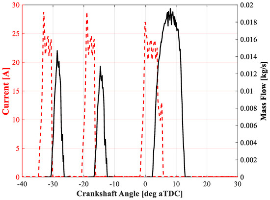
Figure 1.
Electric signals to the injector coils and subsequent fuel mass flow.
As shown in Figure 1, fuel is introduced during the late phase of the compression stroke. The first two injections (pilot and main) are injected earlier with the purpose of increasing pressure and temperature inside the combustion chamber due to their auto-ignition. Before the start of the main injection (which is responsible for delivering torque), the burn rate assumes a premixed shape. The latter pulses strongly affect the subsequent combustion stage. In fact, the relative start of injection (SOI) of each premixed pulse, together with their mutual interaction, influence both the start of combustion (SOC) and the cumulative heat release (CHR) of the premixed stage. Consequently, depending on the way the energy has been released, the subsequent combustion stage provided by the main injection may be profoundly different due to the different pressure and temperature faced by the injected fuel.
Figure 1 shows the electric signals to the injector and the resulting mass flow rates. The delay between the electric signal and the effective injector opening (hydraulic delay), was computed during previous experimental campaigns [18] and is close to 350 μs. At 2000 rpm, it corresponds to 4.2 degrees—a figure that, considering the nature of such combustion, cannot be neglected, since it affects the distribution of the fuel and the interaction with the walls of the combustion chamber.
Pilot and pre-injection were controlled with the same electric pulse with an energizing time (ET) of 350 μs, but the consequent mass flow rates are not symmetrical. In fact, once the pilot injection is released, the closing event generates a pressure wave that travels through the pipes [19]. Depending on the relative position of the two injections, the pre-pulse may be subjected to a different pressure compared to the pilot. Consequently, the overall fuel injected will be different from the nominal value stated by the map. This phenomenon is strictly dependent on the geometric characteristics of the injection system, whose characteristics are highlighted in Table 1.

Table 1.
Injection system characteristics.
Figure 2 reports the latter effect compared to the time interval between the SOI of the subsequent injection and the end of injection (EOI) of the previous one (dwell time, DT).
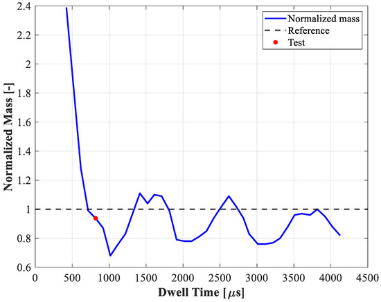
Figure 2.
Behavior of the injected mass with respect to the Dwell Time.
The reference condition represents twice the mass injected during a single pulse, while the red point is the actual value of the normalized mass. Consequently, the coefficient to be applied to the mass flow rate during pre-injection is calculated as follows (Equation (3)):
where represents the interception between the actual DT and the curve of the normalized mass.
Once the injected mass during the early injections has been computed, the duration of the mass flow rate of the main injection during the steady-state phase is adjusted according to the overall fuel injected mass during the cycle (measured by the mass flow rate sensor at the test bench).
2.2. Computational Setup
The calculations were performed using 1/7 of the geometry of the combustion chamber. Since the injector has seven identical holes, the strong symmetry of the combustion chamber allows a reduction in the overall number of computational cells. The STAR-CD 4.28 platform by Siemens was used to build the computational mesh and to set up the models.
Figure 3 reports a section of the computational mesh. The shape of the cells is hexahedral, with a base dimension of 1 mm. The number of cells at bottom dead center (BDC) and TDC are 198,168 and 32,360, respectively.
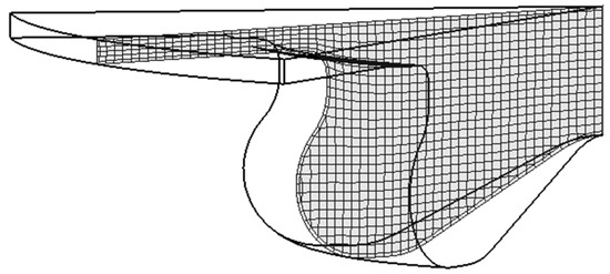
Figure 3.
Computational mesh of the sector of the combustion chamber.
A Reynolds averaged Navier–Stokes (RANS) approach was implemented. To model the turbulence, the RNG model was used. Pressure implicit with splitting operators (PISO) was adopted as the solution algorithm. The maximum residual tolerance for convergence was set to 1 × 10⁻³ for the velocity field, 1 × 10⁻⁴ for the pressure, and 1 × 10⁻¹² the temperature. Regarding the discretization, a second-order central differencing (CD) scheme was implemented for momentum, turbulence, temperature, and density. The base time step size was fixed to almost 8.6 (0.1 deg at 2000 rpm), while during the injection and combustion events, a time step of 2 (0.025 deg at 2000 rpm) was adopted to effectively capture the break-up and burn rate phenomena.
Regarding droplet break-up, the Huh and Gosman model was selected to capture the atomization process [20]. The secondary break-up phenomenon was computed using the model from Reitz and Diwakar [21]. To capture the particle wall interaction, the built-in Bai-ONERA model was selected [22,23]. This model requires knowledge of both the Nukiyama and Leidenfrost temperatures. The first one is computed with a multiplicative coefficient of saturation temperature of 1.25. For the Leidenfrost point, the Habchi model was imposed [24]. The latter droplet-wall interaction model was adopted based on previous studies [25].
To capture the formation of the main pollutants, the models proposed by [26,27] were used to compute NOx and soot, respectively. CO emission was treated as a Flamelet model.
The simulation of the combustion event is described by the progress variable library model-multi fuel (PVM-MF) approach [28]. This model solves the complexity of the simulation of detailed chemistry equations with the adoption of pre-computed tables considering different conditions of pressure, temperature, EGR, and equivalence ratio. Table 2 summarizes all the models implemented during the CFD simulations.

Table 2.
List of models used during the CFD simulations.
The governing equations of the CFD simulation include: (i) classical Navier-Stokes mass and momentum conservation (Equation (4), Equation (5) respectively), (ii) thermal-chemical enthalpy conservation (Equation (6)); (iii) mass transfer equation (Equation (7)); (iv) PVM-MF combustion progress equation (Equation (8)) and reaction rate equations (Equation (9)). In Equations (4)–(9), is the mixture density, is the magnitude of the velocity components, is the stress tensor, is the pressure, is the enthalpy, is the mass fraction of the chemical species, is the combustion progress variable, is the turbulent viscosity, is the turbulent Schmidt number, is the reaction rate of the species (tabulated), subscript is associated to the space direction, is the flux due to diffusion, are source terms (e.g., in the spray contribution is included).
2.3. Boundary and Initial Conditions
A one-dimensional code built in GT-Power v2022 was used to capture the quantities needed by the CFD code during the pre-processing process. The code simulates the operating condition of a turbocharged direct-injection diesel engine whose characteristics are listed in Table 3.

Table 3.
Technical characteristics of the engine.
To reproduce the combustion process, a multi-Wiebe burn rate combustion model was implemented. The Wiebe coefficients were computed with an optimizing procedure in Matlab aimed at reducing the error between the experimental RoHR and the multi-Wiebe model.
The initial conditions for pressure, temperature, and composition in the CFD code were imposed referring to the results provided by the GT-Power model. Instead, the piston temperature was kept fixed at 520 K, while the head and cylinder temperature were kept at 450 K. Table 4 summarizes the boundary and initial conditions adopted during the simulations

Table 4.
Characterization of boundary and initial conditions.
The remaining two boundaries were treated with cyclic conditions. In cyclic boundaries, scalar variables are forced to be equal at corresponding faces on the two regions. Instead, velocity components are equalized using a common local coordinate reference system.
2.4. Grid Sensitivity
In this section, the effect of different mesh structures is presented. The study was conducted modifying the parameters of the sectorial mesh in two main dimensions. The first one represents the number of sub-sectors in the radial direction, while the second one is related to the number of layers in the axial direction.
As shown in Figure 4, the number of cells has a huge impact on the premixed phase of the combustion. In fact, a reduction in the number of cells in either the radial or the axial dimensions generates a higher peak RoHR in the premixed combustion. Consequently, the peak pressure increases accordingly. This behavior is attributed to different atomization and break-up regimes around the injector tip. In fact, a coarser mesh in that region might lead to an unrealistic simulation of spray development. Consequently, the distribution of fuel in the combustion chamber will be different. As shown by the blue traces in Figure 4, a finer mesh is more effective at reproducing the premixed phase. For this reason, the finest mesh was selected for the simulations.
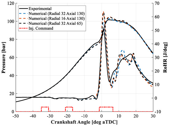
Figure 4.
Comparison between experimental and numerical pressure and RoHR traces with different grid geometries.
The next section deals with the validation of the CFD model through comparison with the quantities provided by the experiments.
3. Results
This section compares the results obtained from the simulation with those measured during the experiments at the test bench. Specifically, the comparison is based on the pressure trace, the corresponding RoHR, and the main pollutants released (NOx and PM emissions).
To assess the validity of the adopted combustion model, validation was performed at a fixed engine speed and engine load (indicated mean effective pressure, IMEP), with a varying center of combustion (angle at 50% of mass burnt, MFB50). The resultant injection patterns are considerably different, enhancing the validity of the PVM-MF model. A fixed engine speed of 2000 rpm and engine load of 14 bar IMEP were selected to replicate the most common engine operating point during the experiments at the test bench. Table 5 lists the operating points of the engine, together with the injection patterns. The actual values of SOI and ET were imposed during the experiments with a feedback controller on MFB50 and IMEP.

Table 5.
Description of the experimental points for the validation procedure.
Figure 5 shows the comparison between the experimental and numerical pressure and RoHR traces at 2000 rpm with four different SOIs for the main injection (points A1 to A4). At the bottom of each figure, the electric injection command is represented synchronized with the crankshaft angle (CA). As the RoHR curves show, the GCI combustion is composed of two stages. For Point A1, for which a more retarded MFB50 is evidenced due to the retarded SOI main injection, the division of the two stages is more prominent. The first two injections (pilot and pre) are responsible for the premixed stage, in which a high amount of energy is released in a small range of CA. Then, the diffusion combustion comes into play due to the main injection.
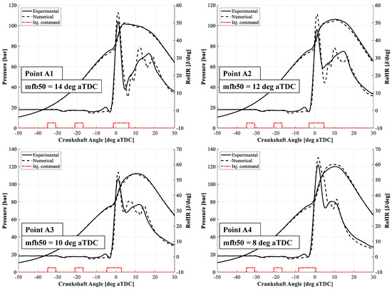
Figure 5.
Comparison between the experimental and numerical pressure and RoHR traces for points A1 to Point A4.
The numerical pressure traces were consistent with the experimental data. The SOC and the overall shape of the premixed stage were comparable with the real one. The angle at which the peak RoHR occurs was almost the same, with a slight overestimation of its value. The simulated diffusion combustion has an oscillating trend that is not visible in the experimental one. On the other hand, the global trend appears to be comparable with the experimental one. The low temperature heat release (LTHR) phase, which occurs before the premixed stage, was not reported in the numerical curve, as the RoHR curve highlights. Consequently, a slight underestimation of the peak motoring pressure was reported in the numerical pressure traces.
Focusing on the RoHR curve before the SOC, behavior during the fuel evaporation phase is effectively reproduced, especially with regard to the pilot pulse. The cooling effect provided by the vaporization of the fuel leads to a reduction in the RoHR curve. This means that hydraulic delay and the droplet atomization and break-up models can reasonably reproduce the behavior during the free spray development.
Comparing NOx emissions, Figure 6 shows both the experimental and numerical trends for Points A1 to A4. Regarding the experimental trends, measurements were performed by means of a Continental SNS14 NOx sensor that counts the parts per million (PPM) at the exhaust tailpipe. Post-processing calculations were then used to evaluate the indicated specific nitrogen oxides (ISNOx) emissions. Concerning the numerical values, the CFD code gives the mass concentration at the end of the simulation. The numerical ISNOx was computed accordingly. The values are in agreement with the experimental ones. As expected, the more anticipated the SOI main injection is, the higher the amount of NOx will be.
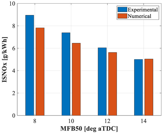
Figure 6.
Comparison between experimental and numerical ISNOx emissions for Points A1 to A4.
This is reasonable since the anticipated main injection leads to higher peak pressure, enhancing the chemical mechanism for NOx formation. The numerical ISNOx emissions slightly underpredict the experimental ones. It is worth noting that the experimental ISNOx results from the combustion of all four cylinders, while the numerical one replicates only the NOx emissions of the fourth cylinder. Since each cylinder has a different SOI main injection due to combustion control, the NOx of each cylinder may differ.
The experimental soot emissions were measured using an AVL Smoke Meter 415S, which provides the filtered smoke number (FSN). Therefore, in order to directly relate the emissions measured during the experiments with the numerical ones, Figure 7 shows the trends of NOx in ppm and soot in FSN compared to the mass concentration calculated by the CFD code. The Pearson coefficient was used to measure the linear dependence between the two quantities. The coefficient is calculated using Equation (10):
where A and B are the two variables, defines the covariance of A and B, and and the standard deviations of A and B.
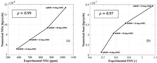
Figure 7.
Comparison between experimental NOx in PPM and corresponding numerical NOx mass per cycle for Points A1 to A4 (a); Comparison between experimental FSN and corresponding numerical Soot concentration for Points A1 to A4 (b).
As the Pearson coefficient states, the correlation between the quantities is almost linear, especially considering the data related to NOx emissions. However, regarding soot emission, the Pearson coefficient is slightly lower than the one for NOx due to values at the extremes. In fact, one or two appear to be underestimated, causing the correlation to deviate from the linearity.
The distribution of NOx inside the combustion chamber is shown in Figure 8 for all the points investigated and for different crank angles. For each mfb50, NOx start generating inside the piston bowl. Then they begin developing towards the squish region from 20 to 30 deg aTDC. At the same time, NOx are generated in the center of the combustion chamber. The location of the maximum concentration is almost the same for all the points, while the absolute value strictly depends on the actual mfb50. In fact, as expected, the more the center of combustion is anticipated, the more the NOx concentration shown in Figure 8 will be higher. This is due to the higher temperature involved during combustion, which favors the generation of NOx.
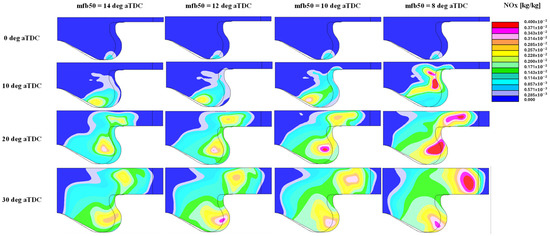
Figure 8.
NOx 3D distribution at different crank angles for each point.
Figure 9 shows the same trends for soot concentration. As highlighted in the second row (10 deg aTDC), soot starts to be generated around the fuel spray. In fact, in this region, very low lambda is expected due to the early mixing phase. The high temperature generated by the combustion process in the leaner regions promotes the formation of soot.
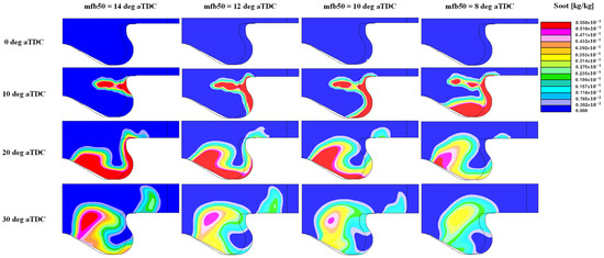
Figure 9.
Soot 3D distribution at different crank angles for each point.
Since the case with the most anticipated SOI (fourth column) generates the highest temperature inside the combustion chamber, at 10 deg aTDC a higher soot concentration is produced. Then, since the subsequent combustion helps to reduce the species, the case at mfb50 = 8 deg aTDC results in a lower soot concentration at 30 deg aTDC compared to the more retarded cases. For this reason, as shown in Figure 7, higher soot concentration is generated in correspondence of mfb50 = 14 deg aTDC.
With regard to the pressure, RoHR traces, and NOx and soot emissions produced by the CFD simulations, it can be concluded that the PVM-MF combustion model obtains consistent results compared to those provided experimentally. Considering the applicability of such methodology, future works will study the role of different SOI in GCI combustion using CFD simulations.
4. Summary and Conclusions
This paper focused on the analysis of the GCI combustion using a combined approach with experimental data and CFD simulations. Such combustion is generated by three closely spaced injections in the late phase of the compression stroke. The first two pulses (pilot and pre-injection) are beneficial to accelerate the auto-ignition of the last one (main injection) as they generate a premixed combustion which increases pressure and temperature inside the combustion chamber. The way the premixed phase burns directly affects engine performance and emissions.
In order to simulate such combustion, several models were taken into account. Starting from the injection profiles, a dedicated code in Matlab was developed to adjust the instantaneous fuel flow rate according to the pressure wave propagation phenomenon and experimental injected mass. Then, a one-dimensional GT-Power model was used to calculate the initial conditions to impose to the CFD code.
Consequently, several CFD simulations were run to match the experimental pressure and RoHR traces with the objective of building a robust model for combustion reproduction.
First, grid sensitivity was investigated by comparing the results of the code with three different grid geometries. The grid with the highest number of cells in both axial and radial directions was chosen, mainly based on the best match with experimental data that did not involve a considerable increase in simulation time.
The results showed good agreement with the experimental data in terms of pressure trace and pollutants released during the combustion event. The validation of the presented model was verified with four different SOI for the main injection. Very high correlation between the experimental and numerical NOx (measured in ppm and concentration, respectively) was achieved, with a Pearson coefficient of 0.99. Similarly, experimental and numerical soot (expressed in FSN and concentration, respectively) obtained a Pearson coefficient of 0.97.
Additionally, 3-D results were presented showing the distribution of both soot and NOx for all the points investigated. The distribution of pollutants agrees with the trends highlighted by the 2-D results.
Future studies will tackle optimization of the GCI concept by working on the injection pattern with a view to reducing the pollutant emissions and increasing performance.
Author Contributions
Conceptualization, D.V., V.M., G.S. and V.R.; methodology, D.V. and V.M.; software, D.V.; validation, D.V.; formal analysis, D.V. and V.R.; investigation, D.V.; resources, D.V., V.R. and G.M.B.; data curation, D.V. and G.S.; writing—original draft preparation, D.V.; writing—review and editing, D.V., G.S. and V.R.; visualization, D.V.; supervision, G.M.B. and V.R.; project administration, V.R.; funding acquisition, V.R. and G.M.B. All authors have read and agreed to the published version of the manuscript.
Funding
This research received no external funding.
Data Availability Statement
The data presented in this study are available on request from the corresponding author due to confidentiality reasons.
Conflicts of Interest
The authors declare that the research was conducted in the absence of any commercial or financial relationships that could be construed as a potential conflict of interest.
Abbreviations
| LTC | low temperature combustion |
| SI | spark ignition |
| CI | compression ignition |
| GCI | gasoline compression ignition |
| TDC | top dead centre |
| RoHR | rate of heat release |
| ICE | internal combustion engine |
| NOx | nitrogen oxides |
| PM | particulate matter |
| EGR | exhaust gas recirculation |
| SOI | start of injection |
| SOC | start of combustion |
| CHR | cumulative heat release |
| ET | energizing time |
| DT | dwell time |
| BDC | bottom dead centre |
| RANS | reynolds averaged navier stokes |
| PISO | pressure implicit |
| CD | central differencing |
| PFM-MF | progress variable model—multi fuel |
| IMEP | indicated mean effective pressure |
| MFB10 | 10% mass fuel burnt |
| MFB50 | 50% mass fuel burnt |
| MFB90 | 90% mass fuel burnt |
| PPM | parts per million |
| LTHR | low temperature heat release |
| CO2 | carbon dioxide |
| deg aTDC | degrees after top dead centre |
| deg bTDC | degrees before top dead centre |
References
- Wang, Z.; Li, L. Effect of Pre-Injection on Combustion and Emission Characteristics of a Diesel Engine Fueled with Diesel/Methanol/n-Butanol Blended Fuel. Processes 2022, 10, 60. [Google Scholar] [CrossRef]
- Wang, Z.; Liu, H.; Reitz, R.D. Knocking combustion in spark-ignition engines. Prog. Energy Combust. Sci. 2017, 61, 78–112. [Google Scholar] [CrossRef]
- Mahendar, S.K.; Erlandsson, A.; Adlercreutz, L.; Mahendar, S.K.; Erlandsson, A.; Adlercreutz, L. Challenges for Spark Ignition Engines in Heavy Duty Application: A Review; SAE International: Warrendale, PA, USA, 2018. [Google Scholar] [CrossRef]
- Krishnamoorthi, M.; Malayalamurthi, R.; He, Z.; Kandasamy, S. A review on low temperature combustion engines: Performance, combustion and emission characteristics. Renew. Sustain. Energy Rev. 2019, 116, 109404. [Google Scholar] [CrossRef]
- Sellnau, M.; Sinnamon, J.; Hoyer, K.; Husted, H. Gasoline Direct Injection Compression Ignition (GDCI)—Diesel-like Efficiency with Low CO2 Emissions. SAE Int. J. Engines 2011, 4, 2010–2022. [Google Scholar] [CrossRef]
- Sellnau, M.; Foster, M.; Moore, W.; Sinnamon, J.; Hoyer, K.; Klemm, W. Pathway to 50% Brake Thermal Efficiency Using Gasoline Direct Injection Compression Ignition. SAE Int. J. Adv. Curr. Pract. Mob. 2019, 1, 1581–1603. [Google Scholar] [CrossRef]
- Cracknell, R.F.; Ariztegui, J.; Dubois, T.; Hamje, H.; Pellegrini, L.; Rickeard, D.; Rose, K.D.; Deppenkemper, K.; Graziano, B.; Heufer, K.A.; et al. Modelling a Gasoline Compression Ignition (GCI) Engine Concept; SAE International: Warrendale, PA, USA, 2014. [Google Scholar] [CrossRef]
- Loeper, P.; Ra, Y.; Adams, C.; Foster, D.E.; Ghandhi, J.; Andrie, M.; Krieger, R.; Durrett, R.; Loeper, P.; Ra, Y.; et al. Experimental Investigation of Light-Medium Load Operating Sensitivity in a Gasoline Compression Ignition (GCI) Light-Duty Diesel Engine; SAE International: Warrendale, PA, USA, 2013. [Google Scholar] [CrossRef]
- Stola, F.; Ravaglioli, V.; Silvagni, G.; Ponti, F.; De Cesare, M. Injection Pattern Investigation for Gasoline Partially Premixed Combustion Analysis; SAE International: Warrendale, PA, USA, 2019. [Google Scholar] [CrossRef]
- Heywood, J.B. Internal Combustion Engine Fundamentals, 2nd ed.; McGraw-Hill Education: New York, NY, USA, 2018; Available online: https://www.accessengineeringlibrary.com/content/book/9781260116106 (accessed on 4 June 2024).
- Wu, H.; Mi, S.; Qian, Y.; Zhang, Y.; Zhao, W.; Lu, X. Investigation of injection parameters coupled with fuel reactivity on combustion and emissions in dual direct-injection GCI engine. Int. J. Engine Res. 2024, 25, 14680874241229489. [Google Scholar] [CrossRef]
- Agarwal, A.K.; Solanki, V.S.; Krishnamoorthi, M. Gasoline compression ignition (GCI) combustion in a light-duty engine using double injection strategy. Appl. Therm. Eng. 2023, 223, 120006. [Google Scholar] [CrossRef]
- Agarwal, A.K.; Solanki, V.S.; Krishnamoorthi, M. Experimental Evaluation of Pilot and Main Injection Strategies on Gasoline Compression Ignition Engine—Part 1: Combustion Characteristics. SAE Int. J. Engines 2023, 16, 809–832. [Google Scholar] [CrossRef]
- Badra, J.; Alhussaini, A.; Sim, J.; Viollet, Y.; Amer, A. Parametric Study to Optimize Gasoline Compression Ignition Operation under Low Load Condition Using CFD; SAE International: Warrendale, PA, USA, 2021. [Google Scholar] [CrossRef]
- Paz, J.; Staaden, D.; Kokjohn, S. Gasoline Compression Ignition Operation of a Heavy-Duty Engine at High Load; SAE International: Warrendale, PA, USA, 2018. [Google Scholar] [CrossRef]
- Pamminger, M.; Addepalli, S.K.; Scarcelli, R.; Wallner, T. The Impact of Fuel Injection Strategies and Compression Ratio on Combustion and Performance of a Heavy-Duty Gasoline Compression Ignition Engine; SAE International: Warrendale, PA, USA, 2022. [Google Scholar] [CrossRef]
- Ravaglioli, V.; Ponti, F.; Silvagni, G.; Moro, D.; Stola, F.; De Cesare, M. Performance Assessment of Gasoline PPC in a Light-Duty CI Engine; SAE International: Warrendale, PA, USA, 2022. [Google Scholar] [CrossRef]
- Viscione, D.; Mariani, V.; Falfari, S.; Bianchi, G.M.; Ravaglioli, V.; Silvagni, G.; Montanaro, A.; Allocca, L. Unconventional gasoline spray injection events: Compared evolution of experimental data and numerical simulations. Fuel 2024, 355, 129438. [Google Scholar] [CrossRef]
- Silvagni, G.; Ravaglioli, V.; Ponti, F.; Corti, E.; Raggini, L.; Scocozza, G.; Stola, F.; De Cesare, M. Development of a Predictive Pressure Waves Model for High-Pressure Common Rail Injection Systems. SAE Int. J. Engines 2021, 15, 719–741. [Google Scholar] [CrossRef]
- Huh, K.Y.; Gosman, A.D. A phenomenological model of diesel spray atomization. In Proceedings of the International Conference on Multiphase Flows, Tsukuba, Japan, 24–27 September 1991. [Google Scholar]
- Reitz, R.D.; Diwakar, R. Effect of Drop Breakup on Fuel Sprays. SAE Trans. 1986, 95, 860469. [Google Scholar] [CrossRef]
- Bai, C.; Gosman, A.D. Development of Methodology for Spray Impingement Simulation. SAE Trans. 1995, 104, 950283. [Google Scholar] [CrossRef]
- Rosa, G.; Villedieu, P.; Dewitte, J.; Lavergne, G. A new droplet-wall interaction model. In Proceedings of the 2nd Colloque INCA, Rouen, France, 23–24 October 2008.
- Habchi, C. A Comprehensive Model for Liquid Film Boiling in Internal Combustion Engines. Oil Gas Sci. Technol.–Revue l’Institut Français Pétrole 2010, 65, 331–343. [Google Scholar] [CrossRef][Green Version]
- Viscione, D.; Silvagni, G.; Falfari, S.; Bianchi, G.M.; Ravaglioli, V.; Mariani, V.; Allocca, L.; Montanaro, A.; Meccariello, G. Experimental-Numerical Analysis of Gasoline Spray-Wall Impingement at Ultra-High Injection Pressure for GCI Application. In Proceedings of the 16th International Conference on Engines & Vehicles, Capri, Italy, 10–14 September 2023. [Google Scholar] [CrossRef]
- Karlsson, A.; Magnusson, I.; Balthasar, M.; Mauss, F.; Karlsson, A.; Magnusson, I.; Balthasar, M.; Mauss, F. Simulation of Soot Formation under Diesel Engine Conditions Using a Detailed Kinetic Soot Model; SAE International: Warrendale, PA, USA, 1998. [Google Scholar] [CrossRef]
- Das, S.; Houtz, P.J.; Reitz, R.D. Effect of injection spray angle and combustion chamber geometry on engine performance and emission characteristics of a large bore diesel engine. Am. Soc. Mech. Eng. Int. Combust. Engine Div. Publ. ICE 1999, 32, 1–12. [Google Scholar]
- Bo, T.; Rawat, R.; Johns, R.; Mauss, F. OS3-6 Multi-Fuel and Mixed-Mode IC Engine Combustion Simulation with a Detailed Chemistry based Progress Variable Library Approach(OS3 Application of chemical kinetics to combustion modeling, Organized Session Papers). In Proceedings of the International Symposium on Diagnostics and Modeling of Combustion in Internal Combustion Engines, Fukuoka, Japan, 23–26 July 2012; pp. 146–151. [Google Scholar] [CrossRef]
Disclaimer/Publisher’s Note: The statements, opinions and data contained in all publications are solely those of the individual author(s) and contributor(s) and not of MDPI and/or the editor(s). MDPI and/or the editor(s) disclaim responsibility for any injury to people or property resulting from any ideas, methods, instructions or products referred to in the content. |
© 2024 by the authors. Licensee MDPI, Basel, Switzerland. This article is an open access article distributed under the terms and conditions of the Creative Commons Attribution (CC BY) license (https://creativecommons.org/licenses/by/4.0/).